EP2539632B1 - Kühlkörper für eine lichtquelle - Google Patents
Kühlkörper für eine lichtquelle Download PDFInfo
- Publication number
- EP2539632B1 EP2539632B1 EP11704788.6A EP11704788A EP2539632B1 EP 2539632 B1 EP2539632 B1 EP 2539632B1 EP 11704788 A EP11704788 A EP 11704788A EP 2539632 B1 EP2539632 B1 EP 2539632B1
- Authority
- EP
- European Patent Office
- Prior art keywords
- light source
- heat sink
- outer body
- central
- central body
- Prior art date
- Legal status (The legal status is an assumption and is not a legal conclusion. Google has not performed a legal analysis and makes no representation as to the accuracy of the status listed.)
- Active
Links
Images

Classifications
-
- F—MECHANICAL ENGINEERING; LIGHTING; HEATING; WEAPONS; BLASTING
- F21—LIGHTING
- F21V—FUNCTIONAL FEATURES OR DETAILS OF LIGHTING DEVICES OR SYSTEMS THEREOF; STRUCTURAL COMBINATIONS OF LIGHTING DEVICES WITH OTHER ARTICLES, NOT OTHERWISE PROVIDED FOR
- F21V29/00—Protecting lighting devices from thermal damage; Cooling or heating arrangements specially adapted for lighting devices or systems
- F21V29/50—Cooling arrangements
- F21V29/70—Cooling arrangements characterised by passive heat-dissipating elements, e.g. heat-sinks
- F21V29/74—Cooling arrangements characterised by passive heat-dissipating elements, e.g. heat-sinks with fins or blades
- F21V29/77—Cooling arrangements characterised by passive heat-dissipating elements, e.g. heat-sinks with fins or blades with essentially identical diverging planar fins or blades, e.g. with fan-like or star-like cross-section
- F21V29/773—Cooling arrangements characterised by passive heat-dissipating elements, e.g. heat-sinks with fins or blades with essentially identical diverging planar fins or blades, e.g. with fan-like or star-like cross-section the planes containing the fins or blades having the direction of the light emitting axis
-
- F—MECHANICAL ENGINEERING; LIGHTING; HEATING; WEAPONS; BLASTING
- F21—LIGHTING
- F21S—NON-PORTABLE LIGHTING DEVICES; SYSTEMS THEREOF; VEHICLE LIGHTING DEVICES SPECIALLY ADAPTED FOR VEHICLE EXTERIORS
- F21S8/00—Lighting devices intended for fixed installation
- F21S8/02—Lighting devices intended for fixed installation of recess-mounted type, e.g. downlighters
- F21S8/026—Lighting devices intended for fixed installation of recess-mounted type, e.g. downlighters intended to be recessed in a ceiling or like overhead structure, e.g. suspended ceiling
-
- F—MECHANICAL ENGINEERING; LIGHTING; HEATING; WEAPONS; BLASTING
- F21—LIGHTING
- F21Y—INDEXING SCHEME ASSOCIATED WITH SUBCLASSES F21K, F21L, F21S and F21V, RELATING TO THE FORM OR THE KIND OF THE LIGHT SOURCES OR OF THE COLOUR OF THE LIGHT EMITTED
- F21Y2105/00—Planar light sources
- F21Y2105/10—Planar light sources comprising a two-dimensional [2D] array of point-like light-generating elements
-
- F—MECHANICAL ENGINEERING; LIGHTING; HEATING; WEAPONS; BLASTING
- F21—LIGHTING
- F21Y—INDEXING SCHEME ASSOCIATED WITH SUBCLASSES F21K, F21L, F21S and F21V, RELATING TO THE FORM OR THE KIND OF THE LIGHT SOURCES OR OF THE COLOUR OF THE LIGHT EMITTED
- F21Y2115/00—Light-generating elements of semiconductor light sources
- F21Y2115/10—Light-emitting diodes [LED]
-
- Y—GENERAL TAGGING OF NEW TECHNOLOGICAL DEVELOPMENTS; GENERAL TAGGING OF CROSS-SECTIONAL TECHNOLOGIES SPANNING OVER SEVERAL SECTIONS OF THE IPC; TECHNICAL SUBJECTS COVERED BY FORMER USPC CROSS-REFERENCE ART COLLECTIONS [XRACs] AND DIGESTS
- Y10—TECHNICAL SUBJECTS COVERED BY FORMER USPC
- Y10T—TECHNICAL SUBJECTS COVERED BY FORMER US CLASSIFICATION
- Y10T29/00—Metal working
- Y10T29/49—Method of mechanical manufacture
- Y10T29/49826—Assembling or joining
Definitions
- the present invention relates to a heat sink, which is provided for cooling a light source.
- the invention relates to a heat sink for an LED light source, wherein the heat sink with the light source may for example be part of a so-called downlight.
- LED-based light sources have been finding increasing use in lighting applications lately.
- the luminous intensities achievable with LEDs are so high in the meantime that in almost all cases previously used light sources - for example light bulbs or fluorescent lamps - can be replaced by LEDs.
- LEDs With regard to their reliability and the possibilities for controlling, LEDs have clear advantages.
- a conventional heat sink is usually made of metal - especially aluminum - and is designed so that it forms a large contact area with the environment.
- the heat sink is generally formed lamellar or provided with corresponding fins or cooling fins.
- hitherto heat sinks were designed primarily as a cast aluminum body.
- the cost of producing such Aluminium horrguss republic is relatively high and therefore associated with high costs.
- heatsinks also have a not inconsiderable weight.
- an LED module with a heat sink assembly is known in which a thermally conductive core is press-fitted to an annular fin assembly.
- an automotive LED headlight in which a cylindrical module on which the light source is arranged is connected to an annular cooling rib arrangement.
- an LED light emitting device with a heat sink which has a bottom plate, which engages with a cylindrical projection in an annular cooling fin arrangement.
- a heat sink for LEDs is known, in which a columnar middle part is arranged in an annular cooling rib arrangement.
- an LED headlamp module that includes a heat sink, a main body, and an LED unit.
- the main body has a receiving space for the LED unit, and the heat sink encloses the main body, so that the heat of the LED unit can be quickly absorbed by the main body of the heat sink.
- the present invention has for its object to provide a novel heat sink for cooling light sources, which has good cooling properties and at the same time can be relatively easily and inexpensively manufactured.
- the above-mentioned aluminum die castings which have heretofore been used as heatsinks have generally been one-piece elements.
- the invention proposes to form the heat sink in several parts, in particular in two parts. He has for this purpose an annular outer body and a central body, which is formed by a separate element and arranged in a central opening of the outer body.
- a heat sink is accordingly proposed for a light source, in particular for an LED light source, wherein the heat sink has an annular outer body and a central body which is formed by a separate element and arranged in a central opening of the outer body.
- a method is also proposed for producing a heat sink for a light source, in particular for an LED light source, wherein initially a ring-like outer body is provided with a central opening and then into the opening a central body is used.
- the central body forms a flat support surface for the light source.
- the central body has means for fastening the light source. These may be formed for example by drilling or the like.
- the outer body has a recess for the arrangement of the light source.
- the central body is an integrally formed solid material body; In this case, the central body has a plate on one side of a cylinder-like projection is arranged, wherein the cylinder-like projection is inserted into the opening of the outer body and wherein the plate forms a flat bottom surface of the recess and having holes for fixing the light source.
- outer body and central body are preferably carried out in that the outer body is shrunk onto the central body. hereby a full-surface contact is ensured, which allows a good transfer of heat from the central body to the outer body.
- the subdivision of the heat sink according to the invention in particular opens up the possibility of producing the outer body in the extrusion process. This procedure is much simpler and cheaper than the die-casting process, which is why the manufacturing costs for the heat sink significantly can be reduced. Also, a weight reduction of the heat sink is achieved with consistently good cooling properties.
- the central body itself is preferably designed as a solid material body in order to optimize the removal of the heat emanating from the light source.
- the heat sink according to the invention is used in the embodiment described below in a so-called downlight, so a recessed luminaire, which is complained in the circular opening of a ceiling used. In such an application, the properties of the heat sink in a particularly advantageous manner to bear.
- the heat sink according to the invention could also be used in other types of luminaires.
- the heat sink 10 is the central element of the lamp. In particular, the heat sink 10 also serves to hold other elements of the lamp. 1
- the heat sink 10 has the shape of a flat cylinder and is provided over its peripheral region with numerous fins or cooling fins 11, through which the surface is increased. Heat exchange with the environment is optimized by this increase in surface area.
- the heat sink 10 also serves to support a light source, which in the present case is, in particular, an LED light source.
- a light source which in the present case is, in particular, an LED light source.
- several LEDs can be arranged in a matrix-like manner on a circuit board. Since the LEDs themselves represent almost punctiform light sources, an optical element 2, for example a diffusing screen, is arranged in front of the LEDs to even out the light output. As a result, the individual caused by the LEDs so-called hotspots are resolved and it results in the appearance of a bright and evenly luminous surface.
- the light output to the bottom then takes place via a pot-shaped reflector 3, which is coupled with its upper side to the heat sink 10 and defines with its underside a circular light exit opening.
- the heat sink 10 is formed in two parts and consists on the one hand of an annular outer body 15, the in FIG. 3 is shown, and a central body 20 which in the FIGS. 4a to 4c is shown.
- the annular outer body 15 consists essentially of a circular array of fins 11 extending laterally from a central opening 16 circumferentially.
- the fins 11 can - as in FIG. 3 shown - on the way to the outside again branch Y-shaped, whereby an additional increase in the surface is achieved.
- the slats 11 close the aforementioned opening 16, which is circular.
- the in FIG. 3 illustrated outer body 15 can be produced in a simple manner in an extrusion process. This process is much easier and cheaper to carry out than a production in aluminum die-casting. In the extrusion molding process, a final metal body having the cross-sectional configuration shown in the figures is made larger in length. This rod-like structure then only has to be cut to the appropriate length of the heat sink. Furthermore, then by means of contrasting Method, such as milling or the like of the outer body provided with a recess 17 which serves the arrangement of the light source and a reflector, not shown.
- the second element which ultimately forms the heat sink 10, is in the FIGS. 4a to 4c illustrated central body 20, which is preferably a solid material body, which is in particular integrally formed. He first has a larger disc 21, on one side of a cylinder-like projection 22 is arranged. The outer contour of the projection 22 corresponds to the opening 16 of the outer body 15, so that the central body 20 can be accurately inserted into the outer body 15 as described below.
- the attachment of the central body 20 to the outer body 15 is preferably carried out by shrinking.
- the outer body 15 is first heated so that it expands slightly and in particular the cross-sectional area of the passage opening 16 is increased. In this state, the cylindrical projection 22 of the central body 20 can be inserted into the opening 16.
- the outer body 15 is cooled and shrinks in this case on the projection 22 of the central body 20.
- This approach allows you to connect both elements without the use of additional tools. At the same time a full-surface contact of both elements is ensured, whereby an optimal heat transfer is ensured.
- FIG. 6 After inserting the central body 20 in the outer body 15 then results in the Figures 5 and 6 illustrated arrangement, in particular FIG. 6 can be removed that the plate 21 of the central body 20 now forms a flat bottom surface of the recess 17.
- a light source 30 such as FIG. 7 shows.
- the light source 30 is formed in the illustrated embodiment by a plurality of LEDs 32, which are arranged together on a circuit board 31. Through the plate 21 of the central body 20 a full-surface contact with the board 31 is ensured, so that an optimal thermal coupling is achieved.
- the heat transfer can be further optimized by the fact that between the board 31 and support plate 21, a thermally conductive material, For example, a corresponding paste or the like is provided.
- a thermally conductive material For example, a corresponding paste or the like is provided.
- an effective thermal coupling between the light sources and the heat sink 10 is present.
- a strain relief device 35 are attached, via which leading to the LED board 31 cables can be fixed.
- the present invention provides a heat sink which on the one hand can be produced simply and inexpensively, on the other hand ensures optimum heat transfer or removal of the heat generated by a light source.
Landscapes
- Engineering & Computer Science (AREA)
- General Engineering & Computer Science (AREA)
- Arrangement Of Elements, Cooling, Sealing, Or The Like Of Lighting Devices (AREA)
- Led Device Packages (AREA)
- Non-Portable Lighting Devices Or Systems Thereof (AREA)
Description
- Die vorliegende Erfindung betrifft einen Kühlkörper, der zur Kühlung einer Lichtquelle vorgesehen ist. Insbesondere betrifft die Erfindung einen Kühlkörper für eine LED-Lichtquelle, wobei der Kühlkörper mit der Lichtquelle beispielsweise Bestandteil eines sogenannten Downlights sein kann.
- Lichtquellen auf LED-Basis finden in letzter Zeit zunehmend auch in Beleuchtungsanwendungen Verwendung. Die mit LEDs erreichbaren Leuchtstärken sind zwischenzeitlich so hoch, dass in nahezu allen Fällen bislang verwendete Lichtquellen - beispielsweise Glühbirnen oder Leuchtstofflampen - durch LEDs ersetzt werden können. Hinsichtlich ihrer Betriebssicherheit sowie der Möglichkeiten zur Ansteuerung weisen dabei LEDs deutliche Vorteile auf.
- Auf der anderen Seite bringt die Nutzung von LEDs zu Beleuchtungszwecken das Problem mit sich, dass effektive Maßnahmen zum Kühlen der Lichtquellen eingesetzt werden müssen. Die beim Betrieb von LEDs auftretende Verlustwärme ist verhältnismäßig hoch und ferner auch auf einen kleinen Bereich konzentriert, so dass zur Vermeidung von Beschädigungen Maßnahmen getroffen werden müssen, um die Wärme schnell und effektiv abzuführen. Üblicherweise werden hierzu Kühlkörper eingesetzt, welche thermisch in Verbindung mit den LEDs stehen.
- Ein klassischer Kühlkörper besteht üblicherweise aus Metall - insbesondere Aluminium - und ist derart ausgebildet, dass er eine große Kontaktfläche mit der Umgebung bildet. Hierzu ist der Kühlkörper in der Regel lamellenartig ausgebildet bzw. mit entsprechenden Lamellen oder Kühlrippen versehen. Eine derartige Struktur ist allerdings verhältnismäßig komplex, weshalb bislang Kühlkörper in erster Linie als Aluminiumdruckgusskörper ausgeführt waren. Der Aufwand zur Herstellung derartiger Aluminiumdruckgusskörper ist verhältnismäßig hoch und dementsprechend mit hohen Kosten verbunden. Ferner weisen derartige Kühlkörper auch ein nicht zu vernachlässigendes Gewicht auf.
- Aus der
WO 02/097884 A1 - Aus der
US 6,974,233 B1 ist eine Leuchte bekannt, bei der ein Glasreflektor über einen Trägeransatz mit einer ringförmigen Kühlrippenanordnung verbunden ist. - Aus der
US 2006/0002125 A1 ist ein LED-Kraftfahrzeugscheinwerfer bekannt, bei dem ein zylinderförmiges Modul, an dem die Lichtquelle angeordnet ist, mit einer ringförmigen Kühlrippenanordnung verbunden ist. - Aus der
US 2008/0192436 A1 ist eine LED-Lichtabgabeanordnung mit einem Kühlkörper bekannt, der eine Bodenplatte aufweist, die mit einem zylindrischen Ansatz in eine ringförmige Kühlrippenanordnung eingreift. - Aus der
EP 2 133 914 A2 ist ein Kühlkörper für LEDs bekannt, bei dem ein säulenartiges Mittelteil in einer ringförmigen Kühlrippenanordnung angeordnet ist. - Aus der
DE 20 2006 009 553 U1 ist ein LED-Scheinwerfermodul bekannt, das einen Kühlkörper, einen Hauptkörper und eine LED-Einheit umfasst. Der Hauptkörper weist einen Aufnahmeraum für die LED-Einheit auf und der Kühlkörper umschließt den Hauptkörper, so dass die Wärme der LED-Einheit schnell durch den Hauptkörper von dem Kühlkörper absorbiert werden kann. - Der vorliegenden Erfindung liegt die Aufgabe zugrunde, einen neuartigen Kühlkörper zum Kühlen von Lichtquellen bereitzustellen, der gute Kühleigenschaften aufweist und gleichzeitig verhältnismäßig einfach und kostengünstig hergestellt werden kann.
- Die Aufgabe wird durch einen Kühlkörper mit den Merkmalen des Anspruchs 1 sowie durch ein Verfahren zum Herstellen eines Kühlkörpers gemäß Anspruch 5 gelöst. Vorteilhafte Weiterbildungen der Erfindung sind Gegenstand der abhängigen Ansprüche.
- Bei den oben erwähnten Aluminiumdruckgusskörpern, welche bislang als Kühlkörper verwendet wurden, handelte es sich in der Regel um einstückige Elemente. Demgegenüber wird erfindungsgemäß vorgeschlagen, den Kühlkörper mehrteilig, insbesondere zweiteilig auszubilden. Er weist hierfür einen ringartigen Außenkörper sowie einen Zentralkörper auf, der durch ein separates Element gebildet und in einer zentralen Öffnung des Außenkörpers angeordnet ist.
- Gemäß der vorliegenden Erfindung wird dementsprechend ein Kühlkörper für eine Lichtquelle, insbesondere für eine LED-Lichtquelle vorgeschlagen, wobei der Kühlkörper einen ringartigen Außenkörper sowie einen Zentralkörper aufweist, der durch ein separates Element gebildet und in einer zentralen Öffnung des Außenkörpers angeordnet ist. Gemäß der vorliegenden Erfindung wird auch ein Verfahren zum Erstellen eines Kühlkörpers für eine Lichtquelle, insbesondere für eine LED-Lichtquelle vorgeschlagen, wobei zunächst ein ringartiger Außenkörper mit einer zentralen Öffnung bereitgestellt wird und anschließend in die Öffnung ein Zentralkörper eingesetzt wird.
- Vorzugsweise bildet der Zentralkörper eine ebene Auflagefläche für die Lichtquelle. Erfindungsgemäß weist der Zentralkörper Mittel zur Befestigung der Lichtquelle auf. Diese können beispielsweise durch Bohrungen oder dergleichen gebildet sein. Der Außenkörper weist eine Vertiefung zur Anordnung der Lichtquelle auf. Bei dem Zentralkörper handelt es sich um einen einstückig ausgebildeten Vollmaterialkörper; dabei weist der Zentralkörper eine Platte auf, an deren einer Seite ein zylinderartiger Vorsprung angeordnet ist, wobei der zylinderartige Vorsprung in die Öffnung des Außenkörpers eingesetzt ist und wobei die Platte eine ebene Bodenfläche der Vertiefung bildet und Bohrungen zur Befestigung der Lichtquelle aufweist.
- Das Zusammenfügen von Außenkörper und Zentralkörper erfolgt vorzugsweise dadurch, dass der Außenkörper auf den Zentralkörper aufgeschrumpft wird. Hierdurch ist ein vollflächiger Kontakt gewährleistet, der eine gute Übertragung der Wärme von dem Zentralkörper auf den Außenkörper ermöglicht.
- Die erfmdungsgemäße Unterteilung des Kühlkörpers eröffnet insbesondere die Möglichkeit, den Außenkörper im Strangpressverfahren herzustellen. Diese Vorgehensweise ist deutlich einfacher und kostengünstiger als das Druckgussverfahren, weshalb die Herstellungskosten für den Kühlkörper deutlich reduziert werden können. Auch eine Gewichtsreduzierung des Kühlkörpers wird bei gleichbleibend guten Kühleigenschaften erzielt. Der Zentralkörper selbst ist vorzugsweise als Vollmaterialkörper ausgebildet, um die Abführung der von der Lichtquelle ausgehenden Wärme zu optimieren.
- Nachfolgend soll die Erfindung anhand der beiliegenden Zeichnung näher erläutert werden. Es zeigen:
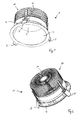
- Fig. 1 und 2
- Ansichten einer Einbauleuchte in Form eines sogenannten Downlights, bei welcher der erfindungsgemäße Kühlkörper zum Einsatz kommt;
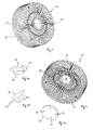
- Fig. 3
- eine Ansicht des Außenkörpers des erfindungsgemäßen Kühlkörpers;
- Fig. 4a bis 4c
- Ansichten eines Zentralkörpers des erfindungsgemäßen Kühlkörpers;
- Fig. 5 und 6
- Ansichten des durch Außenkörper und Zentralkörper gebildeten Kühlkörpers und
- Fig. 7
- eine Ansicht eines erfindungsgemäßen Kühlkörpers mit daran befestigter LED-Lichtquelle.
- Der erfindungsgemäße Kühlkörper wird bei dem nachfolgend beschriebenen Ausführungsbeispiel bei einem sogenannten Downlight, also einer Einbauleuchte, die in der kreisförmigen Öffnung einer Decke moniert wird, verwendet. Bei einem derartigen Anwendungsfall kommen die Eigenschaften des Kühlkörpers in besonders vorteilhafter Weise zum Tragen. Gleichwohl ist darauf hinzuweisen, dass der erfindungsgemäße Kühlkörper auch bei anderen Leuchtentypen eingesetzt werden könnte.
- Bei dem in den
Figuren 1 und 2 dargestellten Downlight 1 stellt der Kühlkörper 10 das zentrale Element der Leuchte dar. Insbesondere dient der Kühlkörper 10 gleichzeitig auch der Halterung weiterer Elemente der Leuchte 1. - Der Kühlkörper 10 weist die Form eines flachen Zylinders auf und ist über seinen Umfangsbereich hinweg mit zahlreichen Lamellen bzw. Kühlrippen 11 versehen, durch welche die Oberfläche vergrößert wird. Ein Wärmeaustausch mit der Umgebung wird durch diese Oberflächenvergrößerung optimiert.
- Der Kühlkörper 10 dient ferner der Lagerung einer Lichtquelle, bei der es sich im vorliegenden Fall insbesondere um eine LED-Lichtquelle handelt. Insbesondere können hierfür - wie nachfolgend näher beschrieben - mehrere LEDs matrixartig auf einer Platine angeordnet sein. Da die LEDs selbst nahezu punktförmige Lichtquellen darstellen, ist zur Vergleichmäßigung der Lichtabgabe vor den LEDs ein optisches Element 2, beispielsweise eine Streuscheibe angeordnet. Hierdurch werden die einzelnen durch die LEDs hervorgerufenen sog. Hotspots aufgelöst und es ergibt sich das Erscheinungsbild einer hell und gleichmäßig leuchtenden Fläche. Die Lichtabgabe zur Unterseite erfolgt dann über einen topfförmigen Reflektor 3, der mit seiner Oberseite mit dem Kühlkörper 10 gekoppelt ist und mit seiner Unterseite eine kreisförmige Lichtaustrittsöffnung definiert. Die Befestigung der Baueinheit bestehend aus Kühlkörper 10 und Reflektor 3 in einer Decke erfolgt mit Hilfe eines Montagerings 4, der zunächst in die Deckenöffnung eingesetzt und dort mittels dreier ausschwenkbarer Rastarme 5 fixiert wird. Anschließend wird die Leuchte 1 von der Unterseite her in diesen Montagering 4 eingesetzt und beispielsweise durch Verdrehen fixiert. Derartige Montagesysteme für Downlights sind bereits hinlänglich bekannt und sollen dementsprechend nachfolgend nicht näher erläutert werden.
- Die Besonderheit des Kühlkörpers 10 besteht in dessen Ausgestaltung und soll nachfolgend beschrieben werden. Erfindungsgemäß ist der Kühlkörper 10 zweiteilig ausgebildet und besteht zum einen aus einem ringförmigen Außenkörper 15, der in
Figur 3 gezeigt ist, sowie einem Zentralkörper 20, der in denFiguren 4a bis 4c gezeigt ist. - Der ringförmige Außenkörper 15 besteht im Wesentlichen aus einer kreisförmigen Anordnung von Lamellen bzw. Rippen 11, die sich von einer zentralen Öffnung 16 über den Umfang hinweg seitlich erstrecken. Die Lamellen 11 können sich - wie in
Figur 3 gezeigt - auf dem Weg zur Außenseite hin nochmals Y-förmig verzweigen, wodurch eine zusätzliche Vergrößerung der Oberfläche erzielt wird. An ihrem Innenumfang schließen die Lamellen 11 die bereits erwähnte Öffnung 16 ein, welche kreisförmig ausgebildet ist. - Der in
Figur 3 dargestellte Außenkörper 15 lässt sich in einfacher Weise im Rahmen eines Strangpressverfahrens herstellen. Dieses Verfahren ist deutlich einfacher und kostengünstiger durchzuführen als eine Herstellung im Aluminiumdruckgussverfahren. Beim Strangpressverfahren wird letztendliche ein Metallkörper, der die in den Figuren gezeigte Querschnittskonfiguration aufweist, mit einer größeren Länge erstellt. Dieses stangenartige Gebilde muss dann nur noch lediglich auf die entsprechende Länge des Kühlkörpers abgeschnitten werden. Desweiteren wird dann mittels abhebender Verfahren, beispielsweise Fräsen oder dergleichen der Außenkörper mit einer Vertiefung 17 versehen, welche der Anordnung der Lichtquelle sowie eines nicht näher dargestellten Reflektors dient. - Das zweite Element welches letztendlich den Kühlkörper 10 bildet, ist der in den
Figuren 4a bis 4c dargestellte Zentralkörper 20, bei dem es sich vorzugsweise um einen Vollmaterialkörper handelt, der insbesondere einstückig ausgebildet ist. Er weist zunächst eine größere Scheibe 21 auf, an deren einer Seite ein zylinderartiger Vorsprung 22 angeordnet ist. Die Außenkontur des Vorsprungs 22 entspricht dabei der Öffnung 16 des Außenkörpers 15, so dass der Zentralkörper 20 wie nachfolgend beschrieben passgenau in den Außenkörper 15 eingesetzt werden kann. Die Befestigung des Zentralkörpers 20 an dem Außenkörper 15 erfolgt dabei vorzugsweise durch Aufschrumpfen. Hierzu wird zunächst der Außenkörper 15 erwärmt, so dass er sich leicht ausdehnt und insbesondere die Querschnittsfläche der Durchgangsöffnung 16 vergrößert ist. In diesem Zustand kann der zylinderförmige Vorsprung 22 des Zentralkörpers 20 in die Öffnung 16 eingesetzt werden. Anschließend wird der Außenkörper 15 abgekühlt und schrumpft hierbei auf den Vorsprung 22 des Zentralkörpers 20 auf. Diese Vorgehensweise erlaubt es, beide Elemente ohne die Nutzung zusätzlicher Hilfsmittel miteinander zu verbinden. Gleichzeitig ist ein vollflächiger Kontakt beider Elementen sichergestellt, wodurch eine optimale Wärmeübertragung gewährleistet ist. - Anstelle der dargestellten Kreisform für die Durchgangsöffnung 16 sowie den Vorsprung 22 könnten selbstverständlich auch andere Querschnittsformen gewählt werden. Die dargestellte Konfiguration bringt allerdings im Hinblick auf die Herstellung der Elemente Vorteile mit sich.
- Nach Einsetzen des Zentralkörpers 20 in den Außenkörper 15 ergibt sich dann die in den
Figuren 5 und6 dargestellte Anordnung, wobei insbesondereFigur 6 entnehmbar ist, dass die Platte 21 des Zentralkörpers 20 nunmehr eine ebene Bodenfläche der Ausnehmung 17 bildet. Diese kann zum Anordnen einer Lichtquelle 30 genutzt werden, wieFigur 7 zeigt. Die Lichtquelle 30 wird im dargestellten Ausführungsbeispiel durch eine Mehrzahl von LEDs 32 gebildet, die gemeinsam auf einer Platine 31 angeordnet sind. Durch die Platte 21 des Zentralkörpers 20 ist ein vollflächiger Kontakt mit der Platine 31 gewährleistet, so dass eine optimale Wärmekopplung erzielt wird. Die Befestigung der Platine 31 an dem Zentralkörper 20 erfolgt mit Hilfe von vier Schrauben 32, welche in entsprechende Bohrungen 23 an der Platte 22 eingreifen Dabei kann die Wärmeübertragung zusätzlich dadurch optimiert werden, dass zwischen Platine 31 und Auflageplatte 21 ein wärmeleitfähiges Material, beispielsweise eine entsprechende Paste oder dergleichen vorgesehen wird. In jedem Fall ist der dargestellten Ausführungsform eine effektive Wärmekopplung zwischen den Lichtquellen und dem Kühlkörper 10 vorhanden. Wie ferner inFigur 7 angedeutet ist, kann am Umfang der Auflageplatte 21 ferner eine Zugentlastungsvorrichtung 35 befestigt werden, über welche zu der LED-Platine 31 führende Kabel fixiert werden können. - Letztendlich wird durch die vorliegende Erfindung ein Kühlkörper geschaffen, der einerseits einfach und kostengünstig hergestellt werden kann, andererseits eine optimale Wärmeübertragung bzw. Abführung der von einer Lichtquelle generierten Wärme gewährleistet.
Claims (7)
- Kühlkörper (10) für eine Lichtquelle (30), insbesondere für eine LED-Lichtquelle, wobei der Kühlkörper (10) einen ringartigen Außenkörper (15) sowie einen Zentralkörper (20) aufweist, der durch ein separates Element gebildet und in einer zentralen Öffnung (16) des Außenkörpers (15) angeordnet ist,
wobei der Außenkörper (15) eine Vertiefung (17) zur Anordnung der Lichtquelle (30) aufweist,
dadurch gekennzeichnet,
dass es sich bei dem Zentralkörper (20) um einen einstückig ausgebildeten Vollmaterialkörper handelt und dass der Zentralkörper (20) eine Platte (21) aufweist, an deren einer Seite ein zylinderartiger Vorsprung (22) angeordnet ist, wobei der zylinderartige Vorsprung (22) in die Öffnung (16) des Außenkörpers (15) eingesetzt ist und wobei die Platte (21) eine ebene Bodenfläche der Vertiefung (17) bildet und Bohrungen (23) zur Befestigung der Lichtquelle (30) aufweist. - Kühlkörper nach Anspruch 1,
dadurch gekennzeichnet,
dass der Zentralkörper (20) eine vorzugsweise ebene Auflagefläche für die Lichtquelle (30) bildet. - Kühlkörper nach einem der vorherigen Ansprüche,
dadurch gekennzeichnet,
dass der Außenkörper (15) auf den Zentralkörper (20) aufgeschrumpft ist. - Kühlkörper nach einem der vorherigen Ansprüche,
dadurch gekennzeichnet,
dass der Außenkörper (15) durch ein Strangpreßprofil gebildet ist und eine Vielzahl von zur Außenseite gerichteten Kühlrippen (11) aufweist. - Verfahren zum Erstellen eines Kühlkörpers (10) für eine Lichtquelle (30), insbesondere für eine LED-Lichtquelle,
wobei zunächst ein ringartiger Außenkörper (15) mit einer zentralen Öffnung (16) und einer Vertiefung (17) zur Anordnung der Lichtquelle (30) bereitgestellt wird und in die Öffnung (16) ein Zentralkörper (20), der Mittel zur Befestigung der Lichtquelle aufweist, eingesetzt wird,
dadurch gekennzeichnet,
dass es sich bei dem Zentralkörper (20) um einen einstückig ausgebildeten Vollmaterialkörper handelt und dass der Zentralkörper (20) eine Platte (21) aufweist, an deren einer Seite ein zylinderartiger Vorsprung (22) angeordnet ist, wobei der zylinderartige Vorsprung (22) in die Öffnung (16) des Außenkörpers (15) eingesetzt ist und wobei die Platte (21) eine ebene Bodenfläche der Vertiefung (17) bildet und Bohrungen (23) zur Befestigung der Lichtquelle (30) aufweist. - Verfahren nach Anspruch 5,
dadurch gekennzeichnet,
dass der Außenkörper (15) auf den Zentralkörper (20) aufgeschrumpft wird. - Verfahren nach Anspruch 5 oder 6,
dadurch gekennzeichnet,
dass der Außenkörper (15) im Strangpressverfahren hergestellt wird.
Applications Claiming Priority (2)
| Application Number | Priority Date | Filing Date | Title |
|---|---|---|---|
| DE102010002235A DE102010002235A1 (de) | 2010-02-23 | 2010-02-23 | Kühlkörper für eine Lichtquelle |
| PCT/EP2011/052647 WO2011104254A1 (de) | 2010-02-23 | 2011-02-23 | Kühlkörper für eine lichtquelle |
Publications (2)
| Publication Number | Publication Date |
|---|---|
| EP2539632A1 EP2539632A1 (de) | 2013-01-02 |
| EP2539632B1 true EP2539632B1 (de) | 2016-01-06 |
Family
ID=43858405
Family Applications (1)
| Application Number | Title | Priority Date | Filing Date |
|---|---|---|---|
| EP11704788.6A Active EP2539632B1 (de) | 2010-02-23 | 2011-02-23 | Kühlkörper für eine lichtquelle |
Country Status (5)
| Country | Link |
|---|---|
| US (1) | US20130120998A1 (de) |
| EP (1) | EP2539632B1 (de) |
| CN (1) | CN102884376A (de) |
| DE (1) | DE102010002235A1 (de) |
| WO (1) | WO2011104254A1 (de) |
Cited By (1)
| Publication number | Priority date | Publication date | Assignee | Title |
|---|---|---|---|---|
| EP3336423A1 (de) | 2016-12-14 | 2018-06-20 | Gifas Beteiligungen GmbH | Beleuchtungsvorrichtung, ein verfahren zum herstellen eines grundkörpers und/oder kühlelementes der beleuchtungsvorrichtung und deren verwendung |
Families Citing this family (5)
| Publication number | Priority date | Publication date | Assignee | Title |
|---|---|---|---|---|
| EP2708810B1 (de) * | 2012-09-12 | 2016-01-06 | OSRAM GmbH | Verfahren zur Montage von Kühlkörpern und zugehöriges Werkzeug |
| DE102012222184B4 (de) | 2012-12-04 | 2025-08-14 | Zumtobel Lighting Gmbh | Leuchte mit Luftleitflächen |
| CN103398360B (zh) * | 2013-08-10 | 2016-04-27 | 宁波丽星照明科技有限公司 | Led灯具散热结构 |
| KR102417439B1 (ko) * | 2015-10-20 | 2022-07-07 | 쑤저우 레킨 세미컨덕터 컴퍼니 리미티드 | 조명 장치 |
| USD1104326S1 (en) * | 2024-02-20 | 2025-12-02 | Zumtobel Lighting Gmbh | Luminaire |
Citations (1)
| Publication number | Priority date | Publication date | Assignee | Title |
|---|---|---|---|---|
| DE202006009553U1 (de) * | 2006-06-16 | 2006-08-31 | Chien, Chen-Chun, Sansia | LED-Scheinwerfermodul |
Family Cites Families (15)
| Publication number | Priority date | Publication date | Assignee | Title |
|---|---|---|---|---|
| WO2002097884A1 (en) * | 2001-05-26 | 2002-12-05 | Gelcore, Llc | High power led module for spot illumination |
| US6974233B1 (en) * | 2003-05-29 | 2005-12-13 | Truman Aubrey | Fluorescent lighting fixture assemblies |
| KR100593919B1 (ko) * | 2004-07-01 | 2006-06-30 | 삼성전기주식회사 | 차량 전조등용 발광 다이오드 모듈 및 이를 구비한 차량전조등 |
| US7758223B2 (en) * | 2005-04-08 | 2010-07-20 | Toshiba Lighting & Technology Corporation | Lamp having outer shell to radiate heat of light source |
| WO2007141714A1 (en) * | 2006-06-07 | 2007-12-13 | Koninklijke Philips Electronics N.V. | Lighting device with reflector and metal housing |
| US20080192436A1 (en) * | 2007-02-09 | 2008-08-14 | Cooler Master Co., Ltd. | Light emitting device |
| CN201003739Y (zh) * | 2007-02-09 | 2008-01-09 | 鸿坤科技股份有限公司 | 发光二极管灯具 |
| DE102007021206A1 (de) * | 2007-05-05 | 2008-11-06 | Hella Kgaa Hueck & Co. | Kühlkörper |
| DE202007009655U1 (de) * | 2007-07-11 | 2007-09-06 | Aeon Lighting Technology Inc., Chung-Ho City | Wärmeableitvorrichtung für LED-Licht emittierendes Modul |
| CN101457917A (zh) * | 2007-12-13 | 2009-06-17 | 连展科技(深圳)有限公司 | 发光二极体之高散热光模组及制作方法 |
| DE102008017614B8 (de) * | 2008-04-04 | 2010-02-11 | Insta Elektro Gmbh | Beleuchtungseinrichtung |
| TWM348981U (en) * | 2008-06-12 | 2009-01-11 | Acpa Energy Conversion Devices Co Ltd | Heat dissipation module |
| DE202008016231U1 (de) * | 2008-12-08 | 2009-03-05 | Huang, Tsung-Hsien, Yuan Shan | Wärmeableiter-Modul |
| CN101769523A (zh) * | 2009-01-05 | 2010-07-07 | 富准精密工业(深圳)有限公司 | 发光二极管灯具 |
| WO2010107781A2 (en) * | 2009-03-16 | 2010-09-23 | Molex Incorporated | Light module |
-
2010
- 2010-02-23 DE DE102010002235A patent/DE102010002235A1/de not_active Withdrawn
-
2011
- 2011-02-23 WO PCT/EP2011/052647 patent/WO2011104254A1/de not_active Ceased
- 2011-02-23 EP EP11704788.6A patent/EP2539632B1/de active Active
- 2011-02-23 CN CN2011800100061A patent/CN102884376A/zh active Pending
- 2011-02-23 US US13/580,763 patent/US20130120998A1/en not_active Abandoned
Patent Citations (1)
| Publication number | Priority date | Publication date | Assignee | Title |
|---|---|---|---|---|
| DE202006009553U1 (de) * | 2006-06-16 | 2006-08-31 | Chien, Chen-Chun, Sansia | LED-Scheinwerfermodul |
Cited By (1)
| Publication number | Priority date | Publication date | Assignee | Title |
|---|---|---|---|---|
| EP3336423A1 (de) | 2016-12-14 | 2018-06-20 | Gifas Beteiligungen GmbH | Beleuchtungsvorrichtung, ein verfahren zum herstellen eines grundkörpers und/oder kühlelementes der beleuchtungsvorrichtung und deren verwendung |
Also Published As
| Publication number | Publication date |
|---|---|
| US20130120998A1 (en) | 2013-05-16 |
| WO2011104254A8 (de) | 2012-09-20 |
| CN102884376A (zh) | 2013-01-16 |
| DE102010002235A1 (de) | 2011-08-25 |
| EP2539632A1 (de) | 2013-01-02 |
| WO2011104254A1 (de) | 2011-09-01 |
Similar Documents
| Publication | Publication Date | Title |
|---|---|---|
| EP1721102B1 (de) | Lampe | |
| EP2491295B1 (de) | Linienlampe | |
| WO2011054508A1 (de) | Led-leuchtmittel | |
| EP2275738B1 (de) | Kühlelement für eine Halbleiterlichtquelle einer Beleuchtungseinrichtung eines Kraftfahrzeugs | |
| WO2011104254A1 (de) | Kühlkörper für eine lichtquelle | |
| DE102010062454A1 (de) | Anordnung zur Lichtabgabe | |
| EP2494270B1 (de) | Led-lampe mit kühlkörper | |
| EP3388741B1 (de) | Mehrfachlinsenanordnung für eine beleuchtungsvorrichtung | |
| AT509626B1 (de) | Modulares led beleuchtungssystem mit partieller lichtstärkenanpassung | |
| DE202011003418U1 (de) | Leuchtenvorrichtung mit einer Halbleiterlichtquelle | |
| DE102009050700B4 (de) | LED-Leuchte sowie System | |
| DE202016107013U1 (de) | Leuchteinheit, insbesondere für eine Schirmleuchte, und Leuchte, insbesondere Schirmleuchte, mit einer Leuchteinheit | |
| EP3417204B1 (de) | Led-umrüstsatz für aussenleuchten | |
| EP2058582B1 (de) | LED-Leuchte | |
| EP2902699B1 (de) | Lichteinheit für laternenförmige Leuchte | |
| DE202011100723U1 (de) | Lampe | |
| WO2012004172A1 (de) | Led-leuchte | |
| EP2572138B1 (de) | Leuchtmittel für eine leuchte | |
| DE102010014128A1 (de) | Pendelleuchte | |
| DE102014205153B4 (de) | Halbleiterlampe | |
| EP1898144A2 (de) | Leuchtaggregat mit mehreren LED-Bauelementen und Verfahren zu seiner Herstellung | |
| EP2910843B1 (de) | Beleuchtungseinheit | |
| AT15500U1 (de) | Einbauleuchte | |
| WO2014184215A1 (de) | Leuchtvorrichtung | |
| EP3421883B1 (de) | Leuchte für die raum- und gebäudebeleuchtung |
Legal Events
| Date | Code | Title | Description |
|---|---|---|---|
| PUAI | Public reference made under article 153(3) epc to a published international application that has entered the european phase |
Free format text: ORIGINAL CODE: 0009012 |
|
| 17P | Request for examination filed |
Effective date: 20120821 |
|
| AK | Designated contracting states |
Kind code of ref document: A1 Designated state(s): AL AT BE BG CH CY CZ DE DK EE ES FI FR GB GR HR HU IE IS IT LI LT LU LV MC MK MT NL NO PL PT RO RS SE SI SK SM TR |
|
| DAX | Request for extension of the european patent (deleted) | ||
| 17Q | First examination report despatched |
Effective date: 20150113 |
|
| REG | Reference to a national code |
Ref country code: DE Ref legal event code: R079 Ref document number: 502011008623 Country of ref document: DE Free format text: PREVIOUS MAIN CLASS: F21V0029000000 Ipc: F21V0029770000 |
|
| RIC1 | Information provided on ipc code assigned before grant |
Ipc: F21V 29/77 20150101AFI20150724BHEP Ipc: F21S 8/02 20060101ALN20150724BHEP Ipc: F21Y 105/00 20060101ALN20150724BHEP Ipc: F21V 29/00 20150101ALI20150724BHEP Ipc: F21Y 101/02 20060101ALN20150724BHEP |
|
| GRAP | Despatch of communication of intention to grant a patent |
Free format text: ORIGINAL CODE: EPIDOSNIGR1 |
|
| INTG | Intention to grant announced |
Effective date: 20150904 |
|
| RIC1 | Information provided on ipc code assigned before grant |
Ipc: F21V 29/00 20150101ALI20150827BHEP Ipc: F21S 8/02 20060101ALN20150827BHEP Ipc: F21Y 105/00 20060101ALN20150827BHEP Ipc: F21Y 101/02 20060101ALN20150827BHEP Ipc: F21V 29/77 20150101AFI20150827BHEP |
|
| GRAS | Grant fee paid |
Free format text: ORIGINAL CODE: EPIDOSNIGR3 |
|
| GRAA | (expected) grant |
Free format text: ORIGINAL CODE: 0009210 |
|
| AK | Designated contracting states |
Kind code of ref document: B1 Designated state(s): AL AT BE BG CH CY CZ DE DK EE ES FI FR GB GR HR HU IE IS IT LI LT LU LV MC MK MT NL NO PL PT RO RS SE SI SK SM TR |
|
| REG | Reference to a national code |
Ref country code: GB Ref legal event code: FG4D Free format text: NOT ENGLISH |
|
| REG | Reference to a national code |
Ref country code: CH Ref legal event code: EP |
|
| REG | Reference to a national code |
Ref country code: IE Ref legal event code: FG4D Free format text: LANGUAGE OF EP DOCUMENT: GERMAN |
|
| REG | Reference to a national code |
Ref country code: AT Ref legal event code: REF Ref document number: 769164 Country of ref document: AT Kind code of ref document: T Effective date: 20160215 |
|
| REG | Reference to a national code |
Ref country code: DE Ref legal event code: R096 Ref document number: 502011008623 Country of ref document: DE |
|
| REG | Reference to a national code |
Ref country code: FR Ref legal event code: PLFP Year of fee payment: 6 |
|
| REG | Reference to a national code |
Ref country code: CH Ref legal event code: NV Representative=s name: WEINMANN ZIMMERLI, CH |
|
| REG | Reference to a national code |
Ref country code: LT Ref legal event code: MG4D |
|
| REG | Reference to a national code |
Ref country code: NL Ref legal event code: MP Effective date: 20160106 |
|
| PG25 | Lapsed in a contracting state [announced via postgrant information from national office to epo] |
Ref country code: BE Free format text: LAPSE BECAUSE OF NON-PAYMENT OF DUE FEES Effective date: 20160229 |
|
| PG25 | Lapsed in a contracting state [announced via postgrant information from national office to epo] |
Ref country code: NL Free format text: LAPSE BECAUSE OF FAILURE TO SUBMIT A TRANSLATION OF THE DESCRIPTION OR TO PAY THE FEE WITHIN THE PRESCRIBED TIME-LIMIT Effective date: 20160106 |
|
| PG25 | Lapsed in a contracting state [announced via postgrant information from national office to epo] |
Ref country code: IT Free format text: LAPSE BECAUSE OF FAILURE TO SUBMIT A TRANSLATION OF THE DESCRIPTION OR TO PAY THE FEE WITHIN THE PRESCRIBED TIME-LIMIT Effective date: 20160106 Ref country code: ES Free format text: LAPSE BECAUSE OF FAILURE TO SUBMIT A TRANSLATION OF THE DESCRIPTION OR TO PAY THE FEE WITHIN THE PRESCRIBED TIME-LIMIT Effective date: 20160106 Ref country code: FI Free format text: LAPSE BECAUSE OF FAILURE TO SUBMIT A TRANSLATION OF THE DESCRIPTION OR TO PAY THE FEE WITHIN THE PRESCRIBED TIME-LIMIT Effective date: 20160106 Ref country code: NO Free format text: LAPSE BECAUSE OF FAILURE TO SUBMIT A TRANSLATION OF THE DESCRIPTION OR TO PAY THE FEE WITHIN THE PRESCRIBED TIME-LIMIT Effective date: 20160406 Ref country code: GR Free format text: LAPSE BECAUSE OF FAILURE TO SUBMIT A TRANSLATION OF THE DESCRIPTION OR TO PAY THE FEE WITHIN THE PRESCRIBED TIME-LIMIT Effective date: 20160407 Ref country code: HR Free format text: LAPSE BECAUSE OF FAILURE TO SUBMIT A TRANSLATION OF THE DESCRIPTION OR TO PAY THE FEE WITHIN THE PRESCRIBED TIME-LIMIT Effective date: 20160106 |
|
| PG25 | Lapsed in a contracting state [announced via postgrant information from national office to epo] |
Ref country code: LV Free format text: LAPSE BECAUSE OF FAILURE TO SUBMIT A TRANSLATION OF THE DESCRIPTION OR TO PAY THE FEE WITHIN THE PRESCRIBED TIME-LIMIT Effective date: 20160106 Ref country code: IS Free format text: LAPSE BECAUSE OF FAILURE TO SUBMIT A TRANSLATION OF THE DESCRIPTION OR TO PAY THE FEE WITHIN THE PRESCRIBED TIME-LIMIT Effective date: 20160506 Ref country code: LT Free format text: LAPSE BECAUSE OF FAILURE TO SUBMIT A TRANSLATION OF THE DESCRIPTION OR TO PAY THE FEE WITHIN THE PRESCRIBED TIME-LIMIT Effective date: 20160106 Ref country code: RS Free format text: LAPSE BECAUSE OF FAILURE TO SUBMIT A TRANSLATION OF THE DESCRIPTION OR TO PAY THE FEE WITHIN THE PRESCRIBED TIME-LIMIT Effective date: 20160106 Ref country code: SE Free format text: LAPSE BECAUSE OF FAILURE TO SUBMIT A TRANSLATION OF THE DESCRIPTION OR TO PAY THE FEE WITHIN THE PRESCRIBED TIME-LIMIT Effective date: 20160106 Ref country code: PL Free format text: LAPSE BECAUSE OF FAILURE TO SUBMIT A TRANSLATION OF THE DESCRIPTION OR TO PAY THE FEE WITHIN THE PRESCRIBED TIME-LIMIT Effective date: 20160106 Ref country code: PT Free format text: LAPSE BECAUSE OF FAILURE TO SUBMIT A TRANSLATION OF THE DESCRIPTION OR TO PAY THE FEE WITHIN THE PRESCRIBED TIME-LIMIT Effective date: 20160506 |
|
| REG | Reference to a national code |
Ref country code: DE Ref legal event code: R097 Ref document number: 502011008623 Country of ref document: DE |
|
| PG25 | Lapsed in a contracting state [announced via postgrant information from national office to epo] |
Ref country code: DK Free format text: LAPSE BECAUSE OF FAILURE TO SUBMIT A TRANSLATION OF THE DESCRIPTION OR TO PAY THE FEE WITHIN THE PRESCRIBED TIME-LIMIT Effective date: 20160106 Ref country code: MC Free format text: LAPSE BECAUSE OF FAILURE TO SUBMIT A TRANSLATION OF THE DESCRIPTION OR TO PAY THE FEE WITHIN THE PRESCRIBED TIME-LIMIT Effective date: 20160106 Ref country code: EE Free format text: LAPSE BECAUSE OF FAILURE TO SUBMIT A TRANSLATION OF THE DESCRIPTION OR TO PAY THE FEE WITHIN THE PRESCRIBED TIME-LIMIT Effective date: 20160106 |
|
| PLBE | No opposition filed within time limit |
Free format text: ORIGINAL CODE: 0009261 |
|
| STAA | Information on the status of an ep patent application or granted ep patent |
Free format text: STATUS: NO OPPOSITION FILED WITHIN TIME LIMIT |
|
| PG25 | Lapsed in a contracting state [announced via postgrant information from national office to epo] |
Ref country code: SK Free format text: LAPSE BECAUSE OF FAILURE TO SUBMIT A TRANSLATION OF THE DESCRIPTION OR TO PAY THE FEE WITHIN THE PRESCRIBED TIME-LIMIT Effective date: 20160106 Ref country code: SM Free format text: LAPSE BECAUSE OF FAILURE TO SUBMIT A TRANSLATION OF THE DESCRIPTION OR TO PAY THE FEE WITHIN THE PRESCRIBED TIME-LIMIT Effective date: 20160106 Ref country code: RO Free format text: LAPSE BECAUSE OF FAILURE TO SUBMIT A TRANSLATION OF THE DESCRIPTION OR TO PAY THE FEE WITHIN THE PRESCRIBED TIME-LIMIT Effective date: 20160106 Ref country code: CZ Free format text: LAPSE BECAUSE OF FAILURE TO SUBMIT A TRANSLATION OF THE DESCRIPTION OR TO PAY THE FEE WITHIN THE PRESCRIBED TIME-LIMIT Effective date: 20160106 |
|
| REG | Reference to a national code |
Ref country code: IE Ref legal event code: MM4A |
|
| 26N | No opposition filed |
Effective date: 20161007 |
|
| PG25 | Lapsed in a contracting state [announced via postgrant information from national office to epo] |
Ref country code: IE Free format text: LAPSE BECAUSE OF NON-PAYMENT OF DUE FEES Effective date: 20160223 |
|
| REG | Reference to a national code |
Ref country code: FR Ref legal event code: PLFP Year of fee payment: 7 |
|
| PG25 | Lapsed in a contracting state [announced via postgrant information from national office to epo] |
Ref country code: BG Free format text: LAPSE BECAUSE OF FAILURE TO SUBMIT A TRANSLATION OF THE DESCRIPTION OR TO PAY THE FEE WITHIN THE PRESCRIBED TIME-LIMIT Effective date: 20160406 Ref country code: SI Free format text: LAPSE BECAUSE OF FAILURE TO SUBMIT A TRANSLATION OF THE DESCRIPTION OR TO PAY THE FEE WITHIN THE PRESCRIBED TIME-LIMIT Effective date: 20160106 |
|
| PG25 | Lapsed in a contracting state [announced via postgrant information from national office to epo] |
Ref country code: MT Free format text: LAPSE BECAUSE OF FAILURE TO SUBMIT A TRANSLATION OF THE DESCRIPTION OR TO PAY THE FEE WITHIN THE PRESCRIBED TIME-LIMIT Effective date: 20160106 |
|
| REG | Reference to a national code |
Ref country code: FR Ref legal event code: PLFP Year of fee payment: 8 |
|
| PG25 | Lapsed in a contracting state [announced via postgrant information from national office to epo] |
Ref country code: HU Free format text: LAPSE BECAUSE OF FAILURE TO SUBMIT A TRANSLATION OF THE DESCRIPTION OR TO PAY THE FEE WITHIN THE PRESCRIBED TIME-LIMIT; INVALID AB INITIO Effective date: 20110223 Ref country code: CY Free format text: LAPSE BECAUSE OF FAILURE TO SUBMIT A TRANSLATION OF THE DESCRIPTION OR TO PAY THE FEE WITHIN THE PRESCRIBED TIME-LIMIT Effective date: 20160106 |
|
| PGFP | Annual fee paid to national office [announced via postgrant information from national office to epo] |
Ref country code: AT Payment date: 20180226 Year of fee payment: 8 |
|
| PG25 | Lapsed in a contracting state [announced via postgrant information from national office to epo] |
Ref country code: MK Free format text: LAPSE BECAUSE OF FAILURE TO SUBMIT A TRANSLATION OF THE DESCRIPTION OR TO PAY THE FEE WITHIN THE PRESCRIBED TIME-LIMIT Effective date: 20160106 Ref country code: TR Free format text: LAPSE BECAUSE OF FAILURE TO SUBMIT A TRANSLATION OF THE DESCRIPTION OR TO PAY THE FEE WITHIN THE PRESCRIBED TIME-LIMIT Effective date: 20160106 Ref country code: LU Free format text: LAPSE BECAUSE OF NON-PAYMENT OF DUE FEES Effective date: 20160223 |
|
| PG25 | Lapsed in a contracting state [announced via postgrant information from national office to epo] |
Ref country code: AL Free format text: LAPSE BECAUSE OF FAILURE TO SUBMIT A TRANSLATION OF THE DESCRIPTION OR TO PAY THE FEE WITHIN THE PRESCRIBED TIME-LIMIT Effective date: 20160106 |
|
| REG | Reference to a national code |
Ref country code: DE Ref legal event code: R084 Ref document number: 502011008623 Country of ref document: DE |
|
| REG | Reference to a national code |
Ref country code: CH Ref legal event code: PK Free format text: BERICHTIGUNGEN |
|
| RIC2 | Information provided on ipc code assigned after grant |
Ipc: F21Y 105/00 20160101ALN20150827BHEP Ipc: F21S 8/02 20060101ALN20150827BHEP Ipc: F21V 29/00 20150101ALI20150827BHEP Ipc: F21V 29/77 20150101AFI20150827BHEP Ipc: F21Y 101/02 20000101ALN20150827BHEP |
|
| REG | Reference to a national code |
Ref country code: AT Ref legal event code: MM01 Ref document number: 769164 Country of ref document: AT Kind code of ref document: T Effective date: 20190223 |
|
| PG25 | Lapsed in a contracting state [announced via postgrant information from national office to epo] |
Ref country code: AT Free format text: LAPSE BECAUSE OF NON-PAYMENT OF DUE FEES Effective date: 20190223 |
|
| PGFP | Annual fee paid to national office [announced via postgrant information from national office to epo] |
Ref country code: CH Payment date: 20220218 Year of fee payment: 12 |
|
| PGFP | Annual fee paid to national office [announced via postgrant information from national office to epo] |
Ref country code: FR Payment date: 20220224 Year of fee payment: 12 |
|
| PGFP | Annual fee paid to national office [announced via postgrant information from national office to epo] |
Ref country code: GB Payment date: 20230214 Year of fee payment: 13 |
|
| P01 | Opt-out of the competence of the unified patent court (upc) registered |
Effective date: 20230530 |
|
| REG | Reference to a national code |
Ref country code: CH Ref legal event code: PL |
|
| PG25 | Lapsed in a contracting state [announced via postgrant information from national office to epo] |
Ref country code: LI Free format text: LAPSE BECAUSE OF NON-PAYMENT OF DUE FEES Effective date: 20230228 Ref country code: CH Free format text: LAPSE BECAUSE OF NON-PAYMENT OF DUE FEES Effective date: 20230228 |
|
| PG25 | Lapsed in a contracting state [announced via postgrant information from national office to epo] |
Ref country code: FR Free format text: LAPSE BECAUSE OF NON-PAYMENT OF DUE FEES Effective date: 20230228 |
|
| GBPC | Gb: european patent ceased through non-payment of renewal fee |
Effective date: 20240223 |
|
| PG25 | Lapsed in a contracting state [announced via postgrant information from national office to epo] |
Ref country code: GB Free format text: LAPSE BECAUSE OF NON-PAYMENT OF DUE FEES Effective date: 20240223 |
|
| PG25 | Lapsed in a contracting state [announced via postgrant information from national office to epo] |
Ref country code: GB Free format text: LAPSE BECAUSE OF NON-PAYMENT OF DUE FEES Effective date: 20240223 |
|
| PGFP | Annual fee paid to national office [announced via postgrant information from national office to epo] |
Ref country code: DE Payment date: 20250226 Year of fee payment: 15 |