EP2133914A2 - Heat dissipation module - Google Patents
Heat dissipation module Download PDFInfo
- Publication number
- EP2133914A2 EP2133914A2 EP09007426A EP09007426A EP2133914A2 EP 2133914 A2 EP2133914 A2 EP 2133914A2 EP 09007426 A EP09007426 A EP 09007426A EP 09007426 A EP09007426 A EP 09007426A EP 2133914 A2 EP2133914 A2 EP 2133914A2
- Authority
- EP
- European Patent Office
- Prior art keywords
- heat
- heat dissipation
- dissipation module
- dissipating
- conducting
- Prior art date
- Legal status (The legal status is an assumption and is not a legal conclusion. Google has not performed a legal analysis and makes no representation as to the accuracy of the status listed.)
- Withdrawn
Links
Images


Classifications
-
- H—ELECTRICITY
- H10—SEMICONDUCTOR DEVICES; ELECTRIC SOLID-STATE DEVICES NOT OTHERWISE PROVIDED FOR
- H10W—GENERIC PACKAGES, INTERCONNECTIONS, CONNECTORS OR OTHER CONSTRUCTIONAL DETAILS OF DEVICES COVERED BY CLASS H10
- H10W40/00—Arrangements for thermal protection or thermal control
- H10W40/70—Fillings or auxiliary members in containers or in encapsulations for thermal protection or control
- H10W40/73—Fillings or auxiliary members in containers or in encapsulations for thermal protection or control for cooling by change of state
-
- F—MECHANICAL ENGINEERING; LIGHTING; HEATING; WEAPONS; BLASTING
- F21—LIGHTING
- F21K—NON-ELECTRIC LIGHT SOURCES USING LUMINESCENCE; LIGHT SOURCES USING ELECTROCHEMILUMINESCENCE; LIGHT SOURCES USING CHARGES OF COMBUSTIBLE MATERIAL; LIGHT SOURCES USING SEMICONDUCTOR DEVICES AS LIGHT-GENERATING ELEMENTS; LIGHT SOURCES NOT OTHERWISE PROVIDED FOR
- F21K9/00—Light sources using semiconductor devices as light-generating elements, e.g. using light-emitting diodes [LED] or lasers
-
- F—MECHANICAL ENGINEERING; LIGHTING; HEATING; WEAPONS; BLASTING
- F21—LIGHTING
- F21V—FUNCTIONAL FEATURES OR DETAILS OF LIGHTING DEVICES OR SYSTEMS THEREOF; STRUCTURAL COMBINATIONS OF LIGHTING DEVICES WITH OTHER ARTICLES, NOT OTHERWISE PROVIDED FOR
- F21V29/00—Protecting lighting devices from thermal damage; Cooling or heating arrangements specially adapted for lighting devices or systems
- F21V29/50—Cooling arrangements
- F21V29/70—Cooling arrangements characterised by passive heat-dissipating elements, e.g. heat-sinks
- F21V29/71—Cooling arrangements characterised by passive heat-dissipating elements, e.g. heat-sinks using a combination of separate elements interconnected by heat-conducting means, e.g. with heat pipes or thermally conductive bars between separate heat-sink elements
- F21V29/713—Cooling arrangements characterised by passive heat-dissipating elements, e.g. heat-sinks using a combination of separate elements interconnected by heat-conducting means, e.g. with heat pipes or thermally conductive bars between separate heat-sink elements in direct thermal and mechanical contact of each other to form a single system
-
- F—MECHANICAL ENGINEERING; LIGHTING; HEATING; WEAPONS; BLASTING
- F21—LIGHTING
- F21V—FUNCTIONAL FEATURES OR DETAILS OF LIGHTING DEVICES OR SYSTEMS THEREOF; STRUCTURAL COMBINATIONS OF LIGHTING DEVICES WITH OTHER ARTICLES, NOT OTHERWISE PROVIDED FOR
- F21V29/00—Protecting lighting devices from thermal damage; Cooling or heating arrangements specially adapted for lighting devices or systems
- F21V29/50—Cooling arrangements
- F21V29/70—Cooling arrangements characterised by passive heat-dissipating elements, e.g. heat-sinks
- F21V29/74—Cooling arrangements characterised by passive heat-dissipating elements, e.g. heat-sinks with fins or blades
- F21V29/76—Cooling arrangements characterised by passive heat-dissipating elements, e.g. heat-sinks with fins or blades with essentially identical parallel planar fins or blades, e.g. with comb-like cross-section
-
- F—MECHANICAL ENGINEERING; LIGHTING; HEATING; WEAPONS; BLASTING
- F21—LIGHTING
- F21V—FUNCTIONAL FEATURES OR DETAILS OF LIGHTING DEVICES OR SYSTEMS THEREOF; STRUCTURAL COMBINATIONS OF LIGHTING DEVICES WITH OTHER ARTICLES, NOT OTHERWISE PROVIDED FOR
- F21V29/00—Protecting lighting devices from thermal damage; Cooling or heating arrangements specially adapted for lighting devices or systems
- F21V29/50—Cooling arrangements
- F21V29/70—Cooling arrangements characterised by passive heat-dissipating elements, e.g. heat-sinks
- F21V29/74—Cooling arrangements characterised by passive heat-dissipating elements, e.g. heat-sinks with fins or blades
- F21V29/77—Cooling arrangements characterised by passive heat-dissipating elements, e.g. heat-sinks with fins or blades with essentially identical diverging planar fins or blades, e.g. with fan-like or star-like cross-section
-
- F—MECHANICAL ENGINEERING; LIGHTING; HEATING; WEAPONS; BLASTING
- F21—LIGHTING
- F21V—FUNCTIONAL FEATURES OR DETAILS OF LIGHTING DEVICES OR SYSTEMS THEREOF; STRUCTURAL COMBINATIONS OF LIGHTING DEVICES WITH OTHER ARTICLES, NOT OTHERWISE PROVIDED FOR
- F21V29/00—Protecting lighting devices from thermal damage; Cooling or heating arrangements specially adapted for lighting devices or systems
- F21V29/50—Cooling arrangements
- F21V29/70—Cooling arrangements characterised by passive heat-dissipating elements, e.g. heat-sinks
- F21V29/74—Cooling arrangements characterised by passive heat-dissipating elements, e.g. heat-sinks with fins or blades
- F21V29/77—Cooling arrangements characterised by passive heat-dissipating elements, e.g. heat-sinks with fins or blades with essentially identical diverging planar fins or blades, e.g. with fan-like or star-like cross-section
- F21V29/773—Cooling arrangements characterised by passive heat-dissipating elements, e.g. heat-sinks with fins or blades with essentially identical diverging planar fins or blades, e.g. with fan-like or star-like cross-section the planes containing the fins or blades having the direction of the light emitting axis
-
- F—MECHANICAL ENGINEERING; LIGHTING; HEATING; WEAPONS; BLASTING
- F28—HEAT EXCHANGE IN GENERAL
- F28D—HEAT-EXCHANGE APPARATUS, NOT PROVIDED FOR IN ANOTHER SUBCLASS, IN WHICH THE HEAT-EXCHANGE MEDIA DO NOT COME INTO DIRECT CONTACT
- F28D15/00—Heat-exchange apparatus with the intermediate heat-transfer medium in closed tubes passing into or through the conduit walls ; Heat-exchange apparatus employing intermediate heat-transfer medium or bodies
- F28D15/02—Heat-exchange apparatus with the intermediate heat-transfer medium in closed tubes passing into or through the conduit walls ; Heat-exchange apparatus employing intermediate heat-transfer medium or bodies in which the medium condenses and evaporates, e.g. heat pipes
-
- F—MECHANICAL ENGINEERING; LIGHTING; HEATING; WEAPONS; BLASTING
- F28—HEAT EXCHANGE IN GENERAL
- F28D—HEAT-EXCHANGE APPARATUS, NOT PROVIDED FOR IN ANOTHER SUBCLASS, IN WHICH THE HEAT-EXCHANGE MEDIA DO NOT COME INTO DIRECT CONTACT
- F28D15/00—Heat-exchange apparatus with the intermediate heat-transfer medium in closed tubes passing into or through the conduit walls ; Heat-exchange apparatus employing intermediate heat-transfer medium or bodies
- F28D15/02—Heat-exchange apparatus with the intermediate heat-transfer medium in closed tubes passing into or through the conduit walls ; Heat-exchange apparatus employing intermediate heat-transfer medium or bodies in which the medium condenses and evaporates, e.g. heat pipes
- F28D15/0275—Arrangements for coupling heat-pipes together or with other structures, e.g. with base blocks; Heat pipe cores
-
- F—MECHANICAL ENGINEERING; LIGHTING; HEATING; WEAPONS; BLASTING
- F28—HEAT EXCHANGE IN GENERAL
- F28F—DETAILS OF HEAT-EXCHANGE AND HEAT-TRANSFER APPARATUS, OF GENERAL APPLICATION
- F28F1/00—Tubular elements; Assemblies of tubular elements
- F28F1/10—Tubular elements and assemblies thereof with means for increasing heat-transfer area, e.g. with fins, with projections, with recesses
- F28F1/12—Tubular elements and assemblies thereof with means for increasing heat-transfer area, e.g. with fins, with projections, with recesses the means being only outside the tubular element
- F28F1/14—Tubular elements and assemblies thereof with means for increasing heat-transfer area, e.g. with fins, with projections, with recesses the means being only outside the tubular element and extending longitudinally
-
- F—MECHANICAL ENGINEERING; LIGHTING; HEATING; WEAPONS; BLASTING
- F28—HEAT EXCHANGE IN GENERAL
- F28F—DETAILS OF HEAT-EXCHANGE AND HEAT-TRANSFER APPARATUS, OF GENERAL APPLICATION
- F28F1/00—Tubular elements; Assemblies of tubular elements
- F28F1/10—Tubular elements and assemblies thereof with means for increasing heat-transfer area, e.g. with fins, with projections, with recesses
- F28F1/12—Tubular elements and assemblies thereof with means for increasing heat-transfer area, e.g. with fins, with projections, with recesses the means being only outside the tubular element
- F28F1/14—Tubular elements and assemblies thereof with means for increasing heat-transfer area, e.g. with fins, with projections, with recesses the means being only outside the tubular element and extending longitudinally
- F28F1/20—Tubular elements and assemblies thereof with means for increasing heat-transfer area, e.g. with fins, with projections, with recesses the means being only outside the tubular element and extending longitudinally the means being attachable to the element
-
- H—ELECTRICITY
- H10—SEMICONDUCTOR DEVICES; ELECTRIC SOLID-STATE DEVICES NOT OTHERWISE PROVIDED FOR
- H10W—GENERIC PACKAGES, INTERCONNECTIONS, CONNECTORS OR OTHER CONSTRUCTIONAL DETAILS OF DEVICES COVERED BY CLASS H10
- H10W40/00—Arrangements for thermal protection or thermal control
- H10W40/20—Arrangements for cooling
- H10W40/22—Arrangements for cooling characterised by their shape, e.g. having conical or cylindrical projections
- H10W40/226—Arrangements for cooling characterised by their shape, e.g. having conical or cylindrical projections characterised by projecting parts, e.g. fins to increase surface area
-
- F—MECHANICAL ENGINEERING; LIGHTING; HEATING; WEAPONS; BLASTING
- F21—LIGHTING
- F21Y—INDEXING SCHEME ASSOCIATED WITH SUBCLASSES F21K, F21L, F21S and F21V, RELATING TO THE FORM OR THE KIND OF THE LIGHT SOURCES OR OF THE COLOUR OF THE LIGHT EMITTED
- F21Y2115/00—Light-generating elements of semiconductor light sources
- F21Y2115/10—Light-emitting diodes [LED]
-
- F—MECHANICAL ENGINEERING; LIGHTING; HEATING; WEAPONS; BLASTING
- F28—HEAT EXCHANGE IN GENERAL
- F28F—DETAILS OF HEAT-EXCHANGE AND HEAT-TRANSFER APPARATUS, OF GENERAL APPLICATION
- F28F2275/00—Fastening; Joining
- F28F2275/08—Fastening; Joining by clamping or clipping
Definitions
- the present invention relates a heat dissipation module, which is applied to a microprocessor or light -emitting diodes to enlarge the area in contact with a heat source or to increase the area or number of light -emitting diodes positioned thereby improving heat dissipation effect and increasing light-emitting luminance.
- light -emitting diodes belong to cold light emission devices, and have the advantages of low power consumption, long lifetime, and fast response speed, etc. In addition, they have small dimensions, can endure shocks, and are suitable for mass production. Thus, light-emitting diodes have become indispensable and important components in daily life. Besides, more and more attention will be given to high-luminance LEDs. Nevertheless, due to the problem of current-to-light conversion efficiency, high heat is generated when in use and sustained high heat causes damage to electronic components. It is necessary to assemble multiple LEDs to serve as a high-luminance or lighting fixture so that the amount of generated heat will increase.
- the heat dissipation module is provided thereon with a heat-conducting column.
- An outwardly extending expanded element is provided on at least one end of the heat-conducting column.
- On the periphery of the heat-conducting column is provided a heat-dissipating element. In such manner, the heat -conducting column and the heat-dissipating element allow rapid heat dissipation, and the expanded element can enlarge the contact area with a heat-generating source to accelerate heat dissipation.
- Another obj ect of the present invention is to provide a heat dissipation module whose loading area is enlarged by the expanded element to increase the number of light-emitting diodes positioned.
- Yet another object of the present invention is to provide a heat dissipation module in which expanded elements are provided at the two ends of the heat-conducting column respectively and the heat-dissipating element is disposed between the expanded elements and in contact with each of the expanded elements, resulting thermal reflux effect, so as to speed up heat dissipation.
- Still another object of the present invention is to provide a heat dissipation module in which the end surface of the expanded element is beveled from the outside to the inside or from the inside to the outside, thereby improving the effect of collecting or diffusing light.
- Another obj ect of the present invention is to provide a heat dissipation module in which at least two heat -conducting columns are provided and correspond to each other.
- An outwardly extending heat-dissipating element is provided on the outer side of each of the heat-conducting columns, and a connection element is provided between the heat-conducting columns.
- the connection element is made of a thermal conductive material. In such manner, the heat -conducting columns are integrated into one piece via the connection element so as to accelerate heat dissipation.
- the present invention relates a heat dissipation module 10 that can be used for heat dissipation of a microprocessor.
- the heat dissipation module 10 is provided with a heat-conducting column 11 (which is made of a thermal conductive material and can be a heat pipe or a heat column, and which is a heat pipe in this embodiment).
- the heat -conducting column 11 quickly transfers the temperature from a heat source end to the other end under a specific temperature condition.
- an outwardly extending expanded element 12 which is made of a single or composite thermal conductive material).
- the end surface of the expanded element 12 is planar.
- On the periphery of the heat-conducting column 11 is provided outwardly extending heat-dissipating elements 13 (which are made of a single or composite thermal conductive material and are heat-dissipating blocks or heat-dissipating fins, and which are radial heat-dissipating fins in this embodiment).
- the heat-conducting column 11 and the heat-dissipating elements 13 not only can allow rapid heat dissipation, but the expanded element 12 also can enlarge the contact area with a heat-generating source to accelerate heat dissipation.
- a heat dissipation module 10 that can be used for heat dissipation of a microprocessor or light-emitting diodes, which is the second embodiment of the present invention.
- This embodiment differs from the first embodiment in that: outwardly extending expanded elements 12 are provided at the two ends of the heat-conducting column 11 respectively and the heat-dissipating elements 13 are disposed between the expanded elements 12 and respectively in contact with the expanded elements, resulting thermal reflux effect, so as to speed up heat dissipation.
- a heat dissipation module 10 that is used for heat dissipation of light -emitting diodes, which is the third embodiment of the present invention. It differs from the above embodiments in that: on at least one end of the heat-conducting column 11 of the heat dissipation module 10, on the top end in this embodiment, is provided an outwardly extending expanded element 12. The end surface of the expanded element 12 is planar. Light-emitting diodes 14 are disposed on the expanded element 12. In such manner, the expanded element 12 enlarges the area to increase the number of light-emitting diodes positioned and accelerate heat dissipation.
- a heat dissipation module 10 that is used for heat dissipation of light-emitting diodes, which is the fourth embodiment of the present invention. It differs from the third embodiment of the present invention in that: the end surface of the expanded element 12 is beveled from the outside to the inside (or beveled from the inside to the outside), such that the bevel angle of the expanded element 12 can improve the effect of collecting light (or diffusing light) when the light-emitting diodes 14 are mounted thereon.
- a heat dissipation module 10 that is used for heat dissipation of light -emitting diodes or a microprocessor, which is the fifth embodiment of the present invention. It is provided with a heat-conducting column 11.
- the heat-conducting column 11 is made of a thermal conductive material, and may be a heat pipe, or may also be a heat column in this embodiment.
- An outwardly extending expanded element 12 is provided at one end of the heat-conducting column 11, which is an annular frame in this embodiment.
- a collar 15 is disposed on the heat-conducting column 11 and provided with a notch 151.
- Fixed members 152 are respectively provided at the two ends of the notch 151 (which are mutually fitted threaded holes and screws in this embodiment and, however, those skilled in the art can still join them by welding or other means) such that the collar 15 is secured on the periphery of the heat-conducting column 11 by mutually locking the fixed members 152 when it is put around the heat-conducting column 11.
- Some region of the collar 15 is provided with an outwardly developed fan-shaped heat -dissipating element 153, such as heat-dissipating fin or heat-dissipating block.
- the heat -dissipating element is a heat-dissipating block.
- the end of the heat-conducting column 11 at which the expanded element 12 is disposed may be in contact with a heat-generating source when in use.
- the heat-conducting column 11 and the heat-dissipating element 153 not only can allow rapid heat dissipation, but the expanded element 12 also can increase the contact area with the heat-generating source to accelerate heat dissipation.
- further fan-shaped heat -dissipating elements 153 may be added to the same collar 15, or more than one of the collar 15 may be added (as shown in FIG. 7 ), if required.
- the heat dissipation module is provided with a heat -conducting column 11 that is a cylinder in this embodiment.
- Outwardly extending expanded elements 12 are provided at both two ends of the heat-conducting column 11, each of which is an annular frame in this embodiment.
- Opposing heat-dissipating blocks 16 are disposed on the heat -conducting column 11.
- Fixed members 161 are respectively provided at the two ends of the heat-dissipating blocks 16 (which are mutually fitted threaded holes and screws in this embodiment and, however, those skilled in the art can still join them by welding or other means) such that the heat-dissipating blocks 16 are clamped on the periphery of the heat-conducting column 11 by mutually locking the fixed members 161 when they are attached against the heat -conducting column 11.
- the peripheries of the heat -dissipating blocks 16 are respectively provided with outwardly developed fan-shaped heat-dissipating elements 162.
- the heat-conducting column 11 and the heat-dissipating elements 162 not only can allow rapid heat dissipation, but the expanded element 12 also can increase the contact area with the light-emitting diodes to accelerate heat dissipation.
- FIG. 9 it is different from each of the above embodiments in that: at least two heat-conducting columns 11 are provided and correspond to each other and an outwardly extending heat-dissipating element is provided on the outer side of each of the heat-conducting columns 11. Furthermore, a connection element 17 is provided between the heat -conducting columns 11. The connection element 17 is made of a thermal conductive material. In such manner, the heat -conducting columns 11 are integrated into one piece via the connection element 17 so as to speedup heat dissipation.
- the heat dissipation module is provided with a heat -conducting column 11 that is a cylinder in this embodiment.
- Outwardly extending expanded elements 12 are provided at the two ends of the heat-conducting column 11, each of which is an annular frame in this embodiment.
- Opposing heat-dissipating elements are disposed on the heat -conducting column 11.
- the heat -dissipating elements are heat-dissipating blocks 16.
- Fixed members 161 are respectively provided at the two ends of the heat-dissipating blocks 16 (which are mutually fitted threaded holes and screws in this embodiment and, however, those skilled in the art can still join them by welding or other means) such that the heat-dissipating blocks 16 are clamped on the periphery of the heat -conducting column 11 by mutually locking the fixedmembers 161 when they are attached against the heat-conducting column 11.
- the heat-dissipating blocks 16 are provided at their end sides with heat-conducting pipes 163 to extend to other spaces or to another heat-dissipating element for heat dissipation.
Landscapes
- Engineering & Computer Science (AREA)
- General Engineering & Computer Science (AREA)
- Physics & Mathematics (AREA)
- Mechanical Engineering (AREA)
- Thermal Sciences (AREA)
- Geometry (AREA)
- Sustainable Development (AREA)
- Life Sciences & Earth Sciences (AREA)
- Microelectronics & Electronic Packaging (AREA)
- Optics & Photonics (AREA)
- Cooling Or The Like Of Semiconductors Or Solid State Devices (AREA)
- Non-Portable Lighting Devices Or Systems Thereof (AREA)
- Led Device Packages (AREA)
Abstract
Description
- The present invention relates a heat dissipation module, which is applied to a microprocessor or light -emitting diodes to enlarge the area in contact with a heat source or to increase the area or number of light -emitting diodes positioned thereby improving heat dissipation effect and increasing light-emitting luminance.
- Computers have become ubiquitous tools in modern life. However, with the fast development of computer technology, computer manufacturers continue looking for hardware with a faster computing speed and with better performance. At the same time, computer manufacturers are also confronted with the problem of heat dissipation in microprocessors due to more and more heat generated by faster and faster microprocessors.
- Likewise, different from common lamp light sources in daily life, such as conventional light bulbs, quartz bulbs, daylight bulbs, mercury lamps and the like, light -emitting diodes belong to cold light emission devices, and have the advantages of low power consumption, long lifetime, and fast response speed, etc. In addition, they have small dimensions, can endure shocks, and are suitable for mass production. Thus, light-emitting diodes have become indispensable and important components in daily life. Besides, more and more attention will be given to high-luminance LEDs. Nevertheless, due to the problem of current-to-light conversion efficiency, high heat is generated when in use and sustained high heat causes damage to electronic components. It is necessary to assemble multiple LEDs to serve as a high-luminance or lighting fixture so that the amount of generated heat will increase.
- Accordingly, to solve the above heat dissipation problems of microprocessors in computers or light-emitting diodes for lighting has also become the most important subject to those manufacturers.
- To solve the various drawbacks of the prior art, the inventors made efforts on research and experiments for a long time and has finally developed and designed a heat dissipation module.
- It is an object of the present invention to provide a heat dissipation module used for a microprocessor or light-emitting diodes. The heat dissipation module is provided thereon with a heat-conducting column. An outwardly extending expanded element is provided on at least one end of the heat-conducting column. On the periphery of the heat-conducting column is provided a heat-dissipating element. In such manner, the heat -conducting column and the heat-dissipating element allow rapid heat dissipation, and the expanded element can enlarge the contact area with a heat-generating source to accelerate heat dissipation.
- Another obj ect of the present invention is to provide a heat dissipation module whose loading area is enlarged by the expanded element to increase the number of light-emitting diodes positioned.
- Yet another object of the present invention is to provide a heat dissipation module in which expanded elements are provided at the two ends of the heat-conducting column respectively and the heat-dissipating element is disposed between the expanded elements and in contact with each of the expanded elements, resulting thermal reflux effect, so as to speed up heat dissipation.
- Still another object of the present invention is to provide a heat dissipation module in which the end surface of the expanded element is beveled from the outside to the inside or from the inside to the outside, thereby improving the effect of collecting or diffusing light.
- Another obj ect of the present invention is to provide a heat dissipation module in which at least two heat -conducting columns are provided and correspond to each other. An outwardly extending heat-dissipating element is provided on the outer side of each of the heat-conducting columns, and a connection element is provided between the heat-conducting columns. The connection element is made of a thermal conductive material. In such manner, the heat -conducting columns are integrated into one piece via the connection element so as to accelerate heat dissipation.
- The objects, shapes, structures, configurations, features and effects of present invention will be further understood and appreciated from the following detailed description when taken in conjunction with the drawings according to exemplary embodiments:
-
FIG. 1 is a schematic three-dimensional view of a first embodiment of the present invention. -
FIG. 2 is a schematic cross-sectional view of a first embodiment of the present invention. -
FIG. 3 is a schematic cross-sectional view of a second embodiment of the present invention. -
FIG. 4 is a schematic three-dimensional view of a third embodiment of the present invention. -
FIG. 5 is a schematic assembly drawing of a fourth embodiment of the present invention. -
FIG. 6 is a schematic three-dimensional exploded view of a fifth embodiment of the present invention. -
FIG. 7 is a schematic three-dimensional assembly drawing of a fifth embodiment of the present invention. -
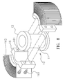
FIG. 8 is a schematic three-dimensional exploded view of a sixth embodiment of the present invention. -
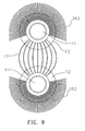
FIG. 9 is a schematic view of a seventh embodiment of the present invention. -
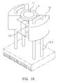
FIG. 10 is a schematic view showing the practice of an eighth embodiment of the present invention. - The present invention relates a
heat dissipation module 10 that can be used for heat dissipation of a microprocessor. Referring to the first embodiment, shown inFIGS. 1 and2 , theheat dissipation module 10 is provided with a heat-conducting column 11 (which is made of a thermal conductive material and can be a heat pipe or a heat column, and which is a heat pipe in this embodiment). The heat -conductingcolumn 11 quickly transfers the temperature from a heat source end to the other end under a specific temperature condition. On at least one end of the heat -conducting column 11 (on the bottom end in this embodiment) is provided an outwardly extending expanded element 12 (which is made of a single or composite thermal conductive material). The end surface of the expandedelement 12 is planar. On the periphery of the heat-conductingcolumn 11 is provided outwardly extending heat-dissipating elements 13 (which are made of a single or composite thermal conductive material and are heat-dissipating blocks or heat-dissipating fins, and which are radial heat-dissipating fins in this embodiment). In such manner, the heat-conductingcolumn 11 and the heat-dissipatingelements 13 not only can allow rapid heat dissipation, but the expandedelement 12 also can enlarge the contact area with a heat-generating source to accelerate heat dissipation. - Referring to
FIG. 3 , there is shown aheat dissipation module 10 that can be used for heat dissipation of a microprocessor or light-emitting diodes, which is the second embodiment of the present invention. This embodiment differs from the first embodiment in that: outwardly extending expandedelements 12 are provided at the two ends of the heat-conductingcolumn 11 respectively and the heat-dissipating elements 13 are disposed between the expandedelements 12 and respectively in contact with the expanded elements, resulting thermal reflux effect, so as to speed up heat dissipation. - Referring to
FIG. 4 , there is shown aheat dissipation module 10 that is used for heat dissipation of light -emitting diodes, which is the third embodiment of the present invention. It differs from the above embodiments in that: on at least one end of the heat-conductingcolumn 11 of theheat dissipation module 10, on the top end in this embodiment, is provided an outwardly extendingexpanded element 12. The end surface of the expandedelement 12 is planar. Light-emitting diodes 14 are disposed on the expandedelement 12. In such manner, the expandedelement 12 enlarges the area to increase the number of light-emitting diodes positioned and accelerate heat dissipation. - Referring to
FIG. 5 , there is similarly shown aheat dissipation module 10 that is used for heat dissipation of light-emitting diodes, which is the fourth embodiment of the present invention. It differs from the third embodiment of the present invention in that: the end surface of the expandedelement 12 is beveled from the outside to the inside (or beveled from the inside to the outside), such that the bevel angle of the expandedelement 12 can improve the effect of collecting light (or diffusing light) when the light-emittingdiodes 14 are mounted thereon. - Referring to
FIG. 6 , there is shown aheat dissipation module 10 that is used for heat dissipation of light -emitting diodes or a microprocessor, which is the fifth embodiment of the present invention. It is provided with a heat-conductingcolumn 11. The heat-conductingcolumn 11 is made of a thermal conductive material, and may be a heat pipe, or may also be a heat column in this embodiment. An outwardly extending expandedelement 12 is provided at one end of the heat-conductingcolumn 11, which is an annular frame in this embodiment. Acollar 15 is disposed on the heat-conductingcolumn 11 and provided with anotch 151. Fixedmembers 152 are respectively provided at the two ends of the notch 151 (which are mutually fitted threaded holes and screws in this embodiment and, however, those skilled in the art can still join them by welding or other means) such that thecollar 15 is secured on the periphery of the heat-conductingcolumn 11 by mutually locking thefixed members 152 when it is put around the heat-conductingcolumn 11. Some region of thecollar 15 is provided with an outwardly developed fan-shaped heat -dissipatingelement 153, such as heat-dissipating fin or heat-dissipating block. In this embodiment, the heat -dissipating element is a heat-dissipating block. The end of the heat-conductingcolumn 11 at which the expandedelement 12 is disposed may be in contact with a heat-generating source when in use. In such manner, the heat-conductingcolumn 11 and the heat-dissipatingelement 153 not only can allow rapid heat dissipation, but the expandedelement 12 also can increase the contact area with the heat-generating source to accelerate heat dissipation. Moreover, further fan-shaped heat -dissipatingelements 153 may be added to thesame collar 15, or more than one of thecollar 15 may be added (as shown inFIG. 7 ), if required. - Referring to the sixth embodiment, shown in
FIG. 8 , the heat dissipation module is provided with a heat -conductingcolumn 11 that is a cylinder in this embodiment. Outwardly extending expandedelements 12 are provided at both two ends of the heat-conductingcolumn 11, each of which is an annular frame in this embodiment. Opposing heat-dissipatingblocks 16 are disposed on the heat -conductingcolumn 11.Fixed members 161 are respectively provided at the two ends of the heat-dissipating blocks 16 (which are mutually fitted threaded holes and screws in this embodiment and, however, those skilled in the art can still join them by welding or other means) such that the heat-dissipatingblocks 16 are clamped on the periphery of the heat-conductingcolumn 11 by mutually locking the fixedmembers 161 when they are attached against the heat -conductingcolumn 11. The peripheries of the heat -dissipatingblocks 16 are respectively provided with outwardly developed fan-shaped heat-dissipatingelements 162. In such manner, the heat-conductingcolumn 11 and the heat-dissipatingelements 162 not only can allow rapid heat dissipation, but the expandedelement 12 also can increase the contact area with the light-emitting diodes to accelerate heat dissipation. - Referring to the seventh embodiment, shown in
FIG. 9 , it is different from each of the above embodiments in that: at least two heat-conductingcolumns 11 are provided and correspond to each other and an outwardly extending heat-dissipating element is provided on the outer side of each of the heat-conductingcolumns 11. Furthermore, aconnection element 17 is provided between the heat -conductingcolumns 11. Theconnection element 17 is made of a thermal conductive material. In such manner, the heat -conductingcolumns 11 are integrated into one piece via theconnection element 17 so as to speedup heat dissipation. - Referring to the eighth embodiment, shown in
FIG. 10 , the heat dissipation module is provided with a heat -conductingcolumn 11 that is a cylinder in this embodiment. Outwardly extending expandedelements 12 are provided at the two ends of the heat-conductingcolumn 11, each of which is an annular frame in this embodiment. Opposing heat-dissipating elements are disposed on the heat -conductingcolumn 11. In this embodiment, the heat -dissipating elements are heat-dissipatingblocks 16.Fixed members 161 are respectively provided at the two ends of the heat-dissipating blocks 16 (which are mutually fitted threaded holes and screws in this embodiment and, however, those skilled in the art can still join them by welding or other means) such that the heat-dissipatingblocks 16 are clamped on the periphery of the heat -conductingcolumn 11 by mutually locking thefixedmembers 161 when they are attached against the heat-conductingcolumn 11. The heat-dissipatingblocks 16 are provided at their end sides with heat-conductingpipes 163 to extend to other spaces or to another heat-dissipating element for heat dissipation.
Claims (13)
- A heat dissipation module comprising:at least one substantially columnar heat-conducting column;at least one hollow expanded element provided at any end of the heat-conducting column; andat least one heat-dissipating element fixed on the periphery of the heat-conducting column.
- The heat dissipation module as claimed in claim 1, wherein the heat-conducting column is a heat pipe.
- The heat dissipation module as claimed in claim 1, wherein the heat-conducting column is a heat column.
- The heat dissipation module as claimed in claim 1, wherein the end surface of the expanded element is a planar surface.
- The heat dissipation module as claimed in claim 1, wherein the end surface of the expanded element is beveled from the outside to the inside.
- The heat dissipation module as claimed in claim 1, wherein the end surface of the expanded element is beveled from the inside to the outside.
- The heat dissipation module as claimed in claim 1, wherein the heat-dissipating element is coupled to a collar mounted around the heat-conducting column.
- The heat dissipation module as claimed in claim 1, wherein the heat-dissipating element is a heat -dissipating block or a heat-dissipating fin.
- The heat dissipation module as claimed in claim 1, wherein two expanded elements are further provided at the two ends of the heat-conducting column respectively and the heat-dissipating element is disposed between the expanded elements.
- The heat dissipation module as claimed in claim 9, wherein the heat-dissipating element is in contact with each of the expanded elements.
- The heat dissipation module as claimed in claim 1, wherein the heat-dissipating element is provided at its end side with a heat-conducting pipe.
- The heat dissipation module as claimed in claim 1, wherein two heat-conducting columns are provided and correspond to each other, an outwardly extending heat -dissipating element is provided on the outer side of each of the heat-conducting columns, and a connection element is provided between the heat-conducting columns.
- The image display method as claimed in claim 12, wherein the connection element is made of a thermal conductive material.
Applications Claiming Priority (1)
| Application Number | Priority Date | Filing Date | Title |
|---|---|---|---|
| TW097210413U TWM348981U (en) | 2008-06-12 | 2008-06-12 | Heat dissipation module |
Publications (2)
| Publication Number | Publication Date |
|---|---|
| EP2133914A2 true EP2133914A2 (en) | 2009-12-16 |
| EP2133914A3 EP2133914A3 (en) | 2012-06-20 |
Family
ID=41090277
Family Applications (1)
| Application Number | Title | Priority Date | Filing Date |
|---|---|---|---|
| EP09007426A Withdrawn EP2133914A3 (en) | 2008-06-12 | 2009-06-04 | Heat dissipation module |
Country Status (3)
| Country | Link |
|---|---|
| US (1) | US20090308575A1 (en) |
| EP (1) | EP2133914A3 (en) |
| TW (1) | TWM348981U (en) |
Cited By (2)
| Publication number | Priority date | Publication date | Assignee | Title |
|---|---|---|---|---|
| WO2011104254A1 (en) * | 2010-02-23 | 2011-09-01 | Zumtobel Lighting Gmbh | Heat sink for a light source |
| FR3035200A1 (en) * | 2015-04-16 | 2016-10-21 | Valeo Vision | BI-MATERIAL HEAT DISSIPER MODULE |
Families Citing this family (12)
| Publication number | Priority date | Publication date | Assignee | Title |
|---|---|---|---|---|
| USD618633S1 (en) * | 2009-07-21 | 2010-06-29 | Foxsemicon Integrated Technology, Inc. | Heat dissipation device |
| USD643380S1 (en) * | 2010-08-12 | 2011-08-16 | Neobulb Technologies, Inc. | Photoelectric energy transducing apparatus |
| TWI407050B (en) * | 2010-11-26 | 2013-09-01 | Univ Chienkuo Technology | Embedded light - emitting diodes metal porous media heat sink |
| USD662898S1 (en) * | 2011-03-24 | 2012-07-03 | Graftech International Holdings Inc. | Heat sink for LED light bulb |
| CN102798103B (en) * | 2011-05-24 | 2016-06-01 | 奥斯兰姆有限公司 | Module radiator for LED |
| US20120314427A1 (en) * | 2011-06-08 | 2012-12-13 | Asia Vital Components Co., Ltd. | Led heat sink and method for manufacturing the same |
| TWM512883U (en) * | 2015-05-05 | 2015-11-21 | 訊凱國際股份有限公司 | Heat dissipation module, water-cooling heat dissipation module and heat dissipation system |
| CN113939160B (en) * | 2021-10-25 | 2024-02-27 | 国网山东省电力公司东营市垦利区供电公司 | A heat dissipation and ventilation device for electric power devices |
| TW202327433A (en) * | 2021-12-28 | 2023-07-01 | 十銓科技股份有限公司 | Structure of uniform temperature heat dissipation device |
| US11920774B2 (en) | 2022-02-01 | 2024-03-05 | Gew (Ec) Limited | LED curing apparatus and cooling module |
| US12196496B2 (en) * | 2022-09-25 | 2025-01-14 | Aic Inc. | Liquid-cooled cooling structure |
| CN119636463B (en) * | 2024-12-31 | 2025-07-11 | 嘉兴市计量检定测试院 | Heat abstractor of new energy automobile fills electric pile |
Family Cites Families (15)
| Publication number | Priority date | Publication date | Assignee | Title |
|---|---|---|---|---|
| US5725050A (en) * | 1996-09-03 | 1998-03-10 | Thermal Corp. | Integrated circuit with taped heat pipe |
| US6851467B1 (en) * | 1999-08-30 | 2005-02-08 | Molex Incorporated | Heat sink assembly |
| US6304451B1 (en) * | 1999-12-01 | 2001-10-16 | Tyco Electronics Logistics Ag | Reverse mount heat sink assembly |
| US6637921B2 (en) * | 2001-09-28 | 2003-10-28 | Osram Sylvania Inc. | Replaceable LED bulb with interchangeable lens optic |
| US6657865B1 (en) * | 2002-12-12 | 2003-12-02 | Wuh Chuong Indutrial Co., Ltd. | Heat dissipating structure |
| US7111667B2 (en) * | 2003-03-31 | 2006-09-26 | Micro-Star Int'l Co., Ltd. | Heat dissipating device |
| US20040264195A1 (en) * | 2003-06-25 | 2004-12-30 | Chia-Fu Chang | Led light source having a heat sink |
| US7497248B2 (en) * | 2004-04-30 | 2009-03-03 | Hewlett-Packard Development Company, L.P. | Twin fin arrayed cooling device |
| US7236366B2 (en) * | 2004-07-23 | 2007-06-26 | Excel Cell Electronic Co., Ltd. | High brightness LED apparatus with an integrated heat sink |
| CN2821749Y (en) * | 2005-07-21 | 2006-09-27 | 新灯源科技有限公司 | Luminous display panel |
| EP1930942A4 (en) * | 2005-09-08 | 2011-03-09 | Neobulb Technologies Inc | STRUCTURE OF HEAT WELL FOR HEATING A COMPONENT |
| CN100518468C (en) * | 2005-10-14 | 2009-07-22 | 鸿富锦精密工业(深圳)有限公司 | Radiator |
| US7303005B2 (en) * | 2005-11-04 | 2007-12-04 | Graftech International Holdings Inc. | Heat spreaders with vias |
| US20070253202A1 (en) * | 2006-04-28 | 2007-11-01 | Chaun-Choung Technology Corp. | LED lamp and heat-dissipating structure thereof |
| US7467878B2 (en) * | 2006-06-06 | 2008-12-23 | Jaffe Limited | Heat-dissipating structure having multiple heat pipes for LED lamp |
-
2008
- 2008-06-12 TW TW097210413U patent/TWM348981U/en not_active IP Right Cessation
-
2009
- 2009-06-04 EP EP09007426A patent/EP2133914A3/en not_active Withdrawn
- 2009-06-09 US US12/481,100 patent/US20090308575A1/en not_active Abandoned
Cited By (3)
| Publication number | Priority date | Publication date | Assignee | Title |
|---|---|---|---|---|
| WO2011104254A1 (en) * | 2010-02-23 | 2011-09-01 | Zumtobel Lighting Gmbh | Heat sink for a light source |
| CN102884376A (en) * | 2010-02-23 | 2013-01-16 | 宗拓贝尔照明器材有限公司 | radiator for light source |
| FR3035200A1 (en) * | 2015-04-16 | 2016-10-21 | Valeo Vision | BI-MATERIAL HEAT DISSIPER MODULE |
Also Published As
| Publication number | Publication date |
|---|---|
| US20090308575A1 (en) | 2009-12-17 |
| TWM348981U (en) | 2009-01-11 |
| EP2133914A3 (en) | 2012-06-20 |
Similar Documents
| Publication | Publication Date | Title |
|---|---|---|
| US20090308575A1 (en) | Heat dissipation module | |
| US20100002453A1 (en) | Illuminating device and annular heat-dissipating structure thereof | |
| US20090040760A1 (en) | Illumination device having unidirectional heat-dissipating route | |
| US20120098402A1 (en) | Led bulb | |
| US8469580B2 (en) | Edge-lighting type backlight module | |
| US20130223061A1 (en) | Multi-layer array type led device having a multi-layer heat dissipation structure | |
| US20130294070A1 (en) | High bay light | |
| TWI397653B (en) | Light-emitting module with cooling function | |
| CN2882200Y (en) | Cooling module | |
| CN101349418A (en) | Radiating module of light-emitting element | |
| CN201314509Y (en) | Heat radiation structure of porous material lampshade | |
| CN201852063U (en) | Lamp cooling device | |
| CN102003650A (en) | Thermotube-radiating-based modular high-power LED lamp assembly | |
| CN101666478A (en) | LED lamp and heat dissipation structure thereof | |
| CN201069139Y (en) | LED lamp device with heat radiation structure | |
| CN201903031U (en) | Cooling module for LED lamps | |
| CN203131511U (en) | Radiator lamps | |
| WO2018133509A1 (en) | Led module and lighting fixture | |
| CN201219345Y (en) | Cooling module | |
| US20110156568A1 (en) | Assembly of heat dissipating module | |
| CN101349413B (en) | LED lamp | |
| CN206386902U (en) | Multi-layer lamp radiating module | |
| CN201772416U (en) | Heat dissipation structure of lamps and lanterns | |
| JP2015198079A (en) | Led lighting device | |
| CN222352190U (en) | High-brightness backlight plate |
Legal Events
| Date | Code | Title | Description |
|---|---|---|---|
| PUAI | Public reference made under article 153(3) epc to a published international application that has entered the european phase |
Free format text: ORIGINAL CODE: 0009012 |
|
| AK | Designated contracting states |
Kind code of ref document: A2 Designated state(s): AT BE BG CH CY CZ DE DK EE ES FI FR GB GR HR HU IE IS IT LI LT LU LV MC MK MT NL NO PL PT RO SE SI SK TR |
|
| PUAL | Search report despatched |
Free format text: ORIGINAL CODE: 0009013 |
|
| AK | Designated contracting states |
Kind code of ref document: A3 Designated state(s): AT BE BG CH CY CZ DE DK EE ES FI FR GB GR HR HU IE IS IT LI LT LU LV MC MK MT NL NO PL PT RO SE SI SK TR |
|
| AX | Request for extension of the european patent |
Extension state: AL BA RS |
|
| RIC1 | Information provided on ipc code assigned before grant |
Ipc: F28D 15/02 20060101ALI20120515BHEP Ipc: H01L 23/427 20060101AFI20120515BHEP Ipc: F28F 1/14 20060101ALI20120515BHEP Ipc: H01L 23/367 20060101ALI20120515BHEP Ipc: F28F 1/20 20060101ALI20120515BHEP |
|
| STAA | Information on the status of an ep patent application or granted ep patent |
Free format text: STATUS: THE APPLICATION IS DEEMED TO BE WITHDRAWN |
|
| 18D | Application deemed to be withdrawn |
Effective date: 20121221 |