EP2538832B1 - A fundus camera - Google Patents
A fundus camera Download PDFInfo
- Publication number
- EP2538832B1 EP2538832B1 EP11702007.3A EP11702007A EP2538832B1 EP 2538832 B1 EP2538832 B1 EP 2538832B1 EP 11702007 A EP11702007 A EP 11702007A EP 2538832 B1 EP2538832 B1 EP 2538832B1
- Authority
- EP
- European Patent Office
- Prior art keywords
- retina
- projecting
- patient
- regulating
- light
- Prior art date
- Legal status (The legal status is an assumption and is not a legal conclusion. Google has not performed a legal analysis and makes no representation as to the accuracy of the status listed.)
- Active
Links
- 210000001525 retina Anatomy 0.000 claims description 78
- 230000001105 regulatory effect Effects 0.000 claims description 61
- 238000000034 method Methods 0.000 claims description 42
- 238000012545 processing Methods 0.000 claims description 26
- 230000001360 synchronised effect Effects 0.000 claims description 21
- 230000003213 activating effect Effects 0.000 claims 1
- 210000000695 crystalline len Anatomy 0.000 description 46
- 230000003287 optical effect Effects 0.000 description 24
- 230000006870 function Effects 0.000 description 10
- 238000004519 manufacturing process Methods 0.000 description 8
- 210000001747 pupil Anatomy 0.000 description 7
- 210000004204 blood vessel Anatomy 0.000 description 5
- 230000007547 defect Effects 0.000 description 5
- 239000011159 matrix material Substances 0.000 description 5
- 230000009467 reduction Effects 0.000 description 5
- 238000004458 analytical method Methods 0.000 description 4
- 238000006073 displacement reaction Methods 0.000 description 4
- 210000004087 cornea Anatomy 0.000 description 3
- 206010020675 Hypermetropia Diseases 0.000 description 2
- 230000004075 alteration Effects 0.000 description 2
- 238000013461 design Methods 0.000 description 2
- 230000004305 hyperopia Effects 0.000 description 2
- 201000006318 hyperopia Diseases 0.000 description 2
- 208000001491 myopia Diseases 0.000 description 2
- 230000004379 myopia Effects 0.000 description 2
- 230000002093 peripheral effect Effects 0.000 description 2
- 230000008859 change Effects 0.000 description 1
- 230000002860 competitive effect Effects 0.000 description 1
- 238000004590 computer program Methods 0.000 description 1
- 238000012937 correction Methods 0.000 description 1
- 239000006185 dispersion Substances 0.000 description 1
- 238000003780 insertion Methods 0.000 description 1
- 230000037431 insertion Effects 0.000 description 1
- 230000007246 mechanism Effects 0.000 description 1
- 230000008569 process Effects 0.000 description 1
Images


Classifications
-
- A—HUMAN NECESSITIES
- A61—MEDICAL OR VETERINARY SCIENCE; HYGIENE
- A61B—DIAGNOSIS; SURGERY; IDENTIFICATION
- A61B3/00—Apparatus for testing the eyes; Instruments for examining the eyes
- A61B3/10—Objective types, i.e. instruments for examining the eyes independent of the patients' perceptions or reactions
- A61B3/12—Objective types, i.e. instruments for examining the eyes independent of the patients' perceptions or reactions for looking at the eye fundus, e.g. ophthalmoscopes
Definitions
- the present invention relates to the field of equipment for inspecting the ocular fundus.
- the present invention refers to an apparatus for inspecting the ocular fundus that affords an improved performance inasmuch as concerns the procedure for focusing on the patient's retina.
- fundus cameras are used to inspect the ocular fundus.
- a fundus camera optically conjugates the pupil of the eye with a ring-shaped light source.
- the eye is illuminated by a light beam that has a ring-shaped cross section on a level with the pupil and the light reflected by the retina is received, through the central portion of the pupil, by suitable sensor means designed to enable the retina to be observed and photographed.
- a fundus camera Before starting an examination, a fundus camera must typically complete a procedure for focusing on the retina, so as to enable an optimal view of the latter.
- focusing is used hereinafter to mean a set of steps designed to optically conjugate the above-mentioned sensor means with the patient's retina, adjusting for any refractory defects of the eye being examined, e.g. myopia or hypermetropia.
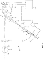
- FIG. 1 is a schematic illustration of a fundus camera 100 of known type.
- the camera 100 comprises an illuminator device 101 capable of emitting a ring-shaped light beam 121.
- the light 121 emitted by the ring-shaped area 102 of the illuminator 101 is collimated in an area approximately coinciding with the centre of the perforated mirror 105 by means of a system of lenses 103 and 104.
- the light beam 121 is reflected by the mirror 105 and collimated by means of the lens 106 on a point situated approximately on the plane of the pupil 7A of the eye 7, until it comes to illuminate the retina 7B.
- the light reflected by the retina 7B passes through the central area of the pupil 7A and is oriented by the lens 106 towards the hole in the mirror 105, and then collimated by means of a set of lenses 109 to form an image on a receiving surface of the sensor 110, for example a digital camera.
- first opaque disc 111 which intercepts the portions of light beam that might be reflected on the crystalline lens of the eye 7
- second opaque disc 112 which intercepts the light that could give rise to reflections on the cornea of the eye 7.
- the camera 100 comprises an emitter device 113, consisting of an infrared light source, one or more perforated masks, lenses and microprisms (not shown) for emitting a plurality of light beams 114 designed to generate a pattern of luminous lines on the retina.
- an emitter device 113 consisting of an infrared light source, one or more perforated masks, lenses and microprisms (not shown) for emitting a plurality of light beams 114 designed to generate a pattern of luminous lines on the retina.
- the light beams 114 are inserted in the optical path of the camera 100 by means of a movable mirror 115 or, alternatively, a beam splitting device (not shown).
- the emitter device 113 is operatively associated with the set of lenses 109, by means of a mechanical connection 138, such that any movement of the emitter 113 is mechanically synchronised with the movement of the whole set of lenses 109, or with the movement of one lens 910 in said set of lenses 109.
- the luminous lines projected onto the retina by the light beam 114 are visible directly on the image returned by the sensor 110, or through an eyepiece operatively associated with a system of lenses and beam splitting devices (not shown).
- a plurality of unaligned luminous lines is projected onto the retina.
- the emitter device 113 and the set of lenses 109 are moved in a synchronous manner to align the luminous lines observable on the retina.
- the fundus camera of conventional type as illustrated in Figure 1 , has some drawbacks.
- the movable mirror 115 may suffer from wear and tear after a relatively large number of usage cycles, with a negative fallout on the accuracy of its insertion in the optical path of the camera 100.
- the camera 100 is suitable for being focused manually by a human operator looking through an eyepiece.
- any focusing procedure must necessarily involve steps for identifying the shape and position of the luminous lines projected onto the retina.
- Such identification procedures are generally not very reliable, e.g. in cases where two luminous lines are near the position of alignment, or when the shape of the retina determines a change in the shape of the luminous lines.
- the procedure for focusing the camera 100 is consequently difficult to implement with the aid of a software that enables it to be done automatically.
- the main technical aim of the present invention is thus to provide a fundus camera that enables the above-mentioned drawbacks of the known art to be overcome.
- one object of the present invention is to provide a fundus camera that enables a simple and reliable focusing procedure to be completed easily and automatically by means of software.
- Another object of the present invention is to provide a fundus camera characterised in that it is extremely simple to manufacture and of limited overall dimensions.
- Another object of the present invention is to provide a fundus camera that is easy to manufacture industrially at competitive prices.
- the fundus camera comprises illuminating means that project a first light beam to illuminate the retina of a patient's eye and that comprise one or more first light sources, preferably a plurality of LED (Light Emitting Diodes) devices.
- illuminating means that project a first light beam to illuminate the retina of a patient's eye and that comprise one or more first light sources, preferably a plurality of LED (Light Emitting Diodes) devices.
- the illuminating means comprise a shaped structure provided with a through hole.
- the first light sources of the illuminating means are preferably arranged on said shaped structure, advantageously in a region around said through hole, so that the illuminating means emit a substantially ring-shaped light beam.
- the fundus camera according to the invention comprises projecting means that project one or more second light beams onto the retina, said projecting means comprising one or more second light sources.
- the projecting means comprise an infrared light source, e.g. at least one infrared LED device, and an opaque mask with one or more holes for enabling the passage of the light emitted by said infrared light source.
- an infrared light source e.g. at least one infrared LED device
- an opaque mask with one or more holes for enabling the passage of the light emitted by said infrared light source.
- the projecting means preferably also comprise a collimating lens positioned between the infrared light source and the opaque mask, and advantageously arranged so as to afford a relatively high spherical aberration.
- the fundus camera according to the invention also comprises sensor means designed to receive the light reflected from the retina onto a receiving surface and thus acquire one or more images of the retina, and means for regulating the focusing of the images of the retina on a level with the receiving surface of said sensor means.
- actuating means designed to move said regulating means and said projecting means, as well as processing means that analyse the images of the retina acquired by said sensor means and generate control signals for said actuating means.
- the projecting means of the fundus camera are arranged coaxially to the illuminating means, along a same axis (a), and project said second light beams through at least a lens that is kept in position by means of a hollow body, which is operatively associated to the through hole of the shaped structure of the illuminating means of the fundus camera.
- the projecting means can thus project the second light beams through the hole in the shaped structure of said illuminating means, which supports the first light sources of said illuminating means.
- the processing means may calculate data indicative of the maximum light intensity values in one or more images of the retina and, on the strength of the data thus calculated, to generate control signals for said actuating means in order to move said regulating means into a focused position, coinciding with which the retina is optically conjugated with the receiving surface of said sensor means.
- the data indicative of the maximum light intensity values preferably comprise a characteristic index of the points of maximum light intensity in one or more images of the retina.
- said processing means complete a procedure that comprises at least the following steps:
- the regulating means and projecting means are operatively connected to one another by means of a kinematic chain and can advantageously be moved by a same first actuating device.
- the above-mentioned actuating means may comprise a second actuating device for moving the regulating means, and a third actuating device for moving the projecting means.
- Another aspect of the present invention relates to a method for focusing the fundus camera on the retina of the patient's eye, which comprises the following steps:
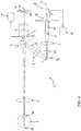
- the present invention refers to a fundus camera 1.
- the camera 1 comprises: illuminating means 13, for projecting a first light beam (not shown) to illuminate the retina 7B of a patient's eye 7; projecting means 17, for projecting one or more second light beams 21 onto the retina; sensor means 10, for receiving the light reflected from the retina onto a receiving surface 10A, to acquire one or more images of the retina; and regulating means for adjusting the focus of the images of the retina in line with the receiving surface 10A of the sensor means 10.
- the regulating means may, for instance, comprise a movable set of lenses 9 or, preferably, as shown in figures 2-4 , a single movable lens 91 in a group of lenses 9.
- the camera 1 also comprises actuating means designed to move the regulating means 91 and the projecting means 17.
- the actuating means in the camera 1 may comprise a first actuating device 260, preferably consisting of a linear actuator with a stepping motor ( figure 2 ).
- the actuating means in the camera 1 may comprise a second actuating device 26, for moving only the regulating means 91, and a third actuating device 28, for moving only the projecting means 17.
- the actuating devices 26 and 28 also preferably consist of linear actuators with stepping motors.
- processing means 37 for analysing the images of the retina acquired by the sensor means 10, and for generating control signals for the above-mentioned actuating means 260, 26, 28.
- the illuminating means 13 comprise a one or more first light sources (preferably a plurality of LED devices), which are arranged so that the first light beam emitted by the illuminating means is substantially ring-shaped.
- the illuminating means comprise a shaped structure 16A for supporting the first light sources, which comprises a through hole 16, around which the first light sources are preferably arranged.
- the shaped structure 16A preferably comprises an electronic card operatively associated with a light concentrating device with a ring-shaped outlet of the type described in the Italian patent application No. TV2009A000201 .
- the shaped structure 16A may be shaped differently from the one described above.
- the first light beam emitted by the illuminating means 13 follows an optical path entirely similar to the one described for the camera in figure 1 .
- the first light beam is collimated by means of the lenses 3 and 4 in line with an area that roughly coincides with the centre of a perforated mirror 5.
- the first light beam is thus reflected by the mirror 5 along the optical axis (b), and subsequently collimated by means of the one or more lenses 6 at a point situated approximately on the plane of the pupil 7A of the eye 7, thus coming to illuminate the retina 7B.
- the light reflected by the retina 7B passes through the central area of the pupil 7A, and is oriented by the lens 6 towards the hole, then it is collimated by means of the set of lenses 9 to form an image on a receiving surface 10A of the sensor means 10, consisting of a digital camera, for instance.
- a mask 12 designed to intercept the light that might give rise to reflections on the cornea of the eye 7.
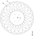
- the projecting means 17 project a plurality of second light beams onto the retina.
- They comprise one or more second light sources, preferably at least one infrared light source 18 that can advantageously consist of at least one infrared LED device.
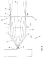
- the infrared light source 18 is advantageously associated operatively with an opaque mask 20, with one or more holes 35 that are arranged on a circular zone of the mask to enable the passage of the light 32 emitted by the source 18 ( figures 5-6 ).
- the projecting means 17 preferably also comprise an intermediate lens 19 positioned between the infrared light source 18 and the opaque mask 20.
- the light 32, emitted from the emission surface 30 of the source 18, is advantageously collimated by means of the lens 19 onto the mask 20.
- the lens 19 is mounted so that it has a first surface 19A with a lesser radius facing towards the light source 18, and a second surface 19B with a greater radius facing towards the mask 20.
- the diversion of the light rays 33 coming to bear on the peripheral area of the lens 19 is thus greater than the diversion of the light rays 34 coming to bear on areas closer to the centre of the lens 19.
- intersection area 30A in the form of a circular crown, situated a certain distance from the lens 19.
- the power density of the light beam 32 emitted by the source 18 reaches its maximum peak in this intersection area 30A.
- the mask 20 is advantageously positioned substantially at said intersection area 30A, with the holes 35 arranged in a substantially circular pattern, the diameter of said circle advantageously corresponding to the diameter of the intersection area 30A.
- the light rays 32 diverted by the lens 19 advantageously converge before the outer edge 35A of the holes 35 in the mask 20.
- the light beams 21 emerging from the holes 35 consequently diverge as if they were generated by independent light sources located in line with the holes 35.
- the light coming from the projecting means 17 is thus entirely similar to the light created by a plurality of independent sources, each designed to emit a light beam 21.
- the intermediate lens 19 is preferably a plano-convex lens. This enables a further cost reduction while obtaining good-quality light beams 21 emerging from the holes 35 in the mask 20.
- the projecting means 17 are arranged coaxially to the illuminating means 13, along the same optical axis (a) as the latter.
- the projecting means 17 are advantageously arranged so that they project the light beams 21 through the hole 16 in the supporting structure 16A for the illuminating means 13.
- the projecting means 17 comprise a collimation lens 23 and a hollow body 24.
- the light beams 21 pass through the collimation lens 23, which is supported and maintained in a position coaxial to the illuminating means 13 by the hollow body 24, which is operatively associated with the through hole 16 of the shaped structure 16A.
- the hollow body 24 is preferably in the shape of a cylindrical or conical tube that is operatively associated with the through hole 16 at an end that is opposite to the one in which the lens 23 is located.
- the walls of the hollow body 24 are advantageously capable of intercepting the light generating reflections on the crystalline lens of the eye 7.
- the light beams 21 then pass through the further collimation lens 3 and is collimated on a plane (r) optically conjugated with the retina 7B.
- the light 21 advantageously enters the optical path of the camera 1, coaxially to the through hole 16, without any need to use movable mirrors or beam splitting devices.
- the projecting means 17 could be mounted inside the hollow body 24.
- the position of the projecting means 17 along the optical axis (a) might possibly be adjusted by means of a rod passing through the hole 16.
- the image of the retina with the above-mentioned matrix of luminous points 25 can be viewed and acquired by the sensor means 10.
- Figure 4 shows a possible variant of the present invention, in which a mirror 29 is inserted along the optical path, between the illuminating means 13 and the perforated mirror 5.
- This mirror 29 is advantageously designed to reflect the first light beam emitted by the illuminating means 13, and/or the second light beams 21 emitted by the projecting means 17.
- the introduction of the mirror 29 enables the optical path between the illuminating means 13 and the perforated mirror 5 to be bent along the optical axis (a).
- the processing means 37 consisting of a computer executing one or more computer programs, for instance, are designed to calculate indicative data of the maximum light intensity values in one or more images of the retina acquired by the sensor means 10.
- the processing means 37 On the base of the data thus calculated, the processing means 37 generate control signals for the actuating means 260, 26 and 38 in order to move the regulating means 91 into a focusing position X F , coinciding with which the retina is optically conjugated with the receiving surface 10A of the sensor means 10.
- the data indicating the distribution of the light intensity preferably comprise the same number of maximum light intensity values in the images of the retina as the number of the second beams 21 projected onto the retina.
- the processing means 37 preferably execute a procedure that involves measuring the focusing of the camera 1, analysing a series of images of the retina showing the matrix of luminous points generated by the light beams 21 emitted by the projecting means 17, each of said images corresponding to a certain position X of the regulating means 91, along the axis (b).
- the procedure executed by the processing means 37 comprises a step (i), in which the processing means analyse an image of the retina acquired by the sensor means 10, and a step (ii), in which the processing means determine a number points of maximum light intensity in said image of the retina, which is equal to the number of second light beams projected by the projecting means 17.
- step (iii) After establishing the points of maximum light intensity in the image acquired, there is a step (iii) in which a value V I of a characteristic index I of the points of maximum light intensity is calculated, e.g. the arithmetic mean of the values of maximum light intensity corresponding to the points of maximum light intensity found in the previous step (ii).
- step (iv) for storing the value V I of the characteristic index I calculated in step (iii), and the corresponding position X of the regulating means 91, along the optical axis (b).
- step (v) in which the processing means generate control signals for the actuating means 260, 26, 28, in order to move the regulating means 91 and the projecting means 17 in a synchronised manner and with a predefined step.
- the trend of the characteristic index I can be reconstructed by identifying a suitable curve that interpolates the set of values V I calculated for each repetition of the cycle consisting of the previous steps (i) to (v), and for each image acquired.
- the processing means calculate the maximum value I MAX of the characteristic index I, and a step (viii) generate control signals for the actuating means 260, 26, 28, in order to move the regulating means 91 into the position X F , coinciding with which said characteristic index I acquires the maximum value I MAX .
- the procedure executed by the processing means 37 to focus the camera 1 exploits the fact that the luminous intensity of the points 25 projected onto the retina correlates with the state of collimation of the light beams 21.
- the luminous intensity of the points 25 projected onto the retina increases as a function of the degree of collimation of the light beams 21, reaching the maximum values when the light beams 21 are focused on the retina.
- the procedure completed by the processing means 37 involves calculating a characteristic index I indicative of the points of maximum light intensity on the pixels of the acquired image ( figure 8 ).
- This characteristic index I reaches its maximum value I MAX for a position X F of the regulating means 91, coinciding with which the power of the light beams 21 is distributed over a minimum area, i.e. when the light beams 21 are collimated on the retina.
- the regulating means 91 move in a synchronised manner with the emitter 17, the retina is also optically conjugated with the receiving surface 10A of the sensor means 10.
- the camera 1 is focused when the regulating means 91 are in the position X F .
- the power density could drop when the luminous point is collimated on an area of narrower diameter than that of the blood vessel.
- Projecting a matrix of luminous points reduces the probability of all of the points collimated coinciding with blood vessels or defects of the retina, and the procedure for analysing the images of the retina consequently becomes more reliable.
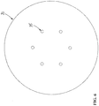
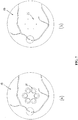
- the luminous points 25 generally appear as blurred ring-shaped patches of light 27, with a central area that is not illuminated ( figure 7 - image (A)).
- the plane conjugated with the sensor means 10, where the light beams 21 are collimated does not coincide with the surface of the retina.
- the ring shape of the patches of light 27 is substantially due to the presence of the mask 12 along the optical path that not only intercepts the light that would be reflected on the cornea and from there onto the sensor means 10, it also intercepts the central portion of the light beams 21 that generate the luminous points 25.
- the ring-shaped cross-section of the light beams 21 facilitates an increase in the variation of the light intensity on the pixels of the receiving surface 10A of the sensor means 10 during the search for the position of maximal collimation, thus making the focusing procedure more precise.
- the processing means 37 could advantageously measure the power density of the pixels on the receiving surface 10A in line with a certain number of software windows centred with the nominal position of the luminous points 25, thus avoiding the need to analyse the whole image acquired by the sensor means 10.
- a further aspect of the invention clearly concerns a method for focusing the fundus camera 1.
- the above focusing method involves at least the following steps:
- the regulating means 91 and the projecting means 17 are operatively connected together by a kinematic chain 38, which may consist, for instance, of a system of levers or a cam mechanism.
- the kinematic chain 38 is operatively connected to the one actuating device 260, which can thus adjust the position X of the regulating means 91 along the axis (b) in a manner synchronised with the position Y of the projecting means 17 along the axis (a).
- the camera 1 can comprise the independent actuating devices 26 and 28, and controlled by the processing means 17 in order to move the regulating means 91 and projecting means 17 in a synchronised manner.
- the synchronised displacement of the regulating means 91 and of the projecting means 17 is clearly obtained not mechanically, by means of a kinematic chain connecting the parts in motion to one another, but by a software program executed by the processing means 37.
- the optics for the camera 1 can be designed virtually independently from the design of the mechanical parts, enabling a reduction in the time and cost of designing or modifying the camera 1.
- the tolerances of the mechanical and optical parts can consequently be increased without affecting the operation of the camera 1, thus enabling a reduction in its overall costs.
- the above-described calibration procedure involves a first step (a) of providing a calibration instrument comprising a lens 363 and a moving target 362, coaxial to the lens 363.
- the axial position of the target 362 in relation to the lens 363 can be adjusted by means of a fourth actuating device 361, consisting of a linear actuator with a stepping motor, for instance, advantageously controlled by the processing means 37.
- the surface of the target 362 has a high-contrast pattern 365, such as a number of repeated geometrical figures consisting of black lines on a white background ( figure 10 ).
- the pattern 365 is advantageous for focusing the sensor means 10 during the calibration process, using algorithms of known type that identify the clearest image from among a series of images obtained.
- the light beams 21, emitted by the projecting means 17, are advantageously projected onto the central part of the target 362, generating the luminous points 366.
- the central part of the target 362 is advantageously of only one colour (e.g. white) to facilitate the identification of the local peak intensities of the luminous points projected during the calibration procedure.
- the target 362 can be illuminated with the illuminating means 13 or by means of any other illuminator device 364, incorporated in the calibration instrument 36.
- the calibration procedure then involves a step (b) for fitting the calibration instrument 36 in a predefined position in relation to the lens 6, i.e. in front of the latter.
- step (c) for preparing the actuating means 26 and 28, and the actuating device 361 in a zero starting position, followed by a step (d) for illuminating the target 362 and deactivating the projecting means 17.
- the target 362 can be illuminated with the light beam normally used by the illuminating means 13 to illuminate the retina or, preferably, with a light beam generated by means of the illuminator device 364.
- Adopting the illuminator device 364 avoids the need to make the light pass through the lenses in the objective lens 363. This eliminates any risk of reflections of this light being generated on the lenses of the objective 363.
- the calibration procedure also involves a step (e) for acquiring first images of the target 362 for different positions X of the regulating means 91 along the axis (b), with the aid of the sensor means 10.
- step (g) of the calibration procedure the illuminating means 13 or illuminator device 364 are deactivated and the projecting means 17 are activated.
- step (h) the sensor means 10 acquire second images of the target 362 for different positions Y of the projecting means 17 along the axis (a), while maintaining the regulating means 91 in the position Xi.
- step (i) the calibration procedure involves identifying the points of maximum light intensity for each of the second images acquired and calculating a characteristic index I of said points of maximum light intensity.
- step (j) for calculating the maximum value I MAX of said characteristic index
- step (k) for identifying and storing the position (Yi) of the projecting means 17 coinciding with which the characteristic index acquires said maximum value
- step (1) for storing the pair of positions (Xi, Yi).
- step (m) the procedure involves moving the target 362 with a predefined step by means of the fourth actuating device 361.
- step (n) all the previous steps from (d) to (m) are repeated at least once.
- the camera 1 according to the invention has considerable advantages over the known art.
- the procedure for focusing the camera 1 is very straightforward and reliable.
- the projection of a plurality of luminous points onto the retina ensures that the results are virtually unaffected by any local defects of the retina or any presence of blood vessels.
- the focusing procedure is consequently easy to complete automatically with the aid of suitable software, which can be run by the processing means 37.
- the camera 1 is characterised by a marked structural simplicity.
- the projecting means 17 have a relatively straightforward structure and do not comprise any complex systems of microprisms and lenses for generating the light beams 21.
- the light beams 21 emitted by the projecting means 17 are inserted in the optical path without using movable mirrors or beam splitting devices.
- the camera 1 can easily be adjusted by means of a preset calibration procedure that enables the risk of human error to be reduced and also contains the time and cost of the camera's manufacture.
- the camera 1 is very compact and is of relatively limited weight and overall dimensions.
- the camera 1 is globally of relatively straightforward structural design, easy to manufacture on an industrial scale, and offers considerable advantages in terms of contain production costs.
Landscapes
- Life Sciences & Earth Sciences (AREA)
- Health & Medical Sciences (AREA)
- Medical Informatics (AREA)
- Biophysics (AREA)
- Ophthalmology & Optometry (AREA)
- Engineering & Computer Science (AREA)
- Biomedical Technology (AREA)
- Heart & Thoracic Surgery (AREA)
- Physics & Mathematics (AREA)
- Molecular Biology (AREA)
- Surgery (AREA)
- Animal Behavior & Ethology (AREA)
- General Health & Medical Sciences (AREA)
- Public Health (AREA)
- Veterinary Medicine (AREA)
- Eye Examination Apparatus (AREA)
Applications Claiming Priority (2)
| Application Number | Priority Date | Filing Date | Title |
|---|---|---|---|
| IT000025A ITTV20100025A1 (it) | 2010-02-25 | 2010-02-25 | Apparato d'ispezione del fondo oculare e procedimento relativo |
| PCT/EP2011/051135 WO2011104062A2 (en) | 2010-02-25 | 2011-01-27 | A fundus camera |
Publications (2)
| Publication Number | Publication Date |
|---|---|
| EP2538832A2 EP2538832A2 (en) | 2013-01-02 |
| EP2538832B1 true EP2538832B1 (en) | 2017-09-20 |
Family
ID=42735283
Family Applications (1)
| Application Number | Title | Priority Date | Filing Date |
|---|---|---|---|
| EP11702007.3A Active EP2538832B1 (en) | 2010-02-25 | 2011-01-27 | A fundus camera |
Country Status (7)
| Country | Link |
|---|---|
| US (1) | US9078602B2 (enExample) |
| EP (1) | EP2538832B1 (enExample) |
| JP (1) | JP5753201B2 (enExample) |
| AU (1) | AU2011220014B2 (enExample) |
| CA (1) | CA2789042A1 (enExample) |
| IT (1) | ITTV20100025A1 (enExample) |
| WO (1) | WO2011104062A2 (enExample) |
Families Citing this family (6)
| Publication number | Priority date | Publication date | Assignee | Title |
|---|---|---|---|---|
| JP6173169B2 (ja) * | 2012-11-26 | 2017-08-02 | キヤノン株式会社 | 眼科装置及び眼科装置の制御方法 |
| ITFI20130229A1 (it) * | 2013-10-02 | 2015-04-03 | Strumenti Oftalmici C S O S R L Costruzioni | Apparato e metodo per la misura di aberrazioni del sistema ottico di un essere vivente |
| WO2017100685A1 (en) | 2015-12-10 | 2017-06-15 | Bioxytech Retina, Inc. | Methods and apparatus for measuring blood oxygenation of tissue |
| US11395589B2 (en) | 2017-03-31 | 2022-07-26 | Carl Zeiss Meditec, Inc. | Systems and methods for characterizing refraction with ophthalmic imaging systems |
| EP3941333A1 (en) | 2019-03-20 | 2022-01-26 | Carl Zeiss Meditec, Inc. | A patient tuned ophthalmic imaging system with single exposure multi-type imaging, improved focusing, and improved angiography image sequence display |
| US12490923B2 (en) | 2020-12-31 | 2025-12-09 | Bioxytech Retina, Inc. | Methods and devices for measuring structural and functional properties of tissue |
Family Cites Families (19)
| Publication number | Priority date | Publication date | Assignee | Title |
|---|---|---|---|---|
| JPS5663330A (en) * | 1979-10-25 | 1981-05-29 | Canon Kk | Inspecting machine for eye |
| JPH02268727A (ja) * | 1989-04-10 | 1990-11-02 | Kowa Co | 眼科測定方法及び装置 |
| US5268922A (en) * | 1991-10-31 | 1993-12-07 | International Business Machines Corporation | Laser diode assembly |
| JP3630887B2 (ja) * | 1996-10-31 | 2005-03-23 | 株式会社ニデック | 手持ち型眼底カメラ |
| US6337993B1 (en) * | 1997-02-27 | 2002-01-08 | Canon Kabushiki Kaisha | Blood flow measuring apparatus |
| US6027216A (en) * | 1997-10-21 | 2000-02-22 | The Johns University School Of Medicine | Eye fixation monitor and tracker |
| GB0003333D0 (en) * | 2000-02-15 | 2000-04-05 | Marshall Ian | Ophthalmoscope optical system |
| US20030157464A1 (en) * | 2002-02-20 | 2003-08-21 | Cesare Tanassi | Instrument for eye examination and method |
| US7052134B2 (en) * | 2003-05-29 | 2006-05-30 | Nidek Co., Ltd. | Fundus camera |
| EP1850731A2 (en) * | 2004-08-12 | 2007-11-07 | Elop Electro-Optical Industries Ltd. | Integrated retinal imager and method |
| EP1809162B1 (en) * | 2004-11-08 | 2015-07-01 | Optovue, Inc. | Optical apparatus and method for comprehensive eye diagnosis |
| JP4843242B2 (ja) * | 2005-03-31 | 2011-12-21 | 株式会社トプコン | 眼底カメラ |
| US7703922B2 (en) | 2005-07-15 | 2010-04-27 | Jozef F Van de Velde | Relaxed confocal catadioptric scanning laser ophthalmoscope |
| JP4776450B2 (ja) * | 2006-06-16 | 2011-09-21 | 株式会社トプコン | 眼科撮影装置 |
| JP5117396B2 (ja) * | 2006-11-24 | 2013-01-16 | 株式会社ニデック | 眼底撮影装置 |
| JP4878277B2 (ja) * | 2006-11-29 | 2012-02-15 | キヤノン株式会社 | 眼科撮影装置及び該眼科撮影装置に使用するフォーカスユニット |
| WO2008101359A1 (en) * | 2007-02-23 | 2008-08-28 | Mimo Ag | Ophthalmologic apparatus for imaging an eye by optical coherence tomography |
| US7837329B2 (en) * | 2008-03-31 | 2010-11-23 | Nidek Co., Ltd. | Fundus camera |
| JP5173569B2 (ja) * | 2008-05-09 | 2013-04-03 | キヤノン株式会社 | 眼科装置 |
-
2010
- 2010-02-25 IT IT000025A patent/ITTV20100025A1/it unknown
-
2011
- 2011-01-27 AU AU2011220014A patent/AU2011220014B2/en active Active
- 2011-01-27 EP EP11702007.3A patent/EP2538832B1/en active Active
- 2011-01-27 WO PCT/EP2011/051135 patent/WO2011104062A2/en not_active Ceased
- 2011-01-27 CA CA2789042A patent/CA2789042A1/en not_active Abandoned
- 2011-01-27 JP JP2012554258A patent/JP5753201B2/ja active Active
- 2011-01-27 US US13/580,887 patent/US9078602B2/en active Active
Non-Patent Citations (1)
| Title |
|---|
| None * |
Also Published As
| Publication number | Publication date |
|---|---|
| WO2011104062A2 (en) | 2011-09-01 |
| JP5753201B2 (ja) | 2015-07-22 |
| US9078602B2 (en) | 2015-07-14 |
| AU2011220014B2 (en) | 2015-07-02 |
| US20130010261A1 (en) | 2013-01-10 |
| AU2011220014A1 (en) | 2012-08-30 |
| JP2013520254A (ja) | 2013-06-06 |
| EP2538832A2 (en) | 2013-01-02 |
| ITTV20100025A1 (it) | 2011-08-26 |
| WO2011104062A3 (en) | 2013-01-10 |
| CA2789042A1 (en) | 2011-09-01 |
Similar Documents
| Publication | Publication Date | Title |
|---|---|---|
| EP2538832B1 (en) | A fundus camera | |
| EP2630908B1 (en) | Imaging apparatus | |
| US7281800B2 (en) | Device and method for imaging, stimulation, measurement and therapy, in particular for the eye | |
| KR20030036683A (ko) | 동기 맵핑을 위한 방법 및 장치 | |
| EP2422691A1 (en) | Ophthalmologic device | |
| JPH0366355A (ja) | トポグラフィ測定方法とその装置 | |
| JP5038703B2 (ja) | 眼科装置 | |
| JP2004033744A (ja) | 携帯型の眼科装置用の調整システム | |
| EP3190949B1 (en) | Scanning perimeter | |
| EP2879564B1 (en) | Apparatus for detecting ocular defects | |
| US20140132918A1 (en) | Ophthalmologic apparatus and method | |
| US20060215112A1 (en) | Eye's optical characteristics measuring system | |
| JP5566711B2 (ja) | 眼科装置 | |
| JP7607099B2 (ja) | 眼科装置 | |
| US20060256286A1 (en) | Eye's optical characteristics measuring system | |
| JP6077777B2 (ja) | 眼科装置及び眼科装置のアライメント方法 | |
| US20250352056A1 (en) | Ophthalmic apparatus and ophthalmic information processing apparatus | |
| JP6761504B2 (ja) | 視機能検査装置 | |
| JP6761503B2 (ja) | 視機能検査装置 | |
| JP2024101291A (ja) | 眼科測定装置 | |
| JP2024101292A (ja) | 眼科測定装置 | |
| JP2024101520A (ja) | 眼科測定装置 | |
| JP6633939B2 (ja) | 検査装置 | |
| WO2024154480A1 (ja) | 眼科測定装置 | |
| DE102017115501B4 (de) | Technik zum automatischen Ausrichten eines Beleuchtungsfeldes einer ophthalmologischen Untersuchungseinrichtung |
Legal Events
| Date | Code | Title | Description |
|---|---|---|---|
| PUAI | Public reference made under article 153(3) epc to a published international application that has entered the european phase |
Free format text: ORIGINAL CODE: 0009012 |
|
| 17P | Request for examination filed |
Effective date: 20120810 |
|
| AK | Designated contracting states |
Kind code of ref document: A2 Designated state(s): AL AT BE BG CH CY CZ DE DK EE ES FI FR GB GR HR HU IE IS IT LI LT LU LV MC MK MT NL NO PL PT RO RS SE SI SK SM TR |
|
| R17D | Deferred search report published (corrected) |
Effective date: 20130110 |
|
| DAX | Request for extension of the european patent (deleted) | ||
| GRAP | Despatch of communication of intention to grant a patent |
Free format text: ORIGINAL CODE: EPIDOSNIGR1 |
|
| INTG | Intention to grant announced |
Effective date: 20170223 |
|
| GRAJ | Information related to disapproval of communication of intention to grant by the applicant or resumption of examination proceedings by the epo deleted |
Free format text: ORIGINAL CODE: EPIDOSDIGR1 |
|
| GRAP | Despatch of communication of intention to grant a patent |
Free format text: ORIGINAL CODE: EPIDOSNIGR1 |
|
| INTC | Intention to grant announced (deleted) | ||
| INTG | Intention to grant announced |
Effective date: 20170503 |
|
| GRAS | Grant fee paid |
Free format text: ORIGINAL CODE: EPIDOSNIGR3 |
|
| GRAA | (expected) grant |
Free format text: ORIGINAL CODE: 0009210 |
|
| AK | Designated contracting states |
Kind code of ref document: B1 Designated state(s): AL AT BE BG CH CY CZ DE DK EE ES FI FR GB GR HR HU IE IS IT LI LT LU LV MC MK MT NL NO PL PT RO RS SE SI SK SM TR |
|
| REG | Reference to a national code |
Ref country code: GB Ref legal event code: FG4D |
|
| REG | Reference to a national code |
Ref country code: CH Ref legal event code: EP |
|
| REG | Reference to a national code |
Ref country code: AT Ref legal event code: REF Ref document number: 929501 Country of ref document: AT Kind code of ref document: T Effective date: 20171015 |
|
| REG | Reference to a national code |
Ref country code: IE Ref legal event code: FG4D |
|
| REG | Reference to a national code |
Ref country code: DE Ref legal event code: R096 Ref document number: 602011041689 Country of ref document: DE |
|
| REG | Reference to a national code |
Ref country code: NL Ref legal event code: MP Effective date: 20170920 |
|
| REG | Reference to a national code |
Ref country code: FR Ref legal event code: PLFP Year of fee payment: 8 |
|
| PG25 | Lapsed in a contracting state [announced via postgrant information from national office to epo] |
Ref country code: FI Free format text: LAPSE BECAUSE OF FAILURE TO SUBMIT A TRANSLATION OF THE DESCRIPTION OR TO PAY THE FEE WITHIN THE PRESCRIBED TIME-LIMIT Effective date: 20170920 Ref country code: LT Free format text: LAPSE BECAUSE OF FAILURE TO SUBMIT A TRANSLATION OF THE DESCRIPTION OR TO PAY THE FEE WITHIN THE PRESCRIBED TIME-LIMIT Effective date: 20170920 Ref country code: HR Free format text: LAPSE BECAUSE OF FAILURE TO SUBMIT A TRANSLATION OF THE DESCRIPTION OR TO PAY THE FEE WITHIN THE PRESCRIBED TIME-LIMIT Effective date: 20170920 Ref country code: NO Free format text: LAPSE BECAUSE OF FAILURE TO SUBMIT A TRANSLATION OF THE DESCRIPTION OR TO PAY THE FEE WITHIN THE PRESCRIBED TIME-LIMIT Effective date: 20171220 Ref country code: SE Free format text: LAPSE BECAUSE OF FAILURE TO SUBMIT A TRANSLATION OF THE DESCRIPTION OR TO PAY THE FEE WITHIN THE PRESCRIBED TIME-LIMIT Effective date: 20170920 |
|
| REG | Reference to a national code |
Ref country code: LT Ref legal event code: MG4D |
|
| REG | Reference to a national code |
Ref country code: AT Ref legal event code: MK05 Ref document number: 929501 Country of ref document: AT Kind code of ref document: T Effective date: 20170920 |
|
| PG25 | Lapsed in a contracting state [announced via postgrant information from national office to epo] |
Ref country code: LV Free format text: LAPSE BECAUSE OF FAILURE TO SUBMIT A TRANSLATION OF THE DESCRIPTION OR TO PAY THE FEE WITHIN THE PRESCRIBED TIME-LIMIT Effective date: 20170920 Ref country code: BG Free format text: LAPSE BECAUSE OF FAILURE TO SUBMIT A TRANSLATION OF THE DESCRIPTION OR TO PAY THE FEE WITHIN THE PRESCRIBED TIME-LIMIT Effective date: 20171220 Ref country code: GR Free format text: LAPSE BECAUSE OF FAILURE TO SUBMIT A TRANSLATION OF THE DESCRIPTION OR TO PAY THE FEE WITHIN THE PRESCRIBED TIME-LIMIT Effective date: 20171221 Ref country code: RS Free format text: LAPSE BECAUSE OF FAILURE TO SUBMIT A TRANSLATION OF THE DESCRIPTION OR TO PAY THE FEE WITHIN THE PRESCRIBED TIME-LIMIT Effective date: 20170920 |
|
| PG25 | Lapsed in a contracting state [announced via postgrant information from national office to epo] |
Ref country code: NL Free format text: LAPSE BECAUSE OF FAILURE TO SUBMIT A TRANSLATION OF THE DESCRIPTION OR TO PAY THE FEE WITHIN THE PRESCRIBED TIME-LIMIT Effective date: 20170920 |
|
| PG25 | Lapsed in a contracting state [announced via postgrant information from national office to epo] |
Ref country code: RO Free format text: LAPSE BECAUSE OF FAILURE TO SUBMIT A TRANSLATION OF THE DESCRIPTION OR TO PAY THE FEE WITHIN THE PRESCRIBED TIME-LIMIT Effective date: 20170920 Ref country code: PL Free format text: LAPSE BECAUSE OF FAILURE TO SUBMIT A TRANSLATION OF THE DESCRIPTION OR TO PAY THE FEE WITHIN THE PRESCRIBED TIME-LIMIT Effective date: 20170920 Ref country code: ES Free format text: LAPSE BECAUSE OF FAILURE TO SUBMIT A TRANSLATION OF THE DESCRIPTION OR TO PAY THE FEE WITHIN THE PRESCRIBED TIME-LIMIT Effective date: 20170920 Ref country code: CZ Free format text: LAPSE BECAUSE OF FAILURE TO SUBMIT A TRANSLATION OF THE DESCRIPTION OR TO PAY THE FEE WITHIN THE PRESCRIBED TIME-LIMIT Effective date: 20170920 |
|
| PG25 | Lapsed in a contracting state [announced via postgrant information from national office to epo] |
Ref country code: AT Free format text: LAPSE BECAUSE OF FAILURE TO SUBMIT A TRANSLATION OF THE DESCRIPTION OR TO PAY THE FEE WITHIN THE PRESCRIBED TIME-LIMIT Effective date: 20170920 Ref country code: EE Free format text: LAPSE BECAUSE OF FAILURE TO SUBMIT A TRANSLATION OF THE DESCRIPTION OR TO PAY THE FEE WITHIN THE PRESCRIBED TIME-LIMIT Effective date: 20170920 Ref country code: SM Free format text: LAPSE BECAUSE OF FAILURE TO SUBMIT A TRANSLATION OF THE DESCRIPTION OR TO PAY THE FEE WITHIN THE PRESCRIBED TIME-LIMIT Effective date: 20170920 Ref country code: IS Free format text: LAPSE BECAUSE OF FAILURE TO SUBMIT A TRANSLATION OF THE DESCRIPTION OR TO PAY THE FEE WITHIN THE PRESCRIBED TIME-LIMIT Effective date: 20180120 Ref country code: SK Free format text: LAPSE BECAUSE OF FAILURE TO SUBMIT A TRANSLATION OF THE DESCRIPTION OR TO PAY THE FEE WITHIN THE PRESCRIBED TIME-LIMIT Effective date: 20170920 |
|
| REG | Reference to a national code |
Ref country code: DE Ref legal event code: R097 Ref document number: 602011041689 Country of ref document: DE |
|
| PLBE | No opposition filed within time limit |
Free format text: ORIGINAL CODE: 0009261 |
|
| STAA | Information on the status of an ep patent application or granted ep patent |
Free format text: STATUS: NO OPPOSITION FILED WITHIN TIME LIMIT |
|
| PG25 | Lapsed in a contracting state [announced via postgrant information from national office to epo] |
Ref country code: DK Free format text: LAPSE BECAUSE OF FAILURE TO SUBMIT A TRANSLATION OF THE DESCRIPTION OR TO PAY THE FEE WITHIN THE PRESCRIBED TIME-LIMIT Effective date: 20170920 |
|
| 26N | No opposition filed |
Effective date: 20180621 |
|
| REG | Reference to a national code |
Ref country code: CH Ref legal event code: PL |
|
| PG25 | Lapsed in a contracting state [announced via postgrant information from national office to epo] |
Ref country code: LU Free format text: LAPSE BECAUSE OF NON-PAYMENT OF DUE FEES Effective date: 20180127 |
|
| REG | Reference to a national code |
Ref country code: IE Ref legal event code: MM4A |
|
| REG | Reference to a national code |
Ref country code: BE Ref legal event code: MM Effective date: 20180131 |
|
| PG25 | Lapsed in a contracting state [announced via postgrant information from national office to epo] |
Ref country code: SI Free format text: LAPSE BECAUSE OF FAILURE TO SUBMIT A TRANSLATION OF THE DESCRIPTION OR TO PAY THE FEE WITHIN THE PRESCRIBED TIME-LIMIT Effective date: 20170920 Ref country code: CH Free format text: LAPSE BECAUSE OF NON-PAYMENT OF DUE FEES Effective date: 20180131 Ref country code: LI Free format text: LAPSE BECAUSE OF NON-PAYMENT OF DUE FEES Effective date: 20180131 Ref country code: BE Free format text: LAPSE BECAUSE OF NON-PAYMENT OF DUE FEES Effective date: 20180131 |
|
| PG25 | Lapsed in a contracting state [announced via postgrant information from national office to epo] |
Ref country code: IE Free format text: LAPSE BECAUSE OF NON-PAYMENT OF DUE FEES Effective date: 20180127 |
|
| PG25 | Lapsed in a contracting state [announced via postgrant information from national office to epo] |
Ref country code: MC Free format text: LAPSE BECAUSE OF FAILURE TO SUBMIT A TRANSLATION OF THE DESCRIPTION OR TO PAY THE FEE WITHIN THE PRESCRIBED TIME-LIMIT Effective date: 20170920 |
|
| PG25 | Lapsed in a contracting state [announced via postgrant information from national office to epo] |
Ref country code: MT Free format text: LAPSE BECAUSE OF NON-PAYMENT OF DUE FEES Effective date: 20180127 |
|
| PG25 | Lapsed in a contracting state [announced via postgrant information from national office to epo] |
Ref country code: TR Free format text: LAPSE BECAUSE OF FAILURE TO SUBMIT A TRANSLATION OF THE DESCRIPTION OR TO PAY THE FEE WITHIN THE PRESCRIBED TIME-LIMIT Effective date: 20170920 |
|
| PG25 | Lapsed in a contracting state [announced via postgrant information from national office to epo] |
Ref country code: HU Free format text: LAPSE BECAUSE OF FAILURE TO SUBMIT A TRANSLATION OF THE DESCRIPTION OR TO PAY THE FEE WITHIN THE PRESCRIBED TIME-LIMIT; INVALID AB INITIO Effective date: 20110127 Ref country code: PT Free format text: LAPSE BECAUSE OF FAILURE TO SUBMIT A TRANSLATION OF THE DESCRIPTION OR TO PAY THE FEE WITHIN THE PRESCRIBED TIME-LIMIT Effective date: 20170920 |
|
| PG25 | Lapsed in a contracting state [announced via postgrant information from national office to epo] |
Ref country code: CY Free format text: LAPSE BECAUSE OF FAILURE TO SUBMIT A TRANSLATION OF THE DESCRIPTION OR TO PAY THE FEE WITHIN THE PRESCRIBED TIME-LIMIT Effective date: 20170920 Ref country code: MK Free format text: LAPSE BECAUSE OF NON-PAYMENT OF DUE FEES Effective date: 20170920 |
|
| PG25 | Lapsed in a contracting state [announced via postgrant information from national office to epo] |
Ref country code: AL Free format text: LAPSE BECAUSE OF FAILURE TO SUBMIT A TRANSLATION OF THE DESCRIPTION OR TO PAY THE FEE WITHIN THE PRESCRIBED TIME-LIMIT Effective date: 20170920 |
|
| P01 | Opt-out of the competence of the unified patent court (upc) registered |
Effective date: 20230529 |
|
| PGFP | Annual fee paid to national office [announced via postgrant information from national office to epo] |
Ref country code: DE Payment date: 20250129 Year of fee payment: 15 |
|
| PGFP | Annual fee paid to national office [announced via postgrant information from national office to epo] |
Ref country code: FR Payment date: 20250127 Year of fee payment: 15 |
|
| PGFP | Annual fee paid to national office [announced via postgrant information from national office to epo] |
Ref country code: GB Payment date: 20250127 Year of fee payment: 15 Ref country code: IT Payment date: 20250110 Year of fee payment: 15 |