EP2538009A2 - Chariot compact pour un battant et procédé pour déplacement longitudinal du battant dans une position de rangement parallèle sécurisé - Google Patents
Chariot compact pour un battant et procédé pour déplacement longitudinal du battant dans une position de rangement parallèle sécurisé Download PDFInfo
- Publication number
- EP2538009A2 EP2538009A2 EP12175677A EP12175677A EP2538009A2 EP 2538009 A2 EP2538009 A2 EP 2538009A2 EP 12175677 A EP12175677 A EP 12175677A EP 12175677 A EP12175677 A EP 12175677A EP 2538009 A2 EP2538009 A2 EP 2538009A2
- Authority
- EP
- European Patent Office
- Prior art keywords
- carriage
- control
- arm
- wing
- control arm
- Prior art date
- Legal status (The legal status is an assumption and is not a legal conclusion. Google has not performed a legal analysis and makes no representation as to the accuracy of the status listed.)
- Granted
Links
- 238000000034 method Methods 0.000 title claims abstract description 7
- 238000006073 displacement reaction Methods 0.000 claims description 2
- 238000003780 insertion Methods 0.000 claims 1
- 230000037431 insertion Effects 0.000 claims 1
- 230000009977 dual effect Effects 0.000 abstract 1
- 238000013461 design Methods 0.000 description 16
- 230000008878 coupling Effects 0.000 description 6
- 238000010168 coupling process Methods 0.000 description 6
- 238000005859 coupling reaction Methods 0.000 description 6
- 230000006870 function Effects 0.000 description 5
- 230000009191 jumping Effects 0.000 description 5
- 239000000463 material Substances 0.000 description 5
- 238000012549 training Methods 0.000 description 5
- 230000000694 effects Effects 0.000 description 4
- 238000003860 storage Methods 0.000 description 4
- 230000009467 reduction Effects 0.000 description 3
- 210000001015 abdomen Anatomy 0.000 description 2
- 230000009471 action Effects 0.000 description 2
- 238000010276 construction Methods 0.000 description 2
- 239000000356 contaminant Substances 0.000 description 2
- 230000006872 improvement Effects 0.000 description 2
- 239000002245 particle Substances 0.000 description 2
- 230000000284 resting effect Effects 0.000 description 2
- 230000002123 temporal effect Effects 0.000 description 2
- 238000012546 transfer Methods 0.000 description 2
- 230000001960 triggered effect Effects 0.000 description 2
- 238000013459 approach Methods 0.000 description 1
- 230000000712 assembly Effects 0.000 description 1
- 238000000429 assembly Methods 0.000 description 1
- 230000004888 barrier function Effects 0.000 description 1
- 230000000903 blocking effect Effects 0.000 description 1
- 230000008859 change Effects 0.000 description 1
- 238000004140 cleaning Methods 0.000 description 1
- 230000008094 contradictory effect Effects 0.000 description 1
- 230000001186 cumulative effect Effects 0.000 description 1
- 238000005520 cutting process Methods 0.000 description 1
- 238000007654 immersion Methods 0.000 description 1
- 238000009434 installation Methods 0.000 description 1
- 238000009413 insulation Methods 0.000 description 1
- 230000003993 interaction Effects 0.000 description 1
- 230000003287 optical effect Effects 0.000 description 1
- 238000010422 painting Methods 0.000 description 1
- 238000003825 pressing Methods 0.000 description 1
- 230000008569 process Effects 0.000 description 1
- 239000002689 soil Substances 0.000 description 1
- 230000007480 spreading Effects 0.000 description 1
- 238000003892 spreading Methods 0.000 description 1
- 239000003351 stiffener Substances 0.000 description 1
- 239000013589 supplement Substances 0.000 description 1
- 238000011144 upstream manufacturing Methods 0.000 description 1
Images


Classifications
-
- E—FIXED CONSTRUCTIONS
- E05—LOCKS; KEYS; WINDOW OR DOOR FITTINGS; SAFES
- E05D—HINGES OR SUSPENSION DEVICES FOR DOORS, WINDOWS OR WINGS
- E05D15/00—Suspension arrangements for wings
- E05D15/06—Suspension arrangements for wings for wings sliding horizontally more or less in their own plane
- E05D15/10—Suspension arrangements for wings for wings sliding horizontally more or less in their own plane movable out of one plane into a second parallel plane
- E05D15/1005—Suspension arrangements for wings for wings sliding horizontally more or less in their own plane movable out of one plane into a second parallel plane the wing being supported on arms movable in horizontal planes
- E05D15/1013—Suspension arrangements for wings for wings sliding horizontally more or less in their own plane movable out of one plane into a second parallel plane the wing being supported on arms movable in horizontal planes specially adapted for windows
-
- E—FIXED CONSTRUCTIONS
- E05—LOCKS; KEYS; WINDOW OR DOOR FITTINGS; SAFES
- E05D—HINGES OR SUSPENSION DEVICES FOR DOORS, WINDOWS OR WINGS
- E05D15/00—Suspension arrangements for wings
- E05D15/06—Suspension arrangements for wings for wings sliding horizontally more or less in their own plane
- E05D15/10—Suspension arrangements for wings for wings sliding horizontally more or less in their own plane movable out of one plane into a second parallel plane
- E05D2015/1028—Suspension arrangements for wings for wings sliding horizontally more or less in their own plane movable out of one plane into a second parallel plane with only the wing moving transversely
- E05D2015/1031—Suspension arrangements for wings for wings sliding horizontally more or less in their own plane movable out of one plane into a second parallel plane with only the wing moving transversely the wing supported on arms extending from the carriage
-
- E—FIXED CONSTRUCTIONS
- E05—LOCKS; KEYS; WINDOW OR DOOR FITTINGS; SAFES
- E05F—DEVICES FOR MOVING WINGS INTO OPEN OR CLOSED POSITION; CHECKS FOR WINGS; WING FITTINGS NOT OTHERWISE PROVIDED FOR, CONCERNED WITH THE FUNCTIONING OF THE WING
- E05F11/00—Man-operated mechanisms for operating wings, including those which also operate the fastening
- E05F11/02—Man-operated mechanisms for operating wings, including those which also operate the fastening for wings in general, e.g. fanlights
- E05F11/08—Man-operated mechanisms for operating wings, including those which also operate the fastening for wings in general, e.g. fanlights with longitudinally-moving bars guided, e.g. by pivoted links, in or on the frame
- E05F11/12—Mechanisms by which the bar shifts the wing
- E05F11/14—Mechanisms by which the bar shifts the wing directly, i.e. without links, shifting the wing, e.g. by rack and gear or pin and slot
- E05F11/145—Mechanisms by which the bar shifts the wing directly, i.e. without links, shifting the wing, e.g. by rack and gear or pin and slot by pin and slot
-
- E—FIXED CONSTRUCTIONS
- E05—LOCKS; KEYS; WINDOW OR DOOR FITTINGS; SAFES
- E05Y—INDEXING SCHEME RELATING TO HINGES OR OTHER SUSPENSION DEVICES FOR DOORS, WINDOWS OR WINGS AND DEVICES FOR MOVING WINGS INTO OPEN OR CLOSED POSITION, CHECKS FOR WINGS AND WING FITTINGS NOT OTHERWISE PROVIDED FOR, CONCERNED WITH THE FUNCTIONING OF THE WING
- E05Y2201/00—Constructional elements; Accessories therefore
- E05Y2201/40—Motors; Magnets; Springs; Weights; Accessories therefore
- E05Y2201/404—Motors; Magnets; Springs; Weights; Accessories therefore characterised by the function
- E05Y2201/418—Motors; Magnets; Springs; Weights; Accessories therefore characterised by the function for holding
-
- E—FIXED CONSTRUCTIONS
- E05—LOCKS; KEYS; WINDOW OR DOOR FITTINGS; SAFES
- E05Y—INDEXING SCHEME RELATING TO HINGES OR OTHER SUSPENSION DEVICES FOR DOORS, WINDOWS OR WINGS AND DEVICES FOR MOVING WINGS INTO OPEN OR CLOSED POSITION, CHECKS FOR WINGS AND WING FITTINGS NOT OTHERWISE PROVIDED FOR, CONCERNED WITH THE FUNCTIONING OF THE WING
- E05Y2201/00—Constructional elements; Accessories therefore
- E05Y2201/40—Motors; Magnets; Springs; Weights; Accessories therefore
- E05Y2201/47—Springs; Spring tensioners
- E05Y2201/48—Leaf springs
-
- E—FIXED CONSTRUCTIONS
- E05—LOCKS; KEYS; WINDOW OR DOOR FITTINGS; SAFES
- E05Y—INDEXING SCHEME RELATING TO HINGES OR OTHER SUSPENSION DEVICES FOR DOORS, WINDOWS OR WINGS AND DEVICES FOR MOVING WINGS INTO OPEN OR CLOSED POSITION, CHECKS FOR WINGS AND WING FITTINGS NOT OTHERWISE PROVIDED FOR, CONCERNED WITH THE FUNCTIONING OF THE WING
- E05Y2201/00—Constructional elements; Accessories therefore
- E05Y2201/60—Suspension or transmission members; Accessories therefore
- E05Y2201/606—Accessories therefore
- E05Y2201/61—Cooperation between suspension or transmission members
- E05Y2201/612—Cooperation between suspension or transmission members between carriers and rails
- E05Y2201/614—Anti-derailing means
-
- E—FIXED CONSTRUCTIONS
- E05—LOCKS; KEYS; WINDOW OR DOOR FITTINGS; SAFES
- E05Y—INDEXING SCHEME RELATING TO HINGES OR OTHER SUSPENSION DEVICES FOR DOORS, WINDOWS OR WINGS AND DEVICES FOR MOVING WINGS INTO OPEN OR CLOSED POSITION, CHECKS FOR WINGS AND WING FITTINGS NOT OTHERWISE PROVIDED FOR, CONCERNED WITH THE FUNCTIONING OF THE WING
- E05Y2201/00—Constructional elements; Accessories therefore
- E05Y2201/60—Suspension or transmission members; Accessories therefore
- E05Y2201/622—Suspension or transmission members elements
- E05Y2201/624—Arms
-
- E—FIXED CONSTRUCTIONS
- E05—LOCKS; KEYS; WINDOW OR DOOR FITTINGS; SAFES
- E05Y—INDEXING SCHEME RELATING TO HINGES OR OTHER SUSPENSION DEVICES FOR DOORS, WINDOWS OR WINGS AND DEVICES FOR MOVING WINGS INTO OPEN OR CLOSED POSITION, CHECKS FOR WINGS AND WING FITTINGS NOT OTHERWISE PROVIDED FOR, CONCERNED WITH THE FUNCTIONING OF THE WING
- E05Y2201/00—Constructional elements; Accessories therefore
- E05Y2201/60—Suspension or transmission members; Accessories therefore
- E05Y2201/622—Suspension or transmission members elements
- E05Y2201/64—Carriers
-
- E—FIXED CONSTRUCTIONS
- E05—LOCKS; KEYS; WINDOW OR DOOR FITTINGS; SAFES
- E05Y—INDEXING SCHEME RELATING TO HINGES OR OTHER SUSPENSION DEVICES FOR DOORS, WINDOWS OR WINGS AND DEVICES FOR MOVING WINGS INTO OPEN OR CLOSED POSITION, CHECKS FOR WINGS AND WING FITTINGS NOT OTHERWISE PROVIDED FOR, CONCERNED WITH THE FUNCTIONING OF THE WING
- E05Y2600/00—Mounting or coupling arrangements for elements provided for in this subclass
- E05Y2600/50—Mounting methods; Positioning
- E05Y2600/56—Positioning or pre-mounting
-
- E—FIXED CONSTRUCTIONS
- E05—LOCKS; KEYS; WINDOW OR DOOR FITTINGS; SAFES
- E05Y—INDEXING SCHEME RELATING TO HINGES OR OTHER SUSPENSION DEVICES FOR DOORS, WINDOWS OR WINGS AND DEVICES FOR MOVING WINGS INTO OPEN OR CLOSED POSITION, CHECKS FOR WINGS AND WING FITTINGS NOT OTHERWISE PROVIDED FOR, CONCERNED WITH THE FUNCTIONING OF THE WING
- E05Y2800/00—Details, accessories and auxiliary operations not otherwise provided for
- E05Y2800/74—Specific positions
-
- E—FIXED CONSTRUCTIONS
- E05—LOCKS; KEYS; WINDOW OR DOOR FITTINGS; SAFES
- E05Y—INDEXING SCHEME RELATING TO HINGES OR OTHER SUSPENSION DEVICES FOR DOORS, WINDOWS OR WINGS AND DEVICES FOR MOVING WINGS INTO OPEN OR CLOSED POSITION, CHECKS FOR WINGS AND WING FITTINGS NOT OTHERWISE PROVIDED FOR, CONCERNED WITH THE FUNCTIONING OF THE WING
- E05Y2900/00—Application of doors, windows, wings or fittings thereof
- E05Y2900/10—Application of doors, windows, wings or fittings thereof for buildings or parts thereof
- E05Y2900/13—Application of doors, windows, wings or fittings thereof for buildings or parts thereof characterised by the type of wing
- E05Y2900/148—Windows
Definitions
- the invention relates to improvements on a carriage (claim 1) for a wing on a window or a door.
- This wing is to move in the longitudinal direction and thereby has a parallel-parked layer (claim 14 or 5)
- the wing moves (in a working process) by means of at least two carriages, each having at least two rollers, and which support the wing in its movement movable (claim 14).
- the claimed invention improves known carriages, which improvement contributes significantly to the claimed carriage has a lower overall height and a higher payload for even higher and heavier wings. It can carry weights of up to 200 kg in the double version and up to 160 kg in the standard version.
- the rollers are large enough, based on the receiving housing of the carriage, so that a smooth running property can be achieved. They are concealed and the whole carriage, despite its compact design with a considerable Ausstellweg of up to 125 mm for the wing (in the parallel-parked position) able to work.
- EP-B1 201 717 (from GU ), which with two elongated, straight Ausstellarmen to there FIG. 5 is working. These two arms are pivotally mounted on a carriage and connected by a coupling rod, there 25. They also have the forward projecting from a carriage control section, there 21,22,23 in FIG. 3 , And the triggering of a locked position of a guide joint 21 to the control arm 19 is realized by a receptacle above the running rail, in which engages the downwardly projecting guide pin 21, see. to the first mentioned document from GU, there FIG.
- the wing not only held by carriages at the bottom, is guided and moved, but also provided at the upper end of the wing movable scissor members for guiding the wing, should not be specifically referred to this, but the Focusing the invention claimed here are placed on the lower part of a wing, namely the geometry and design of the or the carriages, which are compared to the prior art, as described above, to improve.
- FIG. 1 With a leading control section on the carriage housing works the EP-B1619 410 (from HAUTAU), there FIG. 1 , Two Ausstellarme are pivotally mounted on the carriage, which has a plate-shaped projection 5 as a control section in which a bolt which projects downwardly, is guided in a slot 4. Both arms are straight and elongated, none of them is curved.
- the Ausstellweg which can reach the wing between a closed position and an open position by swinging the main Ausstellarmes, is in the local FIG. 3 explained.
- the local main extension arm 10 is shown in the local Ausschwenklage.
- the other extension arm abuts on a spring member which is arranged on the main extension arm and holds the bolt in a fixed or latching position in an angled end portion of the slot 5.
- a problem of the claimed invention is to make the carriage compact and powerful at the same time.
- the performance affects both the ability to take high power and thus large sash weights to secure in parallel-parked position and lead. It is a non-large design to be taken, which fits in the closed position also narrow and elegant in a low construction area below the wing and can be moved on the track.
- the Ausstellweg so the ability of the carriage to space a wing of the fixed frame (secured) should be large.
- the claimed carriage moves the (not claimed here) wings in a parallel-parked position, which is secured by a spring element. He has a compact design.
- the rollers that move it can be designed to be large relative to the housing area, that is, occupy at least 90% to 95% of the overall height of the housing area. Preferably, the rollers are not accessible from above and the housing portion is closed at the top to cover the rollers from above.
- the rollers are arranged in a housing area. This has a bearing point with which the extension arm is pivotally mounted on the housing portion.
- the Ausstellarm is the main arm, which receives the load of the wing and keeps this in the parallel-parked position, spaced around the large Ausstellweg, relative to the fixed frame (as a frame).
- the extension arm has a remote bearing point with which the wing is held and stored.
- a storage point closer to the bearing area on the housing area is provided for the one end of a control arm, which controls the movement of the extension arm.
- Said control arm also has another end portion which is guided in a control portion extending longitudinally from the housing portion. This control section has a guide which guides said "further" end portion of the control arm and dictates a particular movement of the arms.
- the extension arm may be configured to allow full coverage of the control arm. This is paraphrased with reference to a pivoting plane.
- the pivot plane is parallel to a horizontal plane. It lies below a top and above one Bottom of the stay arm.
- the extension arm has a voluminous design which allows surfaces to be defined above and below, and these surfaces can be seen in horizontal extension as planes.
- the "pivoting arm” is not visible “from the outside”, ie in a view from the outside of the extension arm. It is completely covered, in particular in the closed position, and it is not articulated and moved on or above an upper side of the extension arm and not underneath a lower side of the extension arm.
- a closed position is circumscribed.
- This layer S uses a design of the extension arm.
- This extension arm has a slot portion (gap portion), which is formed so that the control arm can be accommodated therein in a large part, but at least in sections. This concerns the closed position.
- control link In the open position, the control link is swung out of this slot or gap.
- the slot / gap extends in the longitudinal direction of the extension arm and faces the housing region of the carriage.
- the slot / gap allows the control arm to be received, improves the coverage of the control arm, and additionally provides a locking position (or safety) because the control arm can not move upwardly in the closed position.
- a Aushebesperre or securing against digging is favored.
- the slot or gap has a distance from the top and a distance from the bottom of the volume-formed extension arm. He is not pronounced too strong in the vertical direction, so as not to weaken the carrying capacity of the extension arm over a necessary for the immersion of the control arm degree.
- this can also be designed so that the slot or gap is limited in the depth direction.
- the rigidity and, as a consequence, the carrying capacity of the extension arm can be kept high, in particular for weights as indicated at the beginning of the description.
- An additional barrier against evasive movements upwards is secured by an upwardly closed control block, which has a retraction opening and above a closed wall or surface, by means of the upwardly projecting projection as preferred bolts achieves this effect (claim 6 at the end).
- position "O” relates to the extension, which is pivoted), the leadership of the control arm with the curved / curved end region from below and the triggering of this end region from above (claim 1).
- the upwardly projecting projection and the downwardly projecting projection in the sense of a double projection are used, which protrudes from the previously circumscribed pivot plane of the control arm up or down.
- This projection may preferably be formed as a bolt and more preferably with a sleeve-shaped jacket for friction reduction for guiding and release movement.
- the guide from below takes over the control section, which continues in the longitudinal direction of the housing portion of this starting and has a guide, in particular in the form of a deep groove. In this groove engages the downwardly projecting projection and is guided by it.
- the protruding projection is controlled. Under the control is in particular a trigger to understand in which this projection and with him the curved end portion carrying it and the entire control arm is disengaged or released.
- the disengagement or disengagement refers to a releasably engaged position achieved by an angled portion of the guide groove with respect to the downwardly protruding projection.
- This position O is the raised position for the parallel Abstellterrorism of the wing and holds the control arm, which is engaged on the downwardly projecting projection in the angled portion of the guide groove, the pivotal position of the extension arm constant.
- the control arm is triggered from above the upstanding projection, and this may preferably serve a control block, in which the control section enters and the a track-like entrance as a downwardly open, blind hole-like recess which detects the downwardly projecting projection when retracting and can move it relative to the control section.
- the latter After disengaging or releasing the downwardly projecting protrusion, the latter can be moved back along the guide in the longitudinal direction to allow the adjustment of the extension arm, controlled by the control arm.
- the inventive feature distinguishes between the guide and the controller.
- the guide is from below or in the lower area below the control arm by the downwardly projecting projection of the double projection.
- the upwardly projecting projection of the double projection is operatively entrusted with a control, which control in particular relates to the adopted Trainn from an angled end portion of the guide, and thus the disengagement or release from the position O reaches.
- the guide is formed as a guide groove, which is open at the top.
- the guide itself has a non-continuous floor, so it is not completely open down, but partially closed. However, this closing of the groove down is not complete, but not more than sections, to let through holes through which possibly come in the groove come in dirt can fall down.
- Falling out can also be facilitated by the fact that the protruding from above into the guide, downwardly projecting projection entrains the pollution and one or the other opening in the bottom feeds, from where they fall out of the guide, preferably at the respective end of the guide.
- This type of self-cleaning is associated with a stiffening of the control section that carries the guide groove.
- control section which projects in the longitudinal direction of the housing and continues in this direction, then not only consists of a circumferential wall whose stiffness could not be sufficient, but is stiffened on the bottom side by transverse struts, which can be considered as preferred flat connections as part of the floor ,
- the bottom is opened with passage openings.
- Cut in the transverse direction results in a U-shaped profile at least in some places in the longitudinal direction of the control section.
- control section The rigidity and safety of the guidance of the control section can be improved. This is also possible if the control section is advanced or upstream, and can not be stiffened laterally, above or below by other housing sections.
- control section for controlling the control arm.
- a control block is added, which is arranged separately at the end of the track on the track profile. The feature is based in its function of the locked position of the control arm, ie such a situation in which at one end of the guide of the control section, the here lying end of the control arm is engaged.
- the latch is a releasable latch and the release is accomplished by retrieving from one end of the guide, which end is an angled end as an end portion, relative to the longitudinal extent of the main component of the guide as a guide groove.
- the control section is slim and ahead designed so that it can engage at the end of the travel path of the carriage in a transversely continuous recording of the control block. He not only intervenes, but also through this transversely continuous (laterally open) recording.
- the control block In a temporal end portion of the passage of this slender, nose-shaped control section, the control block begins to act from above. It is designed so that it is able to extract the control arm from its latched position from above, acting out of the angled end region of the guide.
- the training for steering out is preferably formed as a web-like entrance, which is open to the side, inclined and is closed at the top by a wall, which wall can affect the entire top of the control block.
- a volume design of the extension is preferred.
- the volume design is a physically thick, strong training, which is not a plate-shaped design of a handlebar, but designed as a volumetric arm considerably thicker than the relatively flat, reminiscent of a plate shape control arm, but in addition by features that are in the height direction extend and are directed in the longitudinal direction, can amplify. Even with this gain, however, he remains a plate-shaped handlebar, in contrast to the volume-shaped extension arm.
- At least in the position O so the swung-out position (position or "position") is the Ausstellarm straight. He has in the storage area a bend, but in the open position is not visible and remains within the housing area.
- the control arm has a straight portion and a curved portion, which curved portion is directed to the control portion. This makes it possible to cover the control arm, apply high load and yet to achieve a compact design of the carriage with Ausstellarmen.
- the double stud is explicitly described, which is located at the end portion of the control link, which end portion is the "other" end portion of the third aspect of claim 1 is assigned to the management of the control section.
- the double pin protrudes upwards and downwards as a projection, wherein the under projection for guiding and the upper projection for releasing from the locked position is provided.
- the locked position is the position O with parallel-off wing.
- a releasably latched position is achieved by the downwardly projecting projection in an angled end portion of the guide.
- This position can be secured, for which a spring element is used, which exerts pressure or force in the horizontal direction (claim 1).
- This force is exerted on the bent portion as a front end portion thereof via a side plate projection. The force acts at least partially in the direction of the angled path section.
- the spring element itself can be exchangeable (claim 14). It is functionally provided with a holding portion (claim 15), which is rectilinear, and then preferably in a semi-arc, to be received in a chamber which may have an undercut to latchingly position the free end of the retaining portion of the spring member , The chamber may be open at the top to release this latching of the spring so that it can be replaced.
- the pressure applying portion of this spring element is bent to have an outward, directed towards the curved end portion of the control arm camber.
- This attack can be present in the locked position, and it is also present, while the control arm with the upwardly projecting pin is controlled out of the control block from the locked position, and is received in its holding action by the control block and its web-shaped entrance.
- an upper spring piece may be provided, which is displaceable in the transverse direction (claim 10, 16).
- This spring piece is at least partially plate-shaped and preferably has two locking positions (claim 11). A farther outboard, and a farther inboard.
- the spring piece supports the securing position of the carriage in the inserted position in the profiled carriage rail (claim 16).
- the carriage is thereby initially tilted, and used by an inwardly moved rotation in the sense of an insertion-tilting movement in the carriage rail, guided on the carriage rollers, which form the instantaneous pivot point.
- the carriage has a minimum distance from an upper, overarching portion of the carriage rail to perform this pivoting movement can.
- a locking projection of the housing portion engages under this cross-section, however, needed for pivoting the gap.
- the gap left free is disturbing. It is thereby reduced in size, that the spring is inserted and at least reduces the gap in height.
- the shift can be from a detent position of the spring piece in another, further inside (to the carriage rail) lying detent position of the same spring piece.
- the extension arm can be created in its pivoted position as a layer S close to the housing area.
- Preferred height and height relations relate to the height of the stay (claim 9) and the strength of the extension arm relative to the control arm (claim 8).
- the carriage is defined by the preamble of claim 14 three paintings by two arms and a housing portion, supplemented by a control section.
- the control section controls the control arm and receives a downwardly projecting projection to the sliding longitudinal guide.
- the upwardly projecting projection is actuated by a control block, so controlled, at the end of a travel path of the carriage. While the control portion engages a receptacle of the control block engages at the end of this first engagement of the upstanding projection in a web-like, inclined entrance of the control block, and moves the curved / bent portion of the arm and thus the entire control arm from the retracted position out.
- control section This retrieval is done by a return from above and a guide from below. So that the control section can enter the control block and this is not too voluminous form, the control section is described as a nose-shaped slender. Accordingly, it is meant a very long nose, which is slim in length relative to its cross-sectional dimension.
- the control block itself is to be mounted on the running frame on the running rail in the side facing the space inside and stands in the longitudinal direction in the travel path of the carriage, or its housing area. It is located above the track for the rollers and forms the end of the travel of the carriage with the position O of the Abstellarms.
- Preferred embodiments of the projections are pin pieces (claim 16).
- the control block is preferably closed on the top, by a wall with a top (claim 12).
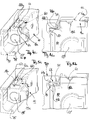
- FIG. 1 shows a carriage in an oblique view from an inward looking direction.
- the housing portion 10 to the right of an end portion on which an at least partially plate-shaped spring element is slidably mounted.
- the arm area with the main arm 30 as a stay arm and the control arm 35 are also visible, as a control section 40.
- the geometric axis is 20a for the bearing 12 and the associated roller 20 is in FIG. 8 seen.
- the roller 21 is spaced on the housing portion 10, and arranged on the other side of the main bearing 16 for the extension arm 30.
- This bearing 11 rotatably supports a shaft 21 'whose geometric axis is 21a and which roller 21 also in FIG. 8 shown from below.
- the housing portion 10 is above, closed above the rollers, so that they are covered from above and protected against incidental dirt.
- the rollers themselves have a large diameter, the FIG. 9 can be seen in a weg broken area in the roller 21.
- the roller occupies almost the entire height H10 of the housing section, reduced by the top covering wall 10a of the housing section.
- the rollers have a size of at least 90% of the height of the housing area.
- the overall height of the housing area is H 10 in FIG. 9 seen.
- a carriage is designed, which can move wings along.
- the wing can be moved via a tilted position into a parallel position, for which control arms not described here are arranged at the upper edge of the wing and are also displaceable.
- the wing can also be parked only in parallel, without an intermediate tilt position. In the parallel storage position, the wing is moved over the carriage.
- the wing is pivoted to the Abstellarm 30, for which the local recording serves as a bearing 100 with its geometric axis 100a.
- An arranged on the wing bolt engages in this recess as a bearing and couples the wing to the stay arm 30th
- the spaced carriages can both be designed the same, but can also be designed differently so far, as only one carriage uses a control section, and the other carriage has no such control section 40.
- the two spaced trolleys with their two rollers after FIG. 8 are otherwise the same education. They are coupled via a coupling rod Ks (or 19), which is inserted into a receptacle 19 ', such as FIG. 8 clarified.
- This coupling rod is attached to each carriage via a mounting screw 19b in a bore 19a.
- the bore has a geometric axis 19a 'which is perpendicular to the extension direction of the coupling rod, not shown in the figures.
- the coupling rod is preferably round and matched in their distance to the horizontal wing dimension so that the two carriages can support the wing and in the position S of the carriages are below the lower edge of the wing, but can protrude from it in the horizontal direction.
- the dimension below the wing is small, preferably less than 40 mm, in particular in the range of substantially 35 mm.
- the sash weight defines the necessary carrying capacity which the extension arm 30, or in the case of two carriages, can receive the extension arms 30 and can transfer to the housing 10. If wing due to requirements of the Thermal insulation getting fatter, they become heavier. If wings are getting higher due to optical conditions, they are also heavier. For thicker wings larger Ausstellweiten necessary so that the extension arm 30 is to be formed accordingly, while ensuring the inclusion of ever-increasing load capacity due to the geometric dimensions (height, thickness) of modern wings.
- rollers 20, 21 after FIG. 8 which are rotatably supported by their shafts 21 ', 20' in the lateral walls of the housing 10, support the carriage and run on a track, which is provided by a profiled carriage rail 70 mounted on the bottom of the frame.
- Such a track 75 is in FIGS. 4a, 5a seen.
- the carriage rail 70 is mounted in the region of the lower frame free-dimension on the frame.
- the dimension between the lower end of a wing flap, not shown, and the underside of the frame has the size of less than 40 mm described above.
- the rollers are designed in diameter large.
- the carriage with its housing portion 10 fits in this clearance, drivingly slidable on the track 75, and yet an upper cover of the rollers can be achieved through the top wall 10a of the housing.
- a handle control via a handle which controls the scissors held in slides above.
- These scissors can be positively controlled via the handle, or the handle itself serves to move the wing in a direction perpendicular to the plane of the window frame.
- the handle can also serve to move the wing in the parallel-parked position in the longitudinal direction, mobile supported on the rollers on the carriage rail 70 with the raceway 75 (also called running track).
- the position S (closed position) to FIG. 1 is after pivoting the stay arm 30 as a position O (open position) in FIG. 2 seen.
- the guide pin 39 which has an upper projection 39a and a lower projection 39b, has arrived at the opposite end (right) of the web guide (as a guide groove) 41 and is releasably engaged therein in an angled track portion 41b, to which the lower projection 39b serves as a preferred bolt ,
- This bolt 39b is capable of S of FIG. 1 located at the left end of the guide groove 41 of the control section 40.
- the control portion 40 has a groove 41 made of a straight portion 41a and one of which is angled to the left Snap-in section 41b.
- This latching section defines the position O of FIG. 2
- the end of the straight track portion 41a defines the layer S after FIG. 1 and 3 ,
- the control link 35 is how FIG. 2 or FIG. 8 make, angled or bent, so is not completely straight. It has a longer straight portion and an angled end portion thereof which carries the double projection 39 extending up and down in both directions.
- the latter projection 39 is arranged at the front end portion so as to form a circumferential collar in the thickness of the plate material of the control link 35 running on the control portion 40 and the top thereof while guiding the downwardly projecting projection 39b in the track 41b, 41a ,
- the link 35 is pivotally mounted at its other end via an axis 37 in a bearing of the stay arm 30.
- the bearing opening 38 and the axis 37 have the geometric axis 37a.
- the straight portion of the control link 35 is 35a, the portion bent or angled therebetween is 35b.
- the two positions O and S are from a different perspective, with the view from the outside on the outer flat side 30 'of the extension arm 30 in the Figures 6a and 6b shown.
- FIG. 6a is the angled end of the Ausstellarms 30 to see, which is not visible in the position O from the outside.
- the arm looks straightforward and elongated.
- the control link 35 is, however, angled, wherein the angled portion carries the guide pin 39, the upper projection 39a in FIG. 6b cooperates with a control block 50 having a top wall defining a closed surface 55 which faces up.
- the control block is mounted to the carriage rail at one end of the travel path of the carriage. It cooperates with the upwardly projecting projection 39 a, as will be explained in more detail below.
- Co-operation also finds from the collar of the curved portion 35b and a protruding nose 15 after Figure 2a, 2b in the locked position of the downwardly projecting projection 39b in the angled portion 41b of the guide groove 41 instead. This interaction will also be explained below.
- FIG. 6a which the other line of sight of the FIG. 3 is, it can be seen that the extension arm 30 from the visible side (from the outside) on the arm surface 30 'the control arm 35 completely hidden.
- the control arm 35 as in FIG. 8 it is not arranged above an upper side 30 "and not below an underside of the extension arm 30, rather its pivoting plane is designed so that it comes to rest between these two sides (upper side, lower side), ie the front side 30 '(view from FIG outside) reaches the cover of the control arm 35.
- the plate-shaped handlebar 35 is narrow in the height direction relative to the volume formed Ausstellarm 30.
- the volume design is also preferably suitable for that they can accommodate a gap or slot 31, as shown in the view of the FIG.
- This slot / gap 31 is provided for receiving the control arm 35 in the position S and also designed accordingly. Also, this slot 31 is located in the pivoting plane of the control arm 35, which is not shown separately, but by planar extension in the horizontal direction of the plate-shaped control arm is easy to imagine.
- control arm 35 Even if the control arm 35 is bulged slightly reinforced in a middle region, it remains flat plate-shaped.
- the stiffening bulge 35 c is received by the control arm 35 of the slot / gap 31. From the gap itself protrudes in the closed position of FIG. 3 The curved portion 35b protrudes a little way, and the longitudinal portion 35a of the control link 35 is almost completely received in the gap / slot 31 in the closed position S.
- the slit / gap 31 extends in the longitudinal direction of the extension arm and does not extend through the volume of training of Ausstellarms 30, but on the visible side 30 'as large a residual area of material remained to maintain the rigidity of the Ausstellarms 30.
- a plurality of cutting planes in the longitudinal direction is thereby obtained a U-shaped profile of the stay, with a relatively thick connecting leg and two webs, one of which FIG. 2 stronger and the other narrower.
- the gap or slot is therefore not in the middle between the top and bottom of the stay, but slightly offset upwards.
- the slot or gap 31 can thus at least partially record the control link 35 in the closed position, and let him swing out for the position O. At least in sections, the control link is in the situation S recorded, wherein the straight portion is almost completely absorbed, and the curved portion 35b protrudes to allow the guide the control section 40 in the position S from the extension arm 30.
- At least in sections could also be understood that it is no more than sections, in order to obtain the control functions by the double projection 39, in particular as a double pin, in the guide groove 41 of the control section 40.
- the extension arm which is made thicker in terms of volume, relative to the control arm 35, is formed substantially rectilinearly stretched, at least in the region of the housing 10 in the position O after FIG. 2 protrudes.
- the geometry of the arms is also in FIG. 8 seen in the view from below.
- the remaining piece 34 after FIG. 6a which is visible in the position S from the outside, is bent, but is capable of O after FIG. 6b barely visible from the visible side (from the outside).
- this bent portion at the bearing 36/16, ie at the bearing end of the stay arm 30 this is to be named as elongated straight. Its volumetric training has already been explained in connection with the gap / slot 31.
- the control takes place via a double projection 39, which has an upwardly projecting projection 39a and a downwardly projecting projection 39b.
- These two are preferably designed as a bolt, more preferably provided with a rotatable sleeve in order to be easier to guide and to produce less friction in the guide.
- the double projection which from all views of Figures 2 , of the FIG. 6b and the detail enlargements of the FIGS. 11 and 12 can be seen, has two different functions or tasks above and below, with essentially the same design.
- Arranged is the double projection in the bent (curved) end portion 35b of the control arm 35. It leaves a covenant around it as a plate-shaped collar stand, so does not quite extend to the outer edge of the control arm 35 in the region 35b zoom.
- the downwardly projecting projection 39b is provided for guiding from below.
- the triggering from the locked position after FIG. 2 is the task and function of the upwardly projecting projection 39b.
- the locked position is that for the parallel adjustment of the wing.
- the triggering takes place from above.
- the triggering takes place as it is in FIG. 6b is achieved by running the upwardly projecting projection 39b in a lateral recess 51 of the control block 50.
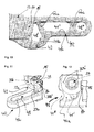
- This control block 50 is in FIGS. 7a, 7b explained from two oblique views.
- the shrinkage of the upwardly projecting projection 39 a in the direction V 39 is shown, in the a bevel 51, of which the control block 50 may have two to be used for left-hinging and right-hinged applications can.
- the control block 50 is mounted on the carriage rail 70.
- the carriage with the housing 10 runs in FIG. 6b - When opening the arm 30 - from left to right, and he engages at the end of the travel with the leading (forward projecting) control section 40 in a transverse through further recess 53 of the control block 50.
- the control by the inclined path 51 at also obliquely placed groove portion 41b of the guide groove 41 leads to a retrieval of the control arm 35, respectively of the downwardly projecting projection 39b from the angled groove portion 41b and leaving the position O, as in FIG. 6b shown.
- control section 40 is designed to lead forward. He is designed nose-shaped slim, the control section 40 is nevertheless stiffened, which is based on the FIGS. 10 to 12 is explained in more detail.
- the guide groove 41 with its two sections 41a, 41b is provided in the nose-shaped slender control section 40.
- the angled section 41b is in a bulging bulged side region 42 (belly) to FIG. 10 placed, which in turn engages in a bay-shaped recess 33 in the position S of the stay arm 30.
- the bay-shaped recess 33 is disposed below the slot / gap 31, and should take out as little material as possible from the volume formed Ausstellarm 30 in order to maintain its rigidity, but at the same time the closed position position S as close as possible to the Casing section 10 and the carriage rail 70 to allow. It is obvious FIG. 2 also that this bay-shaped recess 33 does not reach right up to the underside of the extension arm in the height direction, but the extension arm 30 is closed surface-wise on three sides.
- the guide groove 41 is not completely closed down, but has a not more than partially closed formed bottom structure. In other words, the soil is present in sections, resulting from the FIGS. 10 and 12 and FIG. 8 becomes apparent.
- FIG. 10 is seen from above into the groove 41 whose web shape; the section 41a is the rectilinear section and the angled section 41b extends downward at an angle of slightly less than 90 °. It thus forms a pocket-shaped recess for the latched position S of the downwardly facing projection 39b.
- FIGS. 2a, 2b An overarching section 15, as in FIGS. 2a, 2b can be seen in the detail enlargements engages over the collar 35b ', which surrounds the double projection 39, and a part of the bent portion 35b of the control arm 35 is.
- This attack by the nose-shaped projection 15 ensures a vertical moving out or jumping out of the projection 39b from the guide groove 41 and a vertical displacement of the control link 35th
- the mentioned spring as a spring element 14 is clearer in FIG. 2b in the supervision and in FIG. 2a to see. It has a bow portion, which is visible in sections next to the nose 15, but is located substantially portion below the nose-shaped cross-section 15.
- the spring element 14 is continued in a holding portion 14b, 14c, which is U-shaped and through the above-open window of the holding chamber 13 in FIG. 2b is apparent.
- the spring is inserted from below into an opening, and engages with its free end 14c behind a projection in the holding chamber 13 a. It is thereby fixed in position, but can be replaced at the same time, when with a tool, the free end 14c is bent away from the projection, and the spring element 14 is taken down. A new, identical spring element 14 can then be inserted and fixed from below.
- the securing position in the locked position according to FIG. 2 or FIG. 8 , or the FIGS. 11 and 12 is additionally secured by the spring element 14. This exerts a pressing force on the side plate projection 35b 'as a collar of the lifted portion of the control arm 35, and presses it reliably in the locked position at the end of the angled portion 41b of the guide groove 41st
- a portion of the arcuately shaped spring back of the retaining spring 14 is disposed below the nose 15, and above an upper surface of the control section 40th
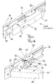
- the pivoting of a carriage in the carriage rail is based on the FIGS. 4a to 5b be explained.
- the end portion of the carriage shown here is the one in the Figures 1 and 2 is located on the right. It is an end portion, into which the connecting rod 19 is inserted, which is fastened via a - not shown - threaded hole 19a with a mounting screw.
- a spring piece 60 is provided, which has two locking positions, which are described below.
- the spring 60 is also in FIG. 1 to see and there has the location, which in FIG. 4a in the oblique view and in FIG. 4b can be seen in the front view. It is a locked position, which is achieved by a first groove 18a, which is arranged on top of the carriage end (the housing of the carriage).
- a second groove is designated to the left of it with 18b and has a distance. There are thus two spaced groove sections, as on the FIG. 4a seen.
- the spring piece 60 is arranged on top and has a shape of several sections.
- a resilient portion 62 has a U- or V-shape and a grasping portion 63 at the end. This one is in FIG. 5b most clearly seen, engaged in the second detent position in the groove portion 18b.
- the spring piece 60 further has a projecting planar portion 61, which in the example shown is achieved by a deflection 61a with feedback with additional stiffening waveforms 61b.
- This "front portion” may also be a simple plate-shaped piece of a sufficiently stable material, which is provided at the right end with a spring portion which corresponds to that portion 62, 63 which in FIG. 4a is freely visible.
- this spring piece 60 is first that it is displaceable.
- the spring piece 60 is moved in the direction F 60 , as in FIG. 5a is shown. It then reaches the second detent position in the grooves 18b.
- the section 61 protrudes far and blocks a gap 71a, which was previously free. This free gap is needed for swinging in and swinging out the carriage.
- the gap 71a interferes with reliable movement and could cause the carriage to pop out of its path 75. This can be prevented by the pushing of the spring piece 60 in the horizontal direction when the spring occupies the second detent position in the grooves 18b, and the front portion 61 reduces the gap opening.
- the plate-like front portion 61 of the spring piece 60 can prevent the carriage from disengaging from the carriage rail.
- the spring piece 60 designed as a whole out of spring plate FIGS. 4a to 5b may also have only one spring portion in the region 62, and the front (plate-like) portion 61- in a manner not shown - plate-shaped or may be formed as a plate, the plate thickness is suitable to choose to reduce the gap 71a in its height ,
- the at least one, preferably two pairs of grooves 18a, 18b serve the detent position (s) of the spring piece, and rewrite its position in a position permitting swiveling FIG. 4b , and a position preventing the falling out or swinging out after FIG. 5b ,
- the mutatis mutandis plate-shaped portion 61 of the spring piece secures in the gap 71 a.
- the gap 71a is thereby substantially reduced.
- the extent of the reductions is an almost complete closing of the gap, such as FIG. 5b shows.
- one of the locking positions 18a, 18b may also be omitted or may be a held by friction or clamping position of the spring piece.
- This latching position is preferably that of the groove pair 18a.
- the spring can only be placed without being locked separately on the edge in a recess, cf. FIG. 5a , Only pushing in F 60 of the spring piece 60 and the locking in the groove pair 18 b is useful for the reliability of the blocking of the gap 71 a.
- the extension arm can be seen here from the visible side from the outside. He has a height H 30 . This height brings the Ausstellarm 30 high rigidity and load capacity.
- the height H 30 is almost the height H 10 , which relates to the housing portion 10 of the carriage.
- the height H 30 is greater than at least 80%, preferably greater than 90% of the height H 10 .
- the size of the diameter of the roller 21 which also has almost the size H 10 , while above 90% to above 95% of the height H 10 .
- the height H 30 of the extension arm 30 is substantially thicker and thereby measured at least four times as strong in the height direction.
- the height extent of the control arm 35 is still to be regarded as a plate-shaped even with stiffening expression 35c.
- FIG. 9 Also visible FIG. 9 is that above the top and bottom of the Ausstellarms 30 no control arm is visible or arranged, and that the overall height of the Ausstellarms 30 can contribute to the overall load capacity and rigidity of this arm, especially if the provided gap 31 in a Example does not extend completely through the transverse direction of the extension arm 30, and also extends only slightly in the longitudinal direction, and thus does not bring about a reduction in the load capacity and the rigidity of the Ausstellarms 30.
- the gap 71a is dimensioned below the projecting portion 71 of the carriage rail 70 so that this projection 17 can be swung in below 71, and thereafter the protection against jumping out when the gap is reduced.
- the projection 17 would be at the emergence of the carriage on an obstacle against the down projecting projection 71, and with inserted spring piece 60 takes over this striking the plate-shaped portion 61, which lies on the projection 17.
- the section 61 is for this purpose made of said, sufficiently stable material.
- the longitudinal extension of the projection 17 may, as FIG. 2 shows to be limited.
- the spring piece 60 projects with its plate-like portion at both ends of the projection 17 beyond this in the longitudinal direction.
- the projection 17 supports the plate-like configuration 61 of the spring piece 60 resting thereon, in order to prevent the spring piece 60 from being pushed out by operational movement.
- the effective plate-shaped portion 61 may protrude inwardly over the front end of the projection, as in FIG. 5b is shown.
- the spring piece shown there with its plate-like portion 61 protrudes front side (seen to the left) on the securing projection 17 also.
Landscapes
- Engineering & Computer Science (AREA)
- Mechanical Engineering (AREA)
- Closing And Opening Devices For Wings, And Checks For Wings (AREA)
- Toys (AREA)
- Bearings For Parts Moving Linearly (AREA)
- Power-Operated Mechanisms For Wings (AREA)
- Support Devices For Sliding Doors (AREA)
- Carriages For Children, Sleds, And Other Hand-Operated Vehicles (AREA)
Priority Applications (5)
| Application Number | Priority Date | Filing Date | Title |
|---|---|---|---|
| PL12175677T PL2538009T3 (pl) | 2009-01-11 | 2009-10-15 | Kompaktowy wózek jezdny do skrzydła z odstawioną równolegle, zabezpieczoną pozycją |
| EP12175677.9A EP2538009B1 (fr) | 2009-01-11 | 2009-10-15 | Chariot compact pour un battant ayant une position de déplacement parallèle sécurisée |
| SI200931720T SI2538009T1 (sl) | 2009-01-11 | 2009-10-15 | Kompakten voziček za krilo z vzporedno odmaknjenim, zavarovanim položajem |
| EP17169549.7A EP3216959B1 (fr) | 2009-01-11 | 2009-10-15 | Chariot pour un battant destiné au déplacement longitudinal du battant dans une position parallèle |
| HRP20171399TT HRP20171399T1 (hr) | 2009-01-11 | 2017-09-15 | Kompaktne sanjke za prozorsko krilo s paralelnim odmakom i osiguranim položajem |
Applications Claiming Priority (3)
| Application Number | Priority Date | Filing Date | Title |
|---|---|---|---|
| EP09150358 | 2009-01-11 | ||
| EP12175677.9A EP2538009B1 (fr) | 2009-01-11 | 2009-10-15 | Chariot compact pour un battant ayant une position de déplacement parallèle sécurisée |
| EP09173096A EP2216472B1 (fr) | 2009-01-11 | 2009-10-15 | Chariot compact pour un battant et procédé destiné au déplacement en longueur du battant dans une position de rangement parallèle |
Related Parent Applications (2)
| Application Number | Title | Priority Date | Filing Date |
|---|---|---|---|
| EP09173096.0 Division | 2009-10-15 | ||
| EP09173096A Division EP2216472B1 (fr) | 2009-01-11 | 2009-10-15 | Chariot compact pour un battant et procédé destiné au déplacement en longueur du battant dans une position de rangement parallèle |
Related Child Applications (2)
| Application Number | Title | Priority Date | Filing Date |
|---|---|---|---|
| EP17169549.7A Division EP3216959B1 (fr) | 2009-01-11 | 2009-10-15 | Chariot pour un battant destiné au déplacement longitudinal du battant dans une position parallèle |
| EP17169549.7A Division-Into EP3216959B1 (fr) | 2009-01-11 | 2009-10-15 | Chariot pour un battant destiné au déplacement longitudinal du battant dans une position parallèle |
Publications (3)
| Publication Number | Publication Date |
|---|---|
| EP2538009A2 true EP2538009A2 (fr) | 2012-12-26 |
| EP2538009A3 EP2538009A3 (fr) | 2016-04-20 |
| EP2538009B1 EP2538009B1 (fr) | 2017-06-28 |
Family
ID=42115346
Family Applications (3)
| Application Number | Title | Priority Date | Filing Date |
|---|---|---|---|
| EP09173096A Active EP2216472B1 (fr) | 2009-01-11 | 2009-10-15 | Chariot compact pour un battant et procédé destiné au déplacement en longueur du battant dans une position de rangement parallèle |
| EP17169549.7A Active EP3216959B1 (fr) | 2009-01-11 | 2009-10-15 | Chariot pour un battant destiné au déplacement longitudinal du battant dans une position parallèle |
| EP12175677.9A Active EP2538009B1 (fr) | 2009-01-11 | 2009-10-15 | Chariot compact pour un battant ayant une position de déplacement parallèle sécurisée |
Family Applications Before (2)
| Application Number | Title | Priority Date | Filing Date |
|---|---|---|---|
| EP09173096A Active EP2216472B1 (fr) | 2009-01-11 | 2009-10-15 | Chariot compact pour un battant et procédé destiné au déplacement en longueur du battant dans une position de rangement parallèle |
| EP17169549.7A Active EP3216959B1 (fr) | 2009-01-11 | 2009-10-15 | Chariot pour un battant destiné au déplacement longitudinal du battant dans une position parallèle |
Country Status (10)
| Country | Link |
|---|---|
| EP (3) | EP2216472B1 (fr) |
| DE (1) | DE202009019144U1 (fr) |
| DK (2) | DK2216472T3 (fr) |
| ES (1) | ES2641947T3 (fr) |
| HR (1) | HRP20171399T1 (fr) |
| HU (1) | HUE035800T2 (fr) |
| LT (1) | LT2538009T (fr) |
| PL (3) | PL3216959T3 (fr) |
| PT (1) | PT2538009T (fr) |
| SI (1) | SI2538009T1 (fr) |
Cited By (2)
| Publication number | Priority date | Publication date | Assignee | Title |
|---|---|---|---|---|
| DE202016001162U1 (de) | 2016-02-22 | 2016-03-02 | Siegenia-Aubi Kg | Aushebeschutzeinrichtung für einen parallel verschiebbaren Flügel als Schiebekippflügel oder Schiebeflügel |
| DE102017003073A1 (de) | 2017-03-30 | 2018-10-04 | Roto Frank Ag | Wippenförmige Aushebesicherung |
Families Citing this family (2)
| Publication number | Priority date | Publication date | Assignee | Title |
|---|---|---|---|---|
| DE102017115823A1 (de) | 2017-07-13 | 2019-01-17 | Hautau Gmbh | Beschlag für einen kipp- und schiebbaren Flügel und Verfahren zum Öffnen und Schließen eines parallel abstellbaren und verschiebbaren Flügels |
| DE102017214268B4 (de) | 2017-08-16 | 2020-07-09 | Roto Frank Ag | Laufwagen mit einer starren Aushebesicherung |
Citations (5)
| Publication number | Priority date | Publication date | Assignee | Title |
|---|---|---|---|---|
| DE3234677A1 (de) | 1982-09-18 | 1984-03-22 | Gretsch-Unitas GmbH Baubeschläge, 7257 Ditzingen | Beschlag fuer einen zumindest parallelabstellbaren fluegel eines fensters, einer tuer od. dgl. |
| EP0201717B1 (fr) | 1985-05-08 | 1988-08-24 | Gretsch Unitas GmbH Baubeschläge | Ferrure pour un battant de fenêtre, porte ou similaire qui peut au moins être déplacé dans un plan parallèle |
| EP0619410B1 (fr) | 1993-04-06 | 1997-03-12 | W. HAUTAU GmbH | Ferrure pour battant coulissant avec goujon de guidage non circulaire |
| EP1388631A2 (fr) | 2002-08-08 | 2004-02-11 | Hettich-Heinze GmbH & Co. KG | Support de galet pour porte coulissante |
| EP1959080A2 (fr) | 2007-02-15 | 2008-08-20 | HAUTAU GmbH | Butée de battant mobile de fenêtre ou de porte |
Family Cites Families (15)
| Publication number | Priority date | Publication date | Assignee | Title |
|---|---|---|---|---|
| DE567048C (de) | 1932-12-27 | Wilhelm Hautau | Rolle fuer Schiebetuergehaenge | |
| DE8435367U1 (de) | 1984-12-03 | 1985-04-11 | W. Hautau GmbH Baubeschlagfabrik, 3068 Helpsen | Sperreinrichtung zum Sperren eines Ausstellarmes für parallel abstellbare Schiebeflügel von Fenstern, Türen oder dgl. |
| DE8515998U1 (de) * | 1985-05-31 | 1985-07-18 | W. Hautau GmbH, 3068 Helpsen | Beschlag für einen mittels Ausstellarm parallel abstellbaren Schiebeflügel für Fenster, Türen oder dgl. |
| DE8707044U1 (fr) * | 1987-05-15 | 1987-07-09 | W. Hautau Gmbh, 3068 Helpsen, De | |
| DE29516438U1 (de) | 1994-10-19 | 1996-03-07 | Linder Gmbh A | Schiebetürbeschlag |
| DK32698A (da) * | 1997-11-11 | 1999-05-12 | Velux Ind As | Vindues- eller dørarrangement omfattende et skydevindue eller en skydedør |
| DE19837193A1 (de) * | 1998-08-17 | 2000-03-02 | Weidtmann Wilhelm Kg | Abstell-Schiebebeschlag für Fenster, Türen o. dgl. |
| GB2356588B (en) | 1999-11-25 | 2003-11-12 | Rolls Royce Plc | Processing tip treatment bars in a gas turbine engine |
| IT249753Y1 (it) * | 2000-01-28 | 2003-05-28 | Ferrari Franco | Un sistema di sostegno e scorrimento per una porta di un mobile |
| ATE294312T1 (de) * | 2000-07-04 | 2005-05-15 | Gretsch Unitas Gmbh | Laufwagen für einen parallelschiebe- und kippbeschlag eines gebäudefensters oder einer gebäudefenstertür sowie gebäudefenster bzw. gebäudefenstertür mit einem solchen parallelschiebe-kippbeschlag |
| DE202004019098U1 (de) | 2004-12-10 | 2006-04-13 | Weber & Co. Gmbh Kg | Laufrollenteil für einen Schiebetürbeschlag |
| DE202005007687U1 (de) | 2005-05-17 | 2006-09-28 | Weber & Co. Gmbh Kg | Laufrollenteil für einen Schiebetürbeschlag |
| DE102007022311B4 (de) | 2006-12-16 | 2016-03-10 | Hautau Gmbh | Höhenverstellbare Lagereinheit für einen Schiebeflügel |
| DE202008004933U1 (de) * | 2008-04-01 | 2008-06-19 | Gretsch-Unitas GmbH Baubeschläge | Beschlag für einen zumindest kippbaren und/oder parallelabstellbaren Flügel eines Fensters, einer Tür o.dgl. |
| DE102012202986B4 (de) | 2012-02-28 | 2019-10-24 | Roto Frank Ag | Beschlag für eine Schiebetür oder ein Schiebefenster |
-
2009
- 2009-10-15 EP EP09173096A patent/EP2216472B1/fr active Active
- 2009-10-15 HU HUE12175677A patent/HUE035800T2/en unknown
- 2009-10-15 PL PL17169549.7T patent/PL3216959T3/pl unknown
- 2009-10-15 PT PT121756779T patent/PT2538009T/pt unknown
- 2009-10-15 EP EP17169549.7A patent/EP3216959B1/fr active Active
- 2009-10-15 DE DE202009019144.3U patent/DE202009019144U1/de not_active Expired - Lifetime
- 2009-10-15 PL PL09173096T patent/PL2216472T3/pl unknown
- 2009-10-15 PL PL12175677T patent/PL2538009T3/pl unknown
- 2009-10-15 SI SI200931720T patent/SI2538009T1/sl unknown
- 2009-10-15 EP EP12175677.9A patent/EP2538009B1/fr active Active
- 2009-10-15 DK DK09173096.0T patent/DK2216472T3/da active
- 2009-10-15 DK DK12175677.9T patent/DK2538009T3/en active
- 2009-10-15 ES ES12175677.9T patent/ES2641947T3/es active Active
- 2009-10-15 LT LTEP12175677.9T patent/LT2538009T/lt unknown
-
2017
- 2017-09-15 HR HRP20171399TT patent/HRP20171399T1/hr unknown
Patent Citations (6)
| Publication number | Priority date | Publication date | Assignee | Title |
|---|---|---|---|---|
| DE3234677A1 (de) | 1982-09-18 | 1984-03-22 | Gretsch-Unitas GmbH Baubeschläge, 7257 Ditzingen | Beschlag fuer einen zumindest parallelabstellbaren fluegel eines fensters, einer tuer od. dgl. |
| EP0103725B1 (fr) | 1982-09-18 | 1988-12-07 | Gretsch-Unitas GmbH Baubeschläge | Ferrure pour un battant de fenêtre, porte ou similaire, qui peut au moins être déplacée dans un plan parallèle |
| EP0201717B1 (fr) | 1985-05-08 | 1988-08-24 | Gretsch Unitas GmbH Baubeschläge | Ferrure pour un battant de fenêtre, porte ou similaire qui peut au moins être déplacé dans un plan parallèle |
| EP0619410B1 (fr) | 1993-04-06 | 1997-03-12 | W. HAUTAU GmbH | Ferrure pour battant coulissant avec goujon de guidage non circulaire |
| EP1388631A2 (fr) | 2002-08-08 | 2004-02-11 | Hettich-Heinze GmbH & Co. KG | Support de galet pour porte coulissante |
| EP1959080A2 (fr) | 2007-02-15 | 2008-08-20 | HAUTAU GmbH | Butée de battant mobile de fenêtre ou de porte |
Cited By (3)
| Publication number | Priority date | Publication date | Assignee | Title |
|---|---|---|---|---|
| DE202016001162U1 (de) | 2016-02-22 | 2016-03-02 | Siegenia-Aubi Kg | Aushebeschutzeinrichtung für einen parallel verschiebbaren Flügel als Schiebekippflügel oder Schiebeflügel |
| WO2017144193A1 (fr) | 2016-02-22 | 2017-08-31 | Siegenia-Aubi Kg | Dispositif anti-relèvement pour un battant à coulissement parallèle se présentant sous forme d'oscillo-battant coulissant ou de battant coulissant |
| DE102017003073A1 (de) | 2017-03-30 | 2018-10-04 | Roto Frank Ag | Wippenförmige Aushebesicherung |
Also Published As
| Publication number | Publication date |
|---|---|
| PL3216959T3 (pl) | 2022-11-21 |
| DK2216472T3 (da) | 2012-10-22 |
| LT2538009T (lt) | 2017-08-25 |
| EP3216959B1 (fr) | 2022-08-10 |
| PL2538009T3 (pl) | 2017-12-29 |
| DK2538009T3 (en) | 2017-10-09 |
| PT2538009T (pt) | 2017-09-18 |
| ES2641947T3 (es) | 2017-11-14 |
| DE202009019144U1 (de) | 2017-02-03 |
| HRP20171399T1 (hr) | 2017-11-03 |
| EP2216472A2 (fr) | 2010-08-11 |
| SI2538009T1 (sl) | 2017-10-30 |
| EP2216472B1 (fr) | 2012-07-11 |
| EP3216959A1 (fr) | 2017-09-13 |
| HUE035800T2 (en) | 2018-05-28 |
| EP2216472A3 (fr) | 2011-07-06 |
| EP2538009B1 (fr) | 2017-06-28 |
| PL2216472T3 (pl) | 2012-11-30 |
| EP2538009A3 (fr) | 2016-04-20 |
Similar Documents
| Publication | Publication Date | Title |
|---|---|---|
| EP2384386B1 (fr) | Chariot compact pour battant de poids élevé pouvant effectuer un déplacement longitudinal | |
| EP0356728B1 (fr) | Dispositif de commande de la séquence de fermeture de portes à doubles battants | |
| DE10014760B4 (de) | Heckscheibenrollo mit gefederten Rollen | |
| EP3263819B1 (fr) | Porte mobile verticalement comprenant un vantail de porte | |
| EP2041385B1 (fr) | Dispositif pour portes coulissantes ou portails coulissants | |
| EP3545158B1 (fr) | Porte roulante | |
| WO2020097639A1 (fr) | Système de guidage pour le guidage d'un battant de porte monté de manière mobile | |
| EP2538009B1 (fr) | Chariot compact pour un battant ayant une position de déplacement parallèle sécurisée | |
| EP2799651A1 (fr) | Ferrure de porte coulissante pour meuble | |
| DE102009004013B4 (de) | Kompakter Laufwagen für einen Flügel zum Längs-Bewegen des Flügels in einer parallel-abgestellten Lage | |
| DE102009061095B3 (de) | Laufwagen für einen Flügel zum Längs-Bewegen des Flügels in einer parallel abgestellten Lage | |
| DE102012202981B4 (de) | Beschlag für einen parallel abstellbaren und in dieser Lage verschiebbaren Flügel eines Fensters, einer Tür oder dergleichen | |
| EP2391790A1 (fr) | Ensemble ferrure pour coupole lumineuse | |
| EP1798361B1 (fr) | Porte | |
| EP1630336B1 (fr) | Porte avec un dispositif permettant d'améliorer la manière d'ouverture de la porte, en particulier d'une porte sectionnelle basculante | |
| DE19825071C2 (de) | Parallelausstellfenster mit Drehfunktion | |
| DE2754962A1 (de) | Kippfenster, insbesondere oberlichtfenster | |
| AT510094A1 (de) | Beschlaganordnung | |
| DE102017202727B4 (de) | Verdeckt angeordneter Beschlag für Fenster, Türen oder dergleichen | |
| DE202006019139U1 (de) | Beschlaggarnitur für Paniktürverschlüsse | |
| CH622854A5 (en) | Setting-out device on wings or the like of windows or doors | |
| EP4083359A1 (fr) | Dispositif coulissant pour une porte coulissante et meuble | |
| DE19545673C1 (de) | Speisentransportwagen | |
| EP2813654B1 (fr) | Système de verrouillage, dispositif de verrouillage et procédé de fermeture sélective d'une ouverture | |
| DE19807260C2 (de) | Langgestreckte Fangeinrichtung mit begrenzt beweglichem Bremsmantelstück |
Legal Events
| Date | Code | Title | Description |
|---|---|---|---|
| PUAI | Public reference made under article 153(3) epc to a published international application that has entered the european phase |
Free format text: ORIGINAL CODE: 0009012 |
|
| AC | Divisional application: reference to earlier application |
Ref document number: 2216472 Country of ref document: EP Kind code of ref document: P |
|
| AK | Designated contracting states |
Kind code of ref document: A2 Designated state(s): AT BE BG CH CY CZ DE DK EE ES FI FR GB GR HR HU IE IS IT LI LT LU LV MC MK MT NL NO PL PT RO SE SI SK SM TR |
|
| TPAC | Observations filed by third parties |
Free format text: ORIGINAL CODE: EPIDOSNTIPA |
|
| RIC1 | Information provided on ipc code assigned before grant |
Ipc: E05D 15/10 20060101AFI20160112BHEP |
|
| PUAL | Search report despatched |
Free format text: ORIGINAL CODE: 0009013 |
|
| AK | Designated contracting states |
Kind code of ref document: A3 Designated state(s): AT BE BG CH CY CZ DE DK EE ES FI FR GB GR HR HU IE IS IT LI LT LU LV MC MK MT NL NO PL PT RO SE SI SK SM TR |
|
| RIC1 | Information provided on ipc code assigned before grant |
Ipc: E05D 15/10 20060101AFI20160315BHEP |
|
| TPAC | Observations filed by third parties |
Free format text: ORIGINAL CODE: EPIDOSNTIPA |
|
| 17P | Request for examination filed |
Effective date: 20161020 |
|
| TPAC | Observations filed by third parties |
Free format text: ORIGINAL CODE: EPIDOSNTIPA |
|
| TPAC | Observations filed by third parties |
Free format text: ORIGINAL CODE: EPIDOSNTIPA |
|
| STAA | Information on the status of an ep patent application or granted ep patent |
Free format text: STATUS: EXAMINATION IS IN PROGRESS |
|
| TPAC | Observations filed by third parties |
Free format text: ORIGINAL CODE: EPIDOSNTIPA |
|
| 17Q | First examination report despatched |
Effective date: 20170209 |
|
| TPAC | Observations filed by third parties |
Free format text: ORIGINAL CODE: EPIDOSNTIPA |
|
| GRAP | Despatch of communication of intention to grant a patent |
Free format text: ORIGINAL CODE: EPIDOSNIGR1 |
|
| STAA | Information on the status of an ep patent application or granted ep patent |
Free format text: STATUS: GRANT OF PATENT IS INTENDED |
|
| GRAS | Grant fee paid |
Free format text: ORIGINAL CODE: EPIDOSNIGR3 |
|
| INTG | Intention to grant announced |
Effective date: 20170404 |
|
| GRAA | (expected) grant |
Free format text: ORIGINAL CODE: 0009210 |
|
| STAA | Information on the status of an ep patent application or granted ep patent |
Free format text: STATUS: THE PATENT HAS BEEN GRANTED |
|
| RAP1 | Party data changed (applicant data changed or rights of an application transferred) |
Owner name: HAUTAU GMBH |
|
| AC | Divisional application: reference to earlier application |
Ref document number: 2216472 Country of ref document: EP Kind code of ref document: P |
|
| AK | Designated contracting states |
Kind code of ref document: B1 Designated state(s): AT BE BG CH CY CZ DE DK EE ES FI FR GB GR HR HU IE IS IT LI LT LU LV MC MK MT NL NO PL PT RO SE SI SK SM TR |
|
| REG | Reference to a national code |
Ref country code: GB Ref legal event code: FG4D Free format text: NOT ENGLISH |
|
| REG | Reference to a national code |
Ref country code: CH Ref legal event code: EP |
|
| REG | Reference to a national code |
Ref country code: AT Ref legal event code: REF Ref document number: 904990 Country of ref document: AT Kind code of ref document: T Effective date: 20170715 |
|
| REG | Reference to a national code |
Ref country code: IE Ref legal event code: FG4D Free format text: LANGUAGE OF EP DOCUMENT: GERMAN |
|
| REG | Reference to a national code |
Ref country code: DE Ref legal event code: R096 Ref document number: 502009014116 Country of ref document: DE |
|
| REG | Reference to a national code |
Ref country code: CH Ref legal event code: NV Representative=s name: ISLER AND PEDRAZZINI AG, CH |
|
| REG | Reference to a national code |
Ref country code: HR Ref legal event code: TUEP Ref document number: P20171399 Country of ref document: HR |
|
| REG | Reference to a national code |
Ref country code: PT Ref legal event code: SC4A Ref document number: 2538009 Country of ref document: PT Date of ref document: 20170918 Kind code of ref document: T Free format text: AVAILABILITY OF NATIONAL TRANSLATION Effective date: 20170912 |
|
| REG | Reference to a national code |
Ref country code: SE Ref legal event code: TRGR Ref country code: RO Ref legal event code: EPE |
|
| REG | Reference to a national code |
Ref country code: NL Ref legal event code: FP |
|
| REG | Reference to a national code |
Ref country code: HR Ref legal event code: ODRP Ref document number: P20171399 Country of ref document: HR Payment date: 20171003 Year of fee payment: 9 |
|
| REG | Reference to a national code |
Ref country code: DE Ref legal event code: R026 Ref document number: 502009014116 Country of ref document: DE |
|
| PLBI | Opposition filed |
Free format text: ORIGINAL CODE: 0009260 |
|
| REG | Reference to a national code |
Ref country code: DK Ref legal event code: T3 Effective date: 20171003 |
|
| REG | Reference to a national code |
Ref country code: EE Ref legal event code: FG4A Ref document number: E014197 Country of ref document: EE Effective date: 20170814 |
|
| REG | Reference to a national code |
Ref country code: FR Ref legal event code: PLFP Year of fee payment: 9 |
|
| PG25 | Lapsed in a contracting state [announced via postgrant information from national office to epo] |
Ref country code: FI Free format text: LAPSE BECAUSE OF FAILURE TO SUBMIT A TRANSLATION OF THE DESCRIPTION OR TO PAY THE FEE WITHIN THE PRESCRIBED TIME-LIMIT Effective date: 20170628 |
|
| REG | Reference to a national code |
Ref country code: HR Ref legal event code: T1PR Ref document number: P20171399 Country of ref document: HR |
|
| 26 | Opposition filed |
Opponent name: ROTO FRANK AG Effective date: 20171005 |
|
| REG | Reference to a national code |
Ref country code: ES Ref legal event code: FG2A Ref document number: 2641947 Country of ref document: ES Kind code of ref document: T3 Effective date: 20171114 |
|
| PGFP | Annual fee paid to national office [announced via postgrant information from national office to epo] |
Ref country code: LU Payment date: 20171023 Year of fee payment: 9 |
|
| REG | Reference to a national code |
Ref country code: NO Ref legal event code: T2 Effective date: 20170628 |
|
| REG | Reference to a national code |
Ref country code: SK Ref legal event code: T3 Ref document number: E 25134 Country of ref document: SK |
|
| PGFP | Annual fee paid to national office [announced via postgrant information from national office to epo] |
Ref country code: CZ Payment date: 20171003 Year of fee payment: 9 Ref country code: EE Payment date: 20171019 Year of fee payment: 9 Ref country code: LT Payment date: 20171003 Year of fee payment: 9 Ref country code: NO Payment date: 20171020 Year of fee payment: 9 Ref country code: DK Payment date: 20171024 Year of fee payment: 9 Ref country code: FR Payment date: 20171023 Year of fee payment: 9 Ref country code: RO Payment date: 20171004 Year of fee payment: 9 Ref country code: SK Payment date: 20171004 Year of fee payment: 9 |
|
| PG25 | Lapsed in a contracting state [announced via postgrant information from national office to epo] |
Ref country code: IS Free format text: LAPSE BECAUSE OF FAILURE TO SUBMIT A TRANSLATION OF THE DESCRIPTION OR TO PAY THE FEE WITHIN THE PRESCRIBED TIME-LIMIT Effective date: 20171028 Ref country code: SM Free format text: LAPSE BECAUSE OF FAILURE TO SUBMIT A TRANSLATION OF THE DESCRIPTION OR TO PAY THE FEE WITHIN THE PRESCRIBED TIME-LIMIT Effective date: 20170628 |
|
| PGFP | Annual fee paid to national office [announced via postgrant information from national office to epo] |
Ref country code: LV Payment date: 20171024 Year of fee payment: 9 Ref country code: PT Payment date: 20171003 Year of fee payment: 9 Ref country code: AT Payment date: 20171018 Year of fee payment: 9 Ref country code: SE Payment date: 20171024 Year of fee payment: 9 Ref country code: ES Payment date: 20171103 Year of fee payment: 9 Ref country code: BE Payment date: 20171023 Year of fee payment: 9 Ref country code: IE Payment date: 20171020 Year of fee payment: 9 Ref country code: CH Payment date: 20171023 Year of fee payment: 9 Ref country code: HR Payment date: 20171003 Year of fee payment: 9 Ref country code: BG Payment date: 20171025 Year of fee payment: 9 Ref country code: NL Payment date: 20171023 Year of fee payment: 9 Ref country code: GB Payment date: 20171024 Year of fee payment: 9 Ref country code: SI Payment date: 20171002 Year of fee payment: 9 Ref country code: GR Payment date: 20171026 Year of fee payment: 9 |
|
| REG | Reference to a national code |
Ref country code: GR Ref legal event code: EP Ref document number: 20170402598 Country of ref document: GR Effective date: 20180309 |
|
| PLAX | Notice of opposition and request to file observation + time limit sent |
Free format text: ORIGINAL CODE: EPIDOSNOBS2 |
|
| REG | Reference to a national code |
Ref country code: HU Ref legal event code: AG4A Ref document number: E035800 Country of ref document: HU |
|
| PG25 | Lapsed in a contracting state [announced via postgrant information from national office to epo] |
Ref country code: MC Free format text: LAPSE BECAUSE OF FAILURE TO SUBMIT A TRANSLATION OF THE DESCRIPTION OR TO PAY THE FEE WITHIN THE PRESCRIBED TIME-LIMIT Effective date: 20170628 |
|
| PGFP | Annual fee paid to national office [announced via postgrant information from national office to epo] |
Ref country code: HU Payment date: 20171004 Year of fee payment: 9 |
|
| PLBB | Reply of patent proprietor to notice(s) of opposition received |
Free format text: ORIGINAL CODE: EPIDOSNOBS3 |
|
| PG25 | Lapsed in a contracting state [announced via postgrant information from national office to epo] |
Ref country code: MT Free format text: LAPSE BECAUSE OF FAILURE TO SUBMIT A TRANSLATION OF THE DESCRIPTION OR TO PAY THE FEE WITHIN THE PRESCRIBED TIME-LIMIT Effective date: 20170628 |
|
| PGFP | Annual fee paid to national office [announced via postgrant information from national office to epo] |
Ref country code: TR Payment date: 20181105 Year of fee payment: 10 Ref country code: IT Payment date: 20181022 Year of fee payment: 10 |
|
| PLBD | Termination of opposition procedure: decision despatched |
Free format text: ORIGINAL CODE: EPIDOSNOPC1 |
|
| PLBP | Opposition withdrawn |
Free format text: ORIGINAL CODE: 0009264 |
|
| REG | Reference to a national code |
Ref country code: HR Ref legal event code: PBON Ref document number: P20171399 Country of ref document: HR Effective date: 20181015 |
|
| REG | Reference to a national code |
Ref country code: DE Ref legal event code: R100 Ref document number: 502009014116 Country of ref document: DE |
|
| REG | Reference to a national code |
Ref country code: LT Ref legal event code: MM4D Effective date: 20181015 |
|
| REG | Reference to a national code |
Ref country code: EE Ref legal event code: MM4A Ref document number: E014197 Country of ref document: EE Effective date: 20181031 |
|
| REG | Reference to a national code |
Ref country code: DK Ref legal event code: EBP Effective date: 20181031 |
|
| REG | Reference to a national code |
Ref country code: NO Ref legal event code: MMEP |
|
| REG | Reference to a national code |
Ref country code: SE Ref legal event code: EUG |
|
| REG | Reference to a national code |
Ref country code: CH Ref legal event code: PL |
|
| REG | Reference to a national code |
Ref country code: NL Ref legal event code: MM Effective date: 20181101 |
|
| REG | Reference to a national code |
Ref country code: AT Ref legal event code: MM01 Ref document number: 904990 Country of ref document: AT Kind code of ref document: T Effective date: 20181015 |
|
| GBPC | Gb: european patent ceased through non-payment of renewal fee |
Effective date: 20181015 |
|
| REG | Reference to a national code |
Ref country code: BE Ref legal event code: MM Effective date: 20181031 |
|
| PG25 | Lapsed in a contracting state [announced via postgrant information from national office to epo] |
Ref country code: LU Free format text: LAPSE BECAUSE OF NON-PAYMENT OF DUE FEES Effective date: 20181015 |
|
| REG | Reference to a national code |
Ref country code: SK Ref legal event code: MM4A Ref document number: E 25134 Country of ref document: SK Effective date: 20181015 |
|
| REG | Reference to a national code |
Ref country code: IE Ref legal event code: MM4A |
|
| PG25 | Lapsed in a contracting state [announced via postgrant information from national office to epo] |
Ref country code: NL Free format text: LAPSE BECAUSE OF NON-PAYMENT OF DUE FEES Effective date: 20181101 Ref country code: NO Free format text: LAPSE BECAUSE OF NON-PAYMENT OF DUE FEES Effective date: 20181031 Ref country code: CZ Free format text: LAPSE BECAUSE OF NON-PAYMENT OF DUE FEES Effective date: 20181015 Ref country code: PT Free format text: LAPSE BECAUSE OF NON-PAYMENT OF DUE FEES Effective date: 20190415 Ref country code: LT Free format text: LAPSE BECAUSE OF NON-PAYMENT OF DUE FEES Effective date: 20181015 Ref country code: SE Free format text: LAPSE BECAUSE OF NON-PAYMENT OF DUE FEES Effective date: 20181016 |
|
| REG | Reference to a national code |
Ref country code: SI Ref legal event code: KO00 Effective date: 20190627 |
|
| PLBM | Termination of opposition procedure: date of legal effect published |
Free format text: ORIGINAL CODE: 0009276 |
|
| STAA | Information on the status of an ep patent application or granted ep patent |
Free format text: STATUS: OPPOSITION PROCEDURE CLOSED |
|
| PG25 | Lapsed in a contracting state [announced via postgrant information from national office to epo] |
Ref country code: HU Free format text: LAPSE BECAUSE OF NON-PAYMENT OF DUE FEES Effective date: 20181016 Ref country code: EE Free format text: LAPSE BECAUSE OF NON-PAYMENT OF DUE FEES Effective date: 20181031 Ref country code: BG Free format text: LAPSE BECAUSE OF NON-PAYMENT OF DUE FEES Effective date: 20190430 Ref country code: BE Free format text: LAPSE BECAUSE OF NON-PAYMENT OF DUE FEES Effective date: 20181031 Ref country code: LV Free format text: LAPSE BECAUSE OF NON-PAYMENT OF DUE FEES Effective date: 20181015 Ref country code: SI Free format text: LAPSE BECAUSE OF NON-PAYMENT OF DUE FEES Effective date: 20181016 Ref country code: CH Free format text: LAPSE BECAUSE OF NON-PAYMENT OF DUE FEES Effective date: 20181031 Ref country code: RO Free format text: LAPSE BECAUSE OF NON-PAYMENT OF DUE FEES Effective date: 20181015 Ref country code: HR Free format text: LAPSE BECAUSE OF NON-PAYMENT OF DUE FEES Effective date: 20181015 Ref country code: SK Free format text: LAPSE BECAUSE OF NON-PAYMENT OF DUE FEES Effective date: 20181015 Ref country code: FR Free format text: LAPSE BECAUSE OF NON-PAYMENT OF DUE FEES Effective date: 20181031 Ref country code: GR Free format text: LAPSE BECAUSE OF NON-PAYMENT OF DUE FEES Effective date: 20190506 Ref country code: LI Free format text: LAPSE BECAUSE OF NON-PAYMENT OF DUE FEES Effective date: 20181031 |
|
| 27C | Opposition proceedings terminated |
Effective date: 20190504 |
|
| PG25 | Lapsed in a contracting state [announced via postgrant information from national office to epo] |
Ref country code: AT Free format text: LAPSE BECAUSE OF NON-PAYMENT OF DUE FEES Effective date: 20181015 Ref country code: CY Free format text: LAPSE BECAUSE OF NON-PAYMENT OF DUE FEES Effective date: 20170628 Ref country code: IE Free format text: LAPSE BECAUSE OF NON-PAYMENT OF DUE FEES Effective date: 20181015 Ref country code: DK Free format text: LAPSE BECAUSE OF NON-PAYMENT OF DUE FEES Effective date: 20181031 Ref country code: GB Free format text: LAPSE BECAUSE OF NON-PAYMENT OF DUE FEES Effective date: 20181015 |
|
| PG25 | Lapsed in a contracting state [announced via postgrant information from national office to epo] |
Ref country code: MK Free format text: LAPSE BECAUSE OF FAILURE TO SUBMIT A TRANSLATION OF THE DESCRIPTION OR TO PAY THE FEE WITHIN THE PRESCRIBED TIME-LIMIT Effective date: 20170628 |
|
| REG | Reference to a national code |
Ref country code: ES Ref legal event code: FD2A Effective date: 20191202 |
|
| PG25 | Lapsed in a contracting state [announced via postgrant information from national office to epo] |
Ref country code: ES Free format text: LAPSE BECAUSE OF NON-PAYMENT OF DUE FEES Effective date: 20181016 |
|
| PG25 | Lapsed in a contracting state [announced via postgrant information from national office to epo] |
Ref country code: IT Free format text: LAPSE BECAUSE OF NON-PAYMENT OF DUE FEES Effective date: 20191015 |
|
| PG25 | Lapsed in a contracting state [announced via postgrant information from national office to epo] |
Ref country code: PL Free format text: LAPSE BECAUSE OF NON-PAYMENT OF DUE FEES Effective date: 20191015 |
|
| PG25 | Lapsed in a contracting state [announced via postgrant information from national office to epo] |
Ref country code: TR Free format text: LAPSE BECAUSE OF NON-PAYMENT OF DUE FEES Effective date: 20191015 |
|
| PGFP | Annual fee paid to national office [announced via postgrant information from national office to epo] |
Ref country code: DE Payment date: 20230403 Year of fee payment: 15 |