EP2536967B1 - Aus einem elastischen material einspritzgeformte einteilige ventilvorrichtung - Google Patents
Aus einem elastischen material einspritzgeformte einteilige ventilvorrichtung Download PDFInfo
- Publication number
- EP2536967B1 EP2536967B1 EP11712912.2A EP11712912A EP2536967B1 EP 2536967 B1 EP2536967 B1 EP 2536967B1 EP 11712912 A EP11712912 A EP 11712912A EP 2536967 B1 EP2536967 B1 EP 2536967B1
- Authority
- EP
- European Patent Office
- Prior art keywords
- flap
- valve
- container
- arm
- aspiration
- Prior art date
- Legal status (The legal status is an assumption and is not a legal conclusion. Google has not performed a legal analysis and makes no representation as to the accuracy of the status listed.)
- Active
Links
Images

Classifications
-
- F—MECHANICAL ENGINEERING; LIGHTING; HEATING; WEAPONS; BLASTING
- F16—ENGINEERING ELEMENTS AND UNITS; GENERAL MEASURES FOR PRODUCING AND MAINTAINING EFFECTIVE FUNCTIONING OF MACHINES OR INSTALLATIONS; THERMAL INSULATION IN GENERAL
- F16K—VALVES; TAPS; COCKS; ACTUATING-FLOATS; DEVICES FOR VENTING OR AERATING
- F16K15/00—Check valves
- F16K15/02—Check valves with guided rigid valve members
- F16K15/03—Check valves with guided rigid valve members with a hinged closure member or with a pivoted closure member
- F16K15/031—Check valves with guided rigid valve members with a hinged closure member or with a pivoted closure member the hinge being flexible
-
- B—PERFORMING OPERATIONS; TRANSPORTING
- B01—PHYSICAL OR CHEMICAL PROCESSES OR APPARATUS IN GENERAL
- B01L—CHEMICAL OR PHYSICAL LABORATORY APPARATUS FOR GENERAL USE
- B01L3/00—Containers or dishes for laboratory use, e.g. laboratory glassware; Droppers
- B01L3/50—Containers for the purpose of retaining a material to be analysed, e.g. test tubes
- B01L3/508—Containers for the purpose of retaining a material to be analysed, e.g. test tubes rigid containers not provided for above
- B01L3/5082—Test tubes per se
- B01L3/50825—Closing or opening means, corks, bungs
-
- F—MECHANICAL ENGINEERING; LIGHTING; HEATING; WEAPONS; BLASTING
- F16—ENGINEERING ELEMENTS AND UNITS; GENERAL MEASURES FOR PRODUCING AND MAINTAINING EFFECTIVE FUNCTIONING OF MACHINES OR INSTALLATIONS; THERMAL INSULATION IN GENERAL
- F16K—VALVES; TAPS; COCKS; ACTUATING-FLOATS; DEVICES FOR VENTING OR AERATING
- F16K15/00—Check valves
- F16K15/18—Check valves with actuating mechanism; Combined check valves and actuated valves
- F16K15/182—Check valves with actuating mechanism; Combined check valves and actuated valves with actuating mechanism
- F16K15/1825—Check valves with actuating mechanism; Combined check valves and actuated valves with actuating mechanism for check valves with flexible valve members
-
- B—PERFORMING OPERATIONS; TRANSPORTING
- B01—PHYSICAL OR CHEMICAL PROCESSES OR APPARATUS IN GENERAL
- B01L—CHEMICAL OR PHYSICAL LABORATORY APPARATUS FOR GENERAL USE
- B01L2300/00—Additional constructional details
- B01L2300/04—Closures and closing means
- B01L2300/041—Connecting closures to device or container
- B01L2300/043—Hinged closures
-
- B—PERFORMING OPERATIONS; TRANSPORTING
- B01—PHYSICAL OR CHEMICAL PROCESSES OR APPARATUS IN GENERAL
- B01L—CHEMICAL OR PHYSICAL LABORATORY APPARATUS FOR GENERAL USE
- B01L2400/00—Moving or stopping fluids
- B01L2400/06—Valves, specific forms thereof
- B01L2400/0633—Valves, specific forms thereof with moving parts
- B01L2400/0638—Valves, specific forms thereof with moving parts membrane valves, flap valves
-
- B—PERFORMING OPERATIONS; TRANSPORTING
- B01—PHYSICAL OR CHEMICAL PROCESSES OR APPARATUS IN GENERAL
- B01L—CHEMICAL OR PHYSICAL LABORATORY APPARATUS FOR GENERAL USE
- B01L2400/00—Moving or stopping fluids
- B01L2400/08—Regulating or influencing the flow resistance
- B01L2400/084—Passive control of flow resistance
- B01L2400/086—Passive control of flow resistance using baffles or other fixed flow obstructions
Definitions
- the technical field of the present invention is that of devices intended to ensure the sealing of a container, such as a plug, or to provide sealing between two distinct volume spaces, such as a valve.
- these tubes can be plugged with traditional hard plastic plugs for transport, the use of these tubes inside the aforementioned systems, requires the manipulators to remove the plugs before installing said tubes in the machine. This manipulation creates a potential risk of contamination of the manipulator by the liquids contained in the tubes.
- the manipulator may also be a source of contamination of biological fluids and thus distort the results of analysis.
- a remedy to this problem is to use plugs made of natural or synthetic rubber material, commonly called septa, which allow the passage of a metal needle through drilling due to the rigidity and sharpness of the latter and which, by their elasticity properties, close once the needle is removed. Nevertheless, such a cap is not suitable for pipetting devices using disposable plastic cones. Indeed, because of the large size of its tip, the cone is not able to pierce the cap, without excessive pressure may cause deterioration of the equipment.
- valves of the prior art based on the principle of the deformation of a flexible material all have the same problem, namely a limited free passage which is proportional to the flow, but which causes significant pressure losses.
- plugs consisting of several parts assembled or co-injected. It is generally a central elastomer portion and a hard thermoplastic peripheral portion, the latter allowing attachment by clipping or screwing the plug on the device to be closed.
- bi-material injection or co-injection
- co-injection is a technologically heavy process, requiring especially special molds, special injection molding machines.
- the parts thus produced are therefore much more expensive than those produced by mono-injection.
- the assembly is an additional step also contributing to increase the cost price of the product.
- EP-A-1,407,820 discloses a septum valve for positioning on a tube.
- the valve is made of plastic material is connected to a circular seal by means of a leaf spring.
- the valve of oblong shape while the section of the container is it of circular shape, prevents a complete recovery of the valve.
- Such an architecture thus confers on said valve a limited seal. This can be a major disadvantage for certain uses in which sealing is a crucial element.
- the document GB-A-2,342,427 discloses a pipe having a valve which is integral with the pipe by means of a hinge, in the form of a blade which is deformed when the valve is positioned at the end of the pipe.
- the valve also has a loop on its peripheral portion which is fixed on a pin disposed on the outer wall of the pipe, and prevent the valve from separating from the pipe
- the architecture allows the valve to come away from the hose end by its flexible constitution to allow a liquid flowing in the pipe out of the latter.
- such a valve architecture is not suitable for being positioned on a container in which it is necessary to penetrate a pipetting device.
- the arm connects the body of said device to said valve through the conduit passing through said body. This is achieved by the exterior of said device.
- the elastic material is taken from the group comprising: thermoplastic elastomers; crosslinked or vulcanized elastomers; silicones; fluorosilicones; fluorinated elastomers; polyisoprenes; natural rubbers, butyl or nitrile; fluorocarbon polymers.
- the valve is substantially plane.
- the valve of the device comprises deformation means, facilitating the deformation of said valve.
- the body of the device comprises at least one peripheral lip.
- the valve comprises means for facilitating the sliding of an object allowing the opening of said valve.
- the body of the device has a shape adapted to enable it to come to be positioned on a container.
- the body of the device has a shape adapted to enable it to come to be positioned at the interface between a source container and a destination container or between an upstream pipe and a downstream pipe.
- Another object of the present invention is the use of the device as a plug.
- Another object of the present invention is the use of the device as a valve.
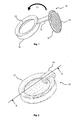
- the device according to the invention in plug form 10 consists of three distinct parts.
- This cylinder consists of a cylindrical vertical wall 121 substantially vertical.
- the body 12 has a return in the form of a circular band 122, perpendicular to the wall 121 of the body, reducing the internal diameter of the cylinder at this end. This is clearly visible on the figure 3 .
- the plug 10 further includes a valve 14.
- This valve 14 has a substantially frustoconical shape.
- the diameter of the valve 14 is smaller than the diameter of the body 12 in its widest zone. By cons, it is greater than the diameter of the body at the return 122, so that the valve can freely move in rotation inside the body 12 in the space defined by the wall 121 and support flat against the return 122. This can be observed on the figures 2 and 3 .
- the valve 14 has on one of its faces cutouts, in the form of ridges 141 rectilinear, parallel to each other. These streaks 141 here have a cross section in "V". However, striations having a cross section of different shape, such as "U” or crenellated can also be arranged.
- the ridges 141 allow the valve 14 to have improved deformation properties, localized at the bottom of the latter where the thickness of material is significantly reduced. It should be noted that a checkerboard of streaks is also possible. These properties are particularly interesting for allowing the valve to conform to the shape of the wall of the container on which it is positioned. This will be better explained below.
- the cap 10 finally comprises an arm 16 having here the shape of a rectangular parallelepiped. This arm is secured to the body 12 by one of these sides and secured to the valve 14 by the opposite side. This arm 16 plays both the role of link and articulation between the body 12 and the valve 14.
- the plug 10 is of the single-body type. It is preferably obtained by means of a traditional thermoplastic elastomer injection process.
- the plug 10 has been designed so that it can be achieved by means of an injection process as simple as possible, so as to minimize the production costs and therefore the industrial cost of said plug.
- the injection molds preferably comprise no moving parts of the drawer type.
- the molded material is flexible, it allows in some cases to consider only few ejectors, or even a single main injector, the part being removed by global deformation.
- thermoplastic elastomer injection has the advantage of being able to be implemented using a tool and a process that is less complex than an elastomer injection process requiring a hot crosslinking step. .
- the time saved in the production cycle is therefore significant.
- this thermoplastic elastomer can also be recycled by an ad hoc die , unlike crosslinked elastomers.
- thermoplastic elastomers have physico-chemical and mechanical properties of the most interesting. Their cost is lower compared to crosslinked elastomers. Which makes them materials of choice.
- Pebax® copolymers based on polyethers and amides
- Santoprene® mixturetures of ethylene propylene diene monomer and polypropylene
- Arnitel® polyyester copolymer
- Hytrel® thermoplastic polyester elastomer
- the configuration of the plug 10 according to the figure 1 is a planar configuration, as obtained at the end of the demolding step of said plug.
- the cap is not functional.
- the valve 14 bears against the inside face of the return 122, as shown in FIG. figure 3 . It is found that the diameter of the valve at the surface in contact with the return 122 is substantially greater than the diameter of the lumen of the body 12 at said return 122, so that the valve can not leave the body unless to voluntarily seek to bring it out.
- the arm 16 is held in torsion and under stress.
- the elasticity properties of the arm 16 allow the latter to exert on the valve 14 a force which tends to press said valve 14 against the return 122, in accordance with the arrow F2, thereby sealing the plug.
- the plug 10 is in a stable configuration, namely that the force exerted by the arm 16 described above and the opposite force exerted by the return 122 on the valve 14 cancel each other out.
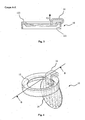
- FIGS. 4 to 6 represent the plug 10 according to the invention in the configuration in which the valve 14 is open.
- the plug 10 is shown in a configuration in which the opening of the valve 14 is near-maximum. Indeed, as can be seen in these figures, the plane in which the valve 14 is located is substantially perpendicular to the plane of the return 122. It should be noted that the opening of the flap 14 can only be obtained by the action of an external force represented on the figure 5 , by the arrow F3. Indeed, in this configuration, the elastic stress exerted on the arm 16 is almost-maximum.
- the figure 6 represents the plug 10 in "open configuration" in the case of traditional use.
- the plug 10 is here positioned on a substantially cylindrical analysis tube 18 with a circular section, so that the outer face of the wall of the tube 18 in its upper part is in contact with the inner face of the wall 121 of the plug.
- the return 122 of the cap bears on the edge of the tube 18 at the orifice of the latter.
- the thermoplastic elastomer material preferentially used for producing the stopper according to the invention has a particular advantage here, namely that it makes it possible to ensure, by virtue of its elasticity properties, a good grip of the stopper 12 on the tube 18, once the plug 12 positioned in force on the tube 18. The sealing of the tube 18 is then ensured.
- the tube 18 contains a liquid 20, which is taken out or in which another liquid is dispensed.
- a suction / discharge device 22 partially shown on the figure 6 , having at its end a plastic disposable sampling cone 24, is pressed against the valve 14 of the cap 10 in a vertical translational movement according to the arrow F4.
- the force exerted by the suction / discharge device 22 on the valve 14 via the sampling cone 24 causes the valve 14 to open, by placing the arm 16 in an elastic stress.
- the opening of the valve 14 enables the Withdrawal cone to cross the stopper and to enter the tube 18.
- all this sequence is carried out continuously, during the translational vertical displacement of the suction / discharge device 22.
- the sampling cone 24 provides the necessary force on the valve 14 to keep it open under stress.
- Displacement is interrupted when the disposable cone comes into contact with the liquid.
- the suction / discharge device 22 is an automatic device, part of an automatic biological analysis system, it is advisable to have on said system a liquid detection means to prevent the cone does not soak deep in the liquid.
- a liquid detection means to prevent the cone does not soak deep in the liquid.
- Such means are well known and widely used in such systems. It is however necessary to ensure that the liquid detection means is not activated when the cone of sampling 24 liquid with the valve 14 of the cap 10, causing the vertical translational movement of the suction / discharge device 22 to stop.
- the suction / discharge device 22 can carry out either the suction of a fraction of the liquid 20, or discharge a volume of another liquid taken previously and contained in the sampling cone 24. It should be noted that in the case of a liquid discharge, it is not necessary that the sampling cone 24 enters in contact with the liquid 20.
- the suction / discharge device 22 engages an inverse translational vertical movement until the sampling cone 24 is found outside the tube 18.
- the force exerted on the valve 14 by the withdrawal cone 24 during the raising of the suction / discharge device 22 keeps the valve 14 open under stress and until the sampling cone 24 and the valve 14 is in contact only by the end of said sampling cone 24. From this moment, thanks to the elastic return force exerted by the arm 16 on the valve 14, the latter engages its recovery concomitantly with the raising of the sampling cone 24, while remaining in contact with the end of said cone.
- the valve 14 may comprise on its upper face, namely the face opposite to the face carrying the grooves, a means (not shown) for limiting the friction between the sampling cone 24 and said valve 14, when said cone of Sampling 24 is out of the tube.
- a means can be a particular structuring of the upper face making the latter granular.
- This means can also be a boss on the upper face of the valve 14, thus limiting the contact surface between the sampling cone 24 and the valve 14.
- valve 14 in a substantially rotary movement is completed when the valve returns to the closed position, namely abutting against the return 122 of the body 12, in accordance with what is shown on the figures 2 and 3 .
- the cap is then closed and the sealing of the plug 12 is then again ensured, allowing its transport without risk of leakage of liquid.
- the plug according to the invention can be substituted for all plugs or covers positioned on a container and it is necessary to remove to reach or take the liquid container, when an optimal level of sealing is not required . Due to its configuration, the orifice released during the opening of the valve is very important, allowing the passage of large suction / discharge devices, which can be relatively flexible and non-blunt, thus limiting the risk of injury .
- the elastic return force exerted by the arm can advantageously be adapted to the desired use by adjusting the shape of the latter.
- the cap may be conceivable to manufacture the cap simultaneously with the container that it must close. Indeed, in the case of a container, such as a tube, made by injection molding, it is quite possible to consider overmolding the cap on the container during manufacture of the latter. It is then a bi-material injection process. The plug according to the invention and the container then form a monobloc device.
- the valve is positioned between two volume spaces between which fluid is to be transferred. In this case, it is the pressure exerted upstream by the fluid, which forces the opening of the valve, minimizing the pressure loss due to the diameter of the valve. In case of depression or flow reversal, the valve closes quickly.
Landscapes
- Engineering & Computer Science (AREA)
- General Engineering & Computer Science (AREA)
- Health & Medical Sciences (AREA)
- Chemical & Material Sciences (AREA)
- Mechanical Engineering (AREA)
- Analytical Chemistry (AREA)
- General Health & Medical Sciences (AREA)
- Hematology (AREA)
- Clinical Laboratory Science (AREA)
- Chemical Kinetics & Catalysis (AREA)
- Closures For Containers (AREA)
- Sampling And Sample Adjustment (AREA)
Claims (14)
- Einstückige Vorrichtung (10) mit Ventilklappe aus elastischem Material, die zwei verschiedene Volumenräume trennt, wobei die Vorrichtung aufweist:a) einen im Wesentlichen zylindrischen Körper (12), der einen Durchgangskanal aufweist,b) eine Ventilklappe (14), die die Öffnung des Durchgangskanals des Körpers (12) verschließt, wenn die Vorrichtung (10) in der geschlossenen Stellung ist, wobei die Ventilklappe (14) im Innenraum des Körpers (12) angeordnet ist,c) einen Arm (16), der den Körper (12) der Vorrichtung mit der Ventilklappe (14) verbindet, wobei der Arm (16) unabhängig von der Stellung der Ventilklappe (14) in einer gespannten elastischen Stellung ist.
- Vorrichtung nach dem vorhergehenden, Anspruch, wobei der Arm (16) den Körper (12) der Vorrichtung durch den Durchgangskanal des Körpers (12) hindurch mit der Ventilklappe (14) verbindet.
- Vorrichtung (10) nach einem der vorhergehenden Ansprüche, wobei das elastische Material aus der Gruppe genommen wird, die enthält: die thermoplastischen Elastomere; die vernetzten oder vulkanisierten Elastomere; die Silicone; Fluorsilicone; die Fluorelastomere; die Polyisoprene; die natürlichen, Butyl- oder NitrilKautschuke, die fluorkohlenwasserstoffhaltigen Polymere.
- Vorrichtung (10) nach einem der vorhergehenden Ansprüche, wobei die Ventilklappe (14) im Wesentlichen eben ist.
- Vorrichtung (10) nach einem der vorhergehenden Ansprüche, wobei die Ventilklappe (14) Verformungseinrichtungen (141) aufweist, die die Verformung der Ventilklappe (14) erleichtern.
- Vorrichtung (10) nach einem der vorhergehenden Ansprüche, wobei der Körper (12) mindestens eine Umfangslippe (122) aufweist.
- Vorrichtung (10) nach einem der vorhergehenden Ansprüche, wobei die Ventilklappe (14) Einrichtungen aufweist, die dazu bestimmt sind, das Gleiten eines die Öffnung der Ventilklappe erlaubenden Gegenstands zu erleichtern.
- Vorrichtung (10) nach einem der vorhergehenden Ansprüche, deren Körper (12) eine Form aufweist, die es ihr ermöglichen kann, sich auf einem Behälter zu positionieren.
- Vorrichtung (10) nach einem der Ansprüche 1 bis 7, deren Körper (12) eine Form aufweist, die es ihr ermöglichen kann, sich an der Schnittfläche zwischen einem Quellenbehälter und einem Zielbehälter oder zwischen einem vorderen Anschlussstutzen und einem hinteren Anschlussstutzen zu positionieren.
- Verwendung einer Vorrichtung (10) nach einem der Ansprüche 1 bis 8 als Verschluss.
- Verwendung einer Vorrichtung (10) nach einem der Ansprüche 1 bis 7 und 9 als Ventil.
- Verfahren zur Übertragung eines Fluids zwischen einem Quellenvolumenraum und einem Zielvolumenraum, wobei die zwei Volumenräume durch die als Ventil verwendete Vorrichtung (10) nach einem der Ansprüche 1 bis 7 und 9 getrennt werden, wobei das Verfahren Schritte enthält, die darin bestehen:a) mittels des zu übertragenden Fluids einen ausreichenden Druck auf die Ventilklappe (14) des Ventils auszuüben, um die Öffnung der Ventilklappe (14) zu erlauben, was zu einem elastischen Unterspannungsetzen des Arms (16) des Ventils führt;b) den Druck während einer ausreichenden Zeit aufrechtzuerhalten, um die Übertragung des gewünschten Fluidvolumens zu erlauben;c) den Druck aufzuheben, um aufgrund der vom Arm (16) des Ventils ausgeübten elastischen Rückstellkraft die Rückkehr der Ventilklappe (14) in die geschlossene Stellung zu bewirken.
- Verfahren zur Entnahme eines Teils einer in einem Behälter enthaltenen Flüssigkeitsprobe, der von einer als Verschluss verwendeten Vorrichtung (10) nach einem der Ansprüche 1 bis 8 verschlossen wird, wobei das Verfahren die Schritte enthält, die darin bestehen:a) mit Hilfe einer Ansaug-/Fördervorrichtung einen Druck auf die Ventilklappe (14) des Verschlusses auszuüben, die sich in der geschlossenen Stellung befindet, um die Öffnung dieses letzteren zu erlauben, was zu einem elastischen Unterspannungsetzen des Arms (16) des Verschlusses führt;b) die Ansaug-/Fördervorrichtung ins Innere des Behälters eindringen zu lassen, bis das Endstück der Ansaug-/Fördervorrichtung in die Flüssigkeitsprobe eingetaucht ist;c) ein bestimmtes Volumen der Flüssigkeitsprobe anzusaugen;d) die Ansaug-/Förder- oder Einführvorrichtung aus dem Behälter zu entfernen, so dass der auf die Ventilklappe (14) ausgeübte Druck aufgehoben wird, was die Rückkehr der Ventilklappe (14) in die geschlossene Stellung mit Hilfe der vom Arm (16) des Verschlusses ausgeübten elastischen Rückstellkraft bewirkt.
- Verfahren zur Ausgabe einer Flüssigkeit ins Innere eines Behälters, der von einer als Verschluss verwendeten Vorrichtung (10) nach einem der Ansprüche 1 bis 8 verschlossen wird, wobei die Flüssigkeit in einer Ansaug-/Fördervorrichtung enthalten ist, wobei das Verfahren die Schritte enthält, die darin bestehen:a) mit Hilfe einer Ansaug-/Fördervorrichtung einen Druck auf die Ventilklappe (14) des Verschlusses auszuüben, die sich in der geschlossenen Stellung befindet, um die Öffnung dieses letzteren zu erlauben, was zu einem elastischen Unterspannungsetzen des Arms (16) des Verschlusses führt;b) die Ansaug-/Fördervorrichtung ins Innere des Behälters eindringen zu lassen;c) ins Innere des Behälters ein bestimmtes Volumen der in der Ansaug-/Fördervorrichtung enthaltenen Flüssigkeit auszugeben;d) die Ansaug-/Fördervorrichtung aus dem Behälter zu entfernen, damit der auf die Ventilklappe (14) ausgeübte Druck aufgehoben wird, was zur Rückkehr der Ventilklappe (14) in die geschlossene Stellung mit Hilfe der vom Arm (16) des Verschlusses ausgeübten elastischen Rückstellkraft führt.
Applications Claiming Priority (2)
| Application Number | Priority Date | Filing Date | Title |
|---|---|---|---|
| FR1051080A FR2956463B1 (fr) | 2010-02-16 | 2010-02-16 | Dispositif a clapet, mono-corps, moule par injection de materiau elastique |
| PCT/FR2011/050319 WO2011101588A1 (fr) | 2010-02-16 | 2011-02-15 | Dispositif a clapet, mono-corps, moulé par injection de materiau elastique |
Publications (2)
| Publication Number | Publication Date |
|---|---|
| EP2536967A1 EP2536967A1 (de) | 2012-12-26 |
| EP2536967B1 true EP2536967B1 (de) | 2014-06-18 |
Family
ID=42712442
Family Applications (1)
| Application Number | Title | Priority Date | Filing Date |
|---|---|---|---|
| EP11712912.2A Active EP2536967B1 (de) | 2010-02-16 | 2011-02-15 | Aus einem elastischen material einspritzgeformte einteilige ventilvorrichtung |
Country Status (5)
| Country | Link |
|---|---|
| US (1) | US9371924B2 (de) |
| EP (1) | EP2536967B1 (de) |
| JP (1) | JP5911433B2 (de) |
| FR (1) | FR2956463B1 (de) |
| WO (1) | WO2011101588A1 (de) |
Families Citing this family (15)
| Publication number | Priority date | Publication date | Assignee | Title |
|---|---|---|---|---|
| CN102606772A (zh) * | 2012-03-16 | 2012-07-25 | 武汉东方骏驰精密制造有限公司 | 简化整体式阀门 |
| US20140134311A1 (en) * | 2012-11-13 | 2014-05-15 | Ma Wing Hong | Teabag Holder and Method |
| FI20155107A (fi) | 2015-02-19 | 2016-08-20 | Thermo Fisher Scientific Oy | Näyteastia |
| US10399749B1 (en) * | 2015-02-25 | 2019-09-03 | Robin E. Walker | Lid for a flat back bucket |
| KR101715804B1 (ko) * | 2015-06-16 | 2017-03-13 | 동부대우전자 주식회사 | 냉장고의 제빙시스템 및 제빙방법 |
| EP3341534A4 (de) * | 2015-08-24 | 2019-05-08 | Pump Pal Pty Ltd | Rückschlagventil |
| USD819897S1 (en) * | 2017-01-26 | 2018-06-05 | Donna Felton | Horse bucket and lid |
| US20200353465A1 (en) * | 2017-08-28 | 2020-11-12 | Psomagen, Inc. | Device for protecting and sealing the opening of a container |
| EP3477307B1 (de) | 2017-10-24 | 2020-07-22 | F. Hoffmann-La Roche AG | Pipettiervorrichtung und pipettiervorrichtungpositionierungssystem |
| EP3801414A1 (de) | 2018-05-29 | 2021-04-14 | Gentherm Medical, LLC | Integrierte einlassöffnungsanordnung |
| JP7051234B2 (ja) * | 2018-10-31 | 2022-04-11 | 株式会社吉野工業所 | 吐出容器 |
| US11465804B2 (en) | 2019-09-09 | 2022-10-11 | Robin E. Walker | Bucket and lid systems and apparatuses |
| KR20230041850A (ko) * | 2021-09-17 | 2023-03-27 | 삼성전자주식회사 | 밀폐 구조체 및 이를 포함하는 물질 보유 장치 |
| US11994223B2 (en) * | 2021-11-23 | 2024-05-28 | Cisco Technology, Inc. | Backflow blocking device for axial fans |
| DE102022133338A1 (de) * | 2022-12-14 | 2024-06-20 | Sisto Armaturen S.A. | Rückschlagklappe PTFE |
Family Cites Families (30)
| Publication number | Priority date | Publication date | Assignee | Title |
|---|---|---|---|---|
| US1879205A (en) * | 1931-12-08 | 1932-09-27 | Gunn Damon Mott | Valve closure |
| US3613720A (en) * | 1969-01-27 | 1971-10-19 | G & H Products Inc | Check valve assembly |
| US3749274A (en) * | 1971-08-16 | 1973-07-31 | Blessings Inc | Receptacle with spring hinge closure |
| US3952914A (en) * | 1975-02-24 | 1976-04-27 | Vogt Kuno J | Re-sealable container lid |
| JPS5480457U (de) * | 1977-11-17 | 1979-06-07 | ||
| US4138033A (en) * | 1978-01-16 | 1979-02-06 | Payne Larry E | Liquid container lid |
| US4190174A (en) * | 1979-01-29 | 1980-02-26 | Thermo-Seal, Inc. | Drinking receptacle cover with a lip operated valve |
| JPS56141261U (de) * | 1980-03-25 | 1981-10-24 | ||
| JPS62155382A (ja) * | 1985-12-26 | 1987-07-10 | Shinya Ai | 逆止弁 |
| JPH0532334Y2 (de) * | 1986-06-10 | 1993-08-19 | ||
| JPS6352052U (de) * | 1986-09-20 | 1988-04-08 | ||
| JPH04501994A (ja) * | 1988-11-28 | 1992-04-09 | ジョセフ パーソンズ ノミニーズ プロプライエタリー リミテッド | キャップ |
| US5202093A (en) * | 1991-05-20 | 1993-04-13 | Medical Robotics, Inc. | Sealing cap with a one way valve having semi-cylindrical valve closure springs |
| US5706972A (en) * | 1996-01-16 | 1998-01-13 | Sousa; Nuno J. | Self-closing beverage lid |
| FI102642B (fi) * | 1996-06-19 | 1999-01-15 | Orion Diagnostica Oy | Reaktioastian tai vastaavan tulppa |
| US7387216B1 (en) * | 1996-07-17 | 2008-06-17 | Smith James C | Closure device for containers |
| US5894950A (en) * | 1997-10-15 | 1999-04-20 | C.A.P.S. Inc. | One-piece closure with re-closable break away lid |
| US6244455B1 (en) * | 1998-04-17 | 2001-06-12 | Joseph P. Lastik | Easy opening closure member assembly for a beverage container |
| GB2342427A (en) * | 1998-10-03 | 2000-04-12 | Draftex Ind Ltd | Pipe with valve |
| US6138711A (en) * | 1999-07-07 | 2000-10-31 | Ho Lee Co., Ltd. | Air valve for an inflatable device |
| DE10105753C1 (de) * | 2001-02-08 | 2002-03-28 | Merck Patent Gmbh | Verschluß für Reagenzbehälter |
| US6783018B1 (en) * | 2001-05-25 | 2004-08-31 | Gary M. Rondeau | Lid device for a minnow bucket |
| US8302798B2 (en) * | 2001-09-04 | 2012-11-06 | Moss Christine K | Anti-spill container |
| US6805336B2 (en) * | 2002-03-04 | 2004-10-19 | Emerson Electric Co. | Self-sealing dispensing valve for humidifier water bottles |
| DE60328856D1 (de) | 2003-05-22 | 2009-10-01 | Agilent Technologies Inc | Septum mit Klappe |
| BRPI0507750B1 (pt) * | 2004-02-18 | 2017-06-13 | Sig Technology Ag SIG Technology Ltd. | Foldable closure for composite packaging and cardboard with automatic packing opening by folding to open |
| US7686182B1 (en) * | 2005-05-13 | 2010-03-30 | Rashed Shukri | Bottle cap for beverage and foodstuff containers |
| US7546931B2 (en) * | 2005-07-08 | 2009-06-16 | Becton, Dickinson And Company | Flip top cap |
| DE102007048556B3 (de) * | 2007-10-09 | 2009-02-26 | Miele & Cie. Kg | Geschirrspülmaschine |
| IL186686A0 (en) * | 2007-10-16 | 2008-02-09 | Av Doron | Normally-closed opening closure |
-
2010
- 2010-02-16 FR FR1051080A patent/FR2956463B1/fr active Active
-
2011
- 2011-02-15 JP JP2012552452A patent/JP5911433B2/ja active Active
- 2011-02-15 EP EP11712912.2A patent/EP2536967B1/de active Active
- 2011-02-15 WO PCT/FR2011/050319 patent/WO2011101588A1/fr active Application Filing
- 2011-02-15 US US13/574,729 patent/US9371924B2/en active Active
Also Published As
| Publication number | Publication date |
|---|---|
| EP2536967A1 (de) | 2012-12-26 |
| FR2956463B1 (fr) | 2012-06-29 |
| FR2956463A1 (fr) | 2011-08-19 |
| US20120298665A1 (en) | 2012-11-29 |
| US9371924B2 (en) | 2016-06-21 |
| WO2011101588A1 (fr) | 2011-08-25 |
| JP5911433B2 (ja) | 2016-04-27 |
| JP2013519594A (ja) | 2013-05-30 |
Similar Documents
| Publication | Publication Date | Title |
|---|---|---|
| EP2536967B1 (de) | Aus einem elastischen material einspritzgeformte einteilige ventilvorrichtung | |
| EP2296992B1 (de) | Vorrichtung zur ausgabe von in einem tank enthaltener flüssigkeit | |
| EP2717827B1 (de) | Vorrichtung zur Verbindung zwischen einem Empfänger und einem Gehäuse und Verfahren zur Montage und Verwendung einer solchen Vorrichtung | |
| EP2475585B1 (de) | Flüssigkeitsspender | |
| FR3036384B1 (fr) | Bouchon de distribution | |
| FR2988006A1 (fr) | Ensemble securise de transfert de liquide a usage medical | |
| CH652036A5 (fr) | Dispositif de succion et d'irrigation. | |
| EP2704852B1 (de) | Mit einem luftkanal versehene flüssigkeitsausgabevorrichtung | |
| EP3554451B1 (de) | Vorrichtung zur entnahme einer probe aus einer in einem behälter enthaltenen flüssigkeit, zugehöriger behälter und verwendung dieses behälters | |
| FR2969128A1 (fr) | Bouchon pour fermer un recipient | |
| FR2915487A1 (fr) | Ensemble et procede pour analyse microbiologique | |
| FR3026726A1 (fr) | Dispositif de conditionnement et d'application au moyen d'une pipette | |
| FR2960425A1 (fr) | Raccordement avec communication entre contenants et/ou conduits biopharmaceutiques. | |
| EP3319667B1 (de) | Spritze und verfahren zur montage davon | |
| EP1657158B1 (de) | Öffnungs- und/oder Verschliessvorrichtung für eine dichte Packung, insbesondere für Lebensmittel | |
| CH653111A5 (fr) | Vanne de commande de l'ecoulement de fluides. | |
| EP2600977A1 (de) | Endstück für eine pipettiervorrichtung mit einem teil für den schutz dieser vorrichtung | |
| WO2016071880A1 (fr) | Gobelet permettant le remplissage par le dessous et dispositif de connexion pour le globelet | |
| FR2830872A1 (fr) | Dispositif de controle microbiologique d'un echantillon de liquide sous pression | |
| EP1557124B1 (de) | Nadel-Sicherheits-Verbinder | |
| FR2952813A1 (fr) | Dispositif de liaison entre deux contenants, destine notamment a un usage medical | |
| FR3005854A1 (fr) | Embase d'un connecteur pour poche de perfusion | |
| FR3101147A1 (fr) | Récipient pour produit réactif équipé d’un tube d’aspiration | |
| FR3129274A1 (fr) | Procede et systeme de recharge en liquide d’un flacon | |
| FR2884232A1 (fr) | Recipient etanche aux liquides utilise a des fins medicales. |
Legal Events
| Date | Code | Title | Description |
|---|---|---|---|
| PUAI | Public reference made under article 153(3) epc to a published international application that has entered the european phase |
Free format text: ORIGINAL CODE: 0009012 |
|
| 17P | Request for examination filed |
Effective date: 20120725 |
|
| AK | Designated contracting states |
Kind code of ref document: A1 Designated state(s): AL AT BE BG CH CY CZ DE DK EE ES FI FR GB GR HR HU IE IS IT LI LT LU LV MC MK MT NL NO PL PT RO RS SE SI SK SM TR |
|
| DAX | Request for extension of the european patent (deleted) | ||
| REG | Reference to a national code |
Ref country code: DE Ref legal event code: R079 Ref document number: 602011007773 Country of ref document: DE Free format text: PREVIOUS MAIN CLASS: F16K0015030000 Ipc: B01L0003000000 |
|
| RIC1 | Information provided on ipc code assigned before grant |
Ipc: F16K 15/03 20060101ALI20131128BHEP Ipc: B01L 3/00 20060101AFI20131128BHEP Ipc: F16K 15/18 20060101ALI20131128BHEP |
|
| GRAP | Despatch of communication of intention to grant a patent |
Free format text: ORIGINAL CODE: EPIDOSNIGR1 |
|
| INTG | Intention to grant announced |
Effective date: 20140206 |
|
| GRAS | Grant fee paid |
Free format text: ORIGINAL CODE: EPIDOSNIGR3 |
|
| GRAA | (expected) grant |
Free format text: ORIGINAL CODE: 0009210 |
|
| AK | Designated contracting states |
Kind code of ref document: B1 Designated state(s): AL AT BE BG CH CY CZ DE DK EE ES FI FR GB GR HR HU IE IS IT LI LT LU LV MC MK MT NL NO PL PT RO RS SE SI SK SM TR |
|
| REG | Reference to a national code |
Ref country code: GB Ref legal event code: FG4D Free format text: NOT ENGLISH |
|
| REG | Reference to a national code |
Ref country code: CH Ref legal event code: EP |
|
| REG | Reference to a national code |
Ref country code: AT Ref legal event code: REF Ref document number: 673022 Country of ref document: AT Kind code of ref document: T Effective date: 20140715 |
|
| REG | Reference to a national code |
Ref country code: IE Ref legal event code: FG4D Free format text: LANGUAGE OF EP DOCUMENT: FRENCH |
|
| REG | Reference to a national code |
Ref country code: DE Ref legal event code: R096 Ref document number: 602011007773 Country of ref document: DE Effective date: 20140731 |
|
| PG25 | Lapsed in a contracting state [announced via postgrant information from national office to epo] |
Ref country code: LT Free format text: LAPSE BECAUSE OF FAILURE TO SUBMIT A TRANSLATION OF THE DESCRIPTION OR TO PAY THE FEE WITHIN THE PRESCRIBED TIME-LIMIT Effective date: 20140618 Ref country code: CY Free format text: LAPSE BECAUSE OF FAILURE TO SUBMIT A TRANSLATION OF THE DESCRIPTION OR TO PAY THE FEE WITHIN THE PRESCRIBED TIME-LIMIT Effective date: 20140618 Ref country code: FI Free format text: LAPSE BECAUSE OF FAILURE TO SUBMIT A TRANSLATION OF THE DESCRIPTION OR TO PAY THE FEE WITHIN THE PRESCRIBED TIME-LIMIT Effective date: 20140618 Ref country code: GR Free format text: LAPSE BECAUSE OF FAILURE TO SUBMIT A TRANSLATION OF THE DESCRIPTION OR TO PAY THE FEE WITHIN THE PRESCRIBED TIME-LIMIT Effective date: 20140919 Ref country code: NO Free format text: LAPSE BECAUSE OF FAILURE TO SUBMIT A TRANSLATION OF THE DESCRIPTION OR TO PAY THE FEE WITHIN THE PRESCRIBED TIME-LIMIT Effective date: 20140918 |
|
| REG | Reference to a national code |
Ref country code: NL Ref legal event code: VDEP Effective date: 20140618 |
|
| REG | Reference to a national code |
Ref country code: AT Ref legal event code: MK05 Ref document number: 673022 Country of ref document: AT Kind code of ref document: T Effective date: 20140618 |
|
| REG | Reference to a national code |
Ref country code: LT Ref legal event code: MG4D |
|
| PG25 | Lapsed in a contracting state [announced via postgrant information from national office to epo] |
Ref country code: RS Free format text: LAPSE BECAUSE OF FAILURE TO SUBMIT A TRANSLATION OF THE DESCRIPTION OR TO PAY THE FEE WITHIN THE PRESCRIBED TIME-LIMIT Effective date: 20140618 Ref country code: LV Free format text: LAPSE BECAUSE OF FAILURE TO SUBMIT A TRANSLATION OF THE DESCRIPTION OR TO PAY THE FEE WITHIN THE PRESCRIBED TIME-LIMIT Effective date: 20140618 Ref country code: SE Free format text: LAPSE BECAUSE OF FAILURE TO SUBMIT A TRANSLATION OF THE DESCRIPTION OR TO PAY THE FEE WITHIN THE PRESCRIBED TIME-LIMIT Effective date: 20140618 Ref country code: HR Free format text: LAPSE BECAUSE OF FAILURE TO SUBMIT A TRANSLATION OF THE DESCRIPTION OR TO PAY THE FEE WITHIN THE PRESCRIBED TIME-LIMIT Effective date: 20140618 |
|
| PG25 | Lapsed in a contracting state [announced via postgrant information from national office to epo] |
Ref country code: CZ Free format text: LAPSE BECAUSE OF FAILURE TO SUBMIT A TRANSLATION OF THE DESCRIPTION OR TO PAY THE FEE WITHIN THE PRESCRIBED TIME-LIMIT Effective date: 20140618 Ref country code: EE Free format text: LAPSE BECAUSE OF FAILURE TO SUBMIT A TRANSLATION OF THE DESCRIPTION OR TO PAY THE FEE WITHIN THE PRESCRIBED TIME-LIMIT Effective date: 20140618 Ref country code: ES Free format text: LAPSE BECAUSE OF FAILURE TO SUBMIT A TRANSLATION OF THE DESCRIPTION OR TO PAY THE FEE WITHIN THE PRESCRIBED TIME-LIMIT Effective date: 20140618 Ref country code: PT Free format text: LAPSE BECAUSE OF FAILURE TO SUBMIT A TRANSLATION OF THE DESCRIPTION OR TO PAY THE FEE WITHIN THE PRESCRIBED TIME-LIMIT Effective date: 20141020 Ref country code: RO Free format text: LAPSE BECAUSE OF FAILURE TO SUBMIT A TRANSLATION OF THE DESCRIPTION OR TO PAY THE FEE WITHIN THE PRESCRIBED TIME-LIMIT Effective date: 20140618 Ref country code: SK Free format text: LAPSE BECAUSE OF FAILURE TO SUBMIT A TRANSLATION OF THE DESCRIPTION OR TO PAY THE FEE WITHIN THE PRESCRIBED TIME-LIMIT Effective date: 20140618 |
|
| PG25 | Lapsed in a contracting state [announced via postgrant information from national office to epo] |
Ref country code: AT Free format text: LAPSE BECAUSE OF FAILURE TO SUBMIT A TRANSLATION OF THE DESCRIPTION OR TO PAY THE FEE WITHIN THE PRESCRIBED TIME-LIMIT Effective date: 20140618 Ref country code: NL Free format text: LAPSE BECAUSE OF FAILURE TO SUBMIT A TRANSLATION OF THE DESCRIPTION OR TO PAY THE FEE WITHIN THE PRESCRIBED TIME-LIMIT Effective date: 20140618 Ref country code: IS Free format text: LAPSE BECAUSE OF FAILURE TO SUBMIT A TRANSLATION OF THE DESCRIPTION OR TO PAY THE FEE WITHIN THE PRESCRIBED TIME-LIMIT Effective date: 20141018 Ref country code: PL Free format text: LAPSE BECAUSE OF FAILURE TO SUBMIT A TRANSLATION OF THE DESCRIPTION OR TO PAY THE FEE WITHIN THE PRESCRIBED TIME-LIMIT Effective date: 20140618 |
|
| REG | Reference to a national code |
Ref country code: DE Ref legal event code: R097 Ref document number: 602011007773 Country of ref document: DE |
|
| PLBE | No opposition filed within time limit |
Free format text: ORIGINAL CODE: 0009261 |
|
| STAA | Information on the status of an ep patent application or granted ep patent |
Free format text: STATUS: NO OPPOSITION FILED WITHIN TIME LIMIT |
|
| PG25 | Lapsed in a contracting state [announced via postgrant information from national office to epo] |
Ref country code: IT Free format text: LAPSE BECAUSE OF FAILURE TO SUBMIT A TRANSLATION OF THE DESCRIPTION OR TO PAY THE FEE WITHIN THE PRESCRIBED TIME-LIMIT Effective date: 20140618 Ref country code: DK Free format text: LAPSE BECAUSE OF FAILURE TO SUBMIT A TRANSLATION OF THE DESCRIPTION OR TO PAY THE FEE WITHIN THE PRESCRIBED TIME-LIMIT Effective date: 20140618 |
|
| 26N | No opposition filed |
Effective date: 20150319 |
|
| PG25 | Lapsed in a contracting state [announced via postgrant information from national office to epo] |
Ref country code: BE Free format text: LAPSE BECAUSE OF NON-PAYMENT OF DUE FEES Effective date: 20150228 |
|
| PG25 | Lapsed in a contracting state [announced via postgrant information from national office to epo] |
Ref country code: SI Free format text: LAPSE BECAUSE OF FAILURE TO SUBMIT A TRANSLATION OF THE DESCRIPTION OR TO PAY THE FEE WITHIN THE PRESCRIBED TIME-LIMIT Effective date: 20140618 |
|
| PG25 | Lapsed in a contracting state [announced via postgrant information from national office to epo] |
Ref country code: LU Free format text: LAPSE BECAUSE OF FAILURE TO SUBMIT A TRANSLATION OF THE DESCRIPTION OR TO PAY THE FEE WITHIN THE PRESCRIBED TIME-LIMIT Effective date: 20150215 |
|
| REG | Reference to a national code |
Ref country code: CH Ref legal event code: PL |
|
| PG25 | Lapsed in a contracting state [announced via postgrant information from national office to epo] |
Ref country code: MC Free format text: LAPSE BECAUSE OF FAILURE TO SUBMIT A TRANSLATION OF THE DESCRIPTION OR TO PAY THE FEE WITHIN THE PRESCRIBED TIME-LIMIT Effective date: 20140618 Ref country code: CH Free format text: LAPSE BECAUSE OF NON-PAYMENT OF DUE FEES Effective date: 20150228 Ref country code: LI Free format text: LAPSE BECAUSE OF NON-PAYMENT OF DUE FEES Effective date: 20150228 |
|
| REG | Reference to a national code |
Ref country code: IE Ref legal event code: MM4A |
|
| PG25 | Lapsed in a contracting state [announced via postgrant information from national office to epo] |
Ref country code: IE Free format text: LAPSE BECAUSE OF NON-PAYMENT OF DUE FEES Effective date: 20150215 |
|
| REG | Reference to a national code |
Ref country code: FR Ref legal event code: PLFP Year of fee payment: 6 |
|
| PG25 | Lapsed in a contracting state [announced via postgrant information from national office to epo] |
Ref country code: MT Free format text: LAPSE BECAUSE OF FAILURE TO SUBMIT A TRANSLATION OF THE DESCRIPTION OR TO PAY THE FEE WITHIN THE PRESCRIBED TIME-LIMIT Effective date: 20140618 |
|
| REG | Reference to a national code |
Ref country code: FR Ref legal event code: PLFP Year of fee payment: 7 |
|
| PG25 | Lapsed in a contracting state [announced via postgrant information from national office to epo] |
Ref country code: HU Free format text: LAPSE BECAUSE OF FAILURE TO SUBMIT A TRANSLATION OF THE DESCRIPTION OR TO PAY THE FEE WITHIN THE PRESCRIBED TIME-LIMIT; INVALID AB INITIO Effective date: 20110215 Ref country code: BG Free format text: LAPSE BECAUSE OF FAILURE TO SUBMIT A TRANSLATION OF THE DESCRIPTION OR TO PAY THE FEE WITHIN THE PRESCRIBED TIME-LIMIT Effective date: 20140618 Ref country code: SM Free format text: LAPSE BECAUSE OF FAILURE TO SUBMIT A TRANSLATION OF THE DESCRIPTION OR TO PAY THE FEE WITHIN THE PRESCRIBED TIME-LIMIT Effective date: 20140618 |
|
| PG25 | Lapsed in a contracting state [announced via postgrant information from national office to epo] |
Ref country code: TR Free format text: LAPSE BECAUSE OF FAILURE TO SUBMIT A TRANSLATION OF THE DESCRIPTION OR TO PAY THE FEE WITHIN THE PRESCRIBED TIME-LIMIT Effective date: 20140618 |
|
| REG | Reference to a national code |
Ref country code: FR Ref legal event code: PLFP Year of fee payment: 8 |
|
| PG25 | Lapsed in a contracting state [announced via postgrant information from national office to epo] |
Ref country code: MK Free format text: LAPSE BECAUSE OF FAILURE TO SUBMIT A TRANSLATION OF THE DESCRIPTION OR TO PAY THE FEE WITHIN THE PRESCRIBED TIME-LIMIT Effective date: 20140618 |
|
| PG25 | Lapsed in a contracting state [announced via postgrant information from national office to epo] |
Ref country code: AL Free format text: LAPSE BECAUSE OF FAILURE TO SUBMIT A TRANSLATION OF THE DESCRIPTION OR TO PAY THE FEE WITHIN THE PRESCRIBED TIME-LIMIT Effective date: 20140618 |
|
| PGFP | Annual fee paid to national office [announced via postgrant information from national office to epo] |
Ref country code: FR Payment date: 20230223 Year of fee payment: 13 |
|
| PGFP | Annual fee paid to national office [announced via postgrant information from national office to epo] |
Ref country code: GB Payment date: 20230227 Year of fee payment: 13 Ref country code: DE Payment date: 20230223 Year of fee payment: 13 |