EP2535500A2 - Führungselement zum Führen von Lamellen entlang einer Führungsschiene bei Rafflamellenstoren - Google Patents
Führungselement zum Führen von Lamellen entlang einer Führungsschiene bei Rafflamellenstoren Download PDFInfo
- Publication number
- EP2535500A2 EP2535500A2 EP12405039A EP12405039A EP2535500A2 EP 2535500 A2 EP2535500 A2 EP 2535500A2 EP 12405039 A EP12405039 A EP 12405039A EP 12405039 A EP12405039 A EP 12405039A EP 2535500 A2 EP2535500 A2 EP 2535500A2
- Authority
- EP
- European Patent Office
- Prior art keywords
- guide
- guide pin
- guide element
- pin
- guide rail
- Prior art date
- Legal status (The legal status is an assumption and is not a legal conclusion. Google has not performed a legal analysis and makes no representation as to the accuracy of the status listed.)
- Granted
Links
Images

Classifications
-
- E—FIXED CONSTRUCTIONS
- E06—DOORS, WINDOWS, SHUTTERS, OR ROLLER BLINDS IN GENERAL; LADDERS
- E06B—FIXED OR MOVABLE CLOSURES FOR OPENINGS IN BUILDINGS, VEHICLES, FENCES OR LIKE ENCLOSURES IN GENERAL, e.g. DOORS, WINDOWS, BLINDS, GATES
- E06B9/00—Screening or protective devices for wall or similar openings, with or without operating or securing mechanisms; Closures of similar construction
- E06B9/24—Screens or other constructions affording protection against light, especially against sunshine; Similar screens for privacy or appearance; Slat blinds
- E06B9/26—Lamellar or like blinds, e.g. venetian blinds
- E06B9/28—Lamellar or like blinds, e.g. venetian blinds with horizontal lamellae, e.g. non-liftable
- E06B9/30—Lamellar or like blinds, e.g. venetian blinds with horizontal lamellae, e.g. non-liftable liftable
- E06B9/32—Operating, guiding, or securing devices therefor
- E06B9/327—Guides for raisable lamellar blinds with horizontal lamellae
-
- E—FIXED CONSTRUCTIONS
- E06—DOORS, WINDOWS, SHUTTERS, OR ROLLER BLINDS IN GENERAL; LADDERS
- E06B—FIXED OR MOVABLE CLOSURES FOR OPENINGS IN BUILDINGS, VEHICLES, FENCES OR LIKE ENCLOSURES IN GENERAL, e.g. DOORS, WINDOWS, BLINDS, GATES
- E06B9/00—Screening or protective devices for wall or similar openings, with or without operating or securing mechanisms; Closures of similar construction
- E06B9/56—Operating, guiding or securing devices or arrangements for roll-type closures; Spring drums; Tape drums; Counterweighting arrangements therefor
- E06B9/58—Guiding devices
- E06B9/582—Means to increase gliss, light, sound or thermal insulation
Definitions
- the invention relates to a guide element for guiding slats along a guide rail in Rafflamellenstoren according to the preamble of patent claim 1.
- Rafflamellenstoren include a curtain with elongated slats. On one or both narrow sides of these slats protrudes a guide pin or generally a guide element. Each of the guide elements protrudes into a guide groove, which is formed on the respectively adjacent guide rail.
- the guide rails are vertically aligned and installed at a small distance of the lamella narrow sides fixed to a building.
- the lamellae are supported by flexible turning elements which are fixed at regular intervals on each of the two longitudinal edges of the lamellae.
- a support rail is arranged on which the slats can be stacked up or down when opening and closing the curtain. In general, the support rail is held by flexible support elements or support cords.
- the support rail can be pulled up to open the curtain and to close the Be lowered.
- the slats are moved in the direction of the guide rails and thereby guided by the engagement of the guide pins in the guide grooves.
- the guide pins have sufficient clearance, so that disturbances can be largely prevented by jamming or jamming.
- slats that are not stacked on the mounting rail hang on the reversing straps.
- the non-stacked lamellae can be pivoted between a closed position and an open position. Since the range of motion of the slats is limited to a minimum across the level of the curtain due to the engagement of the guide pin in the guide rail, the pivot axes of the slats are essentially determined by the position of the guide pins.
- Conventional guide elements are usually made homogeneously from only one material such as zinc or plastic.
- the material is chosen so that it has good guiding properties relative to the guide rail. Due to the clearance between the guide bolts and the guide rails required for trouble-free operation of the Rafflamellenstore beat the guide pins, especially in windy weather against the guide rails. This leads to disturbing noises. to Reduction of such disturbing noises, it is known to attach to the two adjacent to the guide pin portions of the guide rail plastic Kederprofile, which extend over the entire length of the guide rail and have good sliding properties. The production of guide profiles with such Kederprofilen is relatively expensive. Although the Kederprofile have better sliding properties, a sufficient clearance between the guide pin and the Kederprofilen must be ensured. The problem of lateral abutment of the guide pins is thus not yet solved satisfactorily.
- the invention is based on the recognition that the opposing properties "good sliding” and "good noise damping” are not needed at the same time.
- the good sliding properties are desired for those slats that are moved when opening and / or closing the curtain along the guide rail, the good Vapor properties, however, in those slats, which are in a partially or fully closed pivot position and are not moved.
- the guide element is now designed so that its sliding properties and its damping properties are dependent on the respective pivot position. This can be done on the one hand by the shape or the external shape and on the other hand by the use of different materials, which - depending on the respective pivot angle - the leading edge of the guide profile are turned.
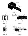
- FIG. 1 shows a portion of a vertically oriented guide rail 1, with a displaceable and pivotally mounted therein guide element 3.
- the guide rail 1 may be formed, for example, aluminum extruded profile with a substantially C-shaped cross-section and includes one of two leading edges 5 limited, in the longitudinal direction of Guide rail 1 extending guide gap 7 and a correspondingly formed guide.
- the guide member 3 comprises on one side a mounting portion 9 for fixing to the narrow end of a blade (not shown) and on the other side a guide pin 11, which the fin end in overhung state and protrudes through the guide gap 7 in the guide rail 1.
- the attachment portion 9 may, for example, as in the illustrated embodiment, a contact surface 13 and two outstanding frusto-conical nubs 15 include.
- a shoulder 17 projecting beyond the contact surface 13 between the guide pin 11 and the contact surface 13 serves as a stop body for the slat edge when the guide element 3 is fastened to the slat.
- the knobs 15 are inserted into corresponding holes in the fin end (not shown).
- the connection of the guide element 3 with the blade can be done for example by welding or riveting.
- FIGS. 1 to 5 illustrate pivotal position of the guide element 3 from different directions.
- FIG. 3 and in particular the in FIG. 4 illustrated cross-section of the guide pin 11 along the line AA in FIG. 3 show a deviating from the circular shape cross-sectional shape and a structure of the guide pin 11 of several Components.
- the guide pin 11 has direction-dependent dimensions or outer diameter in a section which can be guided between the guide edges 5.
- the diameter D1 in the direction predetermined by the contact surface 13 for the lamella is smaller than the diameter D2 orthogonal or transversely to the direction of the abutment surface 13. This causes the maximum gap width S1 between the guide pin 11 and the adjacent leading edge 5 in the Closure of the lamella or curtain ( FIG. 5 ) is smaller than the maximum gap width S2 between the guide pin 11 and the adjacent leading edge 5 in the open position of the slats ( FIG. 10 ).
- the FIGS. 6 to 10 correspond to the FIGS. 1 to 5 However, wherein the curtain or the lamella and thus also the guide element 3 is in the open position.
- the first material 19 has good sliding properties
- the second material 21 has good sound-damping or vibration-absorbing or elastically resilient properties.
- the one or more areas made of the first material 19 are arranged on the guide pin 11 that they nearer at pivotal positions of the guide pin 11, in which the slats are fully open the guide edges 5 are as the one or more of the second material 21 manufactured areas. In the case of fully closed lamellae and preferably also in the case of partially closed lamellae or in the case of pivoting positions of the lamellae between the open position and the closed position, this does not apply.
- the areas or areas made of the second material 21 of the guide pin 11 with the good sound-damping properties are closer to the guide edges 5 than those made of the first material 19 areas.
- the guide pin 11 and the game or the maximum distance to the adjacent leading edge 5 minimal.
- the inner end of the guide member 3 comprises a flange 23, with respect to the adjacent part of the guide pin 11 enlarged radial dimensions.
- the flange 23 is designed so that it strikes in the direction of the pin axis of the inside of the guide edges 5 comprehensive legs of the guide rail 1 during movements of the guide element 3 and so the range of motion the lamella is limited in the direction of the pin axis.
- the flange 23 comprises a notch or groove 25 (FIG. FIG. 10 ) and one of the groove 25 diametrically opposite, downwardly projecting nose 27 (FIG. FIG. 7 ).
- the lugs 27 engage in the grooves 25 of the respectively adjacent lower guide elements 3.
- the groove 25 is sufficiently deep and extends as a groove 25 '(FIG. FIG. 10 ) in the region of the adjacent guide pin 11, such that the lamellae are slightly displaceable in their longitudinal direction during stacking relative to one another.
- the guide pin 11 may for example comprise a cross-sectionally H-shaped region, which is made of the shock-absorbing second material 21.
- the first material 19 may, for example - as in the FIGS. 4 and 9 shown - on both sides adjacent to the two legs of the fabric made of the second material 21 may be arranged and include convex curvatures.
- the two upper ends of the H-shaped, made of the second material 21 limit the area formed on the guide pin 11 groove 25 'which is arranged in alignment with the groove 23 formed on the flange 23.
Landscapes
- Engineering & Computer Science (AREA)
- Structural Engineering (AREA)
- Architecture (AREA)
- Civil Engineering (AREA)
- Operating, Guiding And Securing Of Roll- Type Closing Members (AREA)
- Blinds (AREA)
Abstract
Description
- Gegenstand der Erfindung ist ein Führungselement zum Führen von Lamellen entlang einer Führungsschiene bei Rafflamellenstoren gemäss dem Oberbegriff des Patentanspruchs 1.
- Rafflamellenstoren umfassen einen Behang mit länglichen Lamellen. An einer oder an beiden Schmalseiten dieser Lamellen ragt ein Führungsbolzen oder allgemein ein Führungselement hervor. Jedes der Führungselemente ragt in eine Führungsnut hinein, welche an der jeweils benachbarten Führungsschiene ausgebildet ist. In der Regel sind die Führungsschienen vertikal ausgerichtet und in geringem Abstand der Lamellenschmalseiten ortsfest an einem Gebäude installiert. Die Lamellen sind von flexiblen Wendeelementen bzw. Wendeschnüren getragen, die in gleichmässigen Abständen an jeder der beiden Längskanten der Lamellen befestigt sind. Unterhalb der untersten Lamelle ist eine Tragschiene angeordnet, auf der die Lamellen beim Öffnen und Schliessen des Behangs auf- bzw. abgestapelt werden können. In der Regel ist die Tragschiene von flexiblen Tragelementen bzw. Tragschnüren gehalten. An diesen Tragschnüren kann die Tragschiene zum Öffnen des Behangs hochgezogen und zum Schliessen des Behangs abgesenkt werden. Beim Auf- und Abstapeln werden die Lamellen in Richtung der Führungsschienen verschoben und dabei durch den Eingriff der Führungsbolzen in die Führungsnuten geführt. Innerhalb der Führungsnut haben die Führungsbolzen ausreichend Spiel, sodass Störungen durch Verkanten oder Verklemmen weitgehend verhindert werden können.
- Jene Lamellen, die nicht auf der Tragschiene aufgestapelt sind, hängen an den Wendeschnüren. Durch gegenläufiges Hochziehen bzw. Absenken der Wendeschnüre an den beiden gegenüberliegenden Seiten des Behangs können die nicht aufgestapelten Lamellen zwischen einer Schliessstellung und einer Offenstellung verschwenkt werden. Da der Bewegungsspielraum der Lamellen quer zur Ebene des Behangs aufgrund des Eingriffs der Führungsbolzen in die Führungsschiene auf ein Minimum begrenzt ist, sind die Schwenkachsen der Lamellen im Wesentlichen durch die Lage der Führungsbolzen vorgegeben.
- Herkömmliche Führungselemente sind in der Regel homogen aus nur einem Material wie beispielsweise Zink oder Kunststoff hergestellt. Das Material wird so gewählt dass es relativ zur Führungsschiene gute Geleiteigenschaften aufweist. Aufgrund des für einen störungsfreien Betrieb der Rafflamellenstore erforderlichen Spiels zwischen den Führungsbolzen und den Führungsschienen schlagen die Führungsbolzen insbesondere bei windigem Wetter gegen die Führungsschienen. Dies führt zu störenden Geräuschen. Zur Verringerung solcher störender Geräusche ist es bekannt, an den beiden an den Führungsbolzen angrenzenden Abschnitten der Führungsschiene Kunststoff-Kederprofile anzubringen, welche sich über die gesamte Länge der Führungsschiene erstrecken und gute Gleiteigenschaften aufweisen. Die Herstellung von Führungsprofilen mit solchen Kederprofilen ist vergleichsweise teuer. Obwohl die Kederprofile bessere Gleiteigenschaften aufweisen, muss ein ausreichendes Spiel zwischen den Führungsbolzen und den Kederprofilen sichergestellt werden. Das Problem des seitlichen Anschlagens der Führungsbolzen ist somit noch nicht zufriedenstellend gelöst.
- Es ist deshalb eine Aufgabe der vorliegenden Erfindung, ein Führungselement zu schaffen, welches kostengünstig herstellbar ist, gute Gleiteigenschaften und verbesserte Geräuschdämmungseigenschaften aufweist.
- Diese Aufgabe wird gelöst durch ein Führungselement gemäss den Merkmalen des Patentanspruchs 1.
- Die Erfindung beruht auf der Erkenntnis, dass die gegenläufigen Eigenschaften "gutes Gleiten" und "gute Geräuschdämpfung" nicht gleichzeitig benötigt werden. So sind die guten Gleiteigenschaften bei jenen Lamellen erwünscht, die beim Öffnen und/oder Schliessen des Behangs entlang der Führungsschiene verschoben werden, die guten Dämpfeigenschaften hingegen bei jenen Lamellen, die in einer teilweise oder vollständig geschlossenen Schwenkstellung sind und nicht verschoben werden. Beim Anheben und Absenken sind die Lamellen horizontal gestellt. Ist der Behang in der gewünschten Absenklage, werden die Lamellen vollständig geschlossen oder in die gewünschte Schwenklage zwischen der horizontalen Offenstellung und der vertikalen Schliessstellung gebracht. Erfindungsgemäss ist das Führungselement nun so ausgebildet, dass seine Gleiteigenschaften und seine Dämpfungseigenschaften abhängig von der jeweiligen Schwenklage sind. Dies kann einerseits durch die Formgebung bzw. die äussere Gestalt erfolgen und andererseits durch die Verwendung unterschiedlicher Materialien, die - abhängig vom jeweiligen Schwenkwinkel - der Führungskante des Führungsprofils zugewendet sind.
- Anhand einiger Figuren wird die Erfindung im Folgenden näher beschrieben. Dabei zeigen
- Figur 1
- Eine perspektivisch Detailansicht eines Abschnitts einer Führungsschiene mit einem darin geführten Führungselement in einer der Schliessstellung entsprechenden ersten Schwenklage,
- Figur 2
- eine Seitenansicht der Anordnung aus
Figur 1 - Figur 3
- eine Frontansicht der Anordnung aus
Figur 1 - Figur 4
- einen Querschnitt des Führungselements entlang der Linie A-A in
Figur 3 - Figur 5
- eine Aufsicht auf die Anordnung aus
Figur 1 - Figur 6
- Eine perspektivisch Detailansicht der Anordnung aus
Figur 1 , wobei das Führungselement in eine der Offenstellung entsprechende zweite Schwenklage verschwenkt ist, - Figur 7
- eine Seitenansicht der Anordnung aus
Figur 6 - Figur 8
- eine Frontansicht der Anordnung aus
Figur 6 - Figur 9
- einen Querschnitt des Führungselements entlang der Linie B-B in
Figur 8 - Figur 10
- eine Aufsicht auf die Anordnung aus
Figur 6 . -
Figur 1 zeigt einen Abschnitt einer vertikal ausgerichteten Führungsschiene 1, mit einem darin verschiebbar und schwenkbar gelagerten Führungselement 3. Die Führungsschiene 1 kann z.B. aus Aluminium als Strangprofil mit einem im Wesentlichen C-förmigen Querschnitt ausgebildet sein und umfasst einen von zwei Führungskanten 5 begrenzten, in Längsrichtung der Führungsschiene 1 verlaufenden Führungsspalt 7 bzw. eine entsprechend ausgebildete Führungsnut. - Das Führungselement 3 umfasst auf der einen Seite einen Befestigungsabschnitt 9 zum Befestigen am schmalseitigen Ende einer Lamelle (nicht dargestellt) und auf der anderen Seite einen Führungsbolzen 11, der das Lamellenende im montierten Zustand überragt und durch den Führungsspalt 7 in die Führungsschiene 1 hineinragt. Der Befestigungsabschnitt 9 kann z.B. wie bei der dargestellten Ausführungsform eine Anlagefläche 13 und zwei daran hervorragende kegelstumpfartige Noppen 15 umfassen. Eine die Anlagefläche 13 überragende Schulter 17 zwischen dem Führungsbolzen 11 und der Anlagefläche 13 dient beim Befestigen des Führungselements 3 an der Lamelle als Anschlagkörper für die Lamellenkante. Die Noppen 15 werden in entsprechende Bohrungen am Lamellenende eingesteckt (nicht dargestellt). Die Verbindung des Führungselements 3 mit der Lamelle kann z.B. durch Schweissen oder Nieten erfolgen. Da die Lamelle fest mit dem Führungselement 3 verbunden ist und an dessen Anlagefläche 13 anliegt, entspricht die Schwenklage des Führungselements 3 jener der Lamellen (nicht dargestellt). In der in den
Figuren 1 bis 5 dargestellten Schwenklage des Führungselements 3 wäre die Lamelle in ihrer Schliessstellung. DieFiguren 2, 3 und 5 zeigen Ansichten dieser Schwenklage des Führungselements 3 aus unterschiedlichen Blickrichtungen. Bei der Seitenansicht gemässFigur 2 ist die etwa parallel zu den Führungskanten 5 ausgerichtete Anlagefläche 13 gut erkennbar.Figur 3 und insbesondere der inFigur 4 dargestellte Querschnitt des Führungsbolzens 11 entlang der Linie A-A inFigur 3 zeigen eine von der Kreisform abweichende Querschnittform und einen Aufbau des Führungsbolzens 11 aus mehreren Komponenten. Der Führungsbolzen 11 hat in einem zwischen den Führungskanten 5 führbaren Abschnitt richtungsabhängige Abmessungen bzw. Aussendurchmesser. Der Durchmesser D1 in der durch die Anlagefläche 13 für die Lamelle vorgegebenen Richtung ist kleiner ist als der Durchmesser D2 orthogonal bzw. quer zur Richtung der Anlagefläche 13. Dies bewirkt, dass die maximale Spaltbreite S1 zwischen dem Führungsbolzen 11 und der benachbarten Führungskante 5 in der Schliessstellung der Lamelle bzw. des Behangs (Figur 5 ) kleiner ist als die maximale Spaltbreite S2 zwischen dem Führungsbolzen 11 und der benachbarten Führungskante 5 in der Offenstellung der Lamellen (Figur 10 ). DieFiguren 6 bis 10 entsprechen denFiguren 1 bis 5 , wobei jedoch der Behang bzw. die Lamelle und somit auch das Führungselement 3 in der Offenstellung ist.Figur 9 zeigt entsprechend einen Querschnitt des Führungsbolzens 11 entlang der Linie B-B inFigur 8 . Alternativ oder zusätzlich zur Formgebung kann der Führungsbolzen 11 auch aus zwei Materialien mit unterschiedlichen Eigenschaften gefertigt sein. Das erste Material 19 hat gute Gleiteigenschaften, das zweite Material 21 gute schalldämpfende bzw. schwingungsabsorbierende oder elastisch federnde Eigenschaften. Der bzw. die aus dem ersten Material 19 gefertigten Bereiche sind so am Führungsbolzen 11 angeordnet, dass sie bei Schwenklagen des Führungsbolzens 11, bei denen die Lamellen ganz geöffnet sind, näher bei den Führungskanten 5 liegen als der bzw. die aus dem zweiten Material 21 gefertigten Bereiche. Bei vollständig geschlossenen Lamellen und vorzugsweise auch bei teilweise geschlossenen Lamellen bzw. bei Schwenkstellungen der Lamellen zwischen der Offenstellung und der Schliessstellung gilt dies nicht. Bei geschlossenem Behang bzw. bei einer für die Schliessstellung der Lamellen bestimmten Schwenklage der Führungselemente 3 liegen der bzw. die aus dem zweiten Material 21 gefertigten Bereiche des Führungsbolzens 11 mit den guten schalldämpfenden Eigenschaften näher bei den Führungskanten 5 als die aus dem ersten Material 19 gefertigten Bereiche. Vorzugsweise ist in dieser Schwenkstellung des Führungsbolzens 11 auch das Spiel bzw. der maximale Abstand zu den benachbarten Führungskanten 5 minimal. Dadurch können Bewegungen der Führungselemente 3 quer zur Verschieberichtung des Behangs sowie Anschlaggeräusche beim Auftreffen der Führungsbolzen 11 auf die Führungskanten 5 der Führungsschiene 1 minimiert werden. - Wie aus den
Figuren 5 ,6, 7 und 10 ersichtlich, umfasst das innere Ende des Führungselements 3 einen Flansch 23, mit im Vergleich zum angrenzenden Teil des Führungsbolzens 11 vergrösserten radialen Abmessungen. Der Flansch 23 ist so ausgebildet, dass er bei Bewegungen des Führungselementes 3 in Richtung der Bolzenachse von innen her an den die Führungskanten 5 umfassenden Schenkeln der Führungsschiene 1 anschlägt und so den Bewegungsspielraum der Lamelle in Richtung der Bolzenachse begrenzt. Der Flansch 23 umfasst eine bei offener Schwenklage der Lamelle oben liegende Kerbe oder Nut 25 (Figur 10 ) und eine der Nut 25 diametral gegenüberliegende, nach unten vorstehende Nase 27 (Figur 7 ). Werden die Lamellen beim Öffnen des Behangs gestapelt, so greifen die Nasen 27 in die Nuten 25 der jeweils benachbarten unteren Führungselemente 3 ein. Auf diese Weise können die benachbarten Lamellen relativ zueinander in Richtung ihrer Schmalseiten ausgerichtet werden. Vorzugsweise ist die Nut 25 ausreichend tief und erstreckt sich als Nut 25' (Figur 10 ) in den Bereich des angrenzenden Führungsbolzens 11, derart, dass die Lamellen beim Stapeln relativ zueinander in ihrer Längsrichtung geringfügig verschiebbar sind. - Der Führungsbolzen 11 kann beispielsweise einen im Querschnitt H-förmigen Bereich umfassen, der aus dem stossdämpfenden zweiten Material 21 gefertigt ist. Das erste Material 19 kann beispielsweise - wie in den
Figuren 4 und9 dargestellt - beidseitig angrenzend an die beiden Schenkel des aus dem zweiten Material 21 gefertigten Bereichs angeordnet sein und konvexe Wölbungen umfassen. Vorzugsweise begrenzen die beiden oberen Enden des H-förmigen, aus dem zweiten Material 21 gefertigten Bereichs die am Führungsbolzen 11 ausgebildete Nut 25' welche mit der am Flansch 23 ausgebildeten Nut 25 fluchtend angeordnet ist.
Claims (7)
- Führungselement (3) zum Führen von Lamellen entlang einer Führungsschiene (1) bei Rafflamellenstoren, umfassend einen zum Befestigen an der Stirnseite einer Lamelle ausgebildeten Befestigungsabschnitt (9) und einen im montierten Zustand am Lamellenende hervorragenden und in einen von zwei Führungskanten (5) begrenzten Führungsspalt (7) der Führungsschiene (1) hineinragenden, entlang dieser Führungsschiene (1) verschiebbaren und schwenkbaren Führungsbolzen (11), dadurch gekennzeichnet, dass der Führungsbolzen (11) von seiner jeweiligen Schwenklage abhängige Mittel zur Geräuschminimierung umfasst.
- Führungselement (3) nach Anspruch 1, dadurch gekennzeichnet, dass die Mittel zur Geräuschminimierung einen zwischen den Führungskanten (5) führbaren Abschnitt des Führungsbolzens (11) umfassen, der eine von der Kreisform abweichende Querschnittsform mit einem richtungsabhängigen Aussendurchmesser aufweist.
- Führungselement (3) nach einem der Ansprüche 1 oder 2, wobei dieses Führungselement (3) eine Anlagefläche (13) zum Anlegen und Befestigen der Lamelle umfasst, dadurch gekennzeichnet, dass der Aussendurchmesser D1 des Führungsbolzens (11) in der durch die Anlagefläche (13) vorgegebenen Richtung kleiner ist als der Aussendurchmesser D2 des Führungsbolzens (11) quer zu dieser Richtung.
- Führungselement (3) nach einem der Ansprüche 1 bis 3, dadurch gekennzeichnet, dass der Führungsbolzen (11) mindestens einen Bereich aus einem ersten Material (19) mit guten Gleiteigenschaften und mindestens einen Bereich aus einem zweiten Material (21) mit guten schwingungsdämpfenden Eigenschaften umfasst.
- Führungselement (3) nach Anspruch 4, dadurch gekennzeichnet, dass der bzw. die aus dem zweiten Material (21) gefertigten Bereiche so am Führungsbolzen (11) angeordnet sind, dass sie in der Schliessstellung der Lamelle einen minimalen Abstand zu den benachbarten Führungskanten (5) der Führungsschiene (1) aufweisen.
- Führungselement (3) nach einem der Ansprüche 1 bis 5, dadurch gekennzeichnet, dass am inneren Ende des Führungsbolzens (11) ein Flansch (23) ausgebildet ist, der den Führungsbolzen (11) radial überragt, und dass dieser Flansch (23) eine bei Offenstellung der Lamelle oben liegende Nut (25) und eine unten hervorragende Nase (27) zum gegenseitigen Ausrichten benachbarter Lamellen beim Stapeln umfasst.
- Führungselement (3) nach Anspruch 6, dadurch gekennzeichnet, dass der an den Flansch (23) angrenzende Bereich des Führungsbolzens (11) eine mit der Nut (25) des Flansches (23) fluchtende Nut (25') umfasst.
Applications Claiming Priority (1)
| Application Number | Priority Date | Filing Date | Title |
|---|---|---|---|
| CH00696/11A CH704848A1 (de) | 2011-04-20 | 2011-04-20 | Führungselement zum Führen von Lamellen entlang einer Führungsschiene bei Rafflamellenstoren. |
Publications (3)
| Publication Number | Publication Date |
|---|---|
| EP2535500A2 true EP2535500A2 (de) | 2012-12-19 |
| EP2535500A3 EP2535500A3 (de) | 2015-03-25 |
| EP2535500B1 EP2535500B1 (de) | 2017-03-01 |
Family
ID=46046083
Family Applications (1)
| Application Number | Title | Priority Date | Filing Date |
|---|---|---|---|
| EP12405039.4A Active EP2535500B1 (de) | 2011-04-20 | 2012-04-18 | Führungselement zum Führen von Lamellen entlang einer Führungsschiene bei Rafflamellenstoren |
Country Status (3)
| Country | Link |
|---|---|
| EP (1) | EP2535500B1 (de) |
| CH (1) | CH704848A1 (de) |
| ES (1) | ES2625958T3 (de) |
Family Cites Families (6)
| Publication number | Priority date | Publication date | Assignee | Title |
|---|---|---|---|---|
| DE7333934U (de) * | 1973-12-13 | Rau D | Fuhrungsglied für Lamellen von Jalousien oder dgl | |
| DE7427884U (de) * | 1974-11-21 | Rau D | Führungsglied für Lamellen von Jalousien oder dgl | |
| US2174249A (en) * | 1936-05-14 | 1939-09-26 | H B Dodge And Company | Venetian blind |
| AT378405B (de) * | 1983-02-04 | 1985-08-12 | Treiber Metallbau | Lamelle fuer eine jalousie |
| DE10218581A1 (de) * | 2002-04-26 | 2003-11-13 | Warema Kunststofftechnik Und M | Raffstore mit Führungsschienen |
| DE102008055745B4 (de) * | 2008-11-04 | 2019-08-01 | Roma Kg | Lamellenführungsbolzen einer Lamelle einer Gebäudeöffnungsbeschattungsvorrichtung und Gebäudeöffnungsbeschattungsvorrichtung |
-
2011
- 2011-04-20 CH CH00696/11A patent/CH704848A1/de not_active Application Discontinuation
-
2012
- 2012-04-18 EP EP12405039.4A patent/EP2535500B1/de active Active
- 2012-04-18 ES ES12405039.4T patent/ES2625958T3/es active Active
Also Published As
| Publication number | Publication date |
|---|---|
| EP2535500B1 (de) | 2017-03-01 |
| CH704848A1 (de) | 2012-10-31 |
| ES2625958T3 (es) | 2017-07-21 |
| EP2535500A3 (de) | 2015-03-25 |
Similar Documents
| Publication | Publication Date | Title |
|---|---|---|
| EP2724071B1 (de) | Lamellenabdeckung und federelement für eine lamellenabdeckung | |
| DE10236648A1 (de) | Schnellaufendes Industrietor mit flexiblem Behang | |
| WO1994002705A1 (de) | Jalousierbarer rolladen | |
| EP2060729B1 (de) | Eckdichtung für einen Fensterflügel oder ein Türblatt | |
| EP1944460A1 (de) | Rolltor mit einer Führungseinrichtung | |
| DE69606561T2 (de) | Abschirmvorrichtung | |
| DE102006005610B4 (de) | Insektenschutzrahmen | |
| EP2535500B1 (de) | Führungselement zum Führen von Lamellen entlang einer Führungsschiene bei Rafflamellenstoren | |
| EP3963161A1 (de) | Führungsschienenbaugruppe für einen öffnungsbegrenzer, öffnungsbegrenzer mit solch einer führungsschienenbaugruppe sowie flügelanordnung mit solch einem öffnungsbegrenzer | |
| DE102006005750B4 (de) | Rollladen mit einer Mehrzahl gekoppelter Lamellen | |
| EP2366858A2 (de) | Vorrichtung zum Verschliessen einer Öffnung | |
| DE102009022827B4 (de) | Brandschutz- und/oder Rauchschutzschiebetür | |
| EP2754844A2 (de) | Lamellensystem | |
| EP2784262B1 (de) | Schrank mit Rollo | |
| EP3263825B1 (de) | Raffstore | |
| EP2233679B1 (de) | Raff-Lamellenstore für Dreieckfenster | |
| EP3736390B1 (de) | Lamellendach mit reibelement | |
| EP2474699A2 (de) | Blendschutz-Rollladen | |
| DE102008055745A1 (de) | Beschattungsvorrichtung und Lamellenführungsbolzen | |
| EP2921637B1 (de) | Lamelle und lamellenjalousie | |
| DE202010005442U1 (de) | Rollladen oder Rolltor | |
| EP3388612B1 (de) | Vorrichtung und verfahren zur abdeckung eines gebäudebereichs, insbesondere eines fensters eines gebäudes | |
| DE202016008096U1 (de) | Gebäudeabschlussantriebsvorrichtung | |
| EP3015627B1 (de) | Rastvorrichtung für ein fenster oder eine tür | |
| EP2629027A1 (de) | Flexibles Raumbelüftungssystem |
Legal Events
| Date | Code | Title | Description |
|---|---|---|---|
| PUAI | Public reference made under article 153(3) epc to a published international application that has entered the european phase |
Free format text: ORIGINAL CODE: 0009012 |
|
| AK | Designated contracting states |
Kind code of ref document: A2 Designated state(s): AL AT BE BG CH CY CZ DE DK EE ES FI FR GB GR HR HU IE IS IT LI LT LU LV MC MK MT NL NO PL PT RO RS SE SI SK SM TR |
|
| AX | Request for extension of the european patent |
Extension state: BA ME |
|
| PUAL | Search report despatched |
Free format text: ORIGINAL CODE: 0009013 |
|
| AK | Designated contracting states |
Kind code of ref document: A3 Designated state(s): AL AT BE BG CH CY CZ DE DK EE ES FI FR GB GR HR HU IE IS IT LI LT LU LV MC MK MT NL NO PL PT RO RS SE SI SK SM TR |
|
| AX | Request for extension of the european patent |
Extension state: BA ME |
|
| RIC1 | Information provided on ipc code assigned before grant |
Ipc: E06B 9/58 20060101ALI20150217BHEP Ipc: E06B 9/327 20060101AFI20150217BHEP |
|
| 17P | Request for examination filed |
Effective date: 20150526 |
|
| RBV | Designated contracting states (corrected) |
Designated state(s): AL AT BE BG CH CY CZ DE DK EE ES FI FR GB GR HR HU IE IS IT LI LT LU LV MC MK MT NL NO PL PT RO RS SE SI SK SM TR |
|
| GRAP | Despatch of communication of intention to grant a patent |
Free format text: ORIGINAL CODE: EPIDOSNIGR1 |
|
| STAA | Information on the status of an ep patent application or granted ep patent |
Free format text: STATUS: GRANT OF PATENT IS INTENDED |
|
| INTG | Intention to grant announced |
Effective date: 20161129 |
|
| GRAS | Grant fee paid |
Free format text: ORIGINAL CODE: EPIDOSNIGR3 |
|
| GRAA | (expected) grant |
Free format text: ORIGINAL CODE: 0009210 |
|
| STAA | Information on the status of an ep patent application or granted ep patent |
Free format text: STATUS: THE PATENT HAS BEEN GRANTED |
|
| AK | Designated contracting states |
Kind code of ref document: B1 Designated state(s): AL AT BE BG CH CY CZ DE DK EE ES FI FR GB GR HR HU IE IS IT LI LT LU LV MC MK MT NL NO PL PT RO RS SE SI SK SM TR |
|
| REG | Reference to a national code |
Ref country code: GB Ref legal event code: FG4D Free format text: NOT ENGLISH |
|
| REG | Reference to a national code |
Ref country code: CH Ref legal event code: EP Ref country code: CH Ref legal event code: NV Representative=s name: GACHNANG AG PATENTANWAELTE, CH Ref country code: AT Ref legal event code: REF Ref document number: 871577 Country of ref document: AT Kind code of ref document: T Effective date: 20170315 |
|
| REG | Reference to a national code |
Ref country code: IE Ref legal event code: FG4D Free format text: LANGUAGE OF EP DOCUMENT: GERMAN |
|
| REG | Reference to a national code |
Ref country code: DE Ref legal event code: R096 Ref document number: 502012009634 Country of ref document: DE |
|
| REG | Reference to a national code |
Ref country code: FR Ref legal event code: PLFP Year of fee payment: 6 |
|
| REG | Reference to a national code |
Ref country code: NL Ref legal event code: MP Effective date: 20170301 |
|
| REG | Reference to a national code |
Ref country code: LT Ref legal event code: MG4D |
|
| REG | Reference to a national code |
Ref country code: ES Ref legal event code: FG2A Ref document number: 2625958 Country of ref document: ES Kind code of ref document: T3 Effective date: 20170721 |
|
| PG25 | Lapsed in a contracting state [announced via postgrant information from national office to epo] |
Ref country code: HR Free format text: LAPSE BECAUSE OF FAILURE TO SUBMIT A TRANSLATION OF THE DESCRIPTION OR TO PAY THE FEE WITHIN THE PRESCRIBED TIME-LIMIT Effective date: 20170301 Ref country code: FI Free format text: LAPSE BECAUSE OF FAILURE TO SUBMIT A TRANSLATION OF THE DESCRIPTION OR TO PAY THE FEE WITHIN THE PRESCRIBED TIME-LIMIT Effective date: 20170301 Ref country code: NO Free format text: LAPSE BECAUSE OF FAILURE TO SUBMIT A TRANSLATION OF THE DESCRIPTION OR TO PAY THE FEE WITHIN THE PRESCRIBED TIME-LIMIT Effective date: 20170601 Ref country code: LT Free format text: LAPSE BECAUSE OF FAILURE TO SUBMIT A TRANSLATION OF THE DESCRIPTION OR TO PAY THE FEE WITHIN THE PRESCRIBED TIME-LIMIT Effective date: 20170301 Ref country code: GR Free format text: LAPSE BECAUSE OF FAILURE TO SUBMIT A TRANSLATION OF THE DESCRIPTION OR TO PAY THE FEE WITHIN THE PRESCRIBED TIME-LIMIT Effective date: 20170602 |
|
| PG25 | Lapsed in a contracting state [announced via postgrant information from national office to epo] |
Ref country code: RS Free format text: LAPSE BECAUSE OF FAILURE TO SUBMIT A TRANSLATION OF THE DESCRIPTION OR TO PAY THE FEE WITHIN THE PRESCRIBED TIME-LIMIT Effective date: 20170301 Ref country code: LV Free format text: LAPSE BECAUSE OF FAILURE TO SUBMIT A TRANSLATION OF THE DESCRIPTION OR TO PAY THE FEE WITHIN THE PRESCRIBED TIME-LIMIT Effective date: 20170301 Ref country code: SE Free format text: LAPSE BECAUSE OF FAILURE TO SUBMIT A TRANSLATION OF THE DESCRIPTION OR TO PAY THE FEE WITHIN THE PRESCRIBED TIME-LIMIT Effective date: 20170301 Ref country code: BG Free format text: LAPSE BECAUSE OF FAILURE TO SUBMIT A TRANSLATION OF THE DESCRIPTION OR TO PAY THE FEE WITHIN THE PRESCRIBED TIME-LIMIT Effective date: 20170601 |
|
| PG25 | Lapsed in a contracting state [announced via postgrant information from national office to epo] |
Ref country code: NL Free format text: LAPSE BECAUSE OF FAILURE TO SUBMIT A TRANSLATION OF THE DESCRIPTION OR TO PAY THE FEE WITHIN THE PRESCRIBED TIME-LIMIT Effective date: 20170301 |
|
| PG25 | Lapsed in a contracting state [announced via postgrant information from national office to epo] |
Ref country code: EE Free format text: LAPSE BECAUSE OF FAILURE TO SUBMIT A TRANSLATION OF THE DESCRIPTION OR TO PAY THE FEE WITHIN THE PRESCRIBED TIME-LIMIT Effective date: 20170301 Ref country code: SK Free format text: LAPSE BECAUSE OF FAILURE TO SUBMIT A TRANSLATION OF THE DESCRIPTION OR TO PAY THE FEE WITHIN THE PRESCRIBED TIME-LIMIT Effective date: 20170301 Ref country code: CZ Free format text: LAPSE BECAUSE OF FAILURE TO SUBMIT A TRANSLATION OF THE DESCRIPTION OR TO PAY THE FEE WITHIN THE PRESCRIBED TIME-LIMIT Effective date: 20170301 Ref country code: RO Free format text: LAPSE BECAUSE OF FAILURE TO SUBMIT A TRANSLATION OF THE DESCRIPTION OR TO PAY THE FEE WITHIN THE PRESCRIBED TIME-LIMIT Effective date: 20170301 |
|
| PG25 | Lapsed in a contracting state [announced via postgrant information from national office to epo] |
Ref country code: PL Free format text: LAPSE BECAUSE OF FAILURE TO SUBMIT A TRANSLATION OF THE DESCRIPTION OR TO PAY THE FEE WITHIN THE PRESCRIBED TIME-LIMIT Effective date: 20170301 Ref country code: SM Free format text: LAPSE BECAUSE OF FAILURE TO SUBMIT A TRANSLATION OF THE DESCRIPTION OR TO PAY THE FEE WITHIN THE PRESCRIBED TIME-LIMIT Effective date: 20170301 Ref country code: PT Free format text: LAPSE BECAUSE OF FAILURE TO SUBMIT A TRANSLATION OF THE DESCRIPTION OR TO PAY THE FEE WITHIN THE PRESCRIBED TIME-LIMIT Effective date: 20170703 Ref country code: IS Free format text: LAPSE BECAUSE OF FAILURE TO SUBMIT A TRANSLATION OF THE DESCRIPTION OR TO PAY THE FEE WITHIN THE PRESCRIBED TIME-LIMIT Effective date: 20170701 |
|
| REG | Reference to a national code |
Ref country code: DE Ref legal event code: R097 Ref document number: 502012009634 Country of ref document: DE |
|
| PLBE | No opposition filed within time limit |
Free format text: ORIGINAL CODE: 0009261 |
|
| STAA | Information on the status of an ep patent application or granted ep patent |
Free format text: STATUS: NO OPPOSITION FILED WITHIN TIME LIMIT |
|
| REG | Reference to a national code |
Ref country code: IE Ref legal event code: MM4A |
|
| PG25 | Lapsed in a contracting state [announced via postgrant information from national office to epo] |
Ref country code: MC Free format text: LAPSE BECAUSE OF FAILURE TO SUBMIT A TRANSLATION OF THE DESCRIPTION OR TO PAY THE FEE WITHIN THE PRESCRIBED TIME-LIMIT Effective date: 20170301 Ref country code: DK Free format text: LAPSE BECAUSE OF FAILURE TO SUBMIT A TRANSLATION OF THE DESCRIPTION OR TO PAY THE FEE WITHIN THE PRESCRIBED TIME-LIMIT Effective date: 20170301 |
|
| 26N | No opposition filed |
Effective date: 20171204 |
|
| GBPC | Gb: european patent ceased through non-payment of renewal fee |
Effective date: 20170601 |
|
| PG25 | Lapsed in a contracting state [announced via postgrant information from national office to epo] |
Ref country code: LU Free format text: LAPSE BECAUSE OF NON-PAYMENT OF DUE FEES Effective date: 20170418 Ref country code: SI Free format text: LAPSE BECAUSE OF FAILURE TO SUBMIT A TRANSLATION OF THE DESCRIPTION OR TO PAY THE FEE WITHIN THE PRESCRIBED TIME-LIMIT Effective date: 20170301 |
|
| REG | Reference to a national code |
Ref country code: BE Ref legal event code: MM Effective date: 20170430 |
|
| REG | Reference to a national code |
Ref country code: FR Ref legal event code: PLFP Year of fee payment: 7 |
|
| PG25 | Lapsed in a contracting state [announced via postgrant information from national office to epo] |
Ref country code: IE Free format text: LAPSE BECAUSE OF NON-PAYMENT OF DUE FEES Effective date: 20170418 Ref country code: GB Free format text: LAPSE BECAUSE OF NON-PAYMENT OF DUE FEES Effective date: 20170601 |
|
| PG25 | Lapsed in a contracting state [announced via postgrant information from national office to epo] |
Ref country code: BE Free format text: LAPSE BECAUSE OF NON-PAYMENT OF DUE FEES Effective date: 20170430 |
|
| PG25 | Lapsed in a contracting state [announced via postgrant information from national office to epo] |
Ref country code: MT Free format text: LAPSE BECAUSE OF FAILURE TO SUBMIT A TRANSLATION OF THE DESCRIPTION OR TO PAY THE FEE WITHIN THE PRESCRIBED TIME-LIMIT Effective date: 20170301 |
|
| PG25 | Lapsed in a contracting state [announced via postgrant information from national office to epo] |
Ref country code: HU Free format text: LAPSE BECAUSE OF FAILURE TO SUBMIT A TRANSLATION OF THE DESCRIPTION OR TO PAY THE FEE WITHIN THE PRESCRIBED TIME-LIMIT; INVALID AB INITIO Effective date: 20120418 |
|
| PG25 | Lapsed in a contracting state [announced via postgrant information from national office to epo] |
Ref country code: CY Free format text: LAPSE BECAUSE OF NON-PAYMENT OF DUE FEES Effective date: 20170301 |
|
| PG25 | Lapsed in a contracting state [announced via postgrant information from national office to epo] |
Ref country code: MK Free format text: LAPSE BECAUSE OF FAILURE TO SUBMIT A TRANSLATION OF THE DESCRIPTION OR TO PAY THE FEE WITHIN THE PRESCRIBED TIME-LIMIT Effective date: 20170301 |
|
| PG25 | Lapsed in a contracting state [announced via postgrant information from national office to epo] |
Ref country code: TR Free format text: LAPSE BECAUSE OF FAILURE TO SUBMIT A TRANSLATION OF THE DESCRIPTION OR TO PAY THE FEE WITHIN THE PRESCRIBED TIME-LIMIT Effective date: 20170301 |
|
| PG25 | Lapsed in a contracting state [announced via postgrant information from national office to epo] |
Ref country code: AL Free format text: LAPSE BECAUSE OF FAILURE TO SUBMIT A TRANSLATION OF THE DESCRIPTION OR TO PAY THE FEE WITHIN THE PRESCRIBED TIME-LIMIT Effective date: 20170301 |
|
| REG | Reference to a national code |
Ref country code: CH Ref legal event code: PK Free format text: BERICHTIGUNGEN |
|
| PGFP | Annual fee paid to national office [announced via postgrant information from national office to epo] |
Ref country code: DE Payment date: 20250417 Year of fee payment: 14 |
|
| PGFP | Annual fee paid to national office [announced via postgrant information from national office to epo] |
Ref country code: ES Payment date: 20250519 Year of fee payment: 14 |
|
| PGFP | Annual fee paid to national office [announced via postgrant information from national office to epo] |
Ref country code: IT Payment date: 20250430 Year of fee payment: 14 |
|
| PGFP | Annual fee paid to national office [announced via postgrant information from national office to epo] |
Ref country code: FR Payment date: 20250422 Year of fee payment: 14 |
|
| PGFP | Annual fee paid to national office [announced via postgrant information from national office to epo] |
Ref country code: CH Payment date: 20250501 Year of fee payment: 14 |
|
| PGFP | Annual fee paid to national office [announced via postgrant information from national office to epo] |
Ref country code: AT Payment date: 20250416 Year of fee payment: 14 |