EP2533584A1 - Système de communication sans fil, station de base radio et procédé de commande coopérative - Google Patents
Système de communication sans fil, station de base radio et procédé de commande coopérative Download PDFInfo
- Publication number
- EP2533584A1 EP2533584A1 EP10845278A EP10845278A EP2533584A1 EP 2533584 A1 EP2533584 A1 EP 2533584A1 EP 10845278 A EP10845278 A EP 10845278A EP 10845278 A EP10845278 A EP 10845278A EP 2533584 A1 EP2533584 A1 EP 2533584A1
- Authority
- EP
- European Patent Office
- Prior art keywords
- radio base
- base station
- centralized
- frames
- control
- Prior art date
- Legal status (The legal status is an assumption and is not a legal conclusion. Google has not performed a legal analysis and makes no representation as to the accuracy of the status listed.)
- Withdrawn
Links
Images


Classifications
-
- H—ELECTRICITY
- H04—ELECTRIC COMMUNICATION TECHNIQUE
- H04W—WIRELESS COMMUNICATION NETWORKS
- H04W56/00—Synchronisation arrangements
-
- H—ELECTRICITY
- H04—ELECTRIC COMMUNICATION TECHNIQUE
- H04W—WIRELESS COMMUNICATION NETWORKS
- H04W16/00—Network planning, e.g. coverage or traffic planning tools; Network deployment, e.g. resource partitioning or cells structures
- H04W16/24—Cell structures
-
- H—ELECTRICITY
- H04—ELECTRIC COMMUNICATION TECHNIQUE
- H04W—WIRELESS COMMUNICATION NETWORKS
- H04W56/00—Synchronisation arrangements
- H04W56/001—Synchronization between nodes
- H04W56/0015—Synchronization between nodes one node acting as a reference for the others
-
- H—ELECTRICITY
- H04—ELECTRIC COMMUNICATION TECHNIQUE
- H04W—WIRELESS COMMUNICATION NETWORKS
- H04W72/00—Local resource management
- H04W72/12—Wireless traffic scheduling
-
- H—ELECTRICITY
- H04—ELECTRIC COMMUNICATION TECHNIQUE
- H04W—WIRELESS COMMUNICATION NETWORKS
- H04W92/00—Interfaces specially adapted for wireless communication networks
- H04W92/16—Interfaces between hierarchically similar devices
- H04W92/20—Interfaces between hierarchically similar devices between access points
Definitions
- the present invention relates to a wireless communication system, a radio base station, and a cooperative control method.
- M2M Machine-to-Machine
- delays or cuts in communication can be physically sensed by users and result in annoyance, Thus, high communication quality in which delays and cuts in communication do not occur is required in communication that employs user terminals.
- the transmission and reception or data (such as uploading and downloading) are therefore chiefly carried out periodically (once a day or once every few hours), and it is sufficient only that the transmission and reception of data are ultimately achieved.
- the occurrence of a certain level of delays and cuts in communication is therefore permissible and the demand for communication quality is reduced.
- a configuration is considered in which a radio base station is provided that has as its cover area an area that straddles the cover area of a plurality of radio base stations.
- each of the plurality of radio base stations is referred to as a normal radio base station and the radio base station that has as its cover area the same area as the cover area of the plurality of normal radio base stations is referred to as a centralized-control radio base station.
- the first characteristic is that the same frequency band is assigned to the normal radio base stations and the centralized-control radio base station and that data are transmitted in this frequency band.
- the second characteristic is that a normal radio base station communicates with user terminals and a centralized-control radio base station communicates with machine terminals.
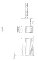
- FIG. 1A shows an example of the configuration of a frame by which a radio base station transmits data in an LTE (Long Term Evolution) system.
- LTE Long Term Evolution
- a radio base station in an LTE system, includes data in subframes and then uses a frequency in the frequency band that is assigned to its own base station to transmit these subframes in subcarrier units.
- Dividing the subframes that are transmitted by a normal radio base station and a centralized-control radio base station can be considered as a means of preventing the occurrence of interference.
- the subframes that are transmitted by a normal radio base station and the subframes that are transmitted by the centralized-control radio base station are continuous, a shift in the transmission timing of the subframes of the normal radio base station and the centralized-control radio base station results in the overlapped transmission of subframes in the same time band, whereupon interference occurs and data cannot be transmitted. Therefore, the transmission timings for transmitting subframes must be synchronized between a normal radio base station and the centralized-control radio base station.
- a problem arises in which the method of synchronizing the transmission timings between the normal radio base station and the centralized-control radio base station has not been sufficiently studied.
- a wireless communication system comprises:
- a radio base station is a radio base station that includes data in frames and uses frequencies in a predetermined frequency band to transmit the frames to a first terminal that is present in the cover area of its own base station, and comprises:
- a cooperative control method is a method by which a first radio base station cooperates with a second radio base station when the first radio base station and the second radio base station have the same area as cover area and use frequencies in the same frequency band to transmit frames included in data to a first terminal and a second terminal, respectively, the cooperative control method comprising steps of:
- a first radio base station reports to a second radio base station, that has as its cover area the same area as the first radio base station, the transmission timing at which the first radio base station transmits frames to a first terminal that is present in the cover area of the first radio base station, and the second radio base station synchronizes the transmission timing or frames that are transmitted to a second terminal with the transmission timing or frames that was reported from the first radio base station that covers the cover area in which the second terminal is present.
- reporting the transmission timing of frames of a first radio base station to a second radio base station enables the synchronization of the transmission timings of frames between the two radio base stations.
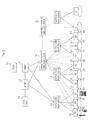
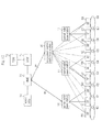
- FIG. 2 shows the configuration of the wireless communication, system of the first exemplary embodiment of the present invention.
- the wireless communication system shown in FIG. 2 includes: normal radio base stations 10-12, centralized-control radio base stations 3 0 and 31, RF transceivers 50-58, SGW (Serving Gate Way) 71, PGW (PDN Gate Way) 72, MME (Mobility Management Entity) 73, and AAA/HSS (Authentication, Authorization, Accounting/Home Subscriber Server) 74.
- Normal radio base station 10 is connected to Transceivers 50-52, covers areas 60-62, and transmits and receives data with user terminals present in cover areas 60-62. More specifically, when normal radio base station 10 transmits data to a user terminal present in cover area 60, normal radio base station 10 generates data that are to be transmitted to the user terminal and supplies the data to RF transceiver 50 and transmits the data via RF transceiver 50. In addition, data that have been transmitted from a user terminals that is present in cover area 60 are received by RF transceiver 50 and supplied to normal radio base station 10. Compared to normal radio base station 10, normal radio base stations 11 and 12 differ only in the RF transceivers that they are connected to, and detailed explanation is therefore omitted hereinbelow.
- Centralized-control radio base station 30 is connected to RF transceivers 50-58, covers areas 60-68, and transmits and receives data with machine terminals present in cover areas 60-68. Accordingly, centralized-control radio base station 30 is connected to the same RF transceivers 50-58 as normal radio base stations 10- 12, and has as cover areas the same areas as the cover areas of normal radio base stations 10-12. In addition, centralized-control radio base station 31 differs from centralized-control base station 30 only regarding the RF transceiver to which it is connected, and detailed explanation is therefore here omitted. Centralized-control radio base station 30 also transmits and receives data with machine terminals via RF transceivers with which it is connected, similar to normal radio base station 10.
- centralized-control radio base station 30 is connected to centralized-control radio base station 31 and normal radio base station 10 through X2 interfaces.
- normal radio base station 10 and centralized-control radio base station 30 are connected to SGW 71 and MME 73 through an S1 interface.
- RF transceiver 50 amplifies data that are transmitted and received between normal radio base station 10 and user terminals that are present in cover area 60 and between centralized-control radio base station 30 and machine terminals that are present in cover area 60.
- RF transceivers 51-58 have the same configuration and carry out the same operations as RF transceiver 50, and detailed explanation is therefore here omitted.
- SGW 71, PGW 72, MME 73, and AAA/HSS 74 are each devices on the core network side that perform operations such as data transfer, connection to external networks of the terminals, management of the movement of terminals, authentication of terminals and information management. Detailed explanation of these components is omitted because these components are well known to those in the field and further, and because they are not directly related to the present invention.
- FIG. 3A is a block diagram showing the configuration of normal radio base station 10.
- Normal radio base station 10 shown in FIG. 3A includes control unit 101, baseband processor 102, and time information acquisition unit 103.
- Control uni 101 controls the overall operations of normal radio base station 10 and carries out, for example, call processing as well as maintenance and monitoring processes.
- Baseband processor 102 carries out baseband processes such as decoding and encoding of data that are transmitted and received between normal radio base station 10 and RF transceiver 50.
- Time information acquisition unit 103 acquires a reference time from a GPS (Global Positioning System) or an NTP (Network Time Protocol) server, acquires time information that indicates the transmission timing of its own station based on this reference time, and supplies this time information to control unit 10 1.
- GPS Global Positioning System
- NTP Network Time Protocol
- FIG. 3B is a block diagram showing the configuration of centralized-control radio base station 30.
- Centralized-control radio base station 30 shown in FIG. include control unit 301, baseband processor 302, and time information acquisition unit 303.
- Control unit 301 controls the overall operations of centralized-control radio base station 30, and for example, carries out call processing as well as maintenance and monitoring processes.
- Baseband processor 302 carries out baseband processing of data that are transmitted and received between centralized-control radio base station 30 and RF transceiver 50.
- Time information acquisition unit 303 acquires a reference time from a GPS or NTP server, acquires time information that indicates the transmission timing of its own station based on the reference time, and supplies this time information to control unit 301.
- FIG. 3C is a block diagram showing the configuration of RF transceiver 50.
- RF transceiver 50 shown in FIG. 3C includes normal radio base station amplification unit 501 and centralized-control radio base station amplification unit 502.
- Normal radio base station amplification unit 501 amplifies data that are transmitted and received via an antenna (not shown) between normal radio base station 10 and user terminals.
- Centralized-control radio base station amplification unit 502 amplifies the data that are transmitted and received via an antenna (not shown) between centralized-control radio base station 30 and machine terminals and, through monitor interface 503, monitors data that are transmitted via normal radio base station amplification unit 501.
- normal radio base station 10 determines assignment of subframes by which centralized-control radio base station 30 includes and transmits data, and includes and transmits data in subframes other than the assigned subframes, and centralized-control radio base station 30 includes and transmits data in the subframes that were assigned.
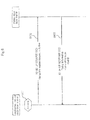
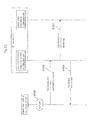
- FIG. 6 is a sequence diagram showing the operations for synchronizing transmission timings at the time of activating centralized-control radio base station 30.
- control unit 301 of centralized-control radio base station 30 transmits an X2 SETUP REQUEST message to normal radio base stations 10-12 (Step S102).
- a "Timing Information Request” IE is added to this X2 SETUP REQUEST message as a new information element, and control unit 301 sets this IE to "Active" to request time information indicating the transmission timing of frames to normal radio base stations 10-12.
- Time information acquisition unit 103 of normal radio base station 10 upon receiving the X2 SETUP REQUEST message that was transmitted from centralized-control radio base station 30, refers to the "Timing Information Request" IE, and when this IE is "active,” converts the transmission timing of its own station based on the reference time that was acquired from a GPS or NTP server to obtain timing information.
- Control unit 101 then transmits an X2 SETUP RESPONSE message, which is a response message, to centralized-control radio base station 30 (Step S103).
- a "Timing Information"" IE is added to this X2 SETUP RESPONSE message as a new information element, and control unit 101 sets the time information that was acquired by time information acquisition unit 103 and the Cell ID that is the identification information of its own station in this IE.
- Control unit 301 of centralized-control radio base station 30 upon receiving the X2 SETUP RESPONSE message that was transmitted from normal radio base stations 10-12, synchronizes the transmission timing between each normal radio base station based on the Cell ID and time information that was set in the "Timing Information" IE.
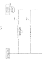
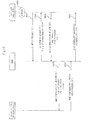
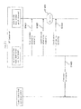
- FIG. 7 is a sequence diagram showing the operations for synchronizing the transmission timing at the time of activating normal radio base station 10.
- time information acquisition unit 103 of normal radio base station 10 acquires time information, and control unit 101 transmits an X2 SETUP REQUEST message to centralized-control radio base station 30 (Step S202).
- a "Timing Information" IE is added as a new information element to this X2 SETUP REQUEST message, and control unit 101 sets the time information that was acquired by time information acquisition unit 103 and the Cell ID in this IE.
- Control unit 301 of centralized-control radio base station 30 upon receiving the X2 SETUP REQUEST message that was transmitted from normal radio base station 10, synchronizes the transmission timing with normal radio base station 10 based on the time information that was set in the "Timing Information" IE and transmits an X2 SETUP RESPONSE message to normal radio base station 10 (Step S203).
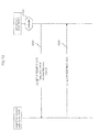
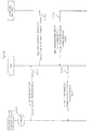
- FIG. 8 is a sequence diagram showing other operations for synchronizing the transmission timing at the time of activating normal radio base station 10.
- control unit 101 of normal radio base station 10 transmits an X2 SETUP REQUEST message to centralized-control radio base station 30 (Step S302), and control unit 301 of centralized-control radio base station 30, upon receiving the X2 SETUP REQUEST message, transmits an X2 SETUP RESPONSE message to normal radio base station 10 (Step S3 03).
- a "Timing Information Request” IE is added as a new information, element to this X2 SETUP RESPONSE message, and control unit 301 sets this IE to "active" to request time information.
- Time information acquisition unit 103 of normal radio base station 10 upon receiving the X2 SETUP RESPONSE message that was transmitted from centralized-control radio base station 30, refers to the "Timing Information Request" IE, If this IE is "Active," time information acquisition unit 103 acquires time information, and control unit 101 transmits an ENB CONFIGURATION UPDATE message to centralized-control radio base station 30 (Step S304).
- a "Timing Information” IE is added as a new information element to this ENB CONFIGURATION UPDATE message, and control unit 101 sets the time information that was acquired by time information acquisition unit 103 and the Cell ID to this IE.
- Control unit 301 of centralized-control radio base station 30 Upon receiving the ENB CONFIGURATION UPDATE message that was transmitted from normal radio base station Control unit 301 of centralized-control radio base station 30 synchronizes the transmission timing with normal radio base station 10 based on the time information that was set in the "Timing Information" IE and transmits an ENB CONFIGURATION ACKNOWLEDGE message to normal radio base station 10 (Step S305).
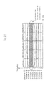
- the subframes that are assigned to centralized-control radio base station 30 must be reported to user terminals and machine terminals.
- the notification to user terminals and machine terminals is assumed to be carried out from only one radio base station of normal radio base station 10 and centralized-control radio base station 3 0, the radio base station that carries out notification being referred to as the "master base station.”
- normal radio base station 10 is assumed to be the master base station.
- subframes must be assigned each time normal radio base station 10 and centralized-control radio base station 30 are activated (or reactivated), and the operations at the time of activating each of the radio base stations are therefore described separately.
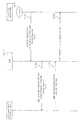
- FIG. 9 is a sequence diagram showing the operations of assigning subframes at the time of activating centralized- control radio base station 30.
- control unit 301 of centralized-control radio base station 30 transmits an X2 SETUP REQUEST message to normal radio base stations 10-12 (Step S402).
- An "Access Resource Information Request” IE is added as a new information element to this X2 SETUP REQUEST message and control unit 301 sets this IE to "Active" to request assignment of subframes.
- Control unit 101 of normal radio base station 10 upon receiving the X2 SETUP REQUEST message that was transmitted from centralized-control radio base station 30, refers to the "Access Resource Information Request” IE, and when this IE is "active,” determines the subframes that are to be assigned to centralized-control radio base station 30 and transmits an X2 SETUP RESPONSE message to centralized-control radio base station 30 (Step S403).
- An "Access Resource Information” IE is added as a new information element to this X2 SETUP RESPONSE message, and control unit 101 sets the Subframe numbers of the assigned subframes and Cell ID in this IE.
- Control unit 101 of normal radio base station 10 transmits an RRC: System Information message that is notification information that includes the Subframe numbers to report the Subframe numbers of the assigned subframes to user terminals and machine terminals that are present in cover areas 60-62. More specifically, a "centralized-control radio base station SubframeConfig" IE is added as a new information element to a System Information Block Type 2 message, and normal radio base station 10 sets the Subframe numbers of the assigned subframes in this IE.
- control unit 301 of centralized-control radio base station 30 When control unit 301 of centralized-control radio base station 30 receives the X2 SETUP RESPONSE message that was transmitted from normal radio base stations 10-12 and when the Cell ID that is set in the "Access Resource Information" IE indicates, for example, normal radio base station 10, control unit 301 includes data in the subframes that were assigned from normal radio base station 10 and transmits the subframes to machine terminals that are present in cover areas 60-62.
- the transmission timings are synchronized between normal radio base station 10 and centralized-control radio base station 30 as described hereinabove, and centralized-control radio base station 30 is able to find the timing of transmitting subframes that were assigned to it from these transmission timings, whereby the radio base stations that transmit data at the timings of the start and end of the assigned subframes can be switched and the occurrence of interference can be prevented.
- FIG. 10 is a sequence diagram showing the operations of assigning subframes at the time of activating normal radio base station 10.
- control unit 101 of normal radio base station 10 determines the subframes that are to be assigned to centralized-control radio base station 30, and transmits an X2 SETUP REQUEST message to centralized-control radio base station 30 (Step S502.).
- An "Access Resource Information" IE is added as a new information element to this X2 SETUP REQUEST message, and control unit 101 sets the Cell ID and the Subframe numbers of the assigned subframes in this IE.
- control unit 101 includes the Subframe numbers of the assigned subframes in an RRC: System Information message and transmits the message.
- control unit 301 of centralized-control radio base station 30 Upon receiving the X2 SETUP REQUEST message that was transmitted from normal radio base station 10, control unit 301 of centralized-control radio base station 30 transmits an X2 SETUP RESPONSE message to normal radio base station 10 (Step S503) and includes data in subframes that were assigned from normal radio base station 10 and transmits to machine terminals present in cover areas 60-62.
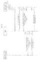
- FIG. 11 is a sequence diagram showing other operations of assigning subframes at the time of activating normal radio base station 10.
- control unit 101 of normal radio base station 10 transmits an X2 SETUP REQUEST message to centralized-control radio base station 30 (Step S602), and control unit 301 of centralized-control radio base station 30, upon receiving this X2 SEPUP REQUEST message, transmits an X2 SETUP RESPONSE message to normal radio base station 10 (Step S603).
- An "Access Resource Information Request” IE is added as a new information element to this X2 SETUP RESPONSE message, and control unit 301 sets this IE to "Active" to request assignment of subframes.
- control unit 101 of normal radio base station 10 Upon receiving the X2 SETUP RESPONSE message that was transmitted from centralized-control radio base station 30, control unit 101 of normal radio base station 10 refers to the "Access Resource Information Bequest” IE, and when this IE is "active,” determines the subframes that are to be assigned to centralized-control radio base station 30 and transmits an ENB CONFIGURATION UPDATE message to centralized-control radio base station 30 (Step S604).
- An "Access Resource Information” IE is added as a new information element to this END CONFIGURATION UPDATE message, and control unit 101 sets the Cell ID and Subframe numbers of assigned subframes in this IE.
- control unit 101 includes the Subframe numbers of subframes that were assigned in an RRC: System Information message and transmits the message.
- control unit 301 ofcentralized-control radio base station 30 Upon receiving the ENB CONFIGURATION UPDATE message that was transmitted from normal radio base station 10, control unit 301 ofcentralized-control radio base station 30 transmits an ENB CONFIGURATION ACKNOWLEDGE message to normal radio base station 10 (Step S605) and includes data in subframes assigned from normal radio base station 10 and transmits the subframes to machine terminals present in cover areas 60-62.
- normal radio base station. 10 transmits to centralized-control radio base station 30 time information that indicates the transmission timings of frames, and centralized-control radio base station 30 synchronizes the transmission timings with normal radio base station 10 based on this time information and transmits data in the subframes assigned from normal radio base station 10.
- normal radio base station 10 further transmits to user terminals and machine terminals notification information that indicates subframes that are assigned to centralized-control radio base station 30.
- the notification information directed to user terminals and the notification information directed to machine terminals can be unified and each of the terminals can smoothly connect to a radio base station.
- the present exemplary embodiment differs from the first exemplary embodiment in that normal radio base station 10 and centralized-control radio base station 30 communicate information via MME 73 through an S1 interface.
- FIG. 13 is a sequence diagram showing the operations for synchronizing the transmission timings at the time of activating centralized-control radio base station 30.
- control unit 301 of centralized-control radio base station 30 transmits an S1 SETUP REQUEST message to MME 73 (Step S702).
- a "Timing Information Request” IE is added as a new information element to this S1 SETUP REQUEST message, and control unit 301 sets the IE to "Active" to request time information.
- MME 73 Upon receiving the S1 SETUP REQUEST message that is transmitted from centralized-control radio base station 30, MME 73 refers to the "Timing Information Request” IE, and when this IE is "Active,” transmits an MME CONFIGURATION UPDATE message to normal radio base stations 10-12 (Step S703).
- a "Timing Information Request” IE is added as a new information element to this MME CONFIGURATION UPDATE message, and MME 73 sets the IE to "active.”
- time information acquisition unit 103 of normal radio base station 10 Upon receiving the MME CONFIGURATION UPDATE message that is transmitted from MME 73, time information acquisition unit 103 of normal radio base station 10 refers to the "Timing Information Request" IE, and acquires the time information if this IE is "active," and control unit 101 transmits an MME CONFIGURATION UPDATE ACKNOWLEDGE message to MME 73 (Step S704).
- a "Timing Information” IE is added as a new information, element to this MME CONFIGURATION UPDATE ACKNOWLEDGE message, and control unit 101 sets the Cell ID and time information that was acquired by time information acquisition unit 103 in this IE.
- MME 73 Upon receiving the MME CONFIGURATION ACKNOWLEDGE message that is transmitted from normal radio base station 10, MME 73 transmits an S1 SETUP RESPONSE message to centralized-control radio base station 30 (Step S705).
- a "Timing Information" TIE is added as a new information element to this S1 SETUP RESPONSE message, and MME 73 sets in this IE the Cell ID and time information that were set in the "Timing Information" IE of then MME CONFIGURATION ACKNOWLEDGE message.
- control unit 301 of centralized-control radio base station 30 Upon receiving the S1 SETUP RESPONSE message that is transmitted from MME 73, control unit 301 of centralized-control radio base station 30 synchronizes the transmission timings with each of the normal radio base stations based on the Cell ID and time information that were set in the "Timing Information" IE.
- FIG. 14 is a sequence diagram showing the operations for synchronizing the transmission timings at the time of activating normal radio base station 10.
- time information acquisition unit 103 of normal radio base station 10 acquires time information, and control unit 101 transmits an S1 SETUP REQUEST message to MME 73 (Step S802).
- a "Timing Information" IE is added as a new information element to this S1 SETUP REQUEST message, and control unit 101 sets the time information and Cell ID that were acquired by time information acquisition unit 103 in this IE.
- MME 73 Upon receiving the S1 SETUP REQUEST message that was transmitted from normal radio base station 10, MME 73 transmits a MME CONFIGURATION UPDATE message to centralized-control radio base station 30 (Step S803).
- a "Timing Information" IE is added as a new information element to this MME CONFIGURATION UPDATE message, and MME 73 sets in this IE the time information and Cell ID that were set in the "Timing Information" IE of the S1 SETUP REQUEST message.
- control unit 301 of centralized-control radio base station 30 synchronizes the transmission timing with normal radio base station 10 based on the time information that was set in the "Timing Information" IE.
- control unit 301 transmits to MME 73 a MME CONFIGURATION UPDATE ACKNOWLEDGE message (Step S804), and upon receiving this MME CONFIGURATION UPDATE ACKNOWLEDGE message, MME 73 transmits an S SETUP RESPONSE message to normal radio base station 10 (Step S805).
- C-3) Other operations at the time of activating normal radio base station 10:
- FIG. 15 is a sequence diagram showing other Operations for synchronizing the transmission timing at the time of activating normal radio base station 10.
- control unit 10 of normal radio base station 10 transmits an S1 SETUP REQUEST message to MME 73 (Step S902), and upon receiving this S1 SETUP REQUEST message, MME 73 transmits an S1 SETUP RESPONSE message to normal radio base station 10 (Step S903).
- a "Timing Information Request” IE is added as a new information element to this S1 SETUP RESPONSE message, and MME 73 sets this IE to "Active" to request time information.
- time information acquisition unit 103 of normal radio base station 10 Upon receiving the S1 SETUP RESPONSE message that is transmitted from MME 73, time information acquisition unit 103 of normal radio base station 10 refers to the "Timing Information Request" IE and acquires time information if this IE is "Active," and control unit 101 transmits an ENB CONFIGURATION UPDATE message to MME 73 (Step S904).
- a "Timing Information” IE is added as a new information element to this ENB CONFIGURATION UPDATE message, and control unit 101 sets in this IE the Cell And time information acquired by time information acquisition unit 103.
- Steps S803 and S804 Processes similar to Steps S803 and S804 are then carried out, and control unit 301 of centralized-control radio base station 30 synchronizes the transmission timing with normal radio base station 10.
- MME 73 Upon receiving the MME CONFIGURATION UPDATE ACKNOWLEDGE message that is transmitted from centralized-control radio base station 30, MME 73 transmits an ENB CONFIGURATION ACKNOWLEDGE message to normal radio base station 10 (Step S905).
- FIG. 16 is a sequence diagram showing the operations for assigning subframes at the time of activating of centralized-control radio base station 30.
- control unit 301 of centralized-control radio base station 30 transmits an S1 SETUP REQUEST message to MME 73 (Step S1002).
- An "access Resource Information Request” IE is added as a new information element to this S1 SETUP REQUEST message, and control unit 301 sets this IE to "Active" to request assignment of subframes.
- MME 73 Upon receiving the S1 SETUP REQUEST message that is transmitted from centralized-control radio base station 30, MME 73 refers to the "Access Resource Information Request” IE and if this IE is "active,” transmits an MME CONFIGURATION UPDATE message to normal radio base stations 10-12 (Step S1003). An "Access Resource Information Request” IE is added as a new information element to this MME CONFIGURATION UPDATE message, and MME 73 sets this IE to "active.”
- control unit 101 of normal radio base station 10 Upon receiving the MME CONFIGURATION UPDATE message that is transmitted from MME 73, control unit 101 of normal radio base station 10 refers to the "Access Resource Information Request" IE, and if this IE is "Active,” determines the subframes that are to be assigned to centralized-control radio base station 30 and transmits an MME CONFIGURATION UPDATE ACKNOWLEDGE message to MME 73 (Step S1004).
- An "Access Resource Information” IE is added as a new information element to this MME CONFIGURATION UPDATE ACKNOWLEDGE message, and control unit 101 sets in this IE the Cell ID and the Subframe numbers of the subframes that were assigned.
- control unit 101 includes the Subframe numbers of the subframes that were assigned in an RRC: System Information message and transmits the message.
- MME 73 Upon receiving the MME CONFIGURATION UPDATE ACKNOWLEDGE message that is transmitted from normal radio base station 10, MME 73 transmits an S SETUP RESPONSE message to centralized-control radio base station 30 (Step S1005).
- An "Access Resource Information” IE is added as a new information element to this S1 SETUP RESPONSE message, and MME 73 sets in this IE the Cell ID and Subframe numbers that were set in the "Access Resource Information" IE of the MME CONFIGURATION ACKNOWLEDGE message.
- control unit 301 of centralized-control radio base station 30 When control unit 301 of centralized-control radio base station 30 receives the S1 SETUP RESPONSE message that was transmitted from MME 73 and the Cell ID that is set in the "Access Resource Information" IE indicates, for example, normal radio base station 10, control unit 30 includes data in the subframes that were assigned from normal radio base station 10 and transmits the subframes to machine terminals present in cover areas 60-62.
- FIG. 17 is a sequence diagram showing the operations of assigning subframes at the time of activating normal radio base station 10.
- control unit 101 of normal radio base station 10 determines subframes that are to be assigned to centralized-control radio base station 30 and transmits an S1 SETUP REQUEST message to MME 73 (Step S1102).
- An "Access Resource Information" IE is added as a new information element to this S1 SETUP REQUEST message, and control unit 101 sets the Cell ID and Subframe numbers of the assigned subframes in this IE,
- Control unit 101 of normal radio base station 10 further includes the Subframe numbers of the assigned subframes in an RRC: System Information message and transmits the message.
- MME 73 Upon receiving the S1 SETUP REQUEST message that is transmitted from normal radio base station 10, MME 73 transmits an MME CONFIGURATION UPDATE message to centralized-control radio base station 30 (Step S1103).
- An "Access Resource Information” IE is added as a new information element to this MME CONFIGURATION UPDATE message, and MME 73 sets the Subframe numbers and Cell ID that were set in the "Access Resource Information"" IE of the S1 SETUP REQUEST message in this IE.
- control unit 301 of centralized-control radio base station 30 Upon receiving the MME CONFIGURATION UPDATE message that is transmitted from MME 73, control unit 301 of centralized-control radio base station 30 transmits an MME CONFIGURATION UPDATE ACKNOWLEDGE message to MME 73 (Step S1104) and includes data in the subframes that were assigned from normal radio base station 10 and transmits the subframes to machine terminals that are present in cover areas 60-62.
- MME 73 Upon receiving the MME CONFIGURATION UPDATE ACKNOWLEDGE message that was transmitted from centralized-control radio base station 30, MME 73 transmits an S1 SETUP RESPONSE message to normal radio base station 10 (Step S1105).
- FIG. 18 is a sequence diagram showing other operations of assigning subframes at the time of activating normal radio base station 10.
- control unit 101 of normal radio base station 10 transmits an S1 SETUP REQUEST message to MME 73 (Step S1202), and upon receiving the S1 SETUP REQUEST message that is transmitted from normal radio base station, MME 73 transmits an S1 SETUP RESPONSE message to normal radio base station 10 (Step S1203).
- An "Access Resource Information Bequest” IE is added as a new information, element to this S1 SETUP REQUEST message, and MME 73 sets this IE to "Active" to request the assignment of subframes.
- control unit 101 of normal radio base station 10 Upon receiving the S1 SETUP RESPONSE message that is transmitted from MME 73, control unit 101 of normal radio base station 10 refers to "Access Resource Information Request" IE, and if the IE is "Active,” determines the subframes that are to be assigned to centralized-control radio base station 30 and transmits an ENB CONFIGURATION UPDATE message to MME 73 (Step S1204).
- An "Access Resource Information” IE is added as a new information element to this END CONFIGURATION UPDATE message, and control unit 101 sets the Subframe numbers of the assigned subframes and Cell ID in this IE.
- MME 73 Upon receiving the ENB CONFIGURATION UPDATE message that is transmitted from normal radio base station 10, MME 73 transmits an MME CONFIGURATION UPDATE message to centralized-control radio base station 30 (Step S1205).
- An "Access Resource Information" IE is added as a new information element to this MME CONFIGURATION UPDATE message, and MME 73 sets in this IE the Cell ID and Subframe numbers that were set in the "Access Resource Information" IE of the ENB CONFIGURATION UPDATE message.
- control unit 301 of centralized-control radio base station 30 Upon receiving the MME CONFIGURATION UPDATE message that is transmitted from MME 73, control unit 301 of centralized-control radio base station 30 transmits an MME CONFIGURATION UPDATE ACKNOWLEDGE message to MME 73 (Step S1206) and includes data in subframes that were assigned from normal radio base station 10 and transmits the subframes to machine terminals that are present in cover areas 60-62.
- MME 73 Upon receiving the MME CONFIGURATION UPDATE ACKNOWLEDGE message that is transmitted from centralized-control radio base station 30, MME 73 transmits an ENB CONFIGURATION ACKNOWLEDGE message to normal radio base station 10 (Step S1207).
- normal radio base station 10 and centralized-control radio base station 30 communicate information via MME 73 that is a higher-order device.
- the transmission timing between normal radio base station 10 and centralized-control radio base station 30 can be synchronized and subframes can be assigned without communicating information through an X2 interface.
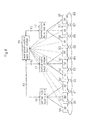
- the present exemplary embodiment differs from the first and second exemplary embodiments in that normal radio base station 10 and centralized-control radio base station 30 communicate information via RF transceiver 50 that is connected in common, as shown in FIG. 19 .
- normal radio base station 10 and centralized-control radio base station 30 are described as being connected to only one RF transceiver 50 in FIG. 19 .
- the configurations of normal radio base station 10, centralized-control radio base station 30, and transceiver 50 are identical to those in the first and second exemplary embodiments and detailed explanation is therefore omitted.
- FIG. 20 is a sequence diagram showing the operations for synchronizing the transmission timing at the time of activating centralized-control radio base station 30.
- Control unit 101 of normal radio base station 10 transmits synchronization information (time information) indicating the transmission timing to user terminals present in cover areas 60-62 via normal radio base station amplification unit 501 by a Synchronization Channel.
- control unit 301 of centralized-control radio base station 30 provisionally determines the transmission timing and communicates the provisionally determined transmission timing to centralized-control radio base station amplification unit 502 and transmits a synchronization information confirmation request requesting correction information indicating the amount of correction of the provisionally determined transmission timing (Step S1302).
- centralized-control radio base station amplification unit 502 of RF transceiver 50 monitors the synchronization information that is transmitted via normal radio base station amplification unit 501 (Step S1303).
- Centralized-control radio base station amplification unit 502 further, based on the synchronization information that was monitored, calculates the correction amount of the transmission timing that was reported from centralized-control radio base station 30 such that the transmission timings are synchronized between normal radio base station 10 and centralized-control radio base station 30 and supplies correction amount information that indicates the calculated correction amount to centralized-control radio base station 30 (Step S1304).
- Control unit 301 of centralized-control radio base station 30 corrects the transmission timing that was provisionally determined based on the correction information that was supplied from RF transceiver 50.
- FIG. 21 is a sequence diagram showing the operations for synchronizing the transmission timing at the time of activating normal radio base station 10.
- Centralized-control radio base station amplification unit 502 of RF transceiver 50 constantly monitors the synchronization information that is transmitted via normal radio base station amplification unit 501 (Steps S1401 and S1402). Normal radio base station 300 is not activated in Steps S1401 and S1402 and does not transmit synchronization information.
- Step S1403 When normal radio base station 10 is activated (Step S1403) and begins transmission of synchronization information via normal radio base station amplification unit 501, centralized-control radio base station amplification unit 502 monitors the synchronization information (Step S1404), calculates the correction amount of the transmission timing that was communicated from centralized-control radio base station 30 based on the synchronization information that was monitored and supplies the correction information to centralized-control radio base station 30 (StepS 1405).
- Control unit 301 of centralized-control radio base station 30 corrects the transmission timing that was provisionally determined based on the correction information that was supplied from RF transceiver 50.
- centralized-control radio base station 30 synchronizes the transmission timing with normal radio base station 10 based on the transmission timing of normal radio base station 10 that was communicated from RF transceiver 50.
- the transmission timing between normal radio base station 10 and centralized-control radio base station 30 can be synchronized without reporting the information that is necessary for synchronizing transmission timing through an X2 interface or an S I interface.
- the present invention is not limited to this form, and the transmission timing of normal radio base station 10 that is indicated by synchronization information may be reported to centralized-control radio base station 30 and centralized -control radio base station 30 may then synchronize the transmission timing with normal radio base station 10 based on this report.
- normal radio base station 10 reports to centralized-control radio base station 30 subframes that were assigned and transmits data to user terminals by subcarriers other than the assigned subcarriers, and centralized-control radio base station 30 transmits data to machine terminals in subcarriers that are assigned from normal radio base station 10.
Landscapes
- Engineering & Computer Science (AREA)
- Computer Networks & Wireless Communication (AREA)
- Signal Processing (AREA)
- Mobile Radio Communication Systems (AREA)
Applications Claiming Priority (2)
| Application Number | Priority Date | Filing Date | Title |
|---|---|---|---|
| JP2010023120 | 2010-02-04 | ||
| PCT/JP2010/073152 WO2011096147A1 (fr) | 2010-02-04 | 2010-12-22 | Système de communication sans fil, station de base radio et procédé de commande coopérative |
Publications (1)
| Publication Number | Publication Date |
|---|---|
| EP2533584A1 true EP2533584A1 (fr) | 2012-12-12 |
Family
ID=44355169
Family Applications (1)
| Application Number | Title | Priority Date | Filing Date |
|---|---|---|---|
| EP10845278A Withdrawn EP2533584A1 (fr) | 2010-02-04 | 2010-12-22 | Système de communication sans fil, station de base radio et procédé de commande coopérative |
Country Status (5)
| Country | Link |
|---|---|
| US (1) | US20120294243A1 (fr) |
| EP (1) | EP2533584A1 (fr) |
| JP (1) | JP5464217B2 (fr) |
| CN (1) | CN102754497A (fr) |
| WO (1) | WO2011096147A1 (fr) |
Cited By (1)
| Publication number | Priority date | Publication date | Assignee | Title |
|---|---|---|---|---|
| EP3091804A4 (fr) * | 2013-12-31 | 2017-04-12 | ZTE Corporation | Procédé et dispositif pour un traitement d'informations |
Families Citing this family (2)
| Publication number | Priority date | Publication date | Assignee | Title |
|---|---|---|---|---|
| US9179397B2 (en) * | 2012-08-22 | 2015-11-03 | Qualcomm Incorporated | Wireless local area network discovery using non-WLAN timing reference |
| CN103019172B (zh) * | 2012-11-06 | 2017-10-13 | 西华大学 | 自组织无线电监测系统 |
Family Cites Families (13)
| Publication number | Priority date | Publication date | Assignee | Title |
|---|---|---|---|---|
| JPH08198415A (ja) | 1995-01-26 | 1996-08-06 | Nippon Denki Ido Tsushin Kk | 在庫管理システム |
| JP3306843B2 (ja) * | 1996-02-05 | 2002-07-24 | 日本電信電話株式会社 | マイクロセルを用いた移動通信方法 |
| JP2001189961A (ja) * | 1999-12-28 | 2001-07-10 | Matsushita Electric Ind Co Ltd | 無線装置 |
| US6947768B2 (en) * | 2001-09-28 | 2005-09-20 | Kabushiki Kaisha Toshiba | Base station apparatus and terminal apparatus |
| JP5054422B2 (ja) * | 2007-04-27 | 2012-10-24 | 株式会社エヌ・ティ・ティ・ドコモ | 移動通信システム、基地局装置、移動局装置、および、スケジューリング方法 |
| EP2324673A1 (fr) * | 2008-07-01 | 2011-05-25 | Nokia Siemens Networks Oy | Décalage de préambule pour stations de base femto |
| JP2010023120A (ja) | 2008-07-15 | 2010-02-04 | Ihi Corp | ロボットハンドとこれを用いた対象物の把持方法 |
| US8774084B2 (en) * | 2008-08-22 | 2014-07-08 | Qualcomm Incorporated | Base station synchronization |
| KR20100038558A (ko) * | 2008-10-06 | 2010-04-15 | 삼성전자주식회사 | 계층적 셀 구조를 갖는 무선통신 시스템에서 간섭 제어 방법 및 장치 |
| US8774230B2 (en) * | 2009-04-08 | 2014-07-08 | Qualcomm Incorporated | Conveying synchronization stratum information |
| WO2010150952A1 (fr) * | 2009-06-23 | 2010-12-29 | Lg Electronics Inc. | Procédé de transmission d'information d'ordonnancement dans un système de communications mobiles, et appareil de station de base de femtocellule l'utilisant |
| US9544913B2 (en) * | 2009-08-24 | 2017-01-10 | Fraunhofer Gesellschaft Zur Forderung Der Angewandten Forschung E.V. | Controlling scheduling decisions in a distributed cooperation system |
| EP2508033B1 (fr) * | 2009-11-30 | 2014-08-13 | Telefonaktiebolaget L M Ericsson (publ) | Limitation d'interférence en communication de signal de liaison descendante à un terminal mobile |
-
2010
- 2010-12-22 CN CN2010800632425A patent/CN102754497A/zh active Pending
- 2010-12-22 EP EP10845278A patent/EP2533584A1/fr not_active Withdrawn
- 2010-12-22 JP JP2011552670A patent/JP5464217B2/ja not_active Expired - Fee Related
- 2010-12-22 WO PCT/JP2010/073152 patent/WO2011096147A1/fr active Application Filing
- 2010-12-22 US US13/577,187 patent/US20120294243A1/en not_active Abandoned
Non-Patent Citations (1)
| Title |
|---|
| See references of WO2011096147A1 * |
Cited By (2)
| Publication number | Priority date | Publication date | Assignee | Title |
|---|---|---|---|---|
| EP3091804A4 (fr) * | 2013-12-31 | 2017-04-12 | ZTE Corporation | Procédé et dispositif pour un traitement d'informations |
| US10321322B2 (en) | 2013-12-31 | 2019-06-11 | Zte Corporation | Method and device for processing information |
Also Published As
| Publication number | Publication date |
|---|---|
| JP5464217B2 (ja) | 2014-04-09 |
| US20120294243A1 (en) | 2012-11-22 |
| WO2011096147A1 (fr) | 2011-08-11 |
| JPWO2011096147A1 (ja) | 2013-06-10 |
| CN102754497A (zh) | 2012-10-24 |
Similar Documents
| Publication | Publication Date | Title |
|---|---|---|
| CN110547031B (zh) | 通信装置、基站装置、方法和记录介质 | |
| KR101828876B1 (ko) | 무선 통신 방법, 무선 통신 시스템, 무선 기지국 및 무선 단말기 | |
| US20230261829A1 (en) | Wireless communication method and apparatus, device, and storage medium | |
| US11172539B2 (en) | Base station and terminal device | |
| EP3119149B1 (fr) | Procédé de traitement de communications et dispositif d'enb | |
| EP2810530B1 (fr) | Dispositif de communication mobile, controleur de réseau et procédé pour fournir la capacité relais niveau-réseau d'un equipment utilisateur | |
| US10405168B2 (en) | Public safety system | |
| CN102668677A (zh) | 用于在无线电接入网络中进行承载建立的方法 | |
| CN111278135A (zh) | 信号传输方法和设备 | |
| US20150111574A1 (en) | Relay device, wireless terminal device, communication system and communication method | |
| CN109155950A (zh) | 电子设备及由电子设备执行的方法 | |
| CN110495203B (zh) | 共存干扰上报方法及装置、移动终端及存储介质 | |
| US9485644B2 (en) | Base station device, wireless communication system, and method of controlling base station device | |
| US20190380088A1 (en) | Terminal device, base station, control device, method, and recording medium | |
| JPWO2018193496A1 (ja) | 無線端末、基地局、無線通信システム及び無線通信方法 | |
| CN112840713B (zh) | 无线通信方法及装置、终端及存储介质 | |
| EP2533584A1 (fr) | Système de communication sans fil, station de base radio et procédé de commande coopérative | |
| US8385905B2 (en) | System and method for cell information broadcasting in reduced-size local environments in a cellular mobile communication system | |
| EP2566254B1 (fr) | Système de communication sans fil, appareil de station de base radio, appareil de réseau de noyau et procédé de communication de données | |
| EP2612529B1 (fr) | Procédés permettant de coordonner un balayage de canaux entre des stations de base dans un système de radiocommunication à ressources non partagées | |
| US20130143582A1 (en) | Transmitting radio configuration parameters from a base station to a relay node | |
| EP3247171B1 (fr) | Système de communication sans fil, station de commande et terminal | |
| US10129913B2 (en) | Method and system for direct communication between mobile terminals | |
| CN113519192A (zh) | 数据传输方法、装置和通信设备 | |
| WO2011070644A1 (fr) | Système de communication mobile, appareil de station de base, appareil de station mobile et procédé de commande de puissance d'appareil de station de base |
Legal Events
| Date | Code | Title | Description |
|---|---|---|---|
| PUAI | Public reference made under article 153(3) epc to a published international application that has entered the european phase |
Free format text: ORIGINAL CODE: 0009012 |
|
| 17P | Request for examination filed |
Effective date: 20120822 |
|
| AK | Designated contracting states |
Kind code of ref document: A1 Designated state(s): AL AT BE BG CH CY CZ DE DK EE ES FI FR GB GR HR HU IE IS IT LI LT LU LV MC MK MT NL NO PL PT RO RS SE SI SK SM TR |
|
| DAX | Request for extension of the european patent (deleted) | ||
| STAA | Information on the status of an ep patent application or granted ep patent |
Free format text: STATUS: THE APPLICATION HAS BEEN WITHDRAWN |
|
| 18W | Application withdrawn |
Effective date: 20160621 |