EP2533262B1 - Elektromagnetisches Relais und Herstellungsverfahren dafür - Google Patents
Elektromagnetisches Relais und Herstellungsverfahren dafür Download PDFInfo
- Publication number
- EP2533262B1 EP2533262B1 EP12165724.1A EP12165724A EP2533262B1 EP 2533262 B1 EP2533262 B1 EP 2533262B1 EP 12165724 A EP12165724 A EP 12165724A EP 2533262 B1 EP2533262 B1 EP 2533262B1
- Authority
- EP
- European Patent Office
- Prior art keywords
- movable
- fixed
- contact
- fixed contact
- movable contact
- Prior art date
- Legal status (The legal status is an assumption and is not a legal conclusion. Google has not performed a legal analysis and makes no representation as to the accuracy of the status listed.)
- Not-in-force
Links
- 238000004519 manufacturing process Methods 0.000 title claims description 12
- 230000004907 flux Effects 0.000 claims description 7
- 239000000696 magnetic material Substances 0.000 claims description 6
- 239000002184 metal Substances 0.000 claims 2
- 239000011347 resin Substances 0.000 description 10
- 229920005989 resin Polymers 0.000 description 10
- 239000000463 material Substances 0.000 description 9
- 230000001965 increasing effect Effects 0.000 description 7
- 239000011810 insulating material Substances 0.000 description 6
- XEEYBQQBJWHFJM-UHFFFAOYSA-N Iron Chemical compound [Fe] XEEYBQQBJWHFJM-UHFFFAOYSA-N 0.000 description 5
- 238000005452 bending Methods 0.000 description 5
- 239000000428 dust Substances 0.000 description 4
- 238000004080 punching Methods 0.000 description 4
- PXHVJJICTQNCMI-UHFFFAOYSA-N Nickel Chemical compound [Ni] PXHVJJICTQNCMI-UHFFFAOYSA-N 0.000 description 3
- 238000013459 approach Methods 0.000 description 3
- 229910052742 iron Inorganic materials 0.000 description 3
- 238000002844 melting Methods 0.000 description 3
- 230000008018 melting Effects 0.000 description 3
- VYPSYNLAJGMNEJ-UHFFFAOYSA-N Silicium dioxide Chemical compound O=[Si]=O VYPSYNLAJGMNEJ-UHFFFAOYSA-N 0.000 description 2
- 239000007769 metal material Substances 0.000 description 2
- 229910052759 nickel Inorganic materials 0.000 description 2
- 230000003014 reinforcing effect Effects 0.000 description 2
- 229910000938 samarium–cobalt magnet Inorganic materials 0.000 description 2
- YCKRFDGAMUMZLT-UHFFFAOYSA-N Fluorine atom Chemical compound [F] YCKRFDGAMUMZLT-UHFFFAOYSA-N 0.000 description 1
- 239000000919 ceramic Substances 0.000 description 1
- 239000011248 coating agent Substances 0.000 description 1
- 238000000576 coating method Methods 0.000 description 1
- 239000010941 cobalt Substances 0.000 description 1
- 229910017052 cobalt Inorganic materials 0.000 description 1
- GUTLYIVDDKVIGB-UHFFFAOYSA-N cobalt atom Chemical compound [Co] GUTLYIVDDKVIGB-UHFFFAOYSA-N 0.000 description 1
- PMHQVHHXPFUNSP-UHFFFAOYSA-M copper(1+);methylsulfanylmethane;bromide Chemical compound Br[Cu].CSC PMHQVHHXPFUNSP-UHFFFAOYSA-M 0.000 description 1
- 230000001419 dependent effect Effects 0.000 description 1
- 230000002708 enhancing effect Effects 0.000 description 1
- 239000011737 fluorine Substances 0.000 description 1
- 229910052731 fluorine Inorganic materials 0.000 description 1
- 230000007257 malfunction Effects 0.000 description 1
- 238000000034 method Methods 0.000 description 1
- 238000000465 moulding Methods 0.000 description 1
- 229910001172 neodymium magnet Inorganic materials 0.000 description 1
- TWNQGVIAIRXVLR-UHFFFAOYSA-N oxo(oxoalumanyloxy)alumane Chemical compound O=[Al]O[Al]=O TWNQGVIAIRXVLR-UHFFFAOYSA-N 0.000 description 1
- 229920000052 poly(p-xylylene) Polymers 0.000 description 1
- 229910052814 silicon oxide Inorganic materials 0.000 description 1
- 229910000859 α-Fe Inorganic materials 0.000 description 1
Images


Classifications
-
- H—ELECTRICITY
- H01—ELECTRIC ELEMENTS
- H01H—ELECTRIC SWITCHES; RELAYS; SELECTORS; EMERGENCY PROTECTIVE DEVICES
- H01H51/00—Electromagnetic relays
- H01H51/02—Non-polarised relays
- H01H51/04—Non-polarised relays with single armature; with single set of ganged armatures
- H01H51/06—Armature is movable between two limit positions of rest and is moved in one direction due to energisation of an electromagnet and after the electromagnet is de-energised is returned by energy stored during the movement in the first direction, e.g. by using a spring, by using a permanent magnet, by gravity
-
- H—ELECTRICITY
- H01—ELECTRIC ELEMENTS
- H01H—ELECTRIC SWITCHES; RELAYS; SELECTORS; EMERGENCY PROTECTIVE DEVICES
- H01H50/00—Details of electromagnetic relays
- H01H50/54—Contact arrangements
-
- H—ELECTRICITY
- H01—ELECTRIC ELEMENTS
- H01H—ELECTRIC SWITCHES; RELAYS; SELECTORS; EMERGENCY PROTECTIVE DEVICES
- H01H50/00—Details of electromagnetic relays
- H01H50/16—Magnetic circuit arrangements
- H01H50/36—Stationary parts of magnetic circuit, e.g. yoke
- H01H50/38—Part of main magnetic circuit shaped to suppress arcing between the contacts of the relay
-
- H—ELECTRICITY
- H01—ELECTRIC ELEMENTS
- H01H—ELECTRIC SWITCHES; RELAYS; SELECTORS; EMERGENCY PROTECTIVE DEVICES
- H01H50/00—Details of electromagnetic relays
- H01H50/54—Contact arrangements
- H01H50/56—Contact spring sets
-
- H—ELECTRICITY
- H01—ELECTRIC ELEMENTS
- H01H—ELECTRIC SWITCHES; RELAYS; SELECTORS; EMERGENCY PROTECTIVE DEVICES
- H01H50/00—Details of electromagnetic relays
- H01H50/02—Bases; Casings; Covers
- H01H50/04—Mounting complete relay or separate parts of relay on a base or inside a case
- H01H50/047—Details concerning mounting a relays
-
- H—ELECTRICITY
- H01—ELECTRIC ELEMENTS
- H01H—ELECTRIC SWITCHES; RELAYS; SELECTORS; EMERGENCY PROTECTIVE DEVICES
- H01H50/00—Details of electromagnetic relays
- H01H50/16—Magnetic circuit arrangements
- H01H50/18—Movable parts of magnetic circuits, e.g. armature
- H01H50/24—Parts rotatable or rockable outside coil
- H01H50/28—Parts movable due to bending of a blade spring or reed
-
- H—ELECTRICITY
- H01—ELECTRIC ELEMENTS
- H01H—ELECTRIC SWITCHES; RELAYS; SELECTORS; EMERGENCY PROTECTIVE DEVICES
- H01H9/00—Details of switching devices, not covered by groups H01H1/00 - H01H7/00
- H01H9/30—Means for extinguishing or preventing arc between current-carrying parts
- H01H9/34—Stationary parts for restricting or subdividing the arc, e.g. barrier plate
-
- H—ELECTRICITY
- H01—ELECTRIC ELEMENTS
- H01H—ELECTRIC SWITCHES; RELAYS; SELECTORS; EMERGENCY PROTECTIVE DEVICES
- H01H9/00—Details of switching devices, not covered by groups H01H1/00 - H01H7/00
- H01H9/30—Means for extinguishing or preventing arc between current-carrying parts
- H01H9/44—Means for extinguishing or preventing arc between current-carrying parts using blow-out magnet
- H01H9/443—Means for extinguishing or preventing arc between current-carrying parts using blow-out magnet using permanent magnets
-
- H—ELECTRICITY
- H01—ELECTRIC ELEMENTS
- H01H—ELECTRIC SWITCHES; RELAYS; SELECTORS; EMERGENCY PROTECTIVE DEVICES
- H01H9/00—Details of switching devices, not covered by groups H01H1/00 - H01H7/00
- H01H9/30—Means for extinguishing or preventing arc between current-carrying parts
- H01H9/46—Means for extinguishing or preventing arc between current-carrying parts using arcing horns
-
- Y—GENERAL TAGGING OF NEW TECHNOLOGICAL DEVELOPMENTS; GENERAL TAGGING OF CROSS-SECTIONAL TECHNOLOGIES SPANNING OVER SEVERAL SECTIONS OF THE IPC; TECHNICAL SUBJECTS COVERED BY FORMER USPC CROSS-REFERENCE ART COLLECTIONS [XRACs] AND DIGESTS
- Y10—TECHNICAL SUBJECTS COVERED BY FORMER USPC
- Y10T—TECHNICAL SUBJECTS COVERED BY FORMER US CLASSIFICATION
- Y10T29/00—Metal working
- Y10T29/49—Method of mechanical manufacture
- Y10T29/49002—Electrical device making
- Y10T29/4902—Electromagnet, transformer or inductor
Definitions
- the present invention generally relates to an electromagnetic relay and a method of manufacturing the electromagnetic relay.
- An electromagnetic relay such as a relay is an electronic component which controls electric power to be turned on or off by using an electric magnet. If the above electromagnetic relay is used to control high voltage or direct current, arcs may be generated between contacts of the electromagnetic relay to thereby shorten its operating life of the electromagnetic relay.
- an example of an improved electromagnetic relay includes a permanent magnet in the vicinity of its contacts.
- arcs generated at a time of separating the contacts are cleared off by applying a force generated by a magnetic field of the permanent magnet.
- the power may be turned off within a short time.
- An example of a switch may suppress damage caused by arcs in contacts by providing an arc runner in the vicinity of the contacts.
- a casing of an electromagnetic relay is formed by a resin material such as a molding resin
- generated arcs may contact the resin material to thereby generate an organic gas from the resin material.
- a component of the generated organic gas adheres to a contact or the like, an electric conduction failure may be generated in the contacts of the like.
- a yoke or the like made of a magnetic material may be used to efficiently apply a magnetic field in the vicinity of the contacts.
- the generated arcs are apt to be attracted by the above yoke. Then, the attracted arcs may be easily transferred to the resin material to thereby generate an organic gas. Further, heat generated by the arcs attracted by the yoke or the like is transferred to the permanent magnet. Then, there are problems that the temperature of the permanent magnet is increased to weaken the magnetic power of the permanent magnet.
- An object of the present invention is to provide an electromagnetic relay with high reliability and safety which has a structure of preventing arcs from being attracted in which a yoke for applying a magnetic field to contacts and positions near the contacts.
- the object of the present invention is to provide an electromagnetic relay with high reliability and safety used for a voltage higher than that of a commercial power supply, a direct power source, and so on.
- Another object of the present invention is to provide a manufacturing method of an electromagnetic relay with high reliability and safety in which arcs can be rapidly removed from contacts and, if the arcs are generated, the operating life of the electromagnetic relay is not affected by the generated arcs.
- another object of the electromagnetic relay and the manufacturing method of the electromagnetic relay is to ensure high reliability and safety even if the voltage higher than that of the commercial power supply, the direct power source and so on are controlled by the electromagnetic relay.
- Patent document 4 discloses a switch with contacts comprising: movable contact members which are made of leaf springs and are arranged along fixed contact members; movable contacts fixed to the tip portions of the movable contact members so as to face fixed contacts fixed to the tip portions of the fixed contact members; and movable side fixed terminal members whose base end portions are joined to the base end portions of the movable contact members, wherein projecting portions which extend to the front side are formed at the tips of the fixed contact members and the tips of the movable side fixed terminal members are extended to the front side than the contact position.
- a pair of magnetic pole plates which face each other are arranged on both sides of the contact position along the front to back direction, respectively.
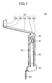
- the electromagnetic relay 1 of the embodiments of the present invention includes a fixed contact 11, a fixed contact spring 12, a fixed contact unit 10 having a fixed side arc runner 13, a movable contact 21, a movable contact spring 22, and a movable contact unit 20 having a movable side arc runner 23.
- an electric magnet unit 30 is provided on a side where the movable contact unit 20 is provided.
- An arming unit 40 is provided on an end of the electric magnet unit 30.
- the arming unit 40 is bent to be like a letter of "V”.
- the arming unit 40 is connected to the electromagnetic relay 1 so as to be movable around an axis at the center of the arming unit 40.
- the arming unit 40 has a first arm 40a in contact with the electric magnet unit 30 and a second arm 40b causing to operate a card 41 described later.
- the electric magnet unit 30 is formed by twin coils.
- the diameter of the single coil is ordinarily 2.5 times of that of the twin coil. Therefore, the electromagnetic relay 1 can be further miniaturized by using the twin coil.
- the electromagnetic relay 1 of the embodiment includes a permanent magnet 50 for removing arcs and a yoke 60 made of a magnetic material.
- An insulating portion 61 is provided on surfaces of the yokes 60 which face each other while sandwiching the fixed contact 11 and the movable contact 21.
- the yoke 60 is provided on both sides of the area having the fixed contact 11 and the movable contact 12 to apply a magnetic field to remove the arcs.
- the arcs can be transferred to the fixed side arc runner 13 and the movable side arc runner 23.
- the arcs are quickly removed from the fixed contact 11 and the movable contact 21.
- the fixed side arc runner 13 is formed in a longitudinal direction of the fixed contact spring 12 of the fixed contact unit 10 from a first end on a side of a base 80 to a second end opposite to the first end of the fixed side arc runner 13 beyond the fixed contact.
- the movable side arc runner 23 is formed in a longitudinal direction of the movable contact spring 22 of the movable contact unit 20. Beyond the movable contact, the movable side arc runner 23 is gradually apart from the movable contact and also apart from the fixed side arc runner 13 along a direction from a first end on a side of the base 80 toward a second end opposite to the first end of the movable side arc runner 23.
- the distance between the fixed side arc runner 13 and the movable side arc runner 23 is also increased to thereby enable the arcs smoothly running while increasing intervals of the arcs.
- An arc extinguishing grid 70 is provided between the second end of the fixed side arc runner 13 and the second end of movable side arc runner 23.
- the arcs run to the second end of the fixed side arc runner 13 and the second end of the movable side arc runner 23, and may be extinguished by the arc extinguishing grid 70. Therefore, in order to efficiently and smoothly extinguish the arcs with the arc extinguishing grid 70, the arc extinguishing grid 70 is preferably provided between the second end of the fixed side arc runner 13 and the second end of the movable side arc runner 23.
- the fixed contact unit 10, the movable contact unit 20, and the electric magnet unit 30 are mounted on a first surface of the base 80.
- Terminals 81, 82 and 83 are mounted on the other surface of the base 80.
- the terminals 81, 82 and 83 are connected to the fixed contact unit 10, the movable contact unit 20, and the electric magnet unit 30, respectively.
- the case 90 and the cover 92 being parts of a casing are formed to cover a fixed contact unit 10, the movable contact unit 20, the electric magnet unit 30, the arming unit 40, the permanent magnet 50, the yoke 60, the arc extinguishing grid 70 and so on which are arranged on the first surface of the base 80 and are connected to the base 80.
- an exhaust port 95 is formed by the case 90 and the cover 92 in the electromagnetic relay 1 of the embodiment, the exhaust port 95 is described in detail later.
- FIG. 3 illustrates a portion of the electromagnetic relay 1 viewed from the same direction as that in FIG. 1 .
- FIG. 4 illustrates a portion of the electromagnetic relay 1 viewed in a direction of the arrow D1 in FIG. 1
- FIG. 5 illustrates a portion of the electromagnetic relay 1 viewed in a direction of the arrow D2 in FIG. 1 .
- the permanent magnet 50 is described.
- the permanent magnet may be a samarium-cobalt magnet, a neodymium magnet, a ferrite magnet or the like.
- the samarium-cobalt magnet is preferable in view of a magnetic force and durability.
- the two yokes 60 are provided so as to sandwich the fixed contact 11 and the movable contact 21 on both sides of the two yokes 50.
- the yoke 60 is made of a material containing iron, cobalt, or nickel, for example, and shaped like a plate.
- the yokes are arranged to apply the magnetic field, which is generated by the permanent magnet 50, in a direction substantially perpendicular to the longitudinal direction of the fixed contact spring 12 and the longitudinal direction of the movable contact spring 22.
- the yokes 60 are shaped like a flat plate and installed so as to be substantially parallel with each other.
- One of the yokes 60 contacts the south (S) pole and the other one of the yokes 60 contacts the north (N) pole by a magnetic force.
- a magnetic flux generated by the permanent magnet 50 exists in between the pair of yokes 60 thereby generating a magnetic field in a space between the yokes 60.
- the direction of the magnetic flux is substantially perpendicular to the longitudinal directions of the fixed contact spring and the movable contact spring and is substantially perpendicular to a direction of separating the movable contact 21 from the fixed contact 11.
- the magnetic field generated by the permanent magnet 50 exists strongly in a predetermined direction in the space sandwiched by the yokes 60 of the embodiment.
- the fixed contact 11, the movable contact 21, the fixed side arc runner 13, the movable side arc runner 23 and the arc extinguishing grid 70 exist in the space.
- the direction of the magnetic flux generated by the permanent magnet and sandwiched by the yokes 60, the direction of separating the movable contact 21 from the fixed contact 11, and the longitudinal direction of the fixed side arc runner 13 are mutually orthogonal (perpendicular).
- an electric current flows from the fixed contact 11 to the movable contact 21.
- the electric current flows from the terminal 81 connected to the fixed contact unit 10, through the fixed contact 11 and the movable contact 21 to the terminal 82 connected to the movable contact unit 20.
- the circuit of the electromagnetic relay 1 is configured such that the electric current flows from the fixed contact 11 to the movable contact 21.
- the fixed contact spring 12 is thick enough to obtain a great thermal capacity.
- a thermal influence received by the fixed contact spring 12 or the like upon hitting of the electrons is small.
- the movable contact spring 22 is thin, the thermal capacity of the movable contact spring 22 is small. Therefore, when the electrons hit the movable contact 11, the probability of melting and deforming the movable contact spring 22 by the thermal influence caused by hitting of the electrons is high. Therefore, the circuit of the electromagnetic relay 1 is configured such that the electric current flows from the fixed contact 11 to the movable contact 21, said differently, the electrons move from the movable contact 21 to the fixed contact 11.
- the magnetic material forming the yokes 60 is a metallic material containing a magnetic material containing Fe, Ni and Co. Therefore, the yokes 60 have electrical conductivity, and the generated arcs may be prone to move toward the yokes 60 due to attraction by the electrical conductivity of the yokes 60.
- the metallic material may be shielded by the insulating material to thereby prevent the arcs from moving toward the yokes.
- an insulating portion 61 is provided on surfaces of the yokes 60 on which the yokes 60 face each other. Therefore, it is possible to prevent the arcs generated between the facing surfaces of the yokes 60 from being attracted by and moving toward the yokes 60.
- the insulating portion 61 is made of an insulating material, specifically an inorganic insulating material such as aluminum oxide, silicon oxide, aluminum nitride and ceramics or an organic insulating material such as a resin material.
- the insulating portion 61 may be shaped like a flat plate so as to cover the yoke 60 or formed by coating an insulating material on the surface of the yoke 60.
- the resin material is a fluorine resin, a poly-p-xylylene resin or the like.
- the melting point of the material of the insulating portion 61 is high enough to prevent such melting.
- the insulating portions are formed to substantially cover the mutually facing surfaces of the yokes 60. In a space between the insulating portions formed on the yokes 60, the fixed contact 11, the movable contact 21, the fixed side arc runner 13, the movable side arc runner 23 and the arc extinguishing grid 70 are sandwiched.
- the electromagnetic relay 1 includes the electric magnet unit 30 and the permanent magnet 50. Both of the electric magnet unit 30 and the permanent magnet 50 generate magnetic fields. However, the electric magnet unit 30 has a function of making the movable contact 21 contact or separate from the fixed contact 11, and the permanent magnet has a function of removing arcs generated between the fixed contact 11 and the movable contact 21. Thus, the electric magnet unit 30 and the permanent magnet 50 have different functions.
- the electric magnet unit 30 is arranged at an upper left portion of the electromagnetic relay 1 so as to sandwich the fixed contact and the movable contact 21, and the permanent magnet 50 is arranged at an upper right portion of the electromagnetic relay 1.
- the fixed contact 11 and the movable contact 21 are positioned between the electric magnet unit 30 and the permanent magnet 50.
- the electric magnet unit 30 for moving the movable contact 21 is positioned on the side of the movable contact 21 closer to the movable contact 21 than the side of the fixed contact 11.
- the permanent magnet 50 is arranged on the side of the fixed contact 11.
- the yokes 60 it is preferable to arrange the permanent magnet 50 in the vicinity of the fixed contact 11 and the movable contact 21.
- the fixed contact unit 10 is formed by punching a sheet of metallic plate and processing by bending the sheet of metallic plate.
- the fixed contact 11 is provided in the vicinity of the second end of the fixed contact spring 12.
- the first end of the fixed contact spring 12 is connected to the fixed side supporting portion 14.
- a fixed side frame portion 15 connected to the fixed side supporting portion 14 so as to surround the fixed contact spring 12. Therefore, the fixed contact spring 12 and the fixed side frame portion 15 are formed so as to be substantially parallel.
- the fixed contact spring 12 is formed by punching out the metallic plate, and the fixed side frame portion 15 is formed around the fixed contact spring 12.
- the fixed contact spring 12 and the fixed side frame portion 15 are connected via the fixed side supporting portion 14 at a portion corresponding to the remaining one side of the fixed contact spring 12 which is not punched out.
- the fixed contact spring 12 is displaced when the movable contact 21 contacts and pushes the fixed contact 11. Therefore, the fixed contact spring 12 can be biased as a spring.
- the fixed side frame portion 15 maintains its outer shape so as to be a predetermined shape without being deformed when the movable contact 11 contacts the fixed contact 21.
- a fixed side tab 16 to be described later is maintained to be at a predetermined position.
- the fixed side arc runner 13 is provided on the second end of the fixed side frame portion, which is opposite to the first end of the fixed side supporting portion 14, in the longitudinal direction of the fixed contact spring.
- the fixed side tab 16 is provided in the fixed side frame portion 15 toward the side of the fixed contact 11, i.e., in a direction opposite to the longitudinal direction toward the second end of the fixed side frame portion 15 (the fixed side arc runner 13).
- the fixed contact spring 12 is bent in the vicinity of a connecting portion between the fixed side supporting portion 14 and the fixed side frame portion 15 so as to be adjacent to the fixed side tab 16.
- the movable contact unit 20 is formed by punching out a sheet of metallic plate and processing by bending the sheet of metallic plate.
- the movable contact 21 is provided in the vicinity of a second end of the movable contact spring 22.
- the movable contact spring 22 is connected to a movable side supporting portion 24 at a first end opposite to the second end.
- a movable side frame portion 25 connected to the movable side supporting portion 24 so as to surround the periphery of the movable contact spring 22.
- the movable contact spring 22 is substantially parallel to the movable side frame portion 25.
- the movable contact spring 22 is formed by punching out the metallic plate, and the movable side frame portion 25 is formed around the movable contact spring 22.
- the movable contact spring 22 and the movable side frame portion 25 are connected via the movable side supporting portion 24 at a portion corresponding to the remaining one side of the movable contact spring 22 which is not punched out.
- the movable contact spring 22 is displaced when the movable contact 21 contacts and pushes the fixed contact 11. Therefore, the movable contact spring 22 can be biased as a spring.
- the movable side frame portion 25 maintains its outer shape so as to be a predetermined shape without being deformed when the movable contact 21 contacts the fixed contact 11.
- a movable side tab 26 to be described later is maintained to be at a predetermined position.
- the movable side arc runner 23 is provided on the second end of the movable side frame portion 25 opposite to the movable side supporting portion 24.
- the movable side arc runner 23 includes a connecting portion 23a formed along the longitudinal direction of the movable side frame portion 25, a linear portion 23c bent at the bending portion 23b, and an outer side portion 23e formed by bending the linear portion 23c at the bending portion 23d.
- the angle between the longitudinal direction of the linear portion 23c toward the outer side portion 23e and the movable side frame portion 25 is smaller than the right angle.
- the direction along the outer side portion 23e is substantially parallel to the longitudinal direction of the movable side frame portion 25 at the bent portion 23d.
- the bent portions 23b and 23d are shaped to have a predetermined roundness.
- the generated arcs can be smoothly moved at the bent portions 23b and 23d.
- the movable side frame portion 25 has a movable side tab 26 extending toward the movable contact 21 on a side opposite to the movable side arc runner 23.
- the angle between the linear portion 23c and the movable side frame portion 25 in the movable side arc runner 23 is smaller than the right angle.
- the linear portion 23c is gradually apart from the fixed side arc runner 13 toward the outer side portion 23e of the movable side arc runner 23. With this feature, the arcs can be smoothly moved through the linear portion 23c.
- the angle between the linear portion 23c and the movable side frame portion 25 is counted based on a line along the longitudinal direction of the movable side frame portion 25. When the linear portion 23c is not bent from the movable side frame portion 25, the angle is 0°. Further, the movable contact spring 22 is bent in the vicinity of a connecting portion between the movable side supporting portion and the movable contact spring 22 so that the movable side tab approaches the movable contact 21.
- the fixed side supporting portion 14 of the fixed contact unit 10 is fixed to the base 80.
- the movable side supporting portion 24 of the movable contact unit 20 is fixed to the base 80.
- the fixed contact unit 10 and the movable contact unit 20 are formed by processing each sheet of metallic plate. Therefore, the electromagnetic relay 1 can be formed at a low cost. Further, there is not a connecting member causing contact resistances between the fixed contact 11 and the fixed side arc runner 13 and between the movable contact 21 and the movable side arc runner 23. Therefore, the resistances are low to thereby further uniform the electric potential between the fixed contact 11 and the fixed side arc runner 13 and the electric potential between the movable contact 21 and the movable side arc runner 23. With this, the arcs generated between the fixed contact 11 and the movable contact 21 are smoothly transferred to the fixed side arc runner 13 and the movable side arc runner 23.
- FIG. 8 is an enlarged view of a contact portion between the fixed contact 11 and the movable contact 21 of the electromagnetic relay 1 of the embodiment.
- the fixed contact 11 is formed so as to approach the fixed side tab 16 connected to the fixed side arc runner 13.
- the movable contact 21 is formed to approach the movable side tab 26 connected to the movable side arc runner 23.
- the fixed contact 11 is adjacent to the fixed side tab 16 and the movable contact 21 is adjacent to the movable side tab 26 arcs are generated when the movable contact 21 is separated from the fixed contact 11.
- the generated arcs are apt to be transferred from a position between the fixed contact 11 and the movable contact 21 to a position between the fixed side tab 16 and the movable side tab 26.
- the arcs transferred between the fixed side tab 16 and the movable side tab 26 moves through the fixed side arc runner 13 and the movable side arc runner 23.
- the arcs generated in between the fixed contact 11 and the movable contact 21 can be transferred to the fixed side arc runner 13 and the movable side arc runner 23 to thereby reduce damage to the fixed contact 11 and the movable contact 21.
- the thermal capacity of the fixed contact 11 may be increased by providing a fixed contact assisting portion 111 for reinforcing the connecting portion between the fixed contact spring 12 and the fixed contact 11.
- a fixed side tab assisting portion 116 may be provided in the fixed side tab 16 to which the arcs transfer from the fixed contact 11 to thereby increase the thermal capacity of the fixed side tab 16.
- the thermal capacity of the movable contact 21 may be increased by providing a movable contact assisting portion 121 for reinforcing the connecting portion between the movable contact spring 22 and the movable contact 21.
- a movable side tab assisting portion 126 may be provided in the movable side tab 26 to which the arcs transfer from the movable contact 21 to thereby increase the thermal capacity of the movable side tab 26.
- the electromagnetic relay 1 of the embodiment can be formed by connecting members forming the electromagnetic relay 1 from one direction (parallel to the Z axis).
- the electric magnet unit 30 having the arming unit 40 connected to the base 80 of the electric magnet unit 30 is installed in step S102.
- the electric magnet unit 30 is installed so as to generate a magnetic field in the direction of Z axis.
- the arming unit 40 is installed so that the first arm 40a is positioned above the electric magnet unit 30.
- the fixed contact unit 10 and the movable contact unit 20 are installed in step S104. Specifically, the insulating case 91 having openings on both sides along the Z axis is connected to the base 80 in a direction parallel to the Z axis. Further, the fixed contact unit 10 and the movable contact unit 20 are connected to a portion of the base 80 in which the electric magnet unit 30 is not installed in a direction parallel to the Z axis so that the terminals 81 and 82 are positioned on the side of the base 80.
- the movable contact 20 is provided on the side in which the electric magnet unit 30 is installed and the movable contact 20 is connected to the base 80 so that the movable side arc runner 23 is positioned above the electric magnet unit 30 in an upper direction along the Z axis.
- step S106 the yoke 60, the insulating portion 61, the arc extinguishing grid 70 and the permanent magnet 50 are installed in step S106. Specifically, a lower opening of both the openings of the case 90 is connected to the base 80. At this time, the case 90 is connected to the base 80 in a direction parallel to the Z axis. Thereafter, the yoke 60, the insulating portion 61, the arc extinguishing grid 70, and the permanent magnet 50 are connected in a direction parallel to the Z axis.
- the cover 92 is installed in step S108. Specifically, the cover 92 is connected to the case 90 in the direction parallel to the Z axis so as to cover an upper opening of both the openings of the case 90.
- the electromagnetic relay 1 of the embodiment can be manufactured.
- the base 80, the case 90, the insulating case 91, the cover 92 or the like are formed by an insulating resin material.
- the base 80, the case 90 and the cover 92 forms a casing of the electromagnetic relay 1 of the present invention.
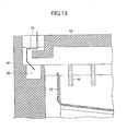
- FIG. 13 when arcs are generated, it is possible to prevent the pressure inside the casing from increasing by exhausting a gas generated by the arcs from an exhaust port 95 formed between the case 90 and the cover 92.
- the exhaust port 95 has plural bent portions to prevent dust or the like from intruding from the outside. By forming the bent portions, it is possible to prevent the dust or the like from intruding into the casing to a maximum extent.
- a dust catching portion 96 is provided in a portion of the exhaust port 95 to receive extraneous matters such as the dust intruding into the exhaust port 95 from the outside.
- an electromagnetic relay 1 having a structure with which arcs are hardly attracted by the yokes for applying a magnetic field to the neighboring portions of the contacts in order to ensure high reliability and safety.
- the electromagnetic relay for a voltage higher than that of the commercial power supply, the direct power source and so on with high reliability and safety.
- the present invention provides the electromagnetic relay having high reliability and safety and the manufacturing method of the electromagnetic relay. Especially, it is possible to provide the manufacturing method of the electromagnetic relay for a voltage higher than that of the commercial power supply, the direct power source and so on with high reliability and safety.
Landscapes
- Physics & Mathematics (AREA)
- Electromagnetism (AREA)
- Arc-Extinguishing Devices That Are Switches (AREA)
Claims (12)
- Ein elektromagnetisches Relais, umfassend:eine Festkontakteinheit (10), umfassend:einen Festkontakt (11); undeinen Festseiten-Bogenläufer (13), verbunden mit dem Festkontakt;eine bewegliche Kontakteinheit (20), umfassend:einen Rahmen der beweglichen Seite (25), welcher sich in einer longitudinalen Richtung des Festseiten-Bogenläufers erstreckt;eine bewegliche Kontaktfeder (22), bei welcher ein Ende mit einem Ende des Rahmens der beweglichen Seite verbunden ist;einen beweglicher Kontakt (21), vorgesehen an der beweglichen Kontaktfeder; undeinen Bogenläufer der beweglichen Seite (23), verbunden mit einem anderen Ende des Rahmens der beweglichen Seite, wobei der Bogenläufer der beweglichen Seite gebogen ist und sich von dem Rahmen der beweglichen Seite unter einem Winkel, geringer als ein rechter Winkel, erstreckt;einen Elektromagneten (30), ausgebildet zum Veranlassen, dass der bewegliche Kontakt den Festkontakt kontaktiert, durch Anwenden einer Kraft auf die bewegliche Kontaktfeder über eine Scharfstelleinheit (40);einen Magneten (50), ausgebildet zum Erzeugen eines magnetischen Feldes zwischen dem Festkontakt und dem beweglichen Kontakt;ein Paar von Jochen (60), welche jeweils aus einem magnetischen Material gefertigt sind, parallel angeordnet zum Einschieben des Festkontakts und des beweglichen Kontakts zwischen den Jochen und zum Anlegen des durch den Magneten erzeugten magnetischen Feldes an einen Bereich, an welchem jeweils der Festkontakt und der bewegliche Kontakt vorhanden sind;ein Paar isolierende Teile (61), vorgesehen auf einer inneren Oberfläche des Paares von Jochen, entsprechend dem Festkontakt und dem beweglichen Kontakt zugewandt; undein Bogenlöschgitter (70) zum Auslöschen von Bögen, vorgesehen zwischen dem Paar von Jochen.
- Das elektromagnetische Relais gemäß Anspruch 1,
wobei die isolierenden Teile (61) wie eine Platte geformt oder auf die Joche (60) geschichtet sind. - Das elektromagnetische Relais gemäß Anspruch 1,
wobei der Festseiten-Bogenläufer (13), der Bogenläufer der beweglichen Seite (23) und das Bogenlöschgitter (70) in einem zwischen dem Paar von isolierenden Teilen (61) eingeschobenen Raum vorhanden sind. - Das elektromagnetische Relais gemäß Anspruch 1,
wobei der Festkontakt (11) und der bewegliche Kontakt (21) zwischen dem Elektromagneten (30) und dem Magneten (50) positioniert sind. - Das elektromagnetische Relais gemäß Anspruch 1,
wobei, wenn der bewegliche Kontakt (21) den Festkontakt (11) kontaktiert, ein elektrischer Strom in eine Richtung von dem Festkontakt zu dem beweglichen Kontakt fliest. - Das elektromagnetische Relais gemäß Anspruch 5,
wobei eine Richtung eines Trennens eines Kontaktierens zwischen dem Festkontakt (11) und dem beweglichen Kontakt (21), eine Richtung des auf die Joche (60) angewendeten Magnetfeldes und die longitudinale Richtung des Festseiten-Bogenläufers (13) wechselseitig senkrecht zueinander sind. - Das elektromagnetische Relais gemäß Anspruch 1, weiter umfassend:eine Festseiten-Lasche (16), hervorstehend von dem Festseiten-Bogenläufer (13) zu dem Festkontakt (11), undeine Lasche der beweglichen Seite (26), hervorstehend von dem Bogenläufer der beweglichen Seite (23) zu dem beweglichen Kontakt (21).
- Das elektromagnetische Relais gemäß Anspruch 7,
wobei eine oder mehrere, ausgewählt aus einem Festseiten-Verbindungsteil, dem Verbindungsteil der beweglichen Seite, der Festseiten-Lasche (16) und der Lasche der beweglichen Seite (26) dicker als ein Rest ist, welcher nicht ausgewählt ist. - Das elektromagnetische Relais gemäß Anspruch 1,
wobei der Festkontakt (11) und der Festseiten-Bogenläufer (13) durch Verarbeiten einer einzelnen Metallplatte ausgebildet sind, und
der Rahmen der beweglichen Seite (25), die bewegliche Kontaktfeder (22) und der Bogenläufer der beweglichen Seite (23) durch Verarbeiten einer anderen einzelnen Metallplatte ausgebildet sind. - Das elektromagnetische Relais gemäß Anspruch 1, wobei die Festkontakteinheit (10) weiter umfasst:einen Festseiten-Rahmen (15), welcher sich in die longitudinale Richtung erstreckt; undeine Festkontaktfeder (12), bei welcher ein Ende mit einem Ende des Festseiten-Rahmens verbunden ist;wobei der Festkontakt (11) an dem anderen Ende der Festkontaktfeder vorgesehen ist; undder Festseiten-Bogenläufer (13) an dem anderen Ende des Festkontakt-Rahmens vorgesehen ist und sich in einer longitudinalen Richtung des Festkontakt-Rahmens erstreckt.
- Ein Verfahren zum Herstellen eines elektromagnetischen Relais, umfassend:Installieren einer Elektromagneteinheit (30) in einer Basis (80);Installieren einer Festkontakteinheit (10), umfassend einen Festkontakt (11) und einen Festseiten-Bogenläufer (13), verbunden mit dem Festkontakt, und eine bewegliche Kontakteinheit (20), umfassend einen Rahmen einer beweglichen Seite (25), welche sich in einer longitudinalen Richtung des Festseiten-Bogenläufers (13) erstreckt, eine bewegliche Kontaktfeder (22), bei welcher ein Ende mit einem Ende des Rahmens der beweglichen Seite verbunden ist, einen beweglichen Kontakt (21), vorgesehen an der beweglichen Kontaktfeder, und einen Bogenläufer der beweglichen Seite (23), verbunden mit einem anderen Ende des Rahmens der beweglichen Seite, sodass der Bogenläufer der beweglichen Seite gebogen ist und sich von dem Rahmen der beweglichen Seite unter einem Winkel, geringer als ein rechter Winkel, in einen Bereich erstreckt, bei welchem die Elektromagneteinheit nicht installiert ist;Installieren von Jochen (60), welche jeweils ein Bogenauslöschungsgitter (70) aufweisen, sodass die Joche parallel zum Einschieben des Festkontakts und des beweglichen Kontakts dazwischen angeordnet sind; undInstallieren eines Magneten (50) zum Erzeugen eines magnetischen Flusses zwischen dem Festkontakt und dem beweglichen Kontakt,wobei die Festkontakteinheit, bewegliche Kontakteinheit, die Joche, das Bogenauslöschungsgitter und der Magnet von einer einzigen Richtung aus installiert werden.
- Das Verfahren zum Herstellen des elektromagnetischen Relais gemäß Anspruch 11,
wobei die bewegliche Kontaktfeder (22) so installiert ist, dass eine longitudinale Richtung der beweglichen Kontaktfeder identisch zu der einzigen Richtung ist.
Applications Claiming Priority (3)
| Application Number | Priority Date | Filing Date | Title |
|---|---|---|---|
| JP2011127740A JP5727871B2 (ja) | 2011-06-07 | 2011-06-07 | 電磁継電器 |
| JP2011127742A JP5890112B2 (ja) | 2011-06-07 | 2011-06-07 | 電磁継電器 |
| JP2011127741A JP5797464B2 (ja) | 2011-06-07 | 2011-06-07 | 電磁継電器 |
Publications (2)
| Publication Number | Publication Date |
|---|---|
| EP2533262A1 EP2533262A1 (de) | 2012-12-12 |
| EP2533262B1 true EP2533262B1 (de) | 2015-09-16 |
Family
ID=45992127
Family Applications (1)
| Application Number | Title | Priority Date | Filing Date |
|---|---|---|---|
| EP12165724.1A Not-in-force EP2533262B1 (de) | 2011-06-07 | 2012-04-26 | Elektromagnetisches Relais und Herstellungsverfahren dafür |
Country Status (5)
| Country | Link |
|---|---|
| US (1) | US8446235B2 (de) |
| EP (1) | EP2533262B1 (de) |
| KR (1) | KR101354405B1 (de) |
| CN (1) | CN102820172B (de) |
| TW (1) | TWI479529B (de) |
Cited By (2)
| Publication number | Priority date | Publication date | Assignee | Title |
|---|---|---|---|---|
| KR101829574B1 (ko) | 2014-08-18 | 2018-02-14 | 미쓰비시덴키 가부시키가이샤 | 개폐 장치 |
| CN114270462A (zh) * | 2019-07-03 | 2022-04-01 | 埃伦贝格尔及珀恩斯根有限公司 | 电开关系统 |
Families Citing this family (33)
| Publication number | Priority date | Publication date | Assignee | Title |
|---|---|---|---|---|
| ITMI20111412A1 (it) * | 2011-07-28 | 2013-01-29 | Electrica Srl | Dispositivo a rele' a configurazione bilanciata con prestazioni migliorate |
| EP2650894B1 (de) * | 2012-04-12 | 2018-06-06 | ABB Oy | Elektrische Stromschaltungsvorrichtung |
| CN103456567B (zh) * | 2012-06-04 | 2017-09-19 | 松下知识产权经营株式会社 | 电磁继电器 |
| JP5992603B2 (ja) * | 2013-03-27 | 2016-09-14 | 三菱電機株式会社 | 開閉装置 |
| JP5756825B2 (ja) * | 2013-04-22 | 2015-07-29 | オムロン株式会社 | 電磁継電器 |
| CN105009248B (zh) * | 2013-07-05 | 2017-05-31 | 富士电机株式会社 | 电磁接触器 |
| JP2015035403A (ja) * | 2013-08-09 | 2015-02-19 | オムロン株式会社 | 接点機構およびこれを用いた電磁継電器 |
| JP6406596B2 (ja) * | 2014-05-12 | 2018-10-17 | パナソニックIpマネジメント株式会社 | 接点装置 |
| JP6091711B2 (ja) * | 2014-06-06 | 2017-03-08 | 三菱電機株式会社 | 開閉装置 |
| JP6433706B2 (ja) * | 2014-07-28 | 2018-12-05 | 富士通コンポーネント株式会社 | 電磁継電器及びコイル端子 |
| DE102014111901B4 (de) | 2014-08-20 | 2019-05-23 | Snaptrack, Inc. | Duplexer |
| DE102014111912B4 (de) | 2014-08-20 | 2024-06-13 | Snaptrack, Inc. | HF-Filter |
| CN107077996B (zh) * | 2014-12-05 | 2019-03-29 | 欧姆龙株式会社 | 电磁继电器 |
| JP6414453B2 (ja) | 2014-12-05 | 2018-10-31 | オムロン株式会社 | 電磁継電器 |
| JP2016110843A (ja) | 2014-12-05 | 2016-06-20 | オムロン株式会社 | 電磁継電器 |
| JP6447919B2 (ja) * | 2015-04-07 | 2019-01-09 | パナソニックIpマネジメント株式会社 | 電磁継電器 |
| TWI587346B (zh) * | 2015-07-22 | 2017-06-11 | 松川精密股份有限公司 | 具陶瓷複合材料之繼電器開關元件 |
| JP6631068B2 (ja) | 2015-07-27 | 2020-01-15 | オムロン株式会社 | 接点機構およびこれを用いた電磁継電器 |
| JP6808434B2 (ja) * | 2016-10-05 | 2021-01-06 | 富士通コンポーネント株式会社 | 電磁継電器 |
| JP6836241B2 (ja) * | 2016-12-27 | 2021-02-24 | 富士通コンポーネント株式会社 | 電磁継電器 |
| JP6909993B2 (ja) * | 2017-03-30 | 2021-07-28 | パナソニックIpマネジメント株式会社 | 電磁継電器 |
| CN107766655B (zh) * | 2017-10-23 | 2021-03-23 | 哈尔滨工业大学 | 一种电磁继电器永磁贮存退化表征参数的确定方法 |
| JP7014617B2 (ja) * | 2018-01-17 | 2022-02-01 | 富士通コンポーネント株式会社 | 電磁継電器 |
| US10930460B2 (en) * | 2019-02-14 | 2021-02-23 | Song Chuan Precision Co., Ltd. | Relay structure with heat dissipation function |
| JP7313168B2 (ja) * | 2019-03-19 | 2023-07-24 | 富士通コンポーネント株式会社 | 電磁継電器 |
| CN113963993A (zh) * | 2020-07-21 | 2022-01-21 | 海信(山东)冰箱有限公司 | 一种静音电磁继电器及冰箱 |
| JP7487647B2 (ja) | 2020-11-20 | 2024-05-21 | オムロン株式会社 | 電磁継電器 |
| JP2023000415A (ja) * | 2021-06-17 | 2023-01-04 | オムロン株式会社 | 電磁継電器 |
| JP2023004605A (ja) * | 2021-06-28 | 2023-01-17 | オムロン株式会社 | 電磁継電器 |
| JP2023008418A (ja) * | 2021-07-06 | 2023-01-19 | オムロン株式会社 | 電磁継電器 |
| US11688574B2 (en) * | 2021-09-13 | 2023-06-27 | Song Chuan Precision Co., Ltd. | Electromagnetic relay |
| CN216624127U (zh) * | 2021-12-31 | 2022-05-27 | 施耐德电器工业公司 | 动触头支架组件和接触器 |
| KR20230106298A (ko) | 2022-01-06 | 2023-07-13 | 엘에스일렉트릭(주) | 구동부 및 이를 포함하는 직류 릴레이 |
Family Cites Families (18)
| Publication number | Priority date | Publication date | Assignee | Title |
|---|---|---|---|---|
| US2875303A (en) * | 1954-10-22 | 1959-02-24 | Westinghouse Electric Corp | Circuit interrupter |
| US2875304A (en) * | 1956-03-30 | 1959-02-24 | Westinghouse Electric Corp | Circuit interrupter |
| JPS5713628A (en) * | 1980-06-27 | 1982-01-23 | Mitsubishi Electric Corp | Direct current electromagnetic contactor |
| US4451718A (en) * | 1981-02-27 | 1984-05-29 | Mitsubishi Denki Kabushiki Kaisha | Circuit breaker |
| US4546336A (en) * | 1983-09-02 | 1985-10-08 | Eaton Corporation | Residential circuit breaker with combination slot motor and arc chute |
| JP2658170B2 (ja) | 1988-05-11 | 1997-09-30 | オムロン株式会社 | 開閉器 |
| JP3465940B2 (ja) * | 1993-12-20 | 2003-11-10 | 日本信号株式会社 | プレーナー型電磁リレー及びその製造方法 |
| JP3321963B2 (ja) * | 1994-02-22 | 2002-09-09 | 株式会社デンソー | プランジャ型電磁継電器 |
| JP4038950B2 (ja) | 1999-12-16 | 2008-01-30 | 株式会社デンソー | 電磁継電器 |
| JP3758510B2 (ja) | 2001-02-23 | 2006-03-22 | 三菱電機株式会社 | 開閉器 |
| DE10356271B4 (de) * | 2003-11-28 | 2008-02-14 | Siemens Ag | Schaltgerät |
| JP4810937B2 (ja) | 2005-09-06 | 2011-11-09 | オムロン株式会社 | 開閉装置 |
| TW200802472A (en) * | 2006-06-30 | 2008-01-01 | Good Sky Electric Co Ltd | Electromagnetic relay |
| DE102006035844B4 (de) * | 2006-08-01 | 2008-06-19 | Schaltbau Gmbh | Schütz für Gleichstrom- und Wechselstrombetrieb |
| FR2916571B1 (fr) * | 2007-05-22 | 2009-09-11 | Schneider Electric Ind Sas | Chambre de coupure et disjoncteur equipe d'une telle chambre de coupure |
| US8193881B2 (en) * | 2007-09-14 | 2012-06-05 | Fujitsu Component Limited | Relay |
| JP5202072B2 (ja) | 2007-09-14 | 2013-06-05 | 富士通コンポーネント株式会社 | リレー |
| JP5573250B2 (ja) * | 2010-03-09 | 2014-08-20 | オムロン株式会社 | 封止接点装置 |
-
2012
- 2012-03-09 KR KR1020120024652A patent/KR101354405B1/ko active IP Right Grant
- 2012-04-19 US US13/450,706 patent/US8446235B2/en not_active Expired - Fee Related
- 2012-04-26 EP EP12165724.1A patent/EP2533262B1/de not_active Not-in-force
- 2012-05-14 TW TW101117131A patent/TWI479529B/zh not_active IP Right Cessation
- 2012-05-18 CN CN201210156597.XA patent/CN102820172B/zh not_active Expired - Fee Related
Cited By (2)
| Publication number | Priority date | Publication date | Assignee | Title |
|---|---|---|---|---|
| KR101829574B1 (ko) | 2014-08-18 | 2018-02-14 | 미쓰비시덴키 가부시키가이샤 | 개폐 장치 |
| CN114270462A (zh) * | 2019-07-03 | 2022-04-01 | 埃伦贝格尔及珀恩斯根有限公司 | 电开关系统 |
Also Published As
| Publication number | Publication date |
|---|---|
| US8446235B2 (en) | 2013-05-21 |
| EP2533262A1 (de) | 2012-12-12 |
| CN102820172A (zh) | 2012-12-12 |
| US20120313737A1 (en) | 2012-12-13 |
| TW201310489A (zh) | 2013-03-01 |
| KR101354405B1 (ko) | 2014-01-22 |
| CN102820172B (zh) | 2015-04-01 |
| KR20120135861A (ko) | 2012-12-17 |
| TWI479529B (zh) | 2015-04-01 |
Similar Documents
| Publication | Publication Date | Title |
|---|---|---|
| EP2533262B1 (de) | Elektromagnetisches Relais und Herstellungsverfahren dafür | |
| EP3940734B1 (de) | Elektromagnetisches relais | |
| EP2472538B1 (de) | Elektromagnetisches relais | |
| US8847714B2 (en) | Relay | |
| US8330564B2 (en) | Switching devices configured to control magnetic fields to maintain an electrical connection | |
| US9013253B2 (en) | Relay | |
| EP3264437B1 (de) | Elektromagnetisches relais | |
| EP2822011B1 (de) | Elektromagnetisches Relais | |
| EP2654063B1 (de) | Elektromagnetisches Relais | |
| US9704683B2 (en) | Double-break relay | |
| EP2919252B1 (de) | Elektromagnetisches Relais | |
| CN108140512A (zh) | 电磁继电器 | |
| JP5549642B2 (ja) | 継電器 | |
| JP5727871B2 (ja) | 電磁継電器 | |
| US5014027A (en) | Electromagnetic contactor | |
| JP2012256453A (ja) | 電磁継電器 | |
| JP5797464B2 (ja) | 電磁継電器 | |
| WO2021215525A1 (ja) | アーク拘束機構 |
Legal Events
| Date | Code | Title | Description |
|---|---|---|---|
| PUAI | Public reference made under article 153(3) epc to a published international application that has entered the european phase |
Free format text: ORIGINAL CODE: 0009012 |
|
| AK | Designated contracting states |
Kind code of ref document: A1 Designated state(s): AL AT BE BG CH CY CZ DE DK EE ES FI FR GB GR HR HU IE IS IT LI LT LU LV MC MK MT NL NO PL PT RO RS SE SI SK SM TR |
|
| AX | Request for extension of the european patent |
Extension state: BA ME |
|
| 17P | Request for examination filed |
Effective date: 20130605 |
|
| RBV | Designated contracting states (corrected) |
Designated state(s): AL AT BE BG CH CY CZ DE DK EE ES FI FR GB GR HR HU IE IS IT LI LT LU LV MC MK MT NL NO PL PT RO RS SE SI SK SM TR |
|
| GRAP | Despatch of communication of intention to grant a patent |
Free format text: ORIGINAL CODE: EPIDOSNIGR1 |
|
| RIC1 | Information provided on ipc code assigned before grant |
Ipc: H01H 50/56 20060101ALI20150324BHEP Ipc: H01H 51/06 20060101AFI20150324BHEP |
|
| INTG | Intention to grant announced |
Effective date: 20150410 |
|
| GRAS | Grant fee paid |
Free format text: ORIGINAL CODE: EPIDOSNIGR3 |
|
| GRAA | (expected) grant |
Free format text: ORIGINAL CODE: 0009210 |
|
| AK | Designated contracting states |
Kind code of ref document: B1 Designated state(s): AL AT BE BG CH CY CZ DE DK EE ES FI FR GB GR HR HU IE IS IT LI LT LU LV MC MK MT NL NO PL PT RO RS SE SI SK SM TR |
|
| REG | Reference to a national code |
Ref country code: GB Ref legal event code: FG4D |
|
| REG | Reference to a national code |
Ref country code: CH Ref legal event code: EP |
|
| REG | Reference to a national code |
Ref country code: IE Ref legal event code: FG4D |
|
| REG | Reference to a national code |
Ref country code: AT Ref legal event code: REF Ref document number: 750384 Country of ref document: AT Kind code of ref document: T Effective date: 20151015 |
|
| REG | Reference to a national code |
Ref country code: DE Ref legal event code: R096 Ref document number: 602012010565 Country of ref document: DE |
|
| REG | Reference to a national code |
Ref country code: NL Ref legal event code: MP Effective date: 20150916 |
|
| PG25 | Lapsed in a contracting state [announced via postgrant information from national office to epo] |
Ref country code: NO Free format text: LAPSE BECAUSE OF FAILURE TO SUBMIT A TRANSLATION OF THE DESCRIPTION OR TO PAY THE FEE WITHIN THE PRESCRIBED TIME-LIMIT Effective date: 20151216 Ref country code: LV Free format text: LAPSE BECAUSE OF FAILURE TO SUBMIT A TRANSLATION OF THE DESCRIPTION OR TO PAY THE FEE WITHIN THE PRESCRIBED TIME-LIMIT Effective date: 20150916 Ref country code: GR Free format text: LAPSE BECAUSE OF FAILURE TO SUBMIT A TRANSLATION OF THE DESCRIPTION OR TO PAY THE FEE WITHIN THE PRESCRIBED TIME-LIMIT Effective date: 20151217 Ref country code: FI Free format text: LAPSE BECAUSE OF FAILURE TO SUBMIT A TRANSLATION OF THE DESCRIPTION OR TO PAY THE FEE WITHIN THE PRESCRIBED TIME-LIMIT Effective date: 20150916 Ref country code: LT Free format text: LAPSE BECAUSE OF FAILURE TO SUBMIT A TRANSLATION OF THE DESCRIPTION OR TO PAY THE FEE WITHIN THE PRESCRIBED TIME-LIMIT Effective date: 20150916 |
|
| REG | Reference to a national code |
Ref country code: LT Ref legal event code: MG4D |
|
| REG | Reference to a national code |
Ref country code: AT Ref legal event code: MK05 Ref document number: 750384 Country of ref document: AT Kind code of ref document: T Effective date: 20150916 |
|
| PG25 | Lapsed in a contracting state [announced via postgrant information from national office to epo] |
Ref country code: RS Free format text: LAPSE BECAUSE OF FAILURE TO SUBMIT A TRANSLATION OF THE DESCRIPTION OR TO PAY THE FEE WITHIN THE PRESCRIBED TIME-LIMIT Effective date: 20150916 Ref country code: HR Free format text: LAPSE BECAUSE OF FAILURE TO SUBMIT A TRANSLATION OF THE DESCRIPTION OR TO PAY THE FEE WITHIN THE PRESCRIBED TIME-LIMIT Effective date: 20150916 Ref country code: SE Free format text: LAPSE BECAUSE OF FAILURE TO SUBMIT A TRANSLATION OF THE DESCRIPTION OR TO PAY THE FEE WITHIN THE PRESCRIBED TIME-LIMIT Effective date: 20150916 |
|
| PG25 | Lapsed in a contracting state [announced via postgrant information from national office to epo] |
Ref country code: NL Free format text: LAPSE BECAUSE OF FAILURE TO SUBMIT A TRANSLATION OF THE DESCRIPTION OR TO PAY THE FEE WITHIN THE PRESCRIBED TIME-LIMIT Effective date: 20150916 |
|
| REG | Reference to a national code |
Ref country code: FR Ref legal event code: PLFP Year of fee payment: 5 |
|
| PG25 | Lapsed in a contracting state [announced via postgrant information from national office to epo] |
Ref country code: SK Free format text: LAPSE BECAUSE OF FAILURE TO SUBMIT A TRANSLATION OF THE DESCRIPTION OR TO PAY THE FEE WITHIN THE PRESCRIBED TIME-LIMIT Effective date: 20150916 Ref country code: IT Free format text: LAPSE BECAUSE OF FAILURE TO SUBMIT A TRANSLATION OF THE DESCRIPTION OR TO PAY THE FEE WITHIN THE PRESCRIBED TIME-LIMIT Effective date: 20150916 Ref country code: IS Free format text: LAPSE BECAUSE OF FAILURE TO SUBMIT A TRANSLATION OF THE DESCRIPTION OR TO PAY THE FEE WITHIN THE PRESCRIBED TIME-LIMIT Effective date: 20160116 Ref country code: EE Free format text: LAPSE BECAUSE OF FAILURE TO SUBMIT A TRANSLATION OF THE DESCRIPTION OR TO PAY THE FEE WITHIN THE PRESCRIBED TIME-LIMIT Effective date: 20150916 Ref country code: ES Free format text: LAPSE BECAUSE OF FAILURE TO SUBMIT A TRANSLATION OF THE DESCRIPTION OR TO PAY THE FEE WITHIN THE PRESCRIBED TIME-LIMIT Effective date: 20150916 Ref country code: CZ Free format text: LAPSE BECAUSE OF FAILURE TO SUBMIT A TRANSLATION OF THE DESCRIPTION OR TO PAY THE FEE WITHIN THE PRESCRIBED TIME-LIMIT Effective date: 20150916 |
|
| PG25 | Lapsed in a contracting state [announced via postgrant information from national office to epo] |
Ref country code: RO Free format text: LAPSE BECAUSE OF FAILURE TO SUBMIT A TRANSLATION OF THE DESCRIPTION OR TO PAY THE FEE WITHIN THE PRESCRIBED TIME-LIMIT Effective date: 20150916 Ref country code: PL Free format text: LAPSE BECAUSE OF FAILURE TO SUBMIT A TRANSLATION OF THE DESCRIPTION OR TO PAY THE FEE WITHIN THE PRESCRIBED TIME-LIMIT Effective date: 20150916 Ref country code: PT Free format text: LAPSE BECAUSE OF FAILURE TO SUBMIT A TRANSLATION OF THE DESCRIPTION OR TO PAY THE FEE WITHIN THE PRESCRIBED TIME-LIMIT Effective date: 20160118 Ref country code: AT Free format text: LAPSE BECAUSE OF FAILURE TO SUBMIT A TRANSLATION OF THE DESCRIPTION OR TO PAY THE FEE WITHIN THE PRESCRIBED TIME-LIMIT Effective date: 20150916 |
|
| REG | Reference to a national code |
Ref country code: DE Ref legal event code: R097 Ref document number: 602012010565 Country of ref document: DE |
|
| PLBE | No opposition filed within time limit |
Free format text: ORIGINAL CODE: 0009261 |
|
| STAA | Information on the status of an ep patent application or granted ep patent |
Free format text: STATUS: NO OPPOSITION FILED WITHIN TIME LIMIT |
|
| 26N | No opposition filed |
Effective date: 20160617 |
|
| PG25 | Lapsed in a contracting state [announced via postgrant information from national office to epo] |
Ref country code: DK Free format text: LAPSE BECAUSE OF FAILURE TO SUBMIT A TRANSLATION OF THE DESCRIPTION OR TO PAY THE FEE WITHIN THE PRESCRIBED TIME-LIMIT Effective date: 20150916 Ref country code: BE Free format text: LAPSE BECAUSE OF NON-PAYMENT OF DUE FEES Effective date: 20160430 |
|
| PG25 | Lapsed in a contracting state [announced via postgrant information from national office to epo] |
Ref country code: SI Free format text: LAPSE BECAUSE OF FAILURE TO SUBMIT A TRANSLATION OF THE DESCRIPTION OR TO PAY THE FEE WITHIN THE PRESCRIBED TIME-LIMIT Effective date: 20150916 |
|
| REG | Reference to a national code |
Ref country code: CH Ref legal event code: PL |
|
| PG25 | Lapsed in a contracting state [announced via postgrant information from national office to epo] |
Ref country code: BE Free format text: LAPSE BECAUSE OF FAILURE TO SUBMIT A TRANSLATION OF THE DESCRIPTION OR TO PAY THE FEE WITHIN THE PRESCRIBED TIME-LIMIT Effective date: 20150916 Ref country code: LU Free format text: LAPSE BECAUSE OF FAILURE TO SUBMIT A TRANSLATION OF THE DESCRIPTION OR TO PAY THE FEE WITHIN THE PRESCRIBED TIME-LIMIT Effective date: 20160426 |
|
| REG | Reference to a national code |
Ref country code: IE Ref legal event code: MM4A |
|
| PG25 | Lapsed in a contracting state [announced via postgrant information from national office to epo] |
Ref country code: LI Free format text: LAPSE BECAUSE OF NON-PAYMENT OF DUE FEES Effective date: 20160430 Ref country code: CH Free format text: LAPSE BECAUSE OF NON-PAYMENT OF DUE FEES Effective date: 20160430 |
|
| REG | Reference to a national code |
Ref country code: FR Ref legal event code: PLFP Year of fee payment: 6 |
|
| PG25 | Lapsed in a contracting state [announced via postgrant information from national office to epo] |
Ref country code: IE Free format text: LAPSE BECAUSE OF NON-PAYMENT OF DUE FEES Effective date: 20160426 |
|
| REG | Reference to a national code |
Ref country code: FR Ref legal event code: PLFP Year of fee payment: 7 |
|
| PGFP | Annual fee paid to national office [announced via postgrant information from national office to epo] |
Ref country code: GB Payment date: 20180329 Year of fee payment: 7 |
|
| PG25 | Lapsed in a contracting state [announced via postgrant information from national office to epo] |
Ref country code: SM Free format text: LAPSE BECAUSE OF FAILURE TO SUBMIT A TRANSLATION OF THE DESCRIPTION OR TO PAY THE FEE WITHIN THE PRESCRIBED TIME-LIMIT Effective date: 20150916 Ref country code: HU Free format text: LAPSE BECAUSE OF FAILURE TO SUBMIT A TRANSLATION OF THE DESCRIPTION OR TO PAY THE FEE WITHIN THE PRESCRIBED TIME-LIMIT; INVALID AB INITIO Effective date: 20120426 Ref country code: CY Free format text: LAPSE BECAUSE OF FAILURE TO SUBMIT A TRANSLATION OF THE DESCRIPTION OR TO PAY THE FEE WITHIN THE PRESCRIBED TIME-LIMIT Effective date: 20150916 |
|
| PG25 | Lapsed in a contracting state [announced via postgrant information from national office to epo] |
Ref country code: MC Free format text: LAPSE BECAUSE OF FAILURE TO SUBMIT A TRANSLATION OF THE DESCRIPTION OR TO PAY THE FEE WITHIN THE PRESCRIBED TIME-LIMIT Effective date: 20150916 Ref country code: TR Free format text: LAPSE BECAUSE OF FAILURE TO SUBMIT A TRANSLATION OF THE DESCRIPTION OR TO PAY THE FEE WITHIN THE PRESCRIBED TIME-LIMIT Effective date: 20150916 Ref country code: MT Free format text: LAPSE BECAUSE OF NON-PAYMENT OF DUE FEES Effective date: 20160430 Ref country code: MK Free format text: LAPSE BECAUSE OF FAILURE TO SUBMIT A TRANSLATION OF THE DESCRIPTION OR TO PAY THE FEE WITHIN THE PRESCRIBED TIME-LIMIT Effective date: 20150916 |
|
| PG25 | Lapsed in a contracting state [announced via postgrant information from national office to epo] |
Ref country code: BG Free format text: LAPSE BECAUSE OF FAILURE TO SUBMIT A TRANSLATION OF THE DESCRIPTION OR TO PAY THE FEE WITHIN THE PRESCRIBED TIME-LIMIT Effective date: 20150916 |
|
| PGFP | Annual fee paid to national office [announced via postgrant information from national office to epo] |
Ref country code: DE Payment date: 20180410 Year of fee payment: 7 |
|
| PG25 | Lapsed in a contracting state [announced via postgrant information from national office to epo] |
Ref country code: AL Free format text: LAPSE BECAUSE OF FAILURE TO SUBMIT A TRANSLATION OF THE DESCRIPTION OR TO PAY THE FEE WITHIN THE PRESCRIBED TIME-LIMIT Effective date: 20150916 |
|
| PGFP | Annual fee paid to national office [announced via postgrant information from national office to epo] |
Ref country code: FR Payment date: 20190313 Year of fee payment: 8 |
|
| REG | Reference to a national code |
Ref country code: DE Ref legal event code: R119 Ref document number: 602012010565 Country of ref document: DE |
|
| GBPC | Gb: european patent ceased through non-payment of renewal fee |
Effective date: 20190426 |
|
| PG25 | Lapsed in a contracting state [announced via postgrant information from national office to epo] |
Ref country code: DE Free format text: LAPSE BECAUSE OF NON-PAYMENT OF DUE FEES Effective date: 20191101 Ref country code: GB Free format text: LAPSE BECAUSE OF NON-PAYMENT OF DUE FEES Effective date: 20190426 |
|
| PG25 | Lapsed in a contracting state [announced via postgrant information from national office to epo] |
Ref country code: FR Free format text: LAPSE BECAUSE OF NON-PAYMENT OF DUE FEES Effective date: 20200430 |