EP2533011A2 - Compensation dynamique d'amplitude moteur d'un gyroscope pour une meilleure estimation du taux lors de son démarrage. - Google Patents
Compensation dynamique d'amplitude moteur d'un gyroscope pour une meilleure estimation du taux lors de son démarrage. Download PDFInfo
- Publication number
- EP2533011A2 EP2533011A2 EP12169172A EP12169172A EP2533011A2 EP 2533011 A2 EP2533011 A2 EP 2533011A2 EP 12169172 A EP12169172 A EP 12169172A EP 12169172 A EP12169172 A EP 12169172A EP 2533011 A2 EP2533011 A2 EP 2533011A2
- Authority
- EP
- European Patent Office
- Prior art keywords
- gyroscope
- motor amplitude
- signal
- rate
- motor
- Prior art date
- Legal status (The legal status is an assumption and is not a legal conclusion. Google has not performed a legal analysis and makes no representation as to the accuracy of the status listed.)
- Granted
Links
Images


Classifications
-
- G—PHYSICS
- G01—MEASURING; TESTING
- G01C—MEASURING DISTANCES, LEVELS OR BEARINGS; SURVEYING; NAVIGATION; GYROSCOPIC INSTRUMENTS; PHOTOGRAMMETRY OR VIDEOGRAMMETRY
- G01C19/00—Gyroscopes; Turn-sensitive devices using vibrating masses; Turn-sensitive devices without moving masses; Measuring angular rate using gyroscopic effects
- G01C19/02—Rotary gyroscopes
- G01C19/04—Details
-
- G—PHYSICS
- G01—MEASURING; TESTING
- G01C—MEASURING DISTANCES, LEVELS OR BEARINGS; SURVEYING; NAVIGATION; GYROSCOPIC INSTRUMENTS; PHOTOGRAMMETRY OR VIDEOGRAMMETRY
- G01C19/00—Gyroscopes; Turn-sensitive devices using vibrating masses; Turn-sensitive devices without moving masses; Measuring angular rate using gyroscopic effects
- G01C19/56—Turn-sensitive devices using vibrating masses, e.g. vibratory angular rate sensors based on Coriolis forces
- G01C19/5776—Signal processing not specific to any of the devices covered by groups G01C19/5607 - G01C19/5719
-
- G—PHYSICS
- G01—MEASURING; TESTING
- G01C—MEASURING DISTANCES, LEVELS OR BEARINGS; SURVEYING; NAVIGATION; GYROSCOPIC INSTRUMENTS; PHOTOGRAMMETRY OR VIDEOGRAMMETRY
- G01C25/00—Manufacturing, calibrating, cleaning, or repairing instruments or devices referred to in the other groups of this subclass
- G01C25/005—Manufacturing, calibrating, cleaning, or repairing instruments or devices referred to in the other groups of this subclass initial alignment, calibration or starting-up of inertial devices
-
- Y—GENERAL TAGGING OF NEW TECHNOLOGICAL DEVELOPMENTS; GENERAL TAGGING OF CROSS-SECTIONAL TECHNOLOGIES SPANNING OVER SEVERAL SECTIONS OF THE IPC; TECHNICAL SUBJECTS COVERED BY FORMER USPC CROSS-REFERENCE ART COLLECTIONS [XRACs] AND DIGESTS
- Y10—TECHNICAL SUBJECTS COVERED BY FORMER USPC
- Y10T—TECHNICAL SUBJECTS COVERED BY FORMER US CLASSIFICATION
- Y10T74/00—Machine element or mechanism
- Y10T74/12—Gyroscopes
- Y10T74/1229—Gyroscope control
Definitions
- the gyroscope motor takes a finite time to reach full steady state amplitude. During this time, rate estimates (if needed) are generally not accurate. Rate sensing with gyroscopes, such as a tuning fork gyroscope, have been largely avoided with current methods until the gyroscope motor is up and running in a steady state fashion.
- the sensed rate is proportional to the peak-to-peak amplitude of the oscillating proof-mass. Since this amplitude starts at zero (prior to power being applied) and then grows to final steady state amplitude over a period of time during startup, sensing rate during this time has not been feasible. Rather, sensing rate has been limited to periods after steady state motor amplitude is achieved.
- Delays in achievable rate sensing from time of power application can be significant, depending upon how long it takes for the gyroscope motor to achieve full amplitude.
- Some gyroscope applications call for accurate performance very shortly after activation.
- current tuning fork gyroscope devices such as those used in inertial measurement units (IMUs) and rate sensors can take approximately 0.4 to 3 seconds to reach accurate rate sensing operation. This delay can be intolerable for highly accurate guidance applications that require rate sensing information at the earliest possible point after power application.
- a system and method for gyroscope dynamic motor amplitude compensation during startup for improved rate sensing comprises at least one gyroscope, at least one processor in operative communication with the gyroscope, and at least one memory unit operatively coupled to the processor.
- the memory unit and the processor are configured to respectively store and execute program modules including an a-priori motor amplitude module configured to generate an a-priori motor amplitude signal based on a model of gyroscope motor amplitude growth during startup; a steady state scale factor module configured to generate a steady state scale factor signal; and a dynamic motor amplitude compensation module configured to receive the a-priori motor amplitude signal from the motor amplitude module, and the steady state scale factor signal from the steady state scale factor module.
- a rate motion is sensed by the gyroscope and a sensed rate signal is output by the gyroscope.
- the dynamic motor amplitude compensation module receives a measured motor amplitude signal from the gyroscope, an a-priori motor amplitude signal from the motor amplitude module, or a combination thereof.
- the dynamic motor amplitude compensation module outputs a time varying scale factor that is applied to the sensed rate signal to produce an early and accurate sensed rate from the gyroscope during the startup phase.
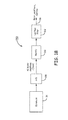
- Figure 1A is a block diagram of a control system for gyroscope dynamic motor amplitude compensation according to one embodiment
- Figure 1B is a block diagram of a supporting system for gyroscope dynamic motor amplitude compensation according to one embodiment
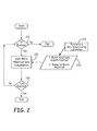
- Figure 2 is a flow diagram of a process for dynamic scale factor compensation employed in the control system of Figure 1A ;
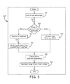
- Figure 3 is a flow diagram of a motor amplitude rate compensation algorithm employed in the process of Figure 2 ;
- Figure 4 is a graphical plot showing the results of a gyroscope start test with motor amplitude rate compensation
- Figure 5 is a graphical plot showing data from eight gyroscope turn-ons while at rate
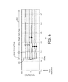
- Figure 6 is a graphical plot showing the same data as the plot of Figure 5 , but with motor amplitude rate compensation applied;
- Figure 7 is a timeline diagram showing the main phases of gyroscope startup.
- Figure 8 is a block diagram of one embodiment of a computer system that can implement a process for gyroscope dynamic motor amplitude compensation.
- a system and method are provided for gyroscope dynamic motor amplitude compensation, which enhances early rate estimation during gyroscope startup.
- the actual gyroscope scale factor is changing.
- the present approach allows rate sensing to be achieved during the startup phase of a gyroscope by applying a dynamically changing scale factor, which is a function of instantaneous motor amplitude. The result allows accurate rate sensing earlier in the power-up cycle of the gyroscope.
- a control system for a gyroscope dynamically uses motor amplitude at startup to adjust a scale factor, allowing early rate sensing before full and stable motor amplitude is achieved.
- the gyroscope motor amplitude between initial power application and steady state operation can be (1) measured in real-time, or can be (2) characterized a-priori based upon a mathematical model.
- rate sensing via dynamic scale factor compensation can be derived from a real-time motor amplitude measurement, during the period from initial motor start to final steady state motor operation.
- rate sensing via dynamic scale factor compensation can be provided using a-priori mathematical characterization of motor amplitude, during the period from initial motor start to final steady state motor operation.
- a dynamic scale factor function provides for stable rate sensing by using the gyroscope motor amplitude information during the startup phase of the gyroscope. This function exploits knowledge of real-time gyroscope motor amplitude to adjust the gyroscope scale factor such that stable and accurate rate sensing is achieved during the time period of gyroscope motor start, and earlier in time than in conventional gyroscope systems.
- the present method can be implemented in a real-time software compensation algorithm.
- the inputs to the algorithm are the raw gyroscope rate information, and the gyroscope operational configuration information, and knowledge of the gyroscope motor amplitude as a function of time.
- the algorithm provides for adjusting gain (otherwise known as scale factor) on the gyroscope rate output as a function of time.
- the algorithm can use (1) known a-priori information about gyroscope motor amplitude growth during the gyroscope start timeline, or the algorithm can use (2) real-time motor amplitude measurements from the gyroscope, or a combination of the two.
- the output of the algorithm is a compensated rate that provides accurate gyroscope rate information while the gyroscope motor is progressing from partial to full amplitude.
- the present method can be implemented entirely in analog electronics form to accomplish the same compensation algorithm.
- the present method can be used to obtain earlier and more accurate gyroscope rate outputs by compensating dynamically for changing gyro motor amplitude during startup.
- the present approach can be implemented in real-time, and is adaptable to different gyroscope motor configurations and designs.
- the present system improves the start time of a gyroscope and improves the resulting rate sensing accuracy throughout the start sequence. This reduces the time between startup and full performance significantly.
- the system can be implemented in an analog or digital form.
- FIG. 1A is a block diagram of a control system 100 for a gyroscope 110 according to one embodiment.
- the control system 100 generally includes an a-priori motor amplitude module 120, a steady state scale factor module 124, a dynamic motor amplitude compensation module 128, and a multiplier 132.
- the a-priori motor amplitude module 120 and steady state scale factor module 124 are both in operative communication with dynamic motor amplitude compensation module 128.
- the gyroscope 110 is in operative communication with dynamic motor amplitude compensation module 128 and multiplier 132.
- An output of dynamic motor amplitude compensation module 128 is in operative communication with multiplier 132.
- the gyroscope 110 can be any one of a variety of gyroscopes, such as a tuning fork gyroscope, a spinning mass gyroscope, or a Micro-Electro-Mechanical Systems (MEMS) gyroscope.
- MEMS Micro-Electro-Mechanical Systems
- the present method can be applied to any gyroscope that has a finite startup time associated with its proof mass motion.
- a rate motion 112 is sensed by gyroscope 110 attached to a vehicle or other object whose rate is to be sensed (not shown).
- a sensed rate signal 114 is generated by gyroscope 110 and sent to multiplier 132.
- a measured motor amplitude signal 116 is output from gyroscope 110 and sent to dynamic motor amplitude compensation module 128 for further processing.
- an a-priori motor amplitude signal 122 is output from motor amplitude module 120 and transmitted to dynamic motor amplitude compensation module 128.
- both the measured motor amplitude signal 116 and the a-priori motor amplitude signal 122 can be transmitted to dynamic motor amplitude compensation module 128 if needed.
- a steady state scale factor signal 126 is output from steady state scale factor module 124 and is sent to dynamic motor amplitude compensation module 128 to be modified.
- the steady state scale factor signal 126 is used unmodified immediately after full gyro motor amplitude is reached, and continues to be used during steady state operation of gyroscope 110.
- a time varying scale factor 130 is output from dynamic motor amplitude compensation module 128 and sent to multiplier 132.
- the sensed rate signal 114 from gyroscope 110 is multiplied by time varying scale factor 130 at multiplier 132, which outputs an adjusted sensed rate 134.
- FIG. 1B is a block diagram of a supporting system 150 for gyroscope dynamic motor amplitude compensation according to one embodiment.
- a measured motor amplitude can be generated by hardware circuits coupled to a gyroscope 154.
- the hardware circuits include an analog-to-digital converter (A/D) 158 operatively coupled to the gyroscope, a rectify circuit 160 operatively coupled to an output of A/D 158, and a low pass filter 162 operatively coupled to an output of rectify circuit 160.
- A/D analog-to-digital converter
- a real-time measure of gyroscope motor amplitude can be obtained in supporting system 150 by analog pickoff of an AC motor amplitude signal from gyroscope 154, followed by an analog-to-digital-conversion of the motor amplitude signal by A/D 158.
- the digitized motor amplitude signal from A/D 158 is transmitted to rectify circuit 160 to perform rectification operations.
- the rectified signal is then transmitted through low pass filter 162, which results in a real-time measurement of a gyroscope motor amplitude 116 that can be used in turn to properly scale the actual sensed gyroscope rate.
- Figures 2 and 3 are flow diagrams illustrating further details of the present method for dynamic scale factor compensation.
- the method can be carried out for a single gyroscope, or for a plurality of gyroscopes such as in an inertial measurement unit (IMU).
- IMU inertial measurement unit
- the IMU will have three gyroscopes with respective channels, and the present method can be run separately in each of the gyroscope channels.
- Figure 3 is a flow diagram illustrating further details of the motor amplitude rate compensation algorithm 220.
- a rate data sample 114 is read at 310, and a determination is made whether to apply the a-priori motor amplitude model or the measured motor amplitude at 320. If the a-priori motor amplitude model is applied, a scale factor and offset (bias) is calculated at 330.
- the algorithm used to calculate the a-priori scale factor is determined as a function of time as follows:
- the motor amplitude is read at 340 and a real-time scale factor from the measured motor amplitude signal 116 is calculated at 350.
- the algorithm used to calculate the real-time scale factor is as follows:
- the a-priori motor amplitude information and the measured motor amplitude information can be applied individually, or can optionally be combined together to form the scale factor at 355.
- a new compensated rate is then calculated at 360.
- the adjusted sensed rate can be calculated by multiplying the scale factor of the model motor amplitude growth function by the input rate data sample, and adding any offset.
- the offset (bias) is a parameter determined during calibration of the gyroscope.
- the offset is a gyroscope rate signal generated when the gyroscope is in a static (zero rate input) condition.
- the adjusted sensed rate can be calculated by multiplying the scale factor of the measured motor amplitude growth function by the input rate data sample, and adding any offset.
- the adjusted sensed rate can be calculated by multiplying the average, or other combination, of the a-priori and the measured scale factors by the input rate data sample, and adding any offset signal.
- Figure 4 is a graphical plot showing the results of a MEMS gyroscope start test with motor amplitude rate compensation.
- the plot denotes power application at time 0.0, gyro motor drive start time T0, digital rate data out time t, original rate out 410, actual input rate 420, time of full motor amplitude T2, and motor amplitude compensated rate out 430.
- the motor amplitude compensated rate 430 is much closer to the actual rate 420 during the startup phase between 0.22 and 0.30 seconds, as compared to the inaccurate original rate 410 during the same period.
- Figure 5 is a graphical plot showing actual test data from eight gyroscope turn-ons while at rate.
- the eight input rates were presented to the gyroscope from a single axis rate table, and had numerical values of 50, 100, 200, 300, -50, -100, -200, and -300 (degrees/second).
- the changing gyroscope motor amplitude growth, as reflected in the increasing rate output during the startup phase, is shown at 520.
- Figure 6 is a graphical plot showing the same data as the plot of Figure 5 , but after applying motor amplitude compensation and filtering of transients. As shown in Figure 6 , at 220 ms after power application, the measured startup gyro rate is substantially the same as the steady state gyro rate seen in the motor steady state phase 600. The performance gain realized with this test lies in the much improved rate estimation during the motor startup phase 610.
- Figure 7 is a timeline showing the key phases of gyroscope startup. Prior to power application, the gyroscope is not operating. At power application 700, the gyroscope motor begins to operate and its amplitude grows from zero at 710 to a steady state value 720 during a startup phase 730. Then, the gyroscope operates at full motor amplitude and enters a steady state phase 740 of operation. The present system and method allow the gyroscope to provide accurate and usable rate sensing during the startup phase 730.
- FIG. 8 is a block diagram of one embodiment of a computer system 800 that can implement the present system and method.
- the computer system 800 generally includes at least one processor 810, and at least one memory unit 820 operatively coupled to processor 810.
- the computer system 800 is operatively coupled to at least one gyroscope 830, such as in an IMU 834, through a wired or wireless connection 840.
- the memory unit 820 includes at least one computer readable medium having instructions executable by processor 810 to perform the present method.
- the processor 810 can be implemented using software, firmware, hardware, or any appropriate combination thereof, as known to one of skill in the art.
- hardware components for processor 810 can include one or more microprocessors, memory elements, digital signal processing (DSP) elements, interface cards, and other standard components known in the art. Any of the foregoing may be supplemented by, or incorporated in, specially-designed application-specific integrated circuits (ASICs) or field programmable gate arrays (FPGAs).
- processor 810 includes or functions with software programs, firmware, or other computer readable instructions for carrying out various process tasks, calculations, and control functions, used in the present method. These instructions are typically tangibly embodied on any appropriate computer program product that includes a computer readable medium used for storage of computer readable instructions or data structures.
- the memory unit 820 can be implemented with any available computer readable storage media that can be accessed by a general purpose or special purpose computer or processor, or any programmable logic device.
- Suitable computer readable media may include storage or memory media such as magnetic or optical media.
- storage or memory media may include conventional hard disks, Compact Disk - Read Only Memory (CD-ROM), DVDs, volatile or non-volatile media such as Random Access Memory (RAM) (including, but not limited to, Synchronous Dynamic Random Access Memory (SDRAM), Double Data Rate (DDR) RAM, RAMBUS Dynamic RAM (RDRAM), Static RAM (SRAM), and the like), Read Only Memory (ROM), Electrically Erasable Programmable ROM (EEPROM), flash memory, Blu-ray discs, and the like. Combinations of the above are also included within the scope of computer readable media.
- RAM Random Access Memory
- SDRAM Synchronous Dynamic Random Access Memory
- DDR Double Data Rate
- RDRAM RAMBUS Dynamic RAM
- SRAM Static RAM
- the present methods can be implemented by computer executable instructions, such as program modules or components, which are executed by at least one processor.
- program modules include routines, programs, objects, data components, data structures, algorithms, and the like, which perform particular tasks or implement particular abstract data types.
- Example 1 includes a system for gyroscope dynamic motor amplitude compensation during startup, the system comprising at least one gyroscope; at least one processor in operative communication with the gyroscope; at least one memory unit operatively coupled to the processor; wherein the memory unit and the processor are configured to respectively store and execute program modules comprising an a-priori motor amplitude module configured to generate an a-priori motor amplitude signal based on a model of gyroscope motor amplitude growth during startup; a steady state scale factor module configured to generate a steady state scale factor signal; and a dynamic motor amplitude compensation module configured to receive the a-priori motor amplitude signal from the motor amplitude module, and the steady state scale factor signal from the steady state scale factor module; wherein during a startup phase for the gyroscope a rate motion is sensed by the gyroscope and a sensed rate signal is output by the gyroscope; and the dynamic motor amplitude compensation module receive
- Example 2 includes the system of Example 1, wherein the gyroscope comprises a tuning fork gyroscope.
- Example 3 includes the system of Example 1, wherein the gyroscope comprises a spinning mass gyroscope.
- Example 4 includes the system of Example 1, wherein the gyroscope is a micro-electro-mechanical systems (MEMS) gyroscope.
- MEMS micro-electro-mechanical systems
- Example 5 includes the system of any of Examples 1-4, wherein the gyroscope is implemented in an inertial measurement unit.
- Example 6 includes the system of Example 5, wherein the inertial measurement unit includes three gyroscopes.
- Example 7 includes a method for gyroscope dynamic motor amplitude compensation during startup, the method comprising outputting a sensed rate signal from at least one gyroscope; receiving an a-priori motor amplitude signal or a measured motor amplitude signal, or both the a-priori motor amplitude signal and the measured motor amplitude signal; receiving a steady state scale factor signal; calculating a time varying scale factor based on the steady state scale factor signal, and the a-priori motor amplitude signal or the measured motor amplitude signal, or a combination of the a-priori motor amplitude signal and the measured motor amplitude signal; and multiplying the sensed rate signal by the time varying scale factor to determine an adjusted sensed rate for the gyroscope that provides motor amplitude compensation and accurate rate estimation during gyroscope motor startup.
- Example 8 includes the method of Example 7, wherein the gyroscope comprises a tuning fork gyroscope or a spinning mass gyroscope.
- Example 9 includes the method of Example 7, wherein the gyroscope is a MEMS gyroscope.
- Example 10 includes the method of any of Examples 7-9, wherein the gyroscope is implemented in an inertial measurement unit.
- Example 11 includes the method of Example 10, wherein the inertial measurement unit includes three gyroscopes.
- Example 12 includes a computer program product, comprising a computer readable medium having instructions stored thereon executable by a processor to perform a method for gyroscope dynamic motor amplitude compensation during startup according to any of Examples 7-11.
- Example 13 includes a method for dynamic motor amplitude compensation during startup of a gyroscope, the method comprising (a) determining whether a control system for the dynamic motor amplitude compensation is enabled; (b) if the control system is enabled, inputting a model motor amplitude growth function or a measured motor amplitude signal, or both the model motor amplitude growth function and the measured motor amplitude signal, into a motor amplitude rate compensation algorithm; (c) running the motor amplitude rate compensation algorithm for a predetermined time period during startup of the gyroscope; (d) determining whether the time period has expired; and (e) repeating (a) to (d) until the time period has expired.
- Example 14 includes the method of Example 13, wherein the motor amplitude rate compensation algorithm comprises reading an input rate data sample from the gyroscope; determining whether to apply the motor amplitude growth function or the measured motor amplitude signal; when the model motor amplitude growth function is applied, calculating a scale factor from the motor amplitude growth function; when the measured motor amplitude is applied, reading the measured motor amplitude and calculating a scale factor from the measured motor amplitude; optionally combining the scale factor from the model motor amplitude growth function with the scale factor from the measured motor amplitude; and calculating an adjusted sensed rate that provides motor amplitude compensation during startup of the gyroscope.
- the motor amplitude rate compensation algorithm comprises reading an input rate data sample from the gyroscope; determining whether to apply the motor amplitude growth function or the measured motor amplitude signal; when the model motor amplitude growth function is applied, calculating a scale factor from the motor amplitude growth function; when the measured motor amplitude and calculating a
- Example 15 includes the method of any of Examples 13-14, wherein the time period has a range from about 0.1 to about 1.5 seconds.
- Example 16 includes the method of any of Examples 14-15, wherein the adjusted sensed rate is calculated by multiplying the scale factor of the model motor amplitude growth function by the input rate data sample, and adding any offset signal.
- Example 17 includes the method of any of Examples 14-15, wherein the adjusted sensed rate is calculated by multiplying the scale factor of the measured motor amplitude growth function by the input rate data sample.
- Example 18 includes the method of any of Examples 14-15, wherein the adjusted sensed rate is calculated by multiplying the combined scale factors by the input rate data sample, and adding any offset signal.
- Example 19 includes the method of Example 18, wherein combining scale factors includes using an average or a weighted average to form the combined scale factors.
- Example 20 includes a computer program product, comprising a computer readable medium having instructions stored thereon executable by a processor to perform a method for dynamic motor amplitude compensation during startup of a gyroscope according to any of claims 14-19.
- Example 21 includes a system for gyroscope dynamic motor amplitude measurement during startup, the system comprising at least one gyroscope; an analog-to-digital converter operatively coupled to the gyroscope and configured to receive a motor amplitude signal from the gyroscope; a rectify circuit operatively coupled to the an output of analog-to-digital converter and configured to receive a digitized motor amplitude signal from the analog-to-digital converter; and a low pass filter operatively coupled to an output of the rectify circuit and configured to receive a rectified motor amplitude signal from the rectify circuit; wherein a real-time measurement of gyroscope motor amplitude is obtained from an output of the low pass filter, the real-time measurement of gyroscope motor amplitude useable to scale an actual sensed gyroscope rate during gyroscope motor startup.
Landscapes
- Engineering & Computer Science (AREA)
- Physics & Mathematics (AREA)
- General Physics & Mathematics (AREA)
- Radar, Positioning & Navigation (AREA)
- Remote Sensing (AREA)
- Signal Processing (AREA)
- Manufacturing & Machinery (AREA)
- Gyroscopes (AREA)
- Control Of Electric Motors In General (AREA)
Applications Claiming Priority (1)
| Application Number | Priority Date | Filing Date | Title |
|---|---|---|---|
| US13/157,431 US9091539B2 (en) | 2011-06-10 | 2011-06-10 | Gyroscope dynamic motor amplitude compensation for enhanced rate estimation during startup |
Publications (3)
| Publication Number | Publication Date |
|---|---|
| EP2533011A2 true EP2533011A2 (fr) | 2012-12-12 |
| EP2533011A3 EP2533011A3 (fr) | 2016-10-05 |
| EP2533011B1 EP2533011B1 (fr) | 2017-11-08 |
Family
ID=46456336
Family Applications (1)
| Application Number | Title | Priority Date | Filing Date |
|---|---|---|---|
| EP12169172.9A Active EP2533011B1 (fr) | 2011-06-10 | 2012-05-23 | Compensation dynamique d'amplitude moteur d'un gyroscope pour une meilleure estimation du taux lors de son démarrage. |
Country Status (4)
| Country | Link |
|---|---|
| US (1) | US9091539B2 (fr) |
| EP (1) | EP2533011B1 (fr) |
| JP (1) | JP2013003141A (fr) |
| CN (1) | CN102818578A (fr) |
Cited By (1)
| Publication number | Priority date | Publication date | Assignee | Title |
|---|---|---|---|---|
| US10260901B2 (en) | 2014-03-14 | 2019-04-16 | Northrop Grumman Litef Gmbh | Method for optimizing the switch-on time of a coriolis gyroscope and coriolis gyroscope suitable thereof |
Families Citing this family (11)
| Publication number | Priority date | Publication date | Assignee | Title |
|---|---|---|---|---|
| FR2975485B1 (fr) * | 2011-05-20 | 2013-05-10 | Sagem Defense Securite | Procede de calibration d'un ensemble inertiel comportant une phase dynamique entre deux phases statiques |
| WO2014023993A1 (fr) * | 2012-08-08 | 2014-02-13 | Freescale Semiconductor, Inc. | Module oscillateur en mode entraînement pour système microélectromécanique et procédé associé |
| CN103323023A (zh) * | 2013-04-26 | 2013-09-25 | 哈尔滨工程大学 | 一种船舶电磁计程仪标度因子的实时校正方法 |
| US9562767B2 (en) | 2014-08-12 | 2017-02-07 | Honeywell International Inc. | Systems and methods for improving MEMS gyroscope start time |
| KR20160112155A (ko) | 2015-03-18 | 2016-09-28 | 삼성전기주식회사 | 신호 처리 장치, 그를 이용한 자이로 센서 구동 장치 및 방법 |
| US11255670B2 (en) | 2019-06-26 | 2022-02-22 | Stmicroelectronics, Inc. | MEMS gyroscope self-test using a technique for deflection of the sensing mobile mass |
| US11162790B2 (en) * | 2019-06-26 | 2021-11-02 | Stmicroelectronics, Inc. | MEMS gyroscope start-up process and circuit |
| US11320452B2 (en) | 2019-06-26 | 2022-05-03 | Stmicroelectronics, Inc. | MEMS accelerometer self-test using an active mobile mass deflection technique |
| US11175138B2 (en) | 2019-06-26 | 2021-11-16 | Stmicroelectronics, Inc. | MEMS gyroscope control circuit |
| DE102020206919A1 (de) * | 2020-06-03 | 2021-12-09 | Robert Bosch Gesellschaft mit beschränkter Haftung | Sensorsystem, Verfahren zum Betreiben eines Sensorsystems |
| EP4187203A1 (fr) * | 2021-11-30 | 2023-05-31 | STMicroelectronics S.r.l. | Dispositif de gyroscope mems à démarrage à chaud amélioré et procédé correspondant |
Family Cites Families (20)
| Publication number | Priority date | Publication date | Assignee | Title |
|---|---|---|---|---|
| US5751131A (en) | 1995-03-23 | 1998-05-12 | Alliedsignal, Inc. | Dynamic rate feedback PM motor starting technique |
| US6064169A (en) | 1995-10-11 | 2000-05-16 | The Charles Stark Draper Laboratory, Inc. | Motor amplitude control circuit in conductor-on-insulator tuning fork gyroscope |
| JP3932661B2 (ja) * | 1998-03-31 | 2007-06-20 | 松下電器産業株式会社 | 角速度センサ駆動回路 |
| US6792802B2 (en) | 2002-03-07 | 2004-09-21 | Honeywell International Inc. | Noise source for starting MEMS gyroscope |
| US6725169B2 (en) | 2002-03-07 | 2004-04-20 | Honeywell International Inc. | Methods and apparatus for automatic gain control |
| US6982538B2 (en) | 2002-09-06 | 2006-01-03 | Honeywell International Inc. | Methods and apparatus for generating a sinusoidal motor drive signal for a MEMS gyroscope |
| US6865944B2 (en) | 2002-12-16 | 2005-03-15 | Honeywell International Inc. | Methods and systems for decelerating proof mass movements within MEMS structures |
| US6972619B2 (en) * | 2002-12-17 | 2005-12-06 | Matsushita Electric Industrial Co., Ltd. | Amplifier with a gain proportional to power source voltage |
| US6934665B2 (en) * | 2003-10-22 | 2005-08-23 | Motorola, Inc. | Electronic sensor with signal conditioning |
| JP3964875B2 (ja) * | 2004-02-16 | 2007-08-22 | 株式会社ジャイトロニクス | 角速度センサ |
| US7190237B2 (en) | 2004-05-27 | 2007-03-13 | Continental Automotive, Inc. | Open-loop start-up method for a resonating device |
| US7443257B2 (en) | 2005-04-26 | 2008-10-28 | Honeywell International Inc. | Mechanical oscillator control electronics |
| JP2007235484A (ja) * | 2006-02-28 | 2007-09-13 | Kyocera Kinseki Corp | 圧電発振回路 |
| US7538882B2 (en) * | 2006-08-15 | 2009-05-26 | Honeywell International Inc. | Systems and methods for assisting start of electrodeless RF discharge in a ring laser gyro |
| US20100077856A1 (en) * | 2008-02-15 | 2010-04-01 | Honeywell International, Inc. | Start time of gyro assembly |
| JP5365173B2 (ja) * | 2008-02-29 | 2013-12-11 | セイコーエプソン株式会社 | 物理量測定装置および電子機器 |
| RU2391629C2 (ru) * | 2008-04-22 | 2010-06-10 | Открытое акционерное общество "Пермская научно-производственная приборостроительная компания" | Алгоритм гарантированного трогания шагового электродвигателя модуляционного гироскопа |
| CN101408426B (zh) * | 2008-11-21 | 2011-01-12 | 北京航天时代光电科技有限公司 | 一种增大光纤陀螺量程的方法 |
| JP2010185714A (ja) * | 2009-02-10 | 2010-08-26 | Panasonic Corp | 物理量センサシステム、物理量センサ装置 |
| CN201522284U (zh) * | 2009-09-29 | 2010-07-07 | 中国航天科工集团第三研究院第三十三研究所 | 一种快速启动的激光陀螺仪 |
-
2011
- 2011-06-10 US US13/157,431 patent/US9091539B2/en active Active
-
2012
- 2012-05-23 EP EP12169172.9A patent/EP2533011B1/fr active Active
- 2012-05-30 JP JP2012122776A patent/JP2013003141A/ja active Pending
- 2012-06-08 CN CN2012101879695A patent/CN102818578A/zh active Pending
Non-Patent Citations (1)
| Title |
|---|
| None |
Cited By (2)
| Publication number | Priority date | Publication date | Assignee | Title |
|---|---|---|---|---|
| US10260901B2 (en) | 2014-03-14 | 2019-04-16 | Northrop Grumman Litef Gmbh | Method for optimizing the switch-on time of a coriolis gyroscope and coriolis gyroscope suitable thereof |
| EP3117182B1 (fr) * | 2014-03-14 | 2020-06-17 | Northrop Grumman LITEF GmbH | Procédé pour optimer le temps de démarrage d'un gyroscope coriolis et gyroscope coriolis à cet effet |
Also Published As
| Publication number | Publication date |
|---|---|
| CN102818578A (zh) | 2012-12-12 |
| EP2533011B1 (fr) | 2017-11-08 |
| EP2533011A3 (fr) | 2016-10-05 |
| US20120312095A1 (en) | 2012-12-13 |
| JP2013003141A (ja) | 2013-01-07 |
| US9091539B2 (en) | 2015-07-28 |
Similar Documents
| Publication | Publication Date | Title |
|---|---|---|
| EP2533011B1 (fr) | Compensation dynamique d'amplitude moteur d'un gyroscope pour une meilleure estimation du taux lors de son démarrage. | |
| JP5243956B2 (ja) | リアルタイムバイアス推定器に基づく慣性機器のための自己較正 | |
| CN104713578B (zh) | 信号处理装置、电子设备及移动体 | |
| CN107209028B (zh) | 分析器装置 | |
| KR101163888B1 (ko) | 코리올리 유량계 | |
| US10033390B2 (en) | Systems and methods for clock synchronization in a data acquisition system | |
| RU2558714C2 (ru) | Способ определения крутящего момента и/или угловой скорости вращающегося вала и устройство для выполнения способа | |
| JP6126687B2 (ja) | 位相特性を合致させるように遅延を使用する変換器加速度補償 | |
| US20150153174A1 (en) | Apparatus for driving gyro sensor and control method thereof | |
| EP2538176A2 (fr) | Estimation de la fréquence adaptative basée sur le mouvement d'un capteur de vitesse Doppler | |
| US10260901B2 (en) | Method for optimizing the switch-on time of a coriolis gyroscope and coriolis gyroscope suitable thereof | |
| JP2009095154A (ja) | モータ制御装置とその速度検出方法 | |
| KR101513352B1 (ko) | 관성센서의 구동장치 및 그 제어방법 | |
| JP5611545B2 (ja) | 計量装置 | |
| US20180283912A1 (en) | Signal processing device, detection device, physical quantity measurement device, electronic apparatus, and vehicle | |
| JP2946152B2 (ja) | 周波数検出装置 | |
| US20230009227A1 (en) | Compensating a temperature-dependent quadrature-induced zero rate offset for a microelectromechanical gyroscope | |
| CN100498228C (zh) | 一种捷联惯性导航中器件周期误差快速精确补偿方法 | |
| George et al. | Drive Mode of MEMS Rate Sensors with Software Phase Locked Loop | |
| CN115729136A (zh) | 一种谐振式加速度计数字闭环控制方法及系统 | |
| EP3141872B1 (fr) | Procédé et dispositif pour l'acquisition de données d'un dispositif de comptage des impulsions de mesure délivrées par un capteur | |
| RU2577369C1 (ru) | Способ настройки фазы опорного сигнала демодулятора выходного тракта микромеханического гироскопа | |
| KR101548853B1 (ko) | 자이로 센서의 구동장치 및 그 제어방법 | |
| JP5152479B2 (ja) | 流量計入力信号発生器および流量計システム | |
| JPH0535383B2 (fr) |
Legal Events
| Date | Code | Title | Description |
|---|---|---|---|
| PUAI | Public reference made under article 153(3) epc to a published international application that has entered the european phase |
Free format text: ORIGINAL CODE: 0009012 |
|
| 17P | Request for examination filed |
Effective date: 20120523 |
|
| AK | Designated contracting states |
Kind code of ref document: A2 Designated state(s): AL AT BE BG CH CY CZ DE DK EE ES FI FR GB GR HR HU IE IS IT LI LT LU LV MC MK MT NL NO PL PT RO RS SE SI SK SM TR |
|
| AX | Request for extension of the european patent |
Extension state: BA ME |
|
| RAP1 | Party data changed (applicant data changed or rights of an application transferred) |
Owner name: HONEYWELL INTERNATIONAL INC. |
|
| RIC1 | Information provided on ipc code assigned before grant |
Ipc: G01C 25/00 20060101ALI20160405BHEP Ipc: G01C 19/5776 20120101ALI20160405BHEP Ipc: G01C 19/00 20130101AFI20160405BHEP Ipc: G01C 19/04 20060101ALI20160405BHEP |
|
| PUAL | Search report despatched |
Free format text: ORIGINAL CODE: 0009013 |
|
| AK | Designated contracting states |
Kind code of ref document: A3 Designated state(s): AL AT BE BG CH CY CZ DE DK EE ES FI FR GB GR HR HU IE IS IT LI LT LU LV MC MK MT NL NO PL PT RO RS SE SI SK SM TR |
|
| AX | Request for extension of the european patent |
Extension state: BA ME |
|
| RIC1 | Information provided on ipc code assigned before grant |
Ipc: G01C 19/00 20130101AFI20160831BHEP Ipc: G01C 19/5776 20120101ALI20160831BHEP Ipc: G01C 19/04 20060101ALI20160831BHEP Ipc: G01C 25/00 20060101ALI20160831BHEP |
|
| 17Q | First examination report despatched |
Effective date: 20160923 |
|
| GRAP | Despatch of communication of intention to grant a patent |
Free format text: ORIGINAL CODE: EPIDOSNIGR1 |
|
| INTG | Intention to grant announced |
Effective date: 20170622 |
|
| GRAS | Grant fee paid |
Free format text: ORIGINAL CODE: EPIDOSNIGR3 |
|
| GRAA | (expected) grant |
Free format text: ORIGINAL CODE: 0009210 |
|
| AK | Designated contracting states |
Kind code of ref document: B1 Designated state(s): AL AT BE BG CH CY CZ DE DK EE ES FI FR GB GR HR HU IE IS IT LI LT LU LV MC MK MT NL NO PL PT RO RS SE SI SK SM TR |
|
| REG | Reference to a national code |
Ref country code: GB Ref legal event code: FG4D |
|
| REG | Reference to a national code |
Ref country code: CH Ref legal event code: EP Ref country code: AT Ref legal event code: REF Ref document number: 944562 Country of ref document: AT Kind code of ref document: T Effective date: 20171115 |
|
| REG | Reference to a national code |
Ref country code: IE Ref legal event code: FG4D |
|
| REG | Reference to a national code |
Ref country code: DE Ref legal event code: R096 Ref document number: 602012039416 Country of ref document: DE |
|
| REG | Reference to a national code |
Ref country code: NL Ref legal event code: MP Effective date: 20171108 |
|
| REG | Reference to a national code |
Ref country code: LT Ref legal event code: MG4D |
|
| REG | Reference to a national code |
Ref country code: AT Ref legal event code: MK05 Ref document number: 944562 Country of ref document: AT Kind code of ref document: T Effective date: 20171108 |
|
| PG25 | Lapsed in a contracting state [announced via postgrant information from national office to epo] |
Ref country code: LT Free format text: LAPSE BECAUSE OF FAILURE TO SUBMIT A TRANSLATION OF THE DESCRIPTION OR TO PAY THE FEE WITHIN THE PRESCRIBED TIME-LIMIT Effective date: 20171108 Ref country code: NO Free format text: LAPSE BECAUSE OF FAILURE TO SUBMIT A TRANSLATION OF THE DESCRIPTION OR TO PAY THE FEE WITHIN THE PRESCRIBED TIME-LIMIT Effective date: 20180208 Ref country code: NL Free format text: LAPSE BECAUSE OF FAILURE TO SUBMIT A TRANSLATION OF THE DESCRIPTION OR TO PAY THE FEE WITHIN THE PRESCRIBED TIME-LIMIT Effective date: 20171108 Ref country code: SE Free format text: LAPSE BECAUSE OF FAILURE TO SUBMIT A TRANSLATION OF THE DESCRIPTION OR TO PAY THE FEE WITHIN THE PRESCRIBED TIME-LIMIT Effective date: 20171108 Ref country code: FI Free format text: LAPSE BECAUSE OF FAILURE TO SUBMIT A TRANSLATION OF THE DESCRIPTION OR TO PAY THE FEE WITHIN THE PRESCRIBED TIME-LIMIT Effective date: 20171108 Ref country code: ES Free format text: LAPSE BECAUSE OF FAILURE TO SUBMIT A TRANSLATION OF THE DESCRIPTION OR TO PAY THE FEE WITHIN THE PRESCRIBED TIME-LIMIT Effective date: 20171108 |
|
| REG | Reference to a national code |
Ref country code: FR Ref legal event code: PLFP Year of fee payment: 7 |
|
| PG25 | Lapsed in a contracting state [announced via postgrant information from national office to epo] |
Ref country code: RS Free format text: LAPSE BECAUSE OF FAILURE TO SUBMIT A TRANSLATION OF THE DESCRIPTION OR TO PAY THE FEE WITHIN THE PRESCRIBED TIME-LIMIT Effective date: 20171108 Ref country code: AT Free format text: LAPSE BECAUSE OF FAILURE TO SUBMIT A TRANSLATION OF THE DESCRIPTION OR TO PAY THE FEE WITHIN THE PRESCRIBED TIME-LIMIT Effective date: 20171108 Ref country code: GR Free format text: LAPSE BECAUSE OF FAILURE TO SUBMIT A TRANSLATION OF THE DESCRIPTION OR TO PAY THE FEE WITHIN THE PRESCRIBED TIME-LIMIT Effective date: 20180209 Ref country code: LV Free format text: LAPSE BECAUSE OF FAILURE TO SUBMIT A TRANSLATION OF THE DESCRIPTION OR TO PAY THE FEE WITHIN THE PRESCRIBED TIME-LIMIT Effective date: 20171108 Ref country code: IS Free format text: LAPSE BECAUSE OF FAILURE TO SUBMIT A TRANSLATION OF THE DESCRIPTION OR TO PAY THE FEE WITHIN THE PRESCRIBED TIME-LIMIT Effective date: 20180308 Ref country code: BG Free format text: LAPSE BECAUSE OF FAILURE TO SUBMIT A TRANSLATION OF THE DESCRIPTION OR TO PAY THE FEE WITHIN THE PRESCRIBED TIME-LIMIT Effective date: 20180208 Ref country code: HR Free format text: LAPSE BECAUSE OF FAILURE TO SUBMIT A TRANSLATION OF THE DESCRIPTION OR TO PAY THE FEE WITHIN THE PRESCRIBED TIME-LIMIT Effective date: 20171108 |
|
| PG25 | Lapsed in a contracting state [announced via postgrant information from national office to epo] |
Ref country code: CZ Free format text: LAPSE BECAUSE OF FAILURE TO SUBMIT A TRANSLATION OF THE DESCRIPTION OR TO PAY THE FEE WITHIN THE PRESCRIBED TIME-LIMIT Effective date: 20171108 Ref country code: SK Free format text: LAPSE BECAUSE OF FAILURE TO SUBMIT A TRANSLATION OF THE DESCRIPTION OR TO PAY THE FEE WITHIN THE PRESCRIBED TIME-LIMIT Effective date: 20171108 Ref country code: CY Free format text: LAPSE BECAUSE OF FAILURE TO SUBMIT A TRANSLATION OF THE DESCRIPTION OR TO PAY THE FEE WITHIN THE PRESCRIBED TIME-LIMIT Effective date: 20171108 Ref country code: DK Free format text: LAPSE BECAUSE OF FAILURE TO SUBMIT A TRANSLATION OF THE DESCRIPTION OR TO PAY THE FEE WITHIN THE PRESCRIBED TIME-LIMIT Effective date: 20171108 Ref country code: EE Free format text: LAPSE BECAUSE OF FAILURE TO SUBMIT A TRANSLATION OF THE DESCRIPTION OR TO PAY THE FEE WITHIN THE PRESCRIBED TIME-LIMIT Effective date: 20171108 |
|
| REG | Reference to a national code |
Ref country code: DE Ref legal event code: R097 Ref document number: 602012039416 Country of ref document: DE |
|
| PG25 | Lapsed in a contracting state [announced via postgrant information from national office to epo] |
Ref country code: IT Free format text: LAPSE BECAUSE OF FAILURE TO SUBMIT A TRANSLATION OF THE DESCRIPTION OR TO PAY THE FEE WITHIN THE PRESCRIBED TIME-LIMIT Effective date: 20171108 Ref country code: RO Free format text: LAPSE BECAUSE OF FAILURE TO SUBMIT A TRANSLATION OF THE DESCRIPTION OR TO PAY THE FEE WITHIN THE PRESCRIBED TIME-LIMIT Effective date: 20171108 Ref country code: PL Free format text: LAPSE BECAUSE OF FAILURE TO SUBMIT A TRANSLATION OF THE DESCRIPTION OR TO PAY THE FEE WITHIN THE PRESCRIBED TIME-LIMIT Effective date: 20171108 Ref country code: SM Free format text: LAPSE BECAUSE OF FAILURE TO SUBMIT A TRANSLATION OF THE DESCRIPTION OR TO PAY THE FEE WITHIN THE PRESCRIBED TIME-LIMIT Effective date: 20171108 |
|
| PLBE | No opposition filed within time limit |
Free format text: ORIGINAL CODE: 0009261 |
|
| STAA | Information on the status of an ep patent application or granted ep patent |
Free format text: STATUS: NO OPPOSITION FILED WITHIN TIME LIMIT |
|
| 26N | No opposition filed |
Effective date: 20180809 |
|
| PG25 | Lapsed in a contracting state [announced via postgrant information from national office to epo] |
Ref country code: SI Free format text: LAPSE BECAUSE OF FAILURE TO SUBMIT A TRANSLATION OF THE DESCRIPTION OR TO PAY THE FEE WITHIN THE PRESCRIBED TIME-LIMIT Effective date: 20171108 |
|
| REG | Reference to a national code |
Ref country code: DE Ref legal event code: R119 Ref document number: 602012039416 Country of ref document: DE |
|
| REG | Reference to a national code |
Ref country code: CH Ref legal event code: PL |
|
| REG | Reference to a national code |
Ref country code: BE Ref legal event code: MM Effective date: 20180531 |
|
| PG25 | Lapsed in a contracting state [announced via postgrant information from national office to epo] |
Ref country code: MC Free format text: LAPSE BECAUSE OF FAILURE TO SUBMIT A TRANSLATION OF THE DESCRIPTION OR TO PAY THE FEE WITHIN THE PRESCRIBED TIME-LIMIT Effective date: 20171108 |
|
| REG | Reference to a national code |
Ref country code: IE Ref legal event code: MM4A |
|
| PG25 | Lapsed in a contracting state [announced via postgrant information from national office to epo] |
Ref country code: LI Free format text: LAPSE BECAUSE OF NON-PAYMENT OF DUE FEES Effective date: 20180531 Ref country code: CH Free format text: LAPSE BECAUSE OF NON-PAYMENT OF DUE FEES Effective date: 20180531 |
|
| PG25 | Lapsed in a contracting state [announced via postgrant information from national office to epo] |
Ref country code: LU Free format text: LAPSE BECAUSE OF NON-PAYMENT OF DUE FEES Effective date: 20180523 |
|
| PG25 | Lapsed in a contracting state [announced via postgrant information from national office to epo] |
Ref country code: DE Free format text: LAPSE BECAUSE OF NON-PAYMENT OF DUE FEES Effective date: 20181201 Ref country code: IE Free format text: LAPSE BECAUSE OF NON-PAYMENT OF DUE FEES Effective date: 20180523 |
|
| PG25 | Lapsed in a contracting state [announced via postgrant information from national office to epo] |
Ref country code: BE Free format text: LAPSE BECAUSE OF NON-PAYMENT OF DUE FEES Effective date: 20180531 |
|
| PG25 | Lapsed in a contracting state [announced via postgrant information from national office to epo] |
Ref country code: MT Free format text: LAPSE BECAUSE OF NON-PAYMENT OF DUE FEES Effective date: 20180523 |
|
| PG25 | Lapsed in a contracting state [announced via postgrant information from national office to epo] |
Ref country code: TR Free format text: LAPSE BECAUSE OF FAILURE TO SUBMIT A TRANSLATION OF THE DESCRIPTION OR TO PAY THE FEE WITHIN THE PRESCRIBED TIME-LIMIT Effective date: 20171108 |
|
| PG25 | Lapsed in a contracting state [announced via postgrant information from national office to epo] |
Ref country code: PT Free format text: LAPSE BECAUSE OF FAILURE TO SUBMIT A TRANSLATION OF THE DESCRIPTION OR TO PAY THE FEE WITHIN THE PRESCRIBED TIME-LIMIT Effective date: 20171108 Ref country code: HU Free format text: LAPSE BECAUSE OF FAILURE TO SUBMIT A TRANSLATION OF THE DESCRIPTION OR TO PAY THE FEE WITHIN THE PRESCRIBED TIME-LIMIT; INVALID AB INITIO Effective date: 20120523 |
|
| PG25 | Lapsed in a contracting state [announced via postgrant information from national office to epo] |
Ref country code: MK Free format text: LAPSE BECAUSE OF NON-PAYMENT OF DUE FEES Effective date: 20171108 |
|
| PG25 | Lapsed in a contracting state [announced via postgrant information from national office to epo] |
Ref country code: AL Free format text: LAPSE BECAUSE OF FAILURE TO SUBMIT A TRANSLATION OF THE DESCRIPTION OR TO PAY THE FEE WITHIN THE PRESCRIBED TIME-LIMIT Effective date: 20171108 |
|
| P01 | Opt-out of the competence of the unified patent court (upc) registered |
Effective date: 20230525 |
|
| PGFP | Annual fee paid to national office [announced via postgrant information from national office to epo] |
Ref country code: FR Payment date: 20230523 Year of fee payment: 12 |
|
| PGFP | Annual fee paid to national office [announced via postgrant information from national office to epo] |
Ref country code: GB Payment date: 20230523 Year of fee payment: 12 |