EP2532907A2 - Feder für eine Welle-/ Nabeverbindung mit Überlastschutzfunktion, insbesondere für Heckklappenantriebe - Google Patents
Feder für eine Welle-/ Nabeverbindung mit Überlastschutzfunktion, insbesondere für Heckklappenantriebe Download PDFInfo
- Publication number
- EP2532907A2 EP2532907A2 EP12170683A EP12170683A EP2532907A2 EP 2532907 A2 EP2532907 A2 EP 2532907A2 EP 12170683 A EP12170683 A EP 12170683A EP 12170683 A EP12170683 A EP 12170683A EP 2532907 A2 EP2532907 A2 EP 2532907A2
- Authority
- EP
- European Patent Office
- Prior art keywords
- tolerance ring
- elevations
- tolerance
- deformation region
- shaft
- Prior art date
- Legal status (The legal status is an assumption and is not a legal conclusion. Google has not performed a legal analysis and makes no representation as to the accuracy of the status listed.)
- Granted
Links
- 239000000463 material Substances 0.000 claims abstract description 40
- 238000004519 manufacturing process Methods 0.000 claims abstract description 8
- 238000005452 bending Methods 0.000 claims description 3
- 229910000639 Spring steel Inorganic materials 0.000 description 4
- 230000003313 weakening effect Effects 0.000 description 4
- 239000011324 bead Substances 0.000 description 2
- 229910052751 metal Inorganic materials 0.000 description 2
- 239000002184 metal Substances 0.000 description 2
- 229910001092 metal group alloy Inorganic materials 0.000 description 2
- 239000007858 starting material Substances 0.000 description 2
- 240000006829 Ficus sundaica Species 0.000 description 1
- 230000005540 biological transmission Effects 0.000 description 1
- 238000007796 conventional method Methods 0.000 description 1
- 238000005520 cutting process Methods 0.000 description 1
- 238000003754 machining Methods 0.000 description 1
- 150000002739 metals Chemical class 0.000 description 1
- 238000004080 punching Methods 0.000 description 1
- 238000003466 welding Methods 0.000 description 1
Images


Classifications
-
- F—MECHANICAL ENGINEERING; LIGHTING; HEATING; WEAPONS; BLASTING
- F16—ENGINEERING ELEMENTS AND UNITS; GENERAL MEASURES FOR PRODUCING AND MAINTAINING EFFECTIVE FUNCTIONING OF MACHINES OR INSTALLATIONS; THERMAL INSULATION IN GENERAL
- F16D—COUPLINGS FOR TRANSMITTING ROTATION; CLUTCHES; BRAKES
- F16D7/00—Slip couplings, e.g. slipping on overload, for absorbing shock
- F16D7/02—Slip couplings, e.g. slipping on overload, for absorbing shock of the friction type
- F16D7/021—Slip couplings, e.g. slipping on overload, for absorbing shock of the friction type with radially applied torque-limiting friction surfaces
-
- F—MECHANICAL ENGINEERING; LIGHTING; HEATING; WEAPONS; BLASTING
- F16—ENGINEERING ELEMENTS AND UNITS; GENERAL MEASURES FOR PRODUCING AND MAINTAINING EFFECTIVE FUNCTIONING OF MACHINES OR INSTALLATIONS; THERMAL INSULATION IN GENERAL
- F16D—COUPLINGS FOR TRANSMITTING ROTATION; CLUTCHES; BRAKES
- F16D1/00—Couplings for rigidly connecting two coaxial shafts or other movable machine elements
- F16D1/06—Couplings for rigidly connecting two coaxial shafts or other movable machine elements for attachment of a member on a shaft or on a shaft-end
- F16D1/08—Couplings for rigidly connecting two coaxial shafts or other movable machine elements for attachment of a member on a shaft or on a shaft-end with clamping hub; with hub and longitudinal key
- F16D1/0829—Couplings for rigidly connecting two coaxial shafts or other movable machine elements for attachment of a member on a shaft or on a shaft-end with clamping hub; with hub and longitudinal key with radial loading of both hub and shaft by an intermediate ring or sleeve
- F16D1/0835—Couplings for rigidly connecting two coaxial shafts or other movable machine elements for attachment of a member on a shaft or on a shaft-end with clamping hub; with hub and longitudinal key with radial loading of both hub and shaft by an intermediate ring or sleeve due to the elasticity of the ring or sleeve
-
- F—MECHANICAL ENGINEERING; LIGHTING; HEATING; WEAPONS; BLASTING
- F16—ENGINEERING ELEMENTS AND UNITS; GENERAL MEASURES FOR PRODUCING AND MAINTAINING EFFECTIVE FUNCTIONING OF MACHINES OR INSTALLATIONS; THERMAL INSULATION IN GENERAL
- F16F—SPRINGS; SHOCK-ABSORBERS; MEANS FOR DAMPING VIBRATION
- F16F1/00—Springs
- F16F1/02—Springs made of steel or other material having low internal friction; Wound, torsion, leaf, cup, ring or the like springs, the material of the spring not being relevant
- F16F1/025—Springs made of steel or other material having low internal friction; Wound, torsion, leaf, cup, ring or the like springs, the material of the spring not being relevant characterised by having a particular shape
Definitions
- the present invention relates to a tolerance ring, which is made of a band-shaped, flat-extending material with a continuous closed base.
- the present invention further relates to a particular tolerance ring according to the invention, which extends around an axis cylindrical with a deformation region in which a plurality of elevations are arranged, which are raised relative to a concentrically arranged around the axis fictitious annular surface in which the tolerance ring is arranged ,
- Tolerance rings are used for frictional shaft-hub connections and allow the compensation of machining tolerances and misalignments as well as different thermal expansions between shaft and hub. In addition, with them a torque is transferable. They can also be used as overload protection to allow slippage between the shaft and hub starting at a defined torque.
- An application of a tolerance ring as overload protection shows the document DE 10 2010 038 596 .
- the tolerance ring 1 is made of a band-shaped spring steel sheet and has a cylindrical shape so as to extend around an axis 10 in a longitudinal direction 11 of the cylinder.
- a gap 30 is provided so that it has two opposite open ends 31.
- it has an undeformed edge region 51, 52 on both sides, which extends concentrically around the axis 10.
- the tolerance ring 1 has a deformation region 50 between the edge regions 51, 52, in which a multiplicity of cylindrical beads 2 are distributed in the circumferential direction 12.
- the beads extend in the longitudinal direction 11 transversely to the belt direction and are formed at their the edge regions 51, 52 facing ends 21, 22 each having a spherical shell shape.
- a tolerance ring 1 has a very small spring travel, so that it can be used in a very small working area. For example, for the transmission of torque or overload protection, the use of such a tolerance ring therefore requires the production of the tolerance ring and the cooperating with the tolerance ring components with very tight tolerances.
- the object of the invention is to provide a tolerance ring, which has a larger working range compared to the prior art and therefore allows a tolerance-independent production of the tolerance ring and / or the components interacting with it.
- a tolerance ring which is made of a band-shaped, areally extending material with a continuous closed base, wherein in the base targeted material recesses are introduced, which reduce the spring constant of the tolerance ring.
- a Materialaus originallyung in the context of the invention is a weakening of the material through which the tolerance ring at the same spring force has a lower spring constant, so that its spring characteristic is flatter overall. Furthermore, a material recess in the context of the invention is a deliberately intended weakening of the material, which reduces the spring constant of the tolerance ring.
- any weakening which causes the targeted reduction of the spring constant is suitable as a material recess.
- the design of the tolerance ring is not limited to the original thickness of the starting material used.
- the spring constant is influenced by varying the thickness of the starting material.
- the material weakening is formed by a hole. In this embodiment, it is, for example, by punching or cutting, and therefore with conventional methods very inexpensive, feasible.
- the tolerance ring preferably extends cylindrically around an axis and in a longitudinal direction.
- a particular tolerance ring which extends around an axis cylindrically, with a deformation region in which a plurality of elevations are arranged, which are opposite to a concentrically arranged around the axis fictitious annular surface in which the tolerance ring is arranged, raised are, are arranged in the deformation region material recesses, which reduce the spring constant of the tolerance ring.
- the elevations are preferably arranged distributed uniformly in a circumferential direction of the tolerance ring. Further preferably, the elevations extend in the longitudinal direction of the tolerance ring. In a first preferred embodiment, the material recesses are arranged between the elevations. It is preferred that they extend in the longitudinal direction.
- the material recesses are provided between the base surface and the notional edge surface.
- the spring constant or the spring characteristic of the tolerance ring is adjustable.
- the tolerance ring has a first edge region and a second edge region, which each extend along the notional annular surface. In the edge region of the tolerance ring is therefore preferably undeformed and extends concentrically around the axis.
- the deformation region is preferably arranged between the edge regions.
- the elevations each have the material recess on their sides facing the edge regions.
- the material recesses are formed as a hole, so that the elevations are open at their edges facing the sides.
- the material recesses are provided in the deformation region and not in the edge region.
- the tolerance ring has a longitudinally extending gap.
- the tolerance ring has two open ends facing each other.
- the open ends are preferably, at least slightly, spaced apart, so that the radius of the tolerance ring is variable. This makes it usable in an even wider tolerance range.
- the tolerance ring is preferably made of a metal or a metal alloy, in particular of a spring steel sheet. It is particularly preferably produced in one piece. In principle, however, a multi-part production is conceivable in which the plurality of components of the tolerance ring are materially interconnected, in particular soldered or welded.
- the tolerance ring in particular in the deformation region, is wavy.
- the object is also achieved with a component for a vehicle with a shaft-hub connection, which has a tolerance ring according to the invention.
- the vehicle component is preferably a tailgate drive.
- other vehicle components are preferred in which a tolerance ring is used in particular for transmitting torque or as overload protection.
- These are preferably adjusting drives, for example for adjusting a seat, a vehicle door or a sunroof.
- the tolerance ring according to the invention can also be used in other components, for example in power tools, in steering columns or the like.
- the object is further achieved with a use of a tolerance ring according to the invention for a shaft-hub connection.
- the object is further achieved with a use of a tolerance ring according to the invention as overload protection.
- the object is further achieved with a use of a tolerance ring according to the invention for a shaft-hub connection with overload protection function in a tailgate drive.
- Fig. 1 shows a tolerance ring 1 according to the invention in a perspective view.
- the tolerance ring 1 is cylindrical and extends about an axis 10 in a longitudinal direction 11. It is made of a band-shaped, extensively extending material, in particular made of spring steel sheet, which has a continuous closed base 13. Instead of spring steel sheet, other materials, in particular metals or metal alloys, for the production of the tolerance ring 1 can be used.
- the band-shaped material is deformed in a deformation region 50, wherein prior to deformation, during deformation or thereafter selectively Materialausappelgeber 4, here in the form of holes, are introduced into the material to the spring constant K F2 (see Fig. 6 ) of the tolerance ring 1 to reduce. Subsequently, the band-shaped material is bent around a shaft (not shown) extending along the axis 10. It is also a targeted introduction of the Materialausappel Associates 4 after bending the band-shaped material about the shaft conceivable. In this case, the extension direction of the band-shaped material preferably corresponds to a circumferential direction 12 of the shaft.
- the material recesses 4 are formed as holes. Therefore, the terms Materialaus originallyung 4 and hole are used synonymously below.
- a plurality of elevations 2 are arranged in the deformation region, which extend in the longitudinal direction 11.
- tolerance rings 1 are also conceivable in which the elevations 2 extend at an angle to the longitudinal direction 11.
- the elevations 2 are arranged distributed uniformly in the circumferential direction 12 of the tolerance ring 1.
- the elevations 2 are directed in a direction away from the axis 10, that is, toward the outside.
- the elevations 2 in the deformation region 50 extend in the direction away from the axis 10 and / or extend toward the axis 10, ie both outwards and inwards, or only inwards.
- the tolerance ring 1 is supported on the component (not shown), which faces away from the axis 10 and / or faces, that is, for example, on a hub facing away from the axis 10 or a shaft facing the axis 10 or both on the hub and on the shaft Wave.
- a gap 30 is provided so as to have two opposite open ends 31 which are spaced from each other. As a result, a radius of the tolerance ring 1 is slightly changed.
- the gap 30 also extends in the longitudinal direction 11.
- the tolerance ring 1 of the Fig. 1 in each case an edge region 51, 52, in which it is not deformed, so that it extends concentrically around the axis 10 in the edge regions 51, 52.
- the material recesses 4 are each arranged on the edge regions 51, 52 facing side 21, 22 of the elevations 2.
- the tolerance ring 1 is arranged in a notional annular surface 6 which extends concentrically about the axis 10.
- the edge regions 51, 52 extend along the notional annular surface 6.
- the elevations 2 are raised relative to the annular surface 6.
- the holes 4 are provided so that they are respectively arranged on the edge regions 51, 52 facing sides 21, 22 of the elevations 2 between the annular surface 6 and the base 13.
- the tolerance ring 1 is made here in one piece, preferably as a stamped and bent part. In principle, however, it can also be produced in several parts, for example by the edge regions 51, 52 and the deformation region 50 being manufactured separately and then connected to one another in a material-locking manner, in particular by welding. This applies to all illustrated tolerance rings 1.
- Fig. 2 shows a further embodiment of a tolerance ring according to the invention, in Fig. 2 (a) in a perspective view, in Fig. 2 (b) in a plan view and in Fig. 2 (c) a section C from the Fig. 2 (b) ,
- Fig. 1 In contrast to the embodiment of Fig. 1 has the tolerance ring 1 of Fig. 2 in the deformation region 50 in the longitudinal direction 11 extending holes 4, as well as in the longitudinal direction 11 extending, undeformed portions 501.
- the holes 4 and the undeformed portions 501 are arranged between the elevations 2. They are provided between the elevations 2 so that they extend to the edge areas 51, 52 facing sides 21, 22 of the elevations 2, so that holes 4 between the annular surface 6 and the base 13 are arranged here as well.
- Fig. 3 shows a further embodiment of a tolerance ring according to the invention 1 in a perspective view.
- the tolerance ring 1 has wave-shaped elevations, so that it is wavy overall is trained.
- it has no edge regions 51, 52.
- the tolerance ring 1 is arranged in the notional annular surface 6, so that the elevations 2 are raised relative to the notional annular surface 6.
- the spring constant K F2 is determined by the amplitude A and wavelength ⁇ of the wave-shaped elevations 2 introduced specifically into the deformation area 50.
- Fig. 4 shows a further embodiment of a tolerance ring according to the invention 1, in Fig. 4 (a) in a plan view and in Fig. 4 (b) in a side view.
- the tolerance ring 1 of Fig. 4 has on both sides of the deformation region 580 in each case an edge region 51, 52, in which it is undeformed and therefore extends concentrically about the axis 10.
- the elevations 2 are arranged, which are raised relative to the notional annular surface 6, in which the tolerance ring 1 is arranged.
- this tolerance ring 1 has undeformed regions 501 in the deformation region 50.
- the holes 4 are arranged on the edge regions 51, 52 facing sides 21, 22 of the elevations 2 and provided between the notional annular surface 6 and the base 13. In the present embodiment, they extend from an undeformed area 501 of the deformation area 50 to the next undeformed area 501 in the circumferential direction 12.
- This tolerance ring 1 also has a gap 30 with opposite open ends 31.
- Fig. 5 shows a further embodiment of a tolerance ring according to the invention 1, in Fig. 5 (a) in a plan view and in Fig. 5 (b) in a side view.
- the tolerance ring 1 of Fig. 5 The holes 4 extend in the deformation region 50 in the longitudinal direction 11 between the edge regions 51, 52. In addition, they also extend to the edge regions 51, 52 facing sides 21st , 22 transverse to the longitudinal direction 11. Between the elevations 2 also undeformed areas 501 are provided in the deformation region 50 here.
- Fig. 6 shows by way of example the spring characteristic K F2 of a tolerance ring according to the invention 1 in comparison to the spring characteristic K F1 of a tolerance ring 1 according to the prior art (s. Fig. 7 ).
- the spring travel 100 is plotted on the horizontal axis and the spring force 101 on the vertical axis.
- the spring constant results from the ratio of the spring force F to the spring travel S1, S2, around which the tolerance ring 1 is deformed in this spring force F acting on it in one direction.
- the spring characteristics K F1 , K F2 shown here show a linear course, so that the spring constants of these tolerance rings 1 do not change with changing force F acting on the tolerance rings 1.
- the spring constants are denoted by the same reference numerals as the spring characteristics K F1 , K F2 .
- tolerance rings 1 according to the invention can also be produced such that their spring characteristic curves K F2 show a non-linear course, so that the Spring constant with increasing acting on the tolerance ring 1 spring force F changes.
- the conventional tolerance ring 1 has a spring characteristic K F1 with a steeper course compared to the tolerance ring 1 according to the invention, so that the spring constant K F1 of the conventional tolerance ring 1 is greater than that of the tolerance ring according to the invention 1.
- spring force F. is the spring travel S1, by which therefore the conventional tolerance ring 1 is deformed against its restoring force, smaller compared to the spring travel S2 of the tolerance ring 1 according to the invention.
- the tolerance ring 1 according to the invention deforms with respect to the conventional tolerance ring 1 with the same spring force F acting on it by a larger spring travel S2, it can be used in a larger working range.
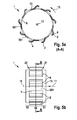
- Fig. 7 shows the above-described tolerance ring 1 according to the prior art.
- the tolerance ring 1 according to the invention is preferably used for shaft-hub connections (not shown). It is particularly preferably provided as an overload protection or for transmitting a torque.
- a vehicle component for example in an adjusting drive (not shown), in particular a tailgate drive, in a shaft-hub connection and takes over there in addition to the tolerance compensation between the shaft and the hub, which cooperate with him, a protection against an externally acting on the shaft-hub connection overload.
Landscapes
- Engineering & Computer Science (AREA)
- General Engineering & Computer Science (AREA)
- Mechanical Engineering (AREA)
- Snaps, Bayonet Connections, Set Pins, And Snap Rings (AREA)
Abstract
Description
- Die vorliegende Erfindung betrifft einen Toleranzring, der aus einem bandförmigen, sich flächig erstreckenden Material mit einer durchgängig geschlossenen Grundfläche hergestellt ist. Die vorliegende Erfindung betrifft weiterhin einen insbesondere erfindungsgemäßen Toleranzring, der sich zylinderförmig um eine Achse erstreckt, mit einem Verformungsbereich, in dem eine Vielzahl Erhebungen angeordnet sind, die gegenüber einer konzentrisch um die Achse angeordneten fiktiven Ringfläche, in der der Toleranzring angeordnet ist, erhaben sind.
- Toleranzringe werden für reibschlüssige Welle- Nabe- Verbindungen verwendet und ermöglichen den Ausgleich von Bearbeitungstoleranzen und Fluchtungsfehlern sowie verschiedene Wärmeausdehnungen zwischen Welle und Nabe. Außerdem ist mit ihnen ein Drehmoment übertragbar. Sie sind auch als Überlastschutz verwendbar, um ein Durchrutschen zwischen Welle und Nabe ab einem definierten Drehmoment zu ermöglichen. Eine Anwendung eines Toleranzrings als Überlastschutz zeigt beispielsweise die Druckschrift
DE 10 2010 038 596 . - Ein Beispiel eines herkömmlichen Toleranzringes zeigt die
Fig. 7 . Der Toleranzring 1 ist aus einem bandförmigen Federstahlblech hergestellt und weist eine zylindrische Form auf, so dass er sich um eine Achse 10 in eine Längsrichtung 11 des Zylinders erstreckt. Im Toleranzring 1 ist ein Spalt 30 vorgesehen, so dass er zwei sich gegenüberliegende offene Enden 31 aufweist. Zudem weist er beidseitig einen unverformten Randbereich 51, 52 auf, der sich konzentrisch um die Achse 10 erstreckt. Mittig weist der Toleranzring 1 einen Verformungsbereich 50 zwischen den Randbereichen 51, 52 auf, in dem in Umfangrichtung 12 verteilt eine Vielzahl zylindrischer Sicken 2 vorgesehen sind. Die Sicken erstrecken sich in Längsrichtung 11 quer zur Bandrichtung und sind an ihren den Randbereichen 51, 52 zugewandten Enden 21, 22 jeweils kugelhalbschalenförmig ausgebildet. Ein solcher Toleranzring 1 weist einen sehr kleinen Federweg auf, so dass er in einem nur sehr kleinen Arbeitsbereich verwendbar ist. Beispielsweise zur Übertragung eines Drehmomentes oder als Überlastschutz erfordert die Verwendung eines solchen Toleranzringes daher die Herstellung des Toleranzringes sowie der mit dem Toleranzring zusammenwirkenden Bauteile mit sehr engen Toleranzen. - Aufgabe der Erfindung ist es, einen Toleranzring zu schaffen, der im Vergleich zum Stand der Technik einen größeren Arbeitsbereich aufweist und daher eine toleranzunabhängigere Herstellung des Toleranzringes und/oder der mit ihm zusammenwirkenden Bauteile ermöglicht.
- Die Aufgabe wird gelöst mit einem Toleranzring, der aus einem bandförmigen, sich flächig erstreckenden Material mit einer durchgängig geschlossenen Grundfläche hergestellt ist, wobei in die Grundfläche gezielt Materialausnehmungen eingebracht sind, die die Federkonstante des Toleranzringes verringern.
- Eine Materialausnehmung im Sinne der Erfindung ist eine Schwächung des Materials, durch die der Toleranzring bei gleicher Federkraft eine geringere Federkonstante aufweist, so dass seine Federkennlinie insgesamt flacher verläuft. Ferner ist eine Materialausnehmung im Sinne der Erfindung eine gezielt vorgesehene Schwächung des Materials, die die Federkonstante des Toleranzringes verringert.
- Prinzipiell eignet sich als Materialausnehmung jede Schwächung, die die gezielte Verringerung der Federkonstante bewirkt. Die Ausführung des Toleranzringes ist nicht auf die ursprüngliche Dicke des verwendeten Ausgangsmaterials beschränkt. Eine Beeinflussung der Federkonstante erfolgt in einer bevorzugten Ausführungsform durch Variation der Dicke des Ausgangsmaterials. Es ist aber besonders bevorzugt, dass die Materialschwächung durch ein Loch gebildet ist. In dieser Ausführungsform ist sie beispielsweise durch Ausstanzen oder Ausschneiden, und daher mit herkömmlichen Verfahren sehr kostengünstig, realisierbar.
- Der Toleranzring erstreckt sich bevorzugt zylinderförmig um eine Achse und in eine Längsrichtung.
- Die Aufgabe wird weiterhin gelöst mit einem insbesondere erfindungsgemäßen Toleranzring, der sich zylinderförmig um eine Achse erstreckt, mit einem Verformungsbereich, in dem eine Vielzahl Erhebungen angeordnet sind, die gegenüber einer konzentrisch um die Achse angeordneten fiktiven Ringfläche, in der der Toleranzring angeordnet ist, erhaben sind, wobei im Verformungsbereich Materialausnehmungen angeordnet sind, die die Federkonstante des Toleranzringes verringern.
- Durch die geringere Federkonstante ist der Federweg bei Belastung mit einer Federkraft größer. Daher ist die Herstellung des Toleranzringes sowie der mit dem Toleranzring zusammenwirkenden Bauteile, insbesondere bei Verwendung des Toleranzringes zur Übertragung eines Drehmomentes oder als Überlastschutz, mit größeren Toleranzen möglich.
- Die Erhebungen sind bevorzugt in einer Umfangsrichtung des Toleranzringes gleichmäßig verteilt angeordnet. Weiterhin bevorzugt erstrecken sich die Erhebungen in Längsrichtung des Toleranzringes. In einer ersten bevorzugten Ausführungsform sind die Materialausnehmungen zwischen den Erhebungen angeordnet. Dabei ist es bevorzugt, dass sie sich in Längsrichtung erstrecken.
- In einer zweiten bevorzugten Ausführungsform sind die Materialausnehmungen zwischen der Grundfläche und der fiktiven Randfläche vorgesehen.
- Durch die Größe, Anzahl und Anordnung der Materialausnehmungen ist die Federkonstante beziehungsweise die Federkennlinie des Toleranzringes einstellbar.
- Es ist bevorzugt, dass der Toleranzring einen ersten Randbereich und einen zweiten Randbereich aufweist, die sich jeweils entlang der fiktiven Ringfläche erstrecken. Im Randbereich ist der Toleranzring daher bevorzugt unverformt und erstreckt sich konzentrisch um die Achse. Der Verformungsbereich ist bevorzugt zwischen den Randbereichen angeordnet.
- In einer weiteren bevorzugten Ausführungsform weisen die Erhebungen jeweils an ihren den Randbereichen zugewandten Seiten die Materialausnehmung auf. Besonders bevorzugt sind die Materialausnehmungen als Loch ausgebildet, so dass die Erhebungen an ihren den Randbereichen zugewandten Seiten offen sind. Besonders bevorzugt sind die Materialausnehmungen im Verformungsbereich und nicht im Randbereich vorgesehen.
- In einer bevorzugten Ausführungsform weist der Toleranzring einen sich in Längsrichtung erstreckenden Spalt auf. Somit weist er zwei offene Enden auf, die sich gegenüber liegen. Die offenen Enden sind bevorzugt, zumindest geringfügig, voneinander beabstandet, so dass der Radius des Toleranzringes veränderbar ist. Dadurch ist er in einem noch größeren Toleranzbereich verwendbar.
- Der Toleranzring ist bevorzugt aus einem Metall oder einer Metalllegierung, insbesondere aus einem Federstahlblech, gefertigt. Besonders bevorzugt ist er einstückig hergestellt. Prinzipiell ist aber auch eine mehrteilige Fertigung denkbar, bei der die mehreren Komponenten des Toleranzringes stoffschlüssig miteinander verbunden sind, insbesondere gelötet oder geschweißt.
- In einer bevorzugten Ausführungsform ist der Toleranzring, insbesondere im Verformungsbereich, wellenförmig ausgebildet.
- Die Aufgabe wird ebenfalls gelöst mit einer Komponente für ein Fahrzeug mit einer Welle- Nabe- Verbindung, die einen erfindungsgemäßen Toleranzring aufweist. Die Fahrzeugkomponente ist bevorzugt ein Heckklappenantrieb. Es sind aber auch andere Fahrzeugkomponenten bevorzugt, bei denen ein Toleranzring insbesondere zur Übertragung eines Drehmomentes oder als Überlastschutz eingesetzt wird. Dies sind bevorzugt Verstellantriebe beispielsweise zum Verstellen eines Sitzes, einer Fahrzeugtür oder eines Schiebedachs. Grundsätzlich ist der erfindungsgemäße Toleranzring aber auch in anderen Komponenten, beispielsweise in Elektrowerkzeugen, in Lenksäulen oder ähnlichen, verwendbar.
- Die Aufgabe wird weiterhin gelöst mit einer Verwendung eines erfindungsgemäßen Toleranzringes für eine Welle- Nabe- Verbindung. Die Aufgabe wird weiterhin gelöst mit einer Verwendung eines erfindungsgemäßen Toleranzringes als Überlastschutz. Die Aufgabe wird weiterhin gelöst mit einer Verwendung eines erfindungsgemäßen Toleranzringes für eine Welle-Nabe- Verbindung mit Überlastschutzfunktion in einem Heckklappenantrieb.
- Die Aufgabe wird weiterhin gelöst mit einem Verfahren zur Herstellung eines erfindungsgemäßen Toleranzringes aus einem bandförmigen, sich flächig erstreckenden Material mit durchgängig geschlossener Grundfläche, wobei
- In einem Verformungsbereich des Toleranzringes Erhebungen in die Grundfläche eingebracht werden, und
- Das bandförmige Material um eine Welle gebogen wird, wobei
- Vor, während oder nach Einbringen der Erhebungen, oder nach dem Biegen des bandförmigen Materials um die Welle, gezielt Materialausnehmungen in den Verformungsbereich eingebracht werden, die die Federkonstante des Toleranzringes verringern.
- Im Folgenden wird die Erfindung anhand von Figuren beschrieben. Die Figuren sind lediglich beispielhaft und schränken den allgemeinen Erfindungsgedanken nicht ein.
- Fig. 1 - 5
- zeigen verschiedene Ausführungsformen erfindungsgemäßer Toleranzringe,
- Fig. 6
- zeigt schematisch die Federkennlinie eines erfindungsgemäßen Toleranzringes im Vergleich zur Federkennlinie eines Toleranzringes gemäß dem Stand der Technik, und
- Fig. 7
- zeigt einen Toleranzring gemäß dem Stand der Technik.
-
Fig. 1 zeigt einen erfindungsgemäßen Toleranzring 1 in perspektivischer Ansicht. - Der Toleranzring 1 ist zylinderförmig ausgebildet und erstreckt sich um eine Achse 10 in eine Längsrichtung 11. Er ist aus einem bandförmigen, sich flächig erstreckenden Material, insbesondere aus Federstahlblech, hergestellt, welches eine durchgängig geschlossene Grundfläche 13 aufweist. Anstelle Federstahlblechs sind auch andere Materialien, insbesondere Metalle oder Metalllegierungen, für die Herstellung des Toleranzringes 1 verwendbar.
- Zur Herstellung des Toleranzringes 1 wird das bandförmige Material in einem Verformungsbereich 50 verformt, wobei vor dem Verformen, während des Verformens oder danach gezielt Materialausnehmungen 4, hier in Form von Löchern, in das Material eingebracht werden, um die Federkonstante KF2 (siehe
Fig. 6 ) des Toleranzringes 1 zu verringern. Anschließend wird das bandförmige Material um eine Welle (nicht gezeigt), die sich entlang der Achse 10 erstreckt, gebogen. Es ist auch ein gezieltes Einbringen der Materialausnehmungen 4 nach dem Biegen des bandförmigen Materials um die Welle denkbar. Dabei entspricht die Erstreckungsrichtung des bandförmigen Materials bevorzugt einer Umfangsrichtung 12 der Welle. - In allen gezeigten Ausführungsformen sind die Materialausnehmungen 4 als Löcher ausgebildet. Daher werden die Begriffe Materialausnehmung 4 und Loch im Folgenden synonym verwendet.
- In der in
Fig. 1 dargestellten Ausführungsform sind im Verformungsbereich eine Vielzahl Erhebungen 2 angeordnet, die sich in Längsrichtung 11 erstrecken. Prinzipiell sind aber auch Toleranzringe 1 denkbar, bei denen sich die Erhebungen 2 in einem Winkel zur Längsrichtung 11 erstrecken. Die Erhebungen 2 sind in Umfangsrichtung 12 des Toleranzringes 1 gleichmäßig verteilt angeordnet. - In der Ausführungsform der
Fig. 1 sind die Erhebungen 2 ferner durchweg in eine der Achse 10 abgewandte Richtung, also nach außen, gerichtet. Es sind aber auch Ausführungsformen bevorzugt, in denen sich die Erhebungen 2 im Verformungsbereich 50 in die der Achse 10 abgewandte und/oder eine der Achse 10 zugewandte Richtung erstrecken, also sowohl nach außen als auch nach innen, oder nur nach innen. Dadurch stützt sich der Toleranzring 1 an dem Bauteil (nicht gezeigt) ab, welches der Achse 10 abgewandt und/oder zugewandt ist, also beispielsweise an einer der Achse 10 abgewandten Nabe oder einer der Achse 10 zugewandten Welle oder sowohl an der Nabe als auch der Welle. - Im Toleranzring 1 ist ein Spalt 30 vorgesehen, so dass er zwei sich gegenüberliegende offene Enden 31 aufweist, die voneinander beabstandet sind. Dadurch ist ein Radius des Toleranzringes 1 geringfügig änderbar. Der Spalt 30 erstreckt sich ebenfalls in die Längsrichtung 11.
- Beidseitig des Verformungsbereiches 50 weist der Toleranzring 1 der
Fig. 1 jeweils einen Randbereich 51, 52 auf, in dem er nicht verformt ist, so dass er sich in den Randbereichen 51, 52 konzentrisch um die Achse 10 erstreckt. - Die Materialausnehmungen 4 sind jeweils an der den Randbereichen 51, 52 zugewandten Seite 21, 22 der Erhebungen 2 angeordnet.
- Der Toleranzring 1 ist in einer fiktiven Ringfläche 6 angeordnet, die sich konzentrisch um die Achse 10 erstreckt. Dabei erstrecken sich die Randbereiche 51, 52 entlang der fiktiven Ringfläche 6. Dadurch sind die Erhebungen 2 gegenüber der Ringfläche 6 erhaben. Im der vorliegenden Ausführungsform sind die Löcher 4 so vorgesehen, dass sie jeweils an den den Randbereichen 51, 52 zugewandten Seiten 21, 22 der Erhebungen 2 zwischen der Ringfläche 6 und der Grundfläche 13 angeordnet sind.
- Der Toleranzring 1 ist hier einstückig gefertigt, bevorzugt als Stanzbiegeteil. Prinzipiell ist er aber auch mehrteilig herstellbar, indem beispielsweise die Randbereiche 51, 52 und der Verformungsbereich 50 separat gefertigt und anschließend stoffschlüssig miteinander verbunden werden, insbesondere durch Schweißen. Dies gilt für alle dargestellten Toleranzringe 1.
-
Fig. 2 zeigt eine weitere Ausführungsform eines erfindungsgemäßen Toleranzringes, und zwar inFig. 2(a) in einer perspektivischen Ansicht, inFig. 2(b) in einer Draufsicht und inFig. 2(c) einen Ausschnitt C aus derFig. 2(b) . - Im Gegensatz zur Ausführungsform der
Fig. 1 weist der Toleranzring 1 derFig. 2 im Verformungsbereich 50 sich in Längsrichtung 11 erstreckende Löcher 4 auf, sowie sich in Längsrichtung 11 erstreckende, unverformte Bereiche 501. Die Löcher 4 sowie die unverformten Bereiche 501 sind zwischen den Erhebungen 2 angeordnet. Sie sind zwischen den Erhebungen 2 so vorgesehen, dass sie sich bis zu den den Randbereichen 51, 52 zugewandten Seiten 21, 22 der Erhebungen 2 erstrecken, so dass auch hier Löcher 4 zwischen der Ringfläche 6 und der Grundfläche 13 angeordnet sind. - Die übrigen Ausführungen für den Toleranzring 1 der
Fig. 1 gelten auch für den Toleranzring 1 derFig. 2 . -
Fig. 3 zeigt eine weitere Ausführungsform eines erfindungsgemäßen Toleranzringes 1 in einer perspektivischen Darstellung. Der Toleranzring 1 weist welleförmige Erhebungen auf, so dass er insgesamt wellenförmig ausgebildet ist. Im Gegensatz zu den Ausführungsformen derFig. 1 und2 weist er keine Randbereiche 51, 52 auf. - Der Toleranzring 1 ist in der fiktiven Ringfläche 6 angeordnet, so dass die Erhebungen 2 gegenüber der fiktiven Ringfläche 6 erhaben sind.
- Zwischen der fiktiven Ringfläche 6 und seiner Grundfläche 13 sind gleichmäßig in Umfangsrichtung 12 verteilt Löcher 4 im Toleranzring 1 vorgesehen. Bei diesem Toleranzring 1 ist die Federkonstante KF2 durch die Amplitude A und Wellenlänge λ der gezielt in den Verformungsbereich 50 eingebrachten wellenförmigen Erhebungen 2 bestimmt.
- Anstelle des Spaltes 30 mit den sich gegenüberliegenden offenen Enden 31 sind diese in der Ausführungsform der
Fig. 3 stoffschlüssig miteinander verbunden, insbesondere durch eine Schweißnaht 35. -
Fig. 4 zeigt eine weitere Ausführungsform eines erfindungsgemäßen Toleranzringes 1, und zwar inFig. 4(a) in einer Draufsicht und inFig. 4(b) in einer Seitenansicht. - Der Toleranzring 1 der
Fig. 4 weist beidseitig des Verformungsbereiches 580 jeweils einen Randbereich 51, 52 auf, in dem er unverformt ist und sich daher konzentrisch um die Achse 10 erstreckt. Im Verformungsbereich 50 sind die Erhebungen 2 angeordnet, die gegenüber der fiktiven Ringfläche 6, in der der Toleranzring 1 angeordnet ist, erhaben sind. Außerdem weist dieser Toleranzring 1 unverformte Bereiche 501 im Verformungsbereich 50 auf. - Die Löcher 4 sind an den den Randbereichen 51, 52 zugewandten Seiten 21, 22 der Erhebungen 2 angeordnet und zwischen der fiktiven Ringfläche 6 und der Grundfläche 13 vorgesehen. In der vorliegenden Ausführungsform erstrecken sie sich von einem unverformten Bereich 501 des Verformungsbereiches 50 zum nächsten unverformten Bereich 501 in Umfangsrichtung 12.
- Dieser Toleranzring 1 weist auch einen Spalt 30 mit sich gegenüberliegenden offenen Enden 31 auf.
-
Fig. 5 zeigt eine weitere Ausführungsform eines erfindungsgemäßen Toleranzringes 1, und zwar inFig. 5(a) in einer Draufsicht und inFig. 5(b) in einer Seitenansicht. - Der Toleranzring 1 der
Fig. 5 weist die den Verformungsbereich 50 begrenzenden Randbereiche 51, 52 auf, aber keinen Spalt 30. Die Löcher 4 erstrecken sich im Verformungsbereich 50 in Längsrichtung 11 zwischen den Randbereichen 51, 52. Zudem erstrecken sie sich auch an den den Randbereichen 51, 52 zugewandten Seiten 21, 22 quer zur Längsrichtung 11. Zwischen den Erhebungen 2 sind auch hier unverformte Bereiche 501 im Verformungsbereich 50 vorgesehen. - Es ist aber auch eine Ausführungsform des Toleranzringes 1 der
Fig. 5 mit einem Spalt 30 bevorzugt. -
Fig. 6 zeigt beispielhaft die Federkennlinie KF2 eines erfindungsgemäßen Toleranzringes 1 im Vergleich zur Federkennlinie KF1 eines Toleranzringes 1 gemäß dem Stand der Technik (s.Fig. 7 ). Auf der horizontalen Achse ist der Federweg 100 aufgetragen, auf der vertikalen Achse die Federkraft 101. - Die Federkonstante ergibt sich aus dem Verhältnis der Federkraft F zu dem Federweg S1, S2, um den sich der Toleranzring 1 bei dieser auf ihn in eine Richtung wirkenden Federkraft F verformt.
- Die hier dargestellten Federkennlinien KF1, KF2 zeigen einen linearen Verlauf, so dass sich die Federkonstanten dieser Toleranzringe 1 bei sich ändernder auf die Toleranzringe 1 wirkender Kraft F nicht ändern. Im Rahmen dieser Ausführungsformen werden daher die Federkonstanten mit denselben Bezugszeichen wie die Federkennlinien KF1, KF2 bezeichnet. Erfindungsgemäße Toleranzringe 1 sind aber auch so herstellbar, dass ihre Federkennlinien KF2 einen nichtlinearen Verlauf zeigen, so dass sich die Federkonstante mit steigender auf den Toleranzring 1 wirkender Federkraft F ändert.
- Der herkömmliche Toleranzring 1 weist eine Federkennlinie KF1 mit einem steileren Verlauf im Vergleich zum erfindungsgemäßen Toleranzring 1 auf, so dass die Federkonstante KF1 des herkömmlichen Toleranzringes 1 größer ist, als die des erfindungsgemäßen Toleranzringes 1. Bei gleicher auf den Toleranzring 1 wirkender Federkraft F ist der Federweg S1, um den sich daher der herkömmliche Toleranzring 1 gegen seine Rückstellkraft verformt, kleiner gegenüber dem Federweg S2 des erfindungsgemäßen Toleranzringes 1.
- Da der erfindungsgemäße Toleranzring 1 sich gegenüber dem herkömmlichen Toleranzring 1 bei gleicher auf ihn wirkender Federkraft F um einen größeren Federweg S2 verformt, ist er in einem größeren Arbeitsbereich einsetzbar.
-
Fig. 7 zeigt den oben beschriebenen Toleranzring 1 gemäß dem Stand der Technik. - Der erfindungsgemäße Toleranzring 1 findet bevorzugt Verwendung für Welle- Nabe- Verbindungen (nicht gezeigt). Besonders bevorzugt wird er als Überlastschutz oder zur Übertragung eines Drehmomentes vorgesehen.
- In einer ganz besonders bevorzugten Ausführungsform ist er in einer Fahrzeugkomponente (nicht gezeigt), beispielsweise in einem Verstellantrieb (nicht gezeigt), insbesondere einem Heckklappenantrieb, in einer Welle- Nabe- Verbindung vorgesehen und übernimmt dort neben dem Toleranzausgleich zwischen der Welle und der Nabe, die mit ihm zusammenwirken, einen Schutz vor einer von außen auf die Welle- Nabe- Verbindung wirkenden Überlast.
Claims (15)
- Toleranzring (1), der aus einem bandförmigen, sich flächig erstreckenden Material mit einer durchgängig geschlossenen Grundfläche (13) hergestellt ist,
dadurch gekennzeichnet, dass
in die Grundfläche (13) gezielt Materialausnehmungen (4) eingebracht sind, die die Federkonstante (KF2) des Toleranzringes (1) verringern. - Toleranzring (1) nach Anspruch 1, dadurch gekennzeichnet, dass er sich zylinderförmig um eine Achse (10) und in eine Längsrichtung (11) erstreckt.
- Toleranzring (1), insbesondere nach einem der vorherigen Ansprüche, der sich zylinderförmig um eine Achse (10) erstreckt, mit einem Verformungsbereich (50), in dem eine Vielzahl Erhebungen (2) angeordnet sind, die gegenüber einer konzentrisch um die Achse (10) angeordneten fiktiven Ringfläche (6), in der der Toleranzring (1) angeordnet ist, erhaben sind,
dadurch gekennzeichnet, dass
im Verformungsbereich (50) Materialausnehmungen (4) angeordnet sind, die die Federkonstante (KF2) des Toleranzringes (1) verringern. - Toleranzring (1) nach einem der vorherigen Ansprüche, dadurch gekennzeichnet, dass die Materialausnehmungen (4) zwischen der Grundfläche (13) und der fiktiven Randfläche (6) vorgesehen sind.
- Toleranzring (1) nach einem der vorherigen Ansprüche, dadurch gekennzeichnet, dass er einen ersten Randbereich (51) und einen zweiten Randbereich (52) aufweist, die sich entlang der fiktiven Ringfläche (6) erstrecken.
- Toleranzring (1) nach einem der vorherigen Ansprüche, dadurch gekennzeichnet, dass der Verformungsbereich (50) zwischen den Randbereichen (51, 52) angeordnet ist.
- Toleranzring (1) nach einem der vorherigen Ansprüche, dadurch gekennzeichnet, dass die Materialausnehmungen (4) jeweils an einer den Randbereichen (51, 52) zugewandten Seite (21, 22) der Erhebungen (2) angeordnet sind.
- Toleranzring (1) nach einem der vorherigen Ansprüche, dadurch gekennzeichnet, dass die Erhebungen (2) in einer Umfangsrichtung (13) des Toleranzringes (1) gleichmäßig verteilt angeordnet sind.
- Toleranzring (1) nach einem der vorherigen Ansprüche, dadurch gekennzeichnet, dass sich die Erhebungen (2) in Längsrichtung (11) des Toleranzringes (1) erstrecken.
- Toleranzring (1) nach einem der vorherigen Ansprüche, dadurch gekennzeichnet, dass sich die Materialausnehmungen (4) in Längsrichtung (11) erstrecken und zwischen den Erhebungen (2) angeordnet sind.
- Toleranzring (1) nach einem der vorherigen Ansprüche, dadurch gekennzeichnet, dass er einen sich in Längsrichtung (11) erstreckenden Spalt (30) aufweist, so dass er zwei offene Enden (31) aufweist, die sich gegenüber liegen.
- Toleranzring (1) nach einem der vorherigen Ansprüche, dadurch gekennzeichnet, dass er einstückig gefertigt ist.
- Komponente für ein Fahrzeug, insbesondere Heckklappenantrieb, mit einer Welle- Nabe- Verbindung, die einen Toleranzring (1) nach einem der vorherigen Ansprüche aufweist.
- Verwendung eines Toleranzringes (1) nach einem der vorherigen Ansprüche für eine Welle- Nabe- Verbindung, insbesondere als Überlastschutz.
- Verfahren zur Herstellung eines Toleranzringes (1) nach einem der vorherigen Ansprüche aus einem bandförmigen, sich flächig erstreckenden Material mit durchgängig geschlossener Grundfläche (13), wobei• In einem Verformungsbereich (50) des Toleranzringes (1) Erhebungen (2) in die Grundfläche (13) eingebracht werden, und• Das bandförmige Material um eine Welle gebogen wird,dadurch gekennzeichnet, dass• vor, während oder nach Einbringen der Erhebungen (2), oder nach dem Biegen des bandförmigen Materials um die Welle, gezielt Materialausnehmungen (4) in den Verformungsbereich (50) eingebracht werden, die die Federkonstante (KF2) des Toleranzringes (1) verringern.
Applications Claiming Priority (1)
| Application Number | Priority Date | Filing Date | Title |
|---|---|---|---|
| DE102011077361A DE102011077361A1 (de) | 2011-06-10 | 2011-06-10 | Feder für eine Welle-/ Nabeverbindung mit Überlastschutzfunktion, insbesondere für Heckklappenantriebe |
Publications (3)
| Publication Number | Publication Date |
|---|---|
| EP2532907A2 true EP2532907A2 (de) | 2012-12-12 |
| EP2532907A3 EP2532907A3 (de) | 2013-11-06 |
| EP2532907B1 EP2532907B1 (de) | 2018-12-12 |
Family
ID=46245870
Family Applications (1)
| Application Number | Title | Priority Date | Filing Date |
|---|---|---|---|
| EP12170683.2A Active EP2532907B1 (de) | 2011-06-10 | 2012-06-04 | Feder für eine Welle-/ Nabeverbindung mit Überlastschutzfunktion, insbesondere für Heckklappenantriebe |
Country Status (2)
| Country | Link |
|---|---|
| EP (1) | EP2532907B1 (de) |
| DE (1) | DE102011077361A1 (de) |
Cited By (8)
| Publication number | Priority date | Publication date | Assignee | Title |
|---|---|---|---|---|
| WO2014207219A1 (en) * | 2013-06-27 | 2014-12-31 | Saint-Gobain Performance Plastics Rencol Ltd. | Tolerance ring with divided torque slip |
| WO2014207061A1 (en) * | 2013-06-27 | 2014-12-31 | Saint-Gobain Performance Plastics Rencol Ltd. | Tolerance ring with locking feature |
| WO2017026274A1 (ja) * | 2015-08-07 | 2017-02-16 | 株式会社東郷製作所 | 軸継手構造 |
| WO2017026273A1 (ja) * | 2015-08-07 | 2017-02-16 | 株式会社東郷製作所 | トレランスリング |
| EP3130813A3 (de) * | 2015-08-14 | 2017-03-01 | Carl Freudenberg KG | Anordnung zur übertragung von drehmoment |
| CN108025941A (zh) * | 2015-09-18 | 2018-05-11 | 维苏威法国股份有限公司 | 输送辊组件、扭矩传递和支撑装置以及制造在高温环境中使用的输送辊组件的方法 |
| CN113137442A (zh) * | 2021-05-07 | 2021-07-20 | 江苏久祥汽车电器集团有限公司 | 一种电池缓冲结构 |
| WO2023273304A1 (zh) * | 2021-06-30 | 2023-01-05 | 徐州南普机电科技有限公司 | 一种可变转矩式过载保护装置及其防过载电机 |
Families Citing this family (6)
| Publication number | Priority date | Publication date | Assignee | Title |
|---|---|---|---|---|
| KR101635729B1 (ko) * | 2012-04-30 | 2016-07-05 | 생-고뱅 퍼포먼스 플라스틱스 렌콜 리미티드 | 슬롯형 측벽을 가지는 공차링 |
| PL2845194T3 (pl) * | 2012-04-30 | 2019-06-28 | Saint-Gobain Performance Plastics Rencol Limited | Pierścień osadczy z perforowanymi falami |
| DE102013204617A1 (de) * | 2013-03-15 | 2014-09-18 | Robert Bosch Gmbh | Welle- Nabe Verbindung, insbesondere Überlastschutz |
| DE102017205393A1 (de) * | 2017-03-30 | 2018-10-04 | Audi Ag | Rotor für eine elektrische Maschine |
| KR102391052B1 (ko) | 2017-04-21 | 2022-04-28 | 생-고뱅 퍼포먼스 플라스틱스 렌콜 리미티드 | 구성 요소 고정 제어를 위한 공차 링, 방법 및 어셈블리 |
| JP7376232B2 (ja) * | 2018-12-07 | 2023-11-08 | 株式会社東郷製作所 | トレランスリング |
Citations (1)
| Publication number | Priority date | Publication date | Assignee | Title |
|---|---|---|---|---|
| DE102010038596A1 (de) | 2010-07-29 | 2012-02-02 | Robert Bosch Gmbh | Verstellantrieb mit integriertem Überlastschutz |
Family Cites Families (5)
| Publication number | Priority date | Publication date | Assignee | Title |
|---|---|---|---|---|
| US3197243A (en) * | 1961-08-15 | 1965-07-27 | Perfect Circle Corp | Aligning and locking device |
| DE2361218C2 (de) * | 1973-12-08 | 1982-06-03 | Industriewerk Schaeffler Ohg, 8522 Herzogenaurach | Toleranzring aus Blech |
| US4479735A (en) * | 1983-01-13 | 1984-10-30 | Westinghouse Electric Corp. | Shrink fit sleeve for rotating machinery |
| US4981390A (en) * | 1987-03-06 | 1991-01-01 | The Ray Engineering Co., Ltd. | Tolerance ring with retaining means |
| DE102008028371B4 (de) * | 2008-06-13 | 2020-10-08 | Schaeffler Technologies AG & Co. KG | Toleranzring |
-
2011
- 2011-06-10 DE DE102011077361A patent/DE102011077361A1/de not_active Ceased
-
2012
- 2012-06-04 EP EP12170683.2A patent/EP2532907B1/de active Active
Patent Citations (1)
| Publication number | Priority date | Publication date | Assignee | Title |
|---|---|---|---|---|
| DE102010038596A1 (de) | 2010-07-29 | 2012-02-02 | Robert Bosch Gmbh | Verstellantrieb mit integriertem Überlastschutz |
Cited By (24)
| Publication number | Priority date | Publication date | Assignee | Title |
|---|---|---|---|---|
| CN105358854B (zh) * | 2013-06-27 | 2018-01-23 | 圣戈班性能塑料万科有限公司 | 具有锁定特征的公差环 |
| WO2014207061A1 (en) * | 2013-06-27 | 2014-12-31 | Saint-Gobain Performance Plastics Rencol Ltd. | Tolerance ring with locking feature |
| US20150000098A1 (en) * | 2013-06-27 | 2015-01-01 | Saint-Gobain Performance Plastics Rencol Limited | Tolerance ring with locking feature |
| US9074637B2 (en) * | 2013-06-27 | 2015-07-07 | Saint-Gobain Performance Plastics Rencol Limited | Tolerance ring with wave structures having disconnected ends |
| CN105339691A (zh) * | 2013-06-27 | 2016-02-17 | 圣戈班性能塑料万科有限公司 | 具有分割的扭矩滑移的公差环 |
| KR20160020530A (ko) * | 2013-06-27 | 2016-02-23 | 생-고뱅 퍼포먼스 플라스틱스 렌콜 리미티드 | 로킹 특징부를 가지는 공차링 |
| CN105358854A (zh) * | 2013-06-27 | 2016-02-24 | 圣戈班性能塑料万科有限公司 | 具有锁定特征的公差环 |
| JP2016523347A (ja) * | 2013-06-27 | 2016-08-08 | サン−ゴバン パフォーマンス プラスティックス レンコール リミティド | ロック特徴を有するトレランスリング |
| WO2014207219A1 (en) * | 2013-06-27 | 2014-12-31 | Saint-Gobain Performance Plastics Rencol Ltd. | Tolerance ring with divided torque slip |
| US10094426B2 (en) | 2013-06-27 | 2018-10-09 | Saint-Gobain Performance Plastics Rencol Limited | Tolerance ring with divided torque slip |
| CN105339691B (zh) * | 2013-06-27 | 2018-09-07 | 圣戈班性能塑料万科有限公司 | 具有分割的扭矩滑移的公差环 |
| CN107709814B (zh) * | 2015-08-07 | 2020-06-23 | 株式会社东乡制作所 | 公差环 |
| JP2017036784A (ja) * | 2015-08-07 | 2017-02-16 | 株式会社東郷製作所 | トレランスリング |
| CN107709814A (zh) * | 2015-08-07 | 2018-02-16 | 株式会社东乡制作所 | 公差环 |
| WO2017026273A1 (ja) * | 2015-08-07 | 2017-02-16 | 株式会社東郷製作所 | トレランスリング |
| JP2017036785A (ja) * | 2015-08-07 | 2017-02-16 | 株式会社東郷製作所 | 軸継手構造 |
| WO2017026274A1 (ja) * | 2015-08-07 | 2017-02-16 | 株式会社東郷製作所 | 軸継手構造 |
| US10704608B2 (en) | 2015-08-07 | 2020-07-07 | Togo Seisakusyo Corporation | Shaft coupling structure |
| US11035418B2 (en) | 2015-08-07 | 2021-06-15 | Togo Seisakusyo Corporation | Tolerance ring |
| EP3130813A3 (de) * | 2015-08-14 | 2017-03-01 | Carl Freudenberg KG | Anordnung zur übertragung von drehmoment |
| CN108025941A (zh) * | 2015-09-18 | 2018-05-11 | 维苏威法国股份有限公司 | 输送辊组件、扭矩传递和支撑装置以及制造在高温环境中使用的输送辊组件的方法 |
| CN108025941B (zh) * | 2015-09-18 | 2021-05-25 | 维苏威法国股份有限公司 | 输送辊组件、扭矩传递和支撑装置以及制造在高温环境中使用的输送辊组件的方法 |
| CN113137442A (zh) * | 2021-05-07 | 2021-07-20 | 江苏久祥汽车电器集团有限公司 | 一种电池缓冲结构 |
| WO2023273304A1 (zh) * | 2021-06-30 | 2023-01-05 | 徐州南普机电科技有限公司 | 一种可变转矩式过载保护装置及其防过载电机 |
Also Published As
| Publication number | Publication date |
|---|---|
| EP2532907B1 (de) | 2018-12-12 |
| EP2532907A3 (de) | 2013-11-06 |
| DE102011077361A1 (de) | 2012-12-13 |
Similar Documents
| Publication | Publication Date | Title |
|---|---|---|
| EP2532907B1 (de) | Feder für eine Welle-/ Nabeverbindung mit Überlastschutzfunktion, insbesondere für Heckklappenantriebe | |
| EP2398606B1 (de) | Verfahren zur herstellung eines pressgehärteten metallbauteils | |
| EP2531321B1 (de) | Warmnietverbindung | |
| DE102014208003A1 (de) | Planetenträger für ein Planetengetriebe aus verschweißten Teilen | |
| EP3648911B1 (de) | Verfahren zur herstellung einer kühlplatte | |
| EP3153746A1 (de) | Kolbenbolzen | |
| DE112009005483T5 (de) | Elemente eines Riemens für ein stufenlos einstellbares Fahrzeuggetriebe und Verfahren des Herstellens der Elemente | |
| DE112005002006B4 (de) | Induktionshärteverfahren und in einem Induktionshärtevorgang verwendete Vorrichtung | |
| DE102014214743A1 (de) | Ringförmiges Getriebebauteil, insbesondere Hohlrad, mit in Ringform gebogener Laufverzahnung | |
| DE112012002384T5 (de) | Trägerelement | |
| DE102010036277A1 (de) | Kupplungskörper für ein Gangrad eines Schaltgetriebes sowie Gangrad mit Kupplungskörper | |
| WO2015188816A2 (de) | Schaltgabel | |
| EP3269960A1 (de) | Verstellring einer variablen turbinengeometrie | |
| DE102012011020A1 (de) | Stanzniet, Nietverbindung und Nietverfahren | |
| DE102016202005A1 (de) | Nutzfahrzeugrad und Verwendung | |
| DE102015207461B4 (de) | Bauteilanordnung und Verfahren zu deren Herstellung | |
| EP3228402B1 (de) | Verfahren zum herstellen eines wenigstens einen vorsprung aufweisenden bauelements | |
| EP3225889B1 (de) | Laschenverbindung zur verbindung von blechlagen und zylinderkopfdichtung | |
| EP3748191B1 (de) | Optimierte kettenlängensteuerung | |
| DE102009028466A1 (de) | Verfahren zum Vernieten zweier Bauteile, insbesondere Deckscheibenelemente einer Torsionsschwingungsdämpferanordnung, in gegenseitigem Abstand zueinander | |
| DE102008002139A1 (de) | Ausgleichselement | |
| EP4091884A1 (de) | Abschirmbauteil | |
| DE102013214403A1 (de) | Grundplatte für einen Fahrzeugwärmetauscher, Verfahren zu ihrer Herstellung, Wärmetauscher und Ölfiltermodul | |
| DE102019123987A1 (de) | Verfahren zur Herstellung eines Nockenwellenverstellers | |
| DE102019129316A1 (de) | Laschenkette |
Legal Events
| Date | Code | Title | Description |
|---|---|---|---|
| PUAI | Public reference made under article 153(3) epc to a published international application that has entered the european phase |
Free format text: ORIGINAL CODE: 0009012 |
|
| AK | Designated contracting states |
Kind code of ref document: A2 Designated state(s): AL AT BE BG CH CY CZ DE DK EE ES FI FR GB GR HR HU IE IS IT LI LT LU LV MC MK MT NL NO PL PT RO RS SE SI SK SM TR |
|
| AX | Request for extension of the european patent |
Extension state: BA ME |
|
| RAP1 | Party data changed (applicant data changed or rights of an application transferred) |
Owner name: FEDERTECHNIK WANGS AG Owner name: ROBERT BOSCH GMBH |
|
| PUAL | Search report despatched |
Free format text: ORIGINAL CODE: 0009013 |
|
| AK | Designated contracting states |
Kind code of ref document: A3 Designated state(s): AL AT BE BG CH CY CZ DE DK EE ES FI FR GB GR HR HU IE IS IT LI LT LU LV MC MK MT NL NO PL PT RO RS SE SI SK SM TR |
|
| AX | Request for extension of the european patent |
Extension state: BA ME |
|
| RIC1 | Information provided on ipc code assigned before grant |
Ipc: F16D 1/08 20060101AFI20130927BHEP |
|
| 17P | Request for examination filed |
Effective date: 20140506 |
|
| RBV | Designated contracting states (corrected) |
Designated state(s): AL AT BE BG CH CY CZ DE DK EE ES FI FR GB GR HR HU IE IS IT LI LT LU LV MC MK MT NL NO PL PT RO RS SE SI SK SM TR |
|
| 17Q | First examination report despatched |
Effective date: 20160401 |
|
| STAA | Information on the status of an ep patent application or granted ep patent |
Free format text: STATUS: EXAMINATION IS IN PROGRESS |
|
| GRAP | Despatch of communication of intention to grant a patent |
Free format text: ORIGINAL CODE: EPIDOSNIGR1 |
|
| STAA | Information on the status of an ep patent application or granted ep patent |
Free format text: STATUS: GRANT OF PATENT IS INTENDED |
|
| INTG | Intention to grant announced |
Effective date: 20180628 |
|
| GRAS | Grant fee paid |
Free format text: ORIGINAL CODE: EPIDOSNIGR3 |
|
| GRAA | (expected) grant |
Free format text: ORIGINAL CODE: 0009210 |
|
| STAA | Information on the status of an ep patent application or granted ep patent |
Free format text: STATUS: THE PATENT HAS BEEN GRANTED |
|
| AK | Designated contracting states |
Kind code of ref document: B1 Designated state(s): AL AT BE BG CH CY CZ DE DK EE ES FI FR GB GR HR HU IE IS IT LI LT LU LV MC MK MT NL NO PL PT RO RS SE SI SK SM TR |
|
| REG | Reference to a national code |
Ref country code: GB Ref legal event code: FG4D Free format text: NOT ENGLISH |
|
| REG | Reference to a national code |
Ref country code: CH Ref legal event code: EP |
|
| REG | Reference to a national code |
Ref country code: AT Ref legal event code: REF Ref document number: 1076425 Country of ref document: AT Kind code of ref document: T Effective date: 20181215 |
|
| REG | Reference to a national code |
Ref country code: DE Ref legal event code: R096 Ref document number: 502012013958 Country of ref document: DE |
|
| REG | Reference to a national code |
Ref country code: IE Ref legal event code: FG4D Free format text: LANGUAGE OF EP DOCUMENT: GERMAN |
|
| REG | Reference to a national code |
Ref country code: NL Ref legal event code: MP Effective date: 20181212 |
|
| REG | Reference to a national code |
Ref country code: LT Ref legal event code: MG4D |
|
| PG25 | Lapsed in a contracting state [announced via postgrant information from national office to epo] |
Ref country code: LT Free format text: LAPSE BECAUSE OF FAILURE TO SUBMIT A TRANSLATION OF THE DESCRIPTION OR TO PAY THE FEE WITHIN THE PRESCRIBED TIME-LIMIT Effective date: 20181212 Ref country code: BG Free format text: LAPSE BECAUSE OF FAILURE TO SUBMIT A TRANSLATION OF THE DESCRIPTION OR TO PAY THE FEE WITHIN THE PRESCRIBED TIME-LIMIT Effective date: 20190312 Ref country code: NO Free format text: LAPSE BECAUSE OF FAILURE TO SUBMIT A TRANSLATION OF THE DESCRIPTION OR TO PAY THE FEE WITHIN THE PRESCRIBED TIME-LIMIT Effective date: 20190312 Ref country code: ES Free format text: LAPSE BECAUSE OF FAILURE TO SUBMIT A TRANSLATION OF THE DESCRIPTION OR TO PAY THE FEE WITHIN THE PRESCRIBED TIME-LIMIT Effective date: 20181212 Ref country code: LV Free format text: LAPSE BECAUSE OF FAILURE TO SUBMIT A TRANSLATION OF THE DESCRIPTION OR TO PAY THE FEE WITHIN THE PRESCRIBED TIME-LIMIT Effective date: 20181212 Ref country code: HR Free format text: LAPSE BECAUSE OF FAILURE TO SUBMIT A TRANSLATION OF THE DESCRIPTION OR TO PAY THE FEE WITHIN THE PRESCRIBED TIME-LIMIT Effective date: 20181212 Ref country code: FI Free format text: LAPSE BECAUSE OF FAILURE TO SUBMIT A TRANSLATION OF THE DESCRIPTION OR TO PAY THE FEE WITHIN THE PRESCRIBED TIME-LIMIT Effective date: 20181212 |
|
| PG25 | Lapsed in a contracting state [announced via postgrant information from national office to epo] |
Ref country code: SE Free format text: LAPSE BECAUSE OF FAILURE TO SUBMIT A TRANSLATION OF THE DESCRIPTION OR TO PAY THE FEE WITHIN THE PRESCRIBED TIME-LIMIT Effective date: 20181212 Ref country code: AL Free format text: LAPSE BECAUSE OF FAILURE TO SUBMIT A TRANSLATION OF THE DESCRIPTION OR TO PAY THE FEE WITHIN THE PRESCRIBED TIME-LIMIT Effective date: 20181212 Ref country code: GR Free format text: LAPSE BECAUSE OF FAILURE TO SUBMIT A TRANSLATION OF THE DESCRIPTION OR TO PAY THE FEE WITHIN THE PRESCRIBED TIME-LIMIT Effective date: 20190313 Ref country code: RS Free format text: LAPSE BECAUSE OF FAILURE TO SUBMIT A TRANSLATION OF THE DESCRIPTION OR TO PAY THE FEE WITHIN THE PRESCRIBED TIME-LIMIT Effective date: 20181212 |
|
| PG25 | Lapsed in a contracting state [announced via postgrant information from national office to epo] |
Ref country code: NL Free format text: LAPSE BECAUSE OF FAILURE TO SUBMIT A TRANSLATION OF THE DESCRIPTION OR TO PAY THE FEE WITHIN THE PRESCRIBED TIME-LIMIT Effective date: 20181212 |
|
| PG25 | Lapsed in a contracting state [announced via postgrant information from national office to epo] |
Ref country code: IT Free format text: LAPSE BECAUSE OF FAILURE TO SUBMIT A TRANSLATION OF THE DESCRIPTION OR TO PAY THE FEE WITHIN THE PRESCRIBED TIME-LIMIT Effective date: 20181212 Ref country code: PT Free format text: LAPSE BECAUSE OF FAILURE TO SUBMIT A TRANSLATION OF THE DESCRIPTION OR TO PAY THE FEE WITHIN THE PRESCRIBED TIME-LIMIT Effective date: 20190412 Ref country code: PL Free format text: LAPSE BECAUSE OF FAILURE TO SUBMIT A TRANSLATION OF THE DESCRIPTION OR TO PAY THE FEE WITHIN THE PRESCRIBED TIME-LIMIT Effective date: 20181212 Ref country code: CZ Free format text: LAPSE BECAUSE OF FAILURE TO SUBMIT A TRANSLATION OF THE DESCRIPTION OR TO PAY THE FEE WITHIN THE PRESCRIBED TIME-LIMIT Effective date: 20181212 |
|
| PG25 | Lapsed in a contracting state [announced via postgrant information from national office to epo] |
Ref country code: EE Free format text: LAPSE BECAUSE OF FAILURE TO SUBMIT A TRANSLATION OF THE DESCRIPTION OR TO PAY THE FEE WITHIN THE PRESCRIBED TIME-LIMIT Effective date: 20181212 Ref country code: RO Free format text: LAPSE BECAUSE OF FAILURE TO SUBMIT A TRANSLATION OF THE DESCRIPTION OR TO PAY THE FEE WITHIN THE PRESCRIBED TIME-LIMIT Effective date: 20181212 Ref country code: IS Free format text: LAPSE BECAUSE OF FAILURE TO SUBMIT A TRANSLATION OF THE DESCRIPTION OR TO PAY THE FEE WITHIN THE PRESCRIBED TIME-LIMIT Effective date: 20190412 Ref country code: SK Free format text: LAPSE BECAUSE OF FAILURE TO SUBMIT A TRANSLATION OF THE DESCRIPTION OR TO PAY THE FEE WITHIN THE PRESCRIBED TIME-LIMIT Effective date: 20181212 Ref country code: SM Free format text: LAPSE BECAUSE OF FAILURE TO SUBMIT A TRANSLATION OF THE DESCRIPTION OR TO PAY THE FEE WITHIN THE PRESCRIBED TIME-LIMIT Effective date: 20181212 |
|
| REG | Reference to a national code |
Ref country code: DE Ref legal event code: R097 Ref document number: 502012013958 Country of ref document: DE |
|
| PLBE | No opposition filed within time limit |
Free format text: ORIGINAL CODE: 0009261 |
|
| STAA | Information on the status of an ep patent application or granted ep patent |
Free format text: STATUS: NO OPPOSITION FILED WITHIN TIME LIMIT |
|
| PG25 | Lapsed in a contracting state [announced via postgrant information from national office to epo] |
Ref country code: DK Free format text: LAPSE BECAUSE OF FAILURE TO SUBMIT A TRANSLATION OF THE DESCRIPTION OR TO PAY THE FEE WITHIN THE PRESCRIBED TIME-LIMIT Effective date: 20181212 Ref country code: SI Free format text: LAPSE BECAUSE OF FAILURE TO SUBMIT A TRANSLATION OF THE DESCRIPTION OR TO PAY THE FEE WITHIN THE PRESCRIBED TIME-LIMIT Effective date: 20181212 |
|
| 26N | No opposition filed |
Effective date: 20190913 |
|
| PG25 | Lapsed in a contracting state [announced via postgrant information from national office to epo] |
Ref country code: MC Free format text: LAPSE BECAUSE OF FAILURE TO SUBMIT A TRANSLATION OF THE DESCRIPTION OR TO PAY THE FEE WITHIN THE PRESCRIBED TIME-LIMIT Effective date: 20181212 |
|
| REG | Reference to a national code |
Ref country code: CH Ref legal event code: PL |
|
| GBPC | Gb: european patent ceased through non-payment of renewal fee |
Effective date: 20190604 |
|
| REG | Reference to a national code |
Ref country code: BE Ref legal event code: MM Effective date: 20190630 |
|
| PG25 | Lapsed in a contracting state [announced via postgrant information from national office to epo] |
Ref country code: TR Free format text: LAPSE BECAUSE OF FAILURE TO SUBMIT A TRANSLATION OF THE DESCRIPTION OR TO PAY THE FEE WITHIN THE PRESCRIBED TIME-LIMIT Effective date: 20181212 |
|
| PG25 | Lapsed in a contracting state [announced via postgrant information from national office to epo] |
Ref country code: GB Free format text: LAPSE BECAUSE OF NON-PAYMENT OF DUE FEES Effective date: 20190604 Ref country code: IE Free format text: LAPSE BECAUSE OF NON-PAYMENT OF DUE FEES Effective date: 20190604 |
|
| PG25 | Lapsed in a contracting state [announced via postgrant information from national office to epo] |
Ref country code: CH Free format text: LAPSE BECAUSE OF NON-PAYMENT OF DUE FEES Effective date: 20190630 Ref country code: LI Free format text: LAPSE BECAUSE OF NON-PAYMENT OF DUE FEES Effective date: 20190630 Ref country code: LU Free format text: LAPSE BECAUSE OF NON-PAYMENT OF DUE FEES Effective date: 20190604 Ref country code: BE Free format text: LAPSE BECAUSE OF NON-PAYMENT OF DUE FEES Effective date: 20190630 |
|
| REG | Reference to a national code |
Ref country code: AT Ref legal event code: MM01 Ref document number: 1076425 Country of ref document: AT Kind code of ref document: T Effective date: 20190604 |
|
| PG25 | Lapsed in a contracting state [announced via postgrant information from national office to epo] |
Ref country code: AT Free format text: LAPSE BECAUSE OF NON-PAYMENT OF DUE FEES Effective date: 20190604 |
|
| PG25 | Lapsed in a contracting state [announced via postgrant information from national office to epo] |
Ref country code: CY Free format text: LAPSE BECAUSE OF FAILURE TO SUBMIT A TRANSLATION OF THE DESCRIPTION OR TO PAY THE FEE WITHIN THE PRESCRIBED TIME-LIMIT Effective date: 20181212 |
|
| PG25 | Lapsed in a contracting state [announced via postgrant information from national office to epo] |
Ref country code: MT Free format text: LAPSE BECAUSE OF FAILURE TO SUBMIT A TRANSLATION OF THE DESCRIPTION OR TO PAY THE FEE WITHIN THE PRESCRIBED TIME-LIMIT Effective date: 20181212 Ref country code: HU Free format text: LAPSE BECAUSE OF FAILURE TO SUBMIT A TRANSLATION OF THE DESCRIPTION OR TO PAY THE FEE WITHIN THE PRESCRIBED TIME-LIMIT; INVALID AB INITIO Effective date: 20120604 |
|
| PG25 | Lapsed in a contracting state [announced via postgrant information from national office to epo] |
Ref country code: MK Free format text: LAPSE BECAUSE OF FAILURE TO SUBMIT A TRANSLATION OF THE DESCRIPTION OR TO PAY THE FEE WITHIN THE PRESCRIBED TIME-LIMIT Effective date: 20181212 |
|
| PGFP | Annual fee paid to national office [announced via postgrant information from national office to epo] |
Ref country code: FR Payment date: 20230622 Year of fee payment: 12 |
|
| PGFP | Annual fee paid to national office [announced via postgrant information from national office to epo] |
Ref country code: DE Payment date: 20230817 Year of fee payment: 12 |