EP2531756B2 - Electrovanne pilote - Google Patents
Electrovanne pilote Download PDFInfo
- Publication number
- EP2531756B2 EP2531756B2 EP11705269.6A EP11705269A EP2531756B2 EP 2531756 B2 EP2531756 B2 EP 2531756B2 EP 11705269 A EP11705269 A EP 11705269A EP 2531756 B2 EP2531756 B2 EP 2531756B2
- Authority
- EP
- European Patent Office
- Prior art keywords
- solenoid valve
- flat
- core
- valve according
- coil
- Prior art date
- Legal status (The legal status is an assumption and is not a legal conclusion. Google has not performed a legal analysis and makes no representation as to the accuracy of the status listed.)
- Active
Links
Images


Classifications
-
- F—MECHANICAL ENGINEERING; LIGHTING; HEATING; WEAPONS; BLASTING
- F16—ENGINEERING ELEMENTS AND UNITS; GENERAL MEASURES FOR PRODUCING AND MAINTAINING EFFECTIVE FUNCTIONING OF MACHINES OR INSTALLATIONS; THERMAL INSULATION IN GENERAL
- F16K—VALVES; TAPS; COCKS; ACTUATING-FLOATS; DEVICES FOR VENTING OR AERATING
- F16K31/00—Actuating devices; Operating means; Releasing devices
- F16K31/02—Actuating devices; Operating means; Releasing devices electric; magnetic
- F16K31/06—Actuating devices; Operating means; Releasing devices electric; magnetic using a magnet, e.g. diaphragm valves, cutting off by means of a liquid
- F16K31/0603—Multiple-way valves
- F16K31/0624—Lift valves
- F16K31/0627—Lift valves with movable valve member positioned between seats
-
- F—MECHANICAL ENGINEERING; LIGHTING; HEATING; WEAPONS; BLASTING
- F16—ENGINEERING ELEMENTS AND UNITS; GENERAL MEASURES FOR PRODUCING AND MAINTAINING EFFECTIVE FUNCTIONING OF MACHINES OR INSTALLATIONS; THERMAL INSULATION IN GENERAL
- F16K—VALVES; TAPS; COCKS; ACTUATING-FLOATS; DEVICES FOR VENTING OR AERATING
- F16K31/00—Actuating devices; Operating means; Releasing devices
- F16K31/02—Actuating devices; Operating means; Releasing devices electric; magnetic
- F16K31/06—Actuating devices; Operating means; Releasing devices electric; magnetic using a magnet, e.g. diaphragm valves, cutting off by means of a liquid
- F16K31/0603—Multiple-way valves
- F16K31/0606—Multiple-way valves fluid passing through the solenoid coil
-
- F—MECHANICAL ENGINEERING; LIGHTING; HEATING; WEAPONS; BLASTING
- F16—ENGINEERING ELEMENTS AND UNITS; GENERAL MEASURES FOR PRODUCING AND MAINTAINING EFFECTIVE FUNCTIONING OF MACHINES OR INSTALLATIONS; THERMAL INSULATION IN GENERAL
- F16K—VALVES; TAPS; COCKS; ACTUATING-FLOATS; DEVICES FOR VENTING OR AERATING
- F16K31/00—Actuating devices; Operating means; Releasing devices
- F16K31/02—Actuating devices; Operating means; Releasing devices electric; magnetic
- F16K31/06—Actuating devices; Operating means; Releasing devices electric; magnetic using a magnet, e.g. diaphragm valves, cutting off by means of a liquid
- F16K31/0644—One-way valve
- F16K31/0651—One-way valve the fluid passing through the solenoid coil
-
- F—MECHANICAL ENGINEERING; LIGHTING; HEATING; WEAPONS; BLASTING
- F16—ENGINEERING ELEMENTS AND UNITS; GENERAL MEASURES FOR PRODUCING AND MAINTAINING EFFECTIVE FUNCTIONING OF MACHINES OR INSTALLATIONS; THERMAL INSULATION IN GENERAL
- F16K—VALVES; TAPS; COCKS; ACTUATING-FLOATS; DEVICES FOR VENTING OR AERATING
- F16K31/00—Actuating devices; Operating means; Releasing devices
- F16K31/02—Actuating devices; Operating means; Releasing devices electric; magnetic
- F16K31/06—Actuating devices; Operating means; Releasing devices electric; magnetic using a magnet, e.g. diaphragm valves, cutting off by means of a liquid
- F16K31/0644—One-way valve
- F16K31/0655—Lift valves
Definitions
- the present invention relates to miniature solenoid valves commonly used in controlling compressed air distribution systems with a slide or flap valve. These miniature solenoid valves act as a multiplier and power controller. Indeed, for a low electrical input power, often less than 1W, the controlled pneumatic output power is greater than 1kW.
- the construction principle of miniature solenoid valves is based on electromagnets whose moving element can have two types of construction.
- the first type of construction is characterized by a cylindrical core, penetrating deep into the central part of a coil belonging to the electromagnet. This construction is commonly called a plunger solenoid valve.
- the second type of construction is characterized by a flat-shaped core, which does not penetrate into the central part of the coil.
- This construction is commonly called a flat moving core solenoid valve.
- a solenoid valve comprising a retaining ring made of magnetic material, inserted into the body of the solenoid valve.
- US 5,374,029 describes a solenoid valve comprising a movable core inside a ring made of magnetic material, used to loop back the magnetic flux.
- a non-magnetic ring is interposed between the coil and this magnetic ring.
- the distance traveled by the flat moving core between its two stable positions is called its stroke.
- the core stroke depends on the dimensions of a large number of parts, but also on the variability of the spring operating points depending on the characteristics of the electromagnet's magnetic forces. This makes it very difficult to produce miniature solenoid valves with a reproducible flow rate value and to guarantee low power consumption.
- the present invention aims, in particular, to propose a miniature solenoid valve with low absorbed power, the moving element of which can be likened to a flat moving core and the stroke and return force of this flat moving core of which can be better controlled, so that the flow rate value is reproducible.
- the solenoid valve comprises all the characteristics of claim 1.
- the flat spring associated with a retaining ring, allows the adjustment of a pre-load force used to seal a supply orifice when the valve is in the rest position, independently of the adjustment of the stroke of the flat movable core.
- the adjustment of the stroke of the flat moving core can be obtained when setting up the subassembly consisting of the coil and the fixed core.
- the feed port and the usage port(s) can be made in the lower part of the body.
- the retaining ring can allow the centering of the fixed core.
- the feed orifice and the use orifice(s) can be made in the bottom, integral with the body.
- the coil body may have several bosses.
- the valve can have a polygonal shape.
- the valve may be cylindrical in shape, with a shoulder in the flat moving core acting as a retainer.
- the valve may have a shoulder.
- a conical spring can be inserted between the shoulder of the valve and the shoulder of the flat moving core.
- a centering washer in association with the flat preload spring, can center and guide the flat moving core, while limiting friction due to the very low thickness of the centering washer.
- This centering washer can be replaced by a second flat spring, of low stiffness, pre-stressed by means of a shoulder in the body allowing the flat mobile core, in association with the flat return spring, to be guided without any friction, neither with the body nor with any other part. internal.
- the flat moving core and the fixed core may have a near-air-gap area with a stepped geometry.
- the outer diameter of the flat movable core can be reduced so as to limit its mass and in that said flat movable core has a bead replacing the guide washer.
- the centering function of the flat mobile core is then obtained, not by a centering washer, but by the bead made directly on the outer diameter of the flat mobile core.
- the external shape of the body section may be truncated on at least two opposite faces, thus forming flats.
- the sealing of the fluid circuit of the solenoid valve with respect to the exterior can be obtained, depending on the construction, by O-rings integrated into the pilot solenoid valve, or by gaskets forming an integral part of the device or apparatus receiving the pilot solenoid valve.
- all the fluid channels connecting the solenoid valve to the external devices are rectilinear and therefore do not present any sudden change in direction of the fluid, hence the absence of additional localized pressure losses, so the air flow is maximum for a low pressure difference.
- the flat moving core used has a particular shape that allows for a force characteristic to be achieved depending on the position adopted, through the influence of the geometric parameters of the air gaps. This shape allows for the magnetic air gap to be reduced without changing the useful stroke and for the attraction characteristic of this flat moving core to be modified.
- the optimization of the resulting dynamic force is also achieved by minimizing the volume, and therefore the mass, of the flat moving core.
- the variability of the operating points of the flat spring is limited by an "in situ" adjustment of the latter, guaranteeing the value of the low absorbed power.
- the miniature solenoid valve according to the invention may also include a one-piece structure of the body connecting the electromagnetic part to the fluidic part, here pneumatic.
- a one-piece structure of the body connecting the electromagnetic part to the fluidic part here pneumatic.
- the flow rate of the feed port is directly controlled by the position of the flat moving core element of the electromagnetic and pneumatic system.
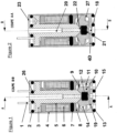
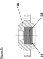
- the magnetic part of the solenoid valve allowing the looping of the magnetic flux generated by the coil 17, is composed of a body 4, a fixed core 3 and a flat mobile core 10 made of ferromagnetic material.
- the flat moving core 10 moves along the main axis of the solenoid valve between the fixed core 3 and the lower part of the body 4.
- the flat moving core 10 which moves along the main axis of the solenoid valve is subjected to an elastic return force due to the flat spring 9. This force, adjustable during assembly, is called pre-load.
- the fluidic part of the solenoid valve is composed of the body 4, the fixed core 3 and the flat movable core 10 comprising a double-sided valve 12.
- the fluidic part of the solenoid valve allows the control of the air flow rates from the supply port 18 to the use port(s) 19 or from the use port(s) 19 to the exhaust port 20.
- An alternative construction consists of controlling the passage of the fluid only between the supply port 18 and use port 19.
- the sealing of the fluid circuit of the solenoid valve is obtained on the one hand by an oblong seal 7 trapped between the coil frame 5 and a retaining ring 8 ensuring internal sealing, and on the other hand by the four O-rings 2, 13, 15 and 26 ensuring external sealing.
- This external sealing function can also be achieved by one or more external gaskets (not shown), forming an integral part of the apparatus or device receiving the pilot solenoid valve, and thereby replacing one or more O-rings 2, 13, 15 and 26.
- the retaining ring 8 is made of non-magnetic material so as not to influence the characteristics of the magnetic field.
- the feed orifice 18 and the use orifice(s) 19 are made in the lower part of the body 4 called the bottom 4D.
- the bottom 4D is integral with the body 4. This makes it possible in particular to limit assembly dispersions and thereby to achieve more precise adjustment of the position of the ring 8 and the travel of the flat movable core 10.
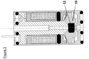
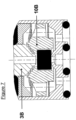
- FIG. 3 illustrates the solenoid valve under tension.
- the core 10 fitted with the valve 12 is then in the high position, and in abutment on the fixed core 3. In this way the exhaust orifice 20 is closed by the action of the valve 12 on the seat 22.
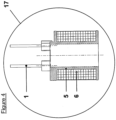
- the coil 17 is composed of a coil frame 5, a winding 6 and two electrical connection pins 1.
- the coil 17, an oblong seal 7 and the fixed core 3 form a coil subassembly 30 whose constitution is more particularly illustrated Figure 5 .
- the coil 17 is slid along the axis of the fixed core 3 until it comes into abutment on it.
- the oblong seal 7 is mounted on the fixed core 3 so as to retain the coil 17 on the fixed core 3.
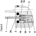
- connection area of the coil subassembly 30 is more particularly visible Figure 6 .
- the connection pins 1 and their supports 24 provided in the coil frame 5 pass through the fixed core 3 via two through holes 25 provided for this purpose.
- a resin 16 can be injected between the fixed core 3 and the coil frame 5, in order to secure the coil 17 and the fixed core 3. This operation is carried out after insertion of the coil subassembly 30 into the body 4.
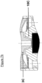
- FIG. 7 illustrates an alternative embodiment 10B of the shape of the flat moving core 10.
- the aim here is to achieve a particular magnetic force characteristic between the flat moving core 10B and the end of the fixed core 3B.
- particular geometries are used in the areas close to the motor air gap.
- the magnetic flux is in fact more marked for a conical shape ( Figure 1 ) or stepped ( Figure 7 ), allowing an identical attraction characteristic for reduced electrical energy consumption.
- the efficiency of the electromagnet in the vicinity of the working air gap is higher using one or the other of these two geometries.
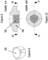
- valve 12 illustrated in Figure 8
- This polygonal-shaped valve 12 is inserted into a circular bore in the flat movable core 10.
- This particular polygonal shape, inserted into a circular hole advantageously makes it possible to maintain the valve in its housing, while preventing any deformation of the bearing surfaces on the seats 21, 22 and ensuring the clearance of any burrs relating to the closing of the valve mold.
- valve 12B may be cylindrical in shape, with a shoulder 34 in the flat movable core 10D then acting as a retainer. This option is illustrated in Figure 9b .
- valve 12C Another geometry of the valve 12C, showing a shoulder 35, can also be produced, so as to obtain greater flexibility of the valve 12C inside the flat movable core 10E, making it possible to promote contact between the flat movable core 10E and the fixed core 3 when the coil 17 is energized. This option is illustrated in Figure 9c .
- the design of the solenoid valve allows the mounting of all the internal components from the rear of the body 4, via an opening 23 particularly suitable for the insertion of the flat movable core 10, the fixed core 3 and the coil 17.
- the design of the solenoid valve also allows the independent adjustment of the stroke and the pre-load. The mounting of the various elements of the solenoid valve is explained below.
- the centering washer 11 and the flat movable core assembly 10, 12 are placed in the lower part of the body 4.
- the flat spring 9 is then inserted and comes into contact with the flat movable core assembly 10, 12.
- the retaining ring 8 is inserted into the body 4 until it makes contact with the flat spring 9.
- the flat spring 9 exerts the preload on the flat movable core assembly 10, 12 and the flat movable core assembly 10, 12 comes into contact with the feed orifice 18.
- the preload force is then checked by a suitable means.
- the retaining ring 8 When the position of the retaining ring 8 is such that the preload force reaches a predefined correct value, the retaining ring 8 is crimped onto the body 4.
- the coil subassembly 30 is then inserted into the body 4 to a position such that the stroke reaches a satisfactory value.
- the value of the stroke is checked by alternating positions between the rest position, coil not powered, and the actuated position, coil powered, so that the stroke is defined with an accuracy of the order of a few tens of micrometers.
- the retaining ring 8 also has the function of centering the lower part of the fixed core 3, relative to the flat mobile core 10, when inserting the coil subassembly 30 into the body 4.
- the body 4 and the coil subassembly 30 are then crimped through the fixed core 3 in the upper part of the solenoid valve.
- the supply orifice 18 is closed by the valve 12, thanks to the preload exerted by the flat spring 9 on the flat movable core 10 making it possible to maintain a force on the seat 21 of the supply orifice 18, necessary to ensure the isolation of the latter from the other orifices 19 and 20.
- the use orifice(s) 19 and the exhaust orifice 20 are then connected, via one or more connecting orifice(s) 14 of the flat movable core 10. Note that the flat spring 9 as well as the centering washer 11 are sufficiently perforated so as not to disturb the passage of the fluid.
- the flat moving core 10 In the actuated position, with the coil powered, the flat moving core 10 is magnetically attracted by the fixed core 3 until contact between these two parts, called bonding.
- the exhaust orifice 20 is then closed by the valve 12.
- the pressure exerted on the latter by the compressed air coming from the supply orifice 18 makes it possible to maintain a force on the seat 22 of the exhaust orifice 20, necessary to ensure the isolation of the latter from the other orifices 18 and 19.
- the supply orifice 18 and the use orifice(s) 19 are then connected.
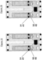
- FIGS 11 to 14 illustrate examples of the embodiment of body 4, the lateral faces of which can be truncated on two opposite faces ( Figures 13 and 14 ) or on four sides ( Figures 11 and 12 ). The side faces then become flats.
- the localized reduction in the thickness of the body 4 thus caused allows the optimization of the crimping operations of the coil subassembly 30 and the body 4 as well as the holding ring 8 with this same body 4, while maintaining a necessary and sufficient section of magnetic material in the thick zones in order to ensure the circulation of the magnetic flux without saturation.
- These embodiments also make it possible to limit the lateral size of the product in at least one direction.
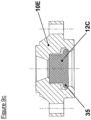
- FIGS. 15 and 16 illustrate alternative embodiments relating to the use of the oblong-shaped seal 7, ensuring the internal sealing of the product.
- This oblong seal 7 is then replaced by two O-rings 31 and 32, the respective housings 41 and 42 of which are made either in the coil frame 5 ( Figure 15 ), or in the retaining ring 8 ( Figure 16 ).
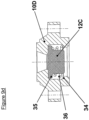
- FIG. 17 illustrates an alternative embodiment 4C of the body 4 and 10C of the flat movable core 10.
- the outer diameter of the flat movable core 10C is reduced, in order to further limit the impact of the mass of this flat movable core 10C on the performance of the product.
- the guide washer 11 is then removed and the guiding function of the flat movable core 10C is then replaced by a bead 28, produced on the flat movable core 10C.
- This bead 28 is sized so as to limit as much as possible the friction between the flat movable core 10C and the body 4C.
- the connecting orifice(s) 14, 19 are produced in the body 4C.
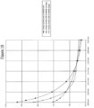
- FIG. 18 illustrates the influence of the air gap geometry on the attraction curve of the flat moving core.
- the attraction force is represented on the ordinate while the air gap is indicated on the abscissa.
- Three geometries are considered: a flat moving core with a flat air gap, a flat moving core with a conical air gap, and a flat moving core with a stepped air gap.
Landscapes
- Engineering & Computer Science (AREA)
- General Engineering & Computer Science (AREA)
- Mechanical Engineering (AREA)
- Magnetically Actuated Valves (AREA)
Description
- La présente invention est relative aux électrovannes miniatures couramment utilisées en pilotage de systèmes de distribution d'air comprimé à tiroir ou à clapet. Ces électrovannes miniatures agissent en multiplicateur et en contrôleur de puissance. En effet pour une faible puissance électrique d'entrée, souvent inférieure à 1W, la puissance pneumatique contrôlée de sortie est supérieure à 1kW.
- Le principe de construction des électrovannes miniatures repose sur des électroaimants dont l'élément mobile peut avoir deux types de construction.
- Le premier type de construction est caractérisé par un noyau de forme cylindrique, pénétrant profondément dans la partie centrale d'une bobine appartenant à l'électroaimant. Cette construction est communément appelée électrovanne à noyau plongeant.
- Le deuxième type de construction est caractérisé par un noyau de forme plate, ne pénétrant pas dans la partie centrale de la bobine. Cette construction est communément appelée électrovanne à noyau mobile plat.
- Dans le premier type de construction utilisant un noyau plongeant, l'état de l'art peut être illustré par le document
EP 1 536 169 . Cette construction se caractérise par une optimisation du flux magnétique, au détriment de la masse importante du noyau plongeant. Les forces de friction sont éliminées par l'utilisation de deux ressorts plats, servant notamment de guidage du noyau plongeant. - Dans le second type de construction utilisant un noyau mobile plat, l'état de l'art peut être illustré par le document
EP 0 549 490 . Cette construction se caractérise par une masse réduite du noyau mobile plat. Un ressort cylindrique sert de rappel. -
DE 10 2007 059 054 divulgue une électrovanne comportant une bague de maintien en matériau magnétique, insérée dans le corps de l'électrovanne. -
US 5 374 029 décrit une électrovanne comportant un noyau mobile à l'intérieur d'une bague en matériau magnétique, servant au rebouclage du flux magnétique. Une bague non magnétique s'interpose entre la bobine et cette bague magnétique. - La distance parcourue par le noyau mobile plat entre ses deux positions stables est appelée course.
- Notons que dans chacune de ces deux constructions, il existe deux entrefers principaux :
- l'entrefer situé perpendiculairement à l'axe principal de l'électrovanne. Cet entrefer est moteur. Il détermine directement la course du noyau et par conséquent le débit de la vanne. Il convient donc de maîtriser les dispersions au niveau de cet entrefer.
- l'entrefer situé radialement à l'axe principal de l'électrovanne. Cet entrefer n'est pas moteur. Il est cependant nécessaire pour permettre le mouvement du noyau dans son logement. Il convient également
de maîtriser cet entrefer afin de limiter son impact sur le bouclage du flux magnétique de l'électroaimant. - Dans les deux types de construction, la course du noyau dépend des dimensions d'un nombre important de pièces, mais aussi de la variabilité des points de fonctionnement des ressorts en fonction des caractéristiques des forces magnétiques de l'électroaimant. Il devient alors très difficile de produire des électrovannes miniatures avec une valeur de débit reproductible, et de garantir une faible puissance absorbée.
- La présente invention a pour but, notamment de proposer une électrovanne miniature de faible puissance absorbée, dont l'élément mobile peut être assimilé à un noyau mobile plat et dont la course et la force de rappel de ce noyau mobile plat puissent être mieux maîtrisés, afin que la valeur du débit soit reproductible.
- Selon l'invention, l'électrovanne comprend toutes les caractéristiques de la revendication 1.
- De manière avantageuse le ressort plat, associé à une bague de maintien, permet le réglage d'une force de pré-charge servant à étancher un orifice d'alimentation lorsque la vanne est en position repos, cela indépendamment du réglage de la course du noyau mobile plat.
- Le réglage de la course du noyau mobile plat peut être obtenu lors de la mise en place du sous-ensemble constitué de la bobine et du noyau fixe.
- L'orifice d'alimentation et le ou les orifice(s) d'utilisation peuvent être réalisés dans la partie basse du corps.
- La bague de maintien peut permettre le centrage du noyau fixe.
- L'orifice d'alimentation et le ou les orifice(s) d'utilisation peuvent être réalisés dans le fond, solidaire du corps.
- La carcasse de la bobine peut posséder plusieurs bossages.
- Le clapet peut posséder une forme polygonale.
- Le clapet peut être de forme cylindrique, un épaulement dans le noyau mobile plat faisant alors office de retenue.
- Le clapet peut posséder un épaulement.
- Un ressort conique peut être inséré entre l'épaulement du clapet et l'épaulement du noyau mobile plat.
- Une rondelle de centrage, en association avec le ressort plat de pré charge, peut permettre de centrer et guider le noyau mobile plat, tout en limitant les frottements de par la très faible épaisseur de la rondelle de centrage.
- Cette rondelle de centrage peut être remplacée par un second ressort plat, de faible raideur, pré-contraint par l'intermédiaire d'un épaulement dans le corps permettant d'assurer au noyau mobile plat, en association avec le ressort plat de rappel, un guidage sans aucun frottement, ni avec le corps, ni avec toute autre pièce interne.
- Le noyau mobile plat et le noyau fixe peuvent avoir une zone proche de l'entrefer dont la géométrie est de forme étagée.
- Le diamètre extérieur du noyau mobile plat peut être réduit de façon à limiter sa masse et en ce que ledit noyau mobile plat dispose d'un bourrelet en remplacement de la rondelle de guidage.
- La fonction de centrage du noyau mobile plat est alors obtenue, non pas par une rondelle de centrage, mais par le bourrelet réalisé directement sur le diamètre extérieur du noyau mobile plat.
- La forme externe de la section du corps peut être tronquée sur au moins deux faces opposées, formant ainsi des méplats.
- L'étanchéité du circuit fluidique de l'électrovanne par rapport à l'extérieur peut être obtenue, suivant la construction, par des joints toriques intégrés à l'électrovanne pilote, ou par des garnitures faisant partie intégrante de l'appareil ou du dispositif recevant l'électrovanne pilote.
- De manière avantageuse, tous les canaux fluidiques reliant l'électrovanne aux dispositifs externes, sont rectilignes et ne présentent donc pas de changement brutal de direction du fluide, d'où l'absence de pertes de charge localisées additionnelles, de la sorte le débit d'air est maximum pour une faible différence de pression.
- Le noyau mobile plat utilisé possède une forme particulière permettant de réaliser une caractéristique de force en fonction de la position adoptée, par l'influence des paramètres géométriques des entrefers. Cette forme permet de réduire l'entrefer magnétique sans changer la course utile et de modifier la caractéristique d'attraction de ce noyau mobile plat.
- L'optimisation de la force dynamique résultante est aussi obtenue en diminuant le plus possible le volume, donc la masse, du noyau mobile plat. La variabilité des points de fonctionnement du ressort plat est limitée par un réglage « in situ » de celui-ci, garantissant la valeur de la faible puissance absorbée.
- L'électrovanne miniature selon l'invention peut inclure également une structure monobloc du corps liant la partie électromagnétique à la partie fluidique, ici pneumatique. De la sorte, plusieurs fonctions principales de l'électrovanne sont réalisées en une seule pièce, permettant de limiter le nombre de composants et de réduire les dispersions d'assemblages. Cette optimisation peut donc avoir un impact non négligeable sur le coût du produit.
- Dans ce type de construction, le débit de l'orifice d'alimentation est directement contrôlé par la position du noyau mobile plat élément du système électromagnétique et pneumatique.
- D'autres caractéristiques et avantages de l'invention apparaîtront dans la description qui suit d'un mode de réalisation préféré avec référence aux dessins annexés mais qui n'a aucun caractère limitatif.
- Sur ces dessins :
-
Fig. 1 est une coupe longitudinale selon le plan B-B d'une électrovanne hors tension selon l'invention, -
Fig. 2 est une coupe longitudinale selon le plan A-A d'une électrovanne hors tension selon l'invention, -
Fig. 3 est une coupe longitudinale de l'électrovanne deFig. 2 sous tension, -
Fig. 4 est un détail illustrant la constitution de la bobine de l'électrovanne deFig. 1 , -
Fig. 5 est un détail illustrant le sous-ensemble bobine de l'électrovanne deFig. 1 , -
Fig. 6 est un détail illustrant l'assemblage du sous-ensemble bobine deFig. 5 , -
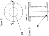
Fig. 6b est un détail illustrant des bossages intégrés à l'alésage principal de la carcasse définieFig. 4 . -
Fig. 6c est une coupe longitudinale selon le plan A-A deFig. 6b . -
Fig. 7 illustre un mode de réalisation alternatif de la forme du noyau mobile plat de l'électrovanne deFig. 1 , -
Fig. 7b illustre un mode de réalisation alternatif de la forme du noyau mobile plat de l'électrovanne deFig. 1 , -
Fig. 8 est une vue en perspective d'un clapet utilisé dans l'électrovanne deFig. 1 , -
Fig. 9 est une coupe longitudinale selon le plan A-A du clapet selonFig. 8 , inséré dans le noyau mobile plat de l'électrovanne deFig. 1 , -
Fig. 9b illustre un mode de réalisation alternatif de la forme du clapet illustréFig. 9 de l'électrovanne deFig. 1 , -
Fig. 9c illustre un autre mode de réalisation alternatif de la forme du clapet illustréFig. 9 de l'électrovanne deFig. 1 , -
Fig. 9d illustre la présence d'un ressort conique entre le clapet illustréFig. 9 et le noyau de l'électrovanne deFig. 1 , -
Fig. 10 est une coupe longitudinale selon le plan B-B du clapet monté dans le noyau mobile plat, selon -
Fig. 9 , inséré dans le noyau mobile plat de l'électrovanne deFig. 1 , -
Fig. 11 est une vue en perspective d'un premier mode de réalisation du corps de l'électrovanne deFig. 1 , -
Fig. 12 est une vue de dessus deFig. 11 , -
Fig. 13 est une vue en perspective d'un second mode de réalisation du corps de l'électrovanne deFig. 1 , -
Fig. 14 est une vue de dessus deFig. 13 , -
Fig. 15 et 16 sont des coupes similaires àFig. 2 illustrant des solutions alternatives d'étanchéité interne, -
Fig. 17 illustre un mode de réalisation alternatif de la forme du corps et du noyau mobile plat de l'électrovanne deFig. 1 , -
Fig. 18 est une courbe schématique représentant l'influence de la forme de l'entrefer magnétique sur la courbe d'attraction du noyau mobile plat, et -
Fig. 19 est un agrandissement deFig. 18 , dans la zone proche de l'entrefer de travail. - On peut voir
Figures 1 et 2 une électrovanne selon l'invention. - La partie magnétique de l'électrovanne permettant le bouclage du flux magnétique généré par la bobine 17, est composé d'un corps 4, d'un noyau fixe 3 et d'un noyau mobile plat 10 réalisés en matériau ferromagnétique.
- Le noyau mobile plat 10 se déplace suivant l'axe principal de l'électrovanne entre le noyau fixe 3 et la partie basse du corps 4.
- Le noyau mobile plat 10 qui se déplace suivant l'axe principal de l'électrovanne est soumis à une force de rappel élastique due au ressort plat 9. Cette force ajustable au montage est appelé pré-charge.
- La partie fluidique de l'électrovanne est composée du corps 4, du noyau fixe 3 et du noyau mobile plat 10 comportant un clapet à double face 12. La partie fluidique de l'électrovanne permet le contrôle des débits d'air à partir de l'orifice d'alimentation 18 vers le ou les orifice(s) d'utilisation 19 ou à partir du ou des orifice(s) d'utilisation 19 vers l'orifice d'échappement 20. Une construction alternative consiste à ne contrôler le passage du fluide qu'entre les orifices d'alimentation 18 et d'utilisation 19.
- L'étanchéité du circuit fluidique de l'électrovanne est obtenue d'une part par un joint oblong 7 emprisonné entre la carcasse de bobine 5 et une bague de maintien 8 assurant l'étanchéité interne, et d'autre part par les quatre joints toriques 2, 13, 15 et 26 assurant l'étanchéité externe.
- Cette fonction d'étanchéité externe peut également être réalisée par une ou plusieurs garnitures externes (non représentées), faisant partie intégrante de l'appareil ou du dispositif recevant l'électrovanne pilote, et remplaçant de ce fait un ou plusieurs joints toriques 2, 13, 15 et 26.
- Notons que la bague de maintien 8 est en matériau non magnétique de manière à ne pas influer sur les caractéristiques du champ magnétique.
- L'orifice d'alimentation 18 et le ou les orifice(s) d'utilisation 19 sont réalisés dans la partie basse du corps 4 appelée fond 4D. Contrairement au mode de réalisation généralement adopté dans l'art antérieur, le fond 4D est solidaire du corps 4. Ceci permet notamment de limiter les dispersions d'assemblage et par ce fait, de réaliser un réglage plus précis de la position de la bague 8 et de la course du noyau mobile plat 10.
- La
Figure 3 illustre l'électrovanne sous tension. Le noyau 10 muni du clapet 12 est alors en position haute, et en butée sur le noyau fixe 3. De la sorte l'orifice d'échappement 20 est obturé par l'action du clapet 12 sur le siège 22. - On peut voir
Figure 4 la constitution de la bobine 17. La bobine 17 est composée d'une carcasse de bobine 5, d'un bobinage 6 et de deux picots de connexion électrique 1. - La bobine 17, un joint oblong 7 et le noyau fixe 3 forment un sous-ensemble bobine 30 dont la constitution est plus particulièrement illustrée
Figure 5 . La bobine 17 est glissée le long de l'axe du noyau fixe 3 jusqu'à venir en butée sur celui-ci. Le joint oblong 7 est monté sur le noyau fixe 3 de façon à retenir la bobine 17 sur le noyau fixe 3. - La zone de connexion du sous-ensemble bobine 30 est plus particulièrement visible
Figure 6 . Les picots de connexion 1 ainsi que leurs supports 24 prévus dans la carcasse de bobine 5 passent à travers le noyau fixe 3 par l'intermédiaire de deux trous de passage 25 prévus à cet effet. Une résine 16 peut être injectée entre le noyau fixe 3 et la carcasse de bobine 5, afin de solidariser la bobine 17 et le noyau fixe 3. Cette opération s'effectue après insertion du sous-ensemble bobine 30 dans le corps 4. - Une alternative à l'utilisation de la résine 16 consiste à intégrer plusieurs bossages 33 dans l'alésage principal de la carcasse 5, tel que décrit en
Figures 6b et 6c , de façon à ce que le noyau fixe 3 soit monté sous contrainte dans la bobine 17. - La
Figure 7 illustre un mode de réalisation alternatif 10B de la forme du noyau mobile plat 10. Le but est ici de réaliser une caractéristique de force magnétique particulière entre le noyau mobile plat 10B et l'extrémité du noyau fixe 3B. Dans cet objectif on utilise des géométries particulières dans les zones proches de l'entrefer moteur. En comparaison avec un entrefer moteur plat classique et au voisinage de la position repos, le flux magnétique est en effet plus marqué pour une forme conique (Figure 1 ) ou étagée (Figure 7 ), permettant une caractéristique d'attraction identique pour une consommation d'énergie électrique réduite. En d'autres termes, le rendement le l'électroaimant au voisinage de l'entrefer de travail est plus élevé en utilisant l'une ou l'autre de ces deux géométries. - Il n'est pas exclu, de réaliser partiellement l'une ou l'autre de ces deux géométries d'entrefer, en combinaison avec une partie plate classique, dans le but d'obtenir un juste compromis entre faisabilité, fiabilité et performances du produit. Une combinaison d'entrefer conique et plat appliquée au noyau mobile plat 10C et au noyau fixe 3C est illustrée en
Figure 7b . - L'insertion du clapet 12, illustré en
Figure 8 , dans le noyau mobile plat 10 est plus particulièrement illustrée enFigures 9 et 10 . Ce clapet 12 de forme polygonale est inséré dans un perçage circulaire du noyau mobile plat 10. Cette forme particulière, polygonale, insérée dans un trou circulaire permet avantageusement de maintenir le clapet dans son logement, tout en prévenant toute déformation des surfaces portantes sur les sièges 21, 22 et en assurant le dégagement de toutes bavures relatives à la fermeture du moule du clapet. - De façon plus classique, le clapet 12B peut être de forme cylindrique, un épaulement 34 dans le noyau mobile plat 10D faisant alors office de retenue. Cette option est illustrée en
Figure 9b . - Une autre géométrie du clapet 12C, faisant apparaître un épaulement 35, peut également être réalisée, de façon à obtenir une plus grande flexibilité du clapet 12C à l'intérieur du noyau mobile plat 10E, permettant de favoriser le contact entre le noyau mobile plat 10E et le noyau fixe 3 lorsque la bobine 17 est sous tension. Cette option est illustrée en
Figure 9c . - Il est également possible d'insérer sous contrainte un ressort conique 36 entre l'épaulement 35 du clapet 12C et l'épaulement 34 du noyau mobile plat 10D. Cette alternative est illustrée en
Figure 9d . - La conception de l'électrovanne permet le montage de tous les constituants internes par l'arrière du corps 4, par l'intermédiaire d'une ouverture 23 notamment apte à l'insertion du noyau mobile plat 10, du noyau fixe 3 et de la bobine 17. La conception de l'électrovanne permet également l'indépendance des réglages de la course et de la pré-charge. Le montage des différents éléments de l'électrovanne est explicité ci-après.
- La rondelle de centrage 11 et l'ensemble noyau mobile plat 10, 12 sont placés dans la partie basse du corps 4. Le ressort plat 9 est alors ensuite inséré et vient au contact de l'ensemble noyau mobile plat 10, 12.
- La bague de maintien 8 est insérée dans le corps 4 jusqu'au contact avec le ressort plat 9. Le ressort plat 9 exerce la pré-charge sur l'ensemble noyau mobile plat 10, 12 et l'ensemble noyau mobile plat 10, 12 vient en contact de l'orifice d'alimentation 18. L'effort de pré-charge est alors vérifié par un moyen adéquat.
- Lorsque la position de la bague de maintien 8 est telle que l'effort de pré-charge atteint une valeur correcte prédéfinie, la bague de maintien 8 est sertie sur le corps 4.
- Le sous-ensemble bobine 30 est ensuite inséré dans le corps 4 jusqu'à une position telle que la course atteint une valeur satisfaisante. Lors de cette opération la valeur de la course est vérifiée par alternance de prises de positions entre la position repos, bobine non alimentée, et la position actionnée, bobine alimentée, de telle sorte que la course soit définie avec une précision de l'ordre de quelques dizaines de micromètres.
- La bague de maintien 8 a également pour fonction de centrer la partie basse du noyau fixe 3, par rapport au noyau mobile plat 10, lors de l'insertion du sous-ensemble bobine 30 dans le corps 4.
- Le corps 4 et le sous-ensemble bobine 30 sont alors sertis au travers du noyau fixe 3 en partie haute de l'électrovanne.
- En position repos, bobine non alimentée, l'orifice d'alimentation 18 est obturée par le clapet 12, grâce à la pré-charge exercée par le ressort plat 9 sur le noyau mobile plat 10 permettant de maintenir un effort sur le siège 21 de l'orifice d'alimentation 18, nécessaire pour assurer l'isolation de cette dernière par rapport aux autres orifices 19 et 20. Le ou les orifice(s) d'utilisation 19 et l'orifice d'échappement 20 sont alors en liaison, par l'intermédiaire d'un ou plusieurs orifice(s) de liaison 14 du noyau mobile plat 10. Notons que le ressort plat 9 ainsi que la rondelle de centrage 11 sont suffisamment ajourées pour ne pas perturber le passage du fluide.
- En position actionnée, bobine alimentée, le noyau mobile plat 10 est attiré magnétiquement par le noyau fixe 3 jusqu'au contact entre ces deux pièces, appelé collage. L'orifice d'échappement 20 est alors obturé par le clapet 12. La pression exercée sur ce dernier par l'air comprimé provenant de l'orifice d'alimentation 18 permet de maintenir un effort sur le siège 22 de l'orifice d'échappement 20, nécessaire pour assurer l'isolation de cette dernière par rapport aux autres orifices 18 et 19. L'orifice d'alimentation 18 et le ou les orifice(s) d'utilisation 19 sont alors en liaison.
- Les
Figures 11 à 14 illustrent des exemples de réalisation du corps 4, dont les faces latérales peuvent être tronquées sur deux faces opposées (Figures 13 et 14 ) ou sur quatre faces (Figures 11 et 12 ). Les faces latérales deviennent alors des méplats. La réduction localisée de l'épaisseur du corps 4 ainsi provoquée permet l'optimisation des opérations de sertissage du sous-ensemble bobine 30 et du corps 4 ainsi que de la bague de maintien 8 avec ce même corps 4, tout en maintenant une section nécessaire et suffisante de matériau magnétique dans les zones épaisses afin d'assurer la circulation du flux magnétique sans saturation. Ces modes de réalisation permettent également de limiter l'encombrement latéral du produit dans au moins une direction. - Les
Figures 15 et 16 illustrent des modes de réalisation alternatifs relatifs à l'utilisation du joint 7 de forme oblongue, assurant l'étanchéité interne du produit. Ce joint oblong 7 est alors remplacé par deux joints toriques 31 et 32, dont les logements respectifs 41 et 42 sont réalisés soit dans la carcasse de bobine 5 (Figure 15 ), soit dans la bague de maintien 8 (Figure 16 ). - La
Figure 17 illustre un mode de réalisation alternatif 4C du corps 4 et 10C du noyau mobile plat 10. Dans ce mode de réalisation, le diamètre extérieur du noyau mobile plat 10C est réduit, afin de limiter davantage l'impact de la masse de ce noyau mobile plat 10C sur les performances du produit. La rondelle de guidage 11 est alors supprimée et la fonction de guidage du noyau mobile plat 10C est alors remplacée par un bourrelet 28, réalisé sur le noyau mobile plat 10C. Ce bourrelet 28 est dimensionné de façon à limiter au maximum les frottements entre le noyau mobile plat 10C et le corps 4C. Dans ce mode de réalisation, le ou les orifice(s) de liaison 14, 19 sont réalisés dans le corps 4C. - La
Figure 18 illustre l'influence de la géométrie de l'entrefer sur la courbe d'attraction du noyau mobile plat. L'effort d'attraction est représenté en ordonnée tandis que l'entrefer est indiqué en abscisse. Trois géométries sont considérées : un noyau mobile plat à entrefer plat, un noyau mobile plat à entrefer conique, un noyau mobile plat à entrefer étagé. - Dans la solution utilisant un noyau mobile plat à entrefer plat, en dehors du cas très particulier d'une valeur d'entrefer extrêmement faible, il n'y pas de saturation avant le collage. La courbe représentative de l'effort d'attraction a la forme d'une branche d'hyperbole. La force d'attraction est très importante au collage, mais faible à l'entrefer de travail (position repos).
- Dans la solution utilisant un noyau mobile plat à entrefer conique, le niveau de flux magnétique de la partie conique est presque indépendant de l'écart de l'entrefer. La conséquence de cet effet est que la force d'attraction est pratiquement constante tout au long de la course et que la variation globale de la force d'attraction entre le collage et l'entrefer maximum est diminuée de moitié par rapport à la solution utilisant un noyau mobile plat à entrefer plat. En contrepartie, si l'on considère un entrefer de travail de 0.25 mm, la force d'attraction du noyau est supérieure d'environ 18% à celle d'un noyau mobile plat à entrefer plat.
- Dans la solution utilisant un noyau mobile plat à entrefer étagé, on obtient également une force d'attraction pratiquement constante pour environ 50% de la course. Mais la répartition différente du flux magnétique des échelons formant l'étagement du noyau, conduit, pour les entrefers très faibles, à une augmentation de la force de collage. La force d'attraction lors du collage reste néanmoins inférieure au cas d'une solution utilisant un noyau mobile plat à entrefer plat. Cependant, l'intérêt majeur de cette solution est de présenter un gain d'effort d'environ 33% par rapport à la solution d'un noyau mobile plat à entrefer plat, en considérant également un entrefer de travail de 0.25 mm.
Claims (14)
- Electrovanne comprenant un électroaimant (17, 4, 3, 10), composé d' un noyau mobile plat (10), d'un noyau fixe (3) et d'une bobine (17), comportant un corps (4), appartenant également à l'électroaimant et comprenant une ouverture (23), située à l'arrière du corps (4) à l'opposé de l'orifice d'alimentation (18), apte à l'insertion du noyau mobile plat (10), du noyau fixe (3) et de la bobine (17),
l'électrovanne comportant également une bague de maintien (8) réalisée en matériau non magnétique et un ressort plat (9), caractérisée en ce que le corps (4) est solidaire de la bague de maintien (8), la bague de maintien (8) étant sertie sur le corps (4) , et en ce que le ressort plat (9) est comprimé entre la bague de maintien (8) et le noyau mobile plat (10). - Electrovanne suivant la revendication 1, caractérisée en ce que le ressort plat (9), associé à la bague de maintien (8), permet le réglage d'une force de pré-charge servant à étancher un orifice d'alimentation (18) lorsque la vanne est en position repos, cela indépendamment du réglage de la course du noyau mobile plat (10).
- Electrovanne suivant la revendication 1 ou 2, caractérisée en ce que le réglage de la course du noyau mobile plat (10) est obtenu lors de la mise en place de la bobine (17) et du noyau fixe (3).
- Electrovanne selon l'une quelconque des revendications précédentes, caractérisée en ce que la bague de maintien (8) permet le centrage du noyau fixe (3).
- Electrovanne selon l'une quelconque des revendications précédentes, caractérisée en ce que l'orifice d'alimentation (18) et le ou les orifice(s) d'utilisation (19) sont réalisés dans le fond (4D), solidaire du corps (4).
- Electrovanne selon l'une quelconque des revendications précédentes, caractérisée en ce que la carcasse (5) de la bobine (17) possède plusieurs bossages (33).
- Electrovanne selon l'une quelconque des revendications précédentes, caractérisée en ce que le clapet (12) de l'électrovanne possède une forme polygonale.
- Electrovanne selon l'une quelconque des revendications précédentes, caractérisée en ce que le clapet (12B) de l'électrovanne est de forme cylindrique, un épaulement (34) dans le noyau mobile plat (10D) faisant alors office de retenue.
- Electrovanne selon l'une quelconque des revendications précédentes, caractérisée en ce que le clapet (12C) de l'électrovanne possède un épaulement (35).
- Electrovanne selon les revendications 8 et 9, caractérisée en ce qu'un ressort conique (36) est inséré entre l'épaulement (35) du clapet (12C) et l'épaulement (34) du noyau mobile plat (10D).
- Electrovanne selon l'une quelconque des revendications précédentes, caractérisée en ce que le noyau mobile plat (10) et le noyau fixe (3) comportent, au voisinage de l'entrefer, une zone de forme étagée.
- Electrovanne selon l'une quelconque des revendications précédentes, caractérisée en ce que le diamètre extérieur du noyau mobile plat (10) est réduit de façon à limiter sa masse et en ce que ledit noyau mobile plat (10) dispose d'un bourrelet (28) en remplacement d'une rondelle de guidage (11) de l'électrovanne.
- Electrovanne selon l'une quelconque des revendications précédentes, caractérisée en ce que la forme externe de la section du corps (4) est tronquée sur au moins deux faces opposées, formant ainsi des méplats.
- Electrovanne selon l'une quelconque des revendications précédentes, caractérisée en ce que tous les canaux fluidiques (18), (19), (20) reliant l'électrovanne aux dispositifs externes, sont rectilignes.
Applications Claiming Priority (2)
| Application Number | Priority Date | Filing Date | Title |
|---|---|---|---|
| FR1000398A FR2955908B1 (fr) | 2010-02-02 | 2010-02-02 | Electrovanne pilote |
| PCT/IB2011/050415 WO2011095928A1 (fr) | 2010-02-02 | 2011-01-31 | Electrovanne pilote |
Publications (3)
| Publication Number | Publication Date |
|---|---|
| EP2531756A1 EP2531756A1 (fr) | 2012-12-12 |
| EP2531756B1 EP2531756B1 (fr) | 2019-08-14 |
| EP2531756B2 true EP2531756B2 (fr) | 2025-04-23 |
Family
ID=42989282
Family Applications (1)
| Application Number | Title | Priority Date | Filing Date |
|---|---|---|---|
| EP11705269.6A Active EP2531756B2 (fr) | 2010-02-02 | 2011-01-31 | Electrovanne pilote |
Country Status (7)
| Country | Link |
|---|---|
| US (1) | US9273791B2 (fr) |
| EP (1) | EP2531756B2 (fr) |
| JP (1) | JP5979790B2 (fr) |
| CN (1) | CN102869910B (fr) |
| ES (1) | ES2751152T5 (fr) |
| FR (1) | FR2955908B1 (fr) |
| WO (1) | WO2011095928A1 (fr) |
Families Citing this family (33)
| Publication number | Priority date | Publication date | Assignee | Title |
|---|---|---|---|---|
| DE102011077069A1 (de) * | 2011-06-07 | 2012-12-13 | Robert Bosch Gmbh | Elektromagnetisch betätigbares Ventil |
| US9851103B2 (en) | 2011-12-15 | 2017-12-26 | Honeywell International Inc. | Gas valve with overpressure diagnostics |
| US9846440B2 (en) | 2011-12-15 | 2017-12-19 | Honeywell International Inc. | Valve controller configured to estimate fuel comsumption |
| US8905063B2 (en) | 2011-12-15 | 2014-12-09 | Honeywell International Inc. | Gas valve with fuel rate monitor |
| US9557059B2 (en) | 2011-12-15 | 2017-01-31 | Honeywell International Inc | Gas valve with communication link |
| US8947242B2 (en) | 2011-12-15 | 2015-02-03 | Honeywell International Inc. | Gas valve with valve leakage test |
| US8839815B2 (en) | 2011-12-15 | 2014-09-23 | Honeywell International Inc. | Gas valve with electronic cycle counter |
| US9995486B2 (en) | 2011-12-15 | 2018-06-12 | Honeywell International Inc. | Gas valve with high/low gas pressure detection |
| US9074770B2 (en) | 2011-12-15 | 2015-07-07 | Honeywell International Inc. | Gas valve with electronic valve proving system |
| US8899264B2 (en) | 2011-12-15 | 2014-12-02 | Honeywell International Inc. | Gas valve with electronic proof of closure system |
| US9835265B2 (en) | 2011-12-15 | 2017-12-05 | Honeywell International Inc. | Valve with actuator diagnostics |
| FR2993035B1 (fr) | 2012-07-05 | 2015-02-20 | Asco Joucomatic Sa | Electrovanne du type a noyau plat et ressort plat. |
| US9234661B2 (en) | 2012-09-15 | 2016-01-12 | Honeywell International Inc. | Burner control system |
| US10422531B2 (en) | 2012-09-15 | 2019-09-24 | Honeywell International Inc. | System and approach for controlling a combustion chamber |
| EP2868970B1 (fr) | 2013-10-29 | 2020-04-22 | Honeywell Technologies Sarl | Dispositif de régulation |
| US10024439B2 (en) | 2013-12-16 | 2018-07-17 | Honeywell International Inc. | Valve over-travel mechanism |
| JP2015138937A (ja) * | 2014-01-24 | 2015-07-30 | 新電元メカトロニクス株式会社 | ソレノイド |
| CN104089072A (zh) * | 2014-06-17 | 2014-10-08 | 贵州新安航空机械有限责任公司 | 一种增强电磁力的电磁阀铁芯结构 |
| JP6200869B2 (ja) * | 2014-08-20 | 2017-09-20 | 株式会社コガネイ | 電磁弁 |
| US9841122B2 (en) | 2014-09-09 | 2017-12-12 | Honeywell International Inc. | Gas valve with electronic valve proving system |
| US9645584B2 (en) | 2014-09-17 | 2017-05-09 | Honeywell International Inc. | Gas valve with electronic health monitoring |
| US10503181B2 (en) | 2016-01-13 | 2019-12-10 | Honeywell International Inc. | Pressure regulator |
| US10564062B2 (en) | 2016-10-19 | 2020-02-18 | Honeywell International Inc. | Human-machine interface for gas valve |
| US20180157279A1 (en) * | 2016-12-02 | 2018-06-07 | RAM Manufacturing Company, Inc. | Electronic Fluid Metering Valve |
| US10578220B2 (en) | 2017-02-27 | 2020-03-03 | Bimba Manufacturing Company | Proportionally controlled pinch valves, systems and methods |
| US10422438B2 (en) * | 2017-04-19 | 2019-09-24 | Fisher Controls International Llc | Electro-pneumatic converters and related methods |
| US11073281B2 (en) | 2017-12-29 | 2021-07-27 | Honeywell International Inc. | Closed-loop programming and control of a combustion appliance |
| US10697815B2 (en) | 2018-06-09 | 2020-06-30 | Honeywell International Inc. | System and methods for mitigating condensation in a sensor module |
| AT16929U1 (de) * | 2019-05-28 | 2020-12-15 | Zieger Dipl Ing Andreas | Kombinationsventil |
| DE102020005978B4 (de) | 2020-09-30 | 2022-09-29 | Staiger Lebensräume Gmbh & Co. Kg | Ventil |
| KR102854827B1 (ko) * | 2020-11-10 | 2025-09-04 | 현대자동차주식회사 | 솔레노이드 밸브 |
| DE102021212172A1 (de) | 2021-10-28 | 2023-05-04 | Robert Bosch Gesellschaft mit beschränkter Haftung | Magnetventil |
| CN118361576A (zh) * | 2024-04-29 | 2024-07-19 | 采埃孚商用车系统(青岛)有限公司 | 电磁阀及其装配方法 |
Family Cites Families (34)
| Publication number | Priority date | Publication date | Assignee | Title |
|---|---|---|---|---|
| US3508568A (en) * | 1967-11-29 | 1970-04-28 | Marotta Valve Corp | Pressure responsive valves |
| US3921670A (en) * | 1974-07-01 | 1975-11-25 | Clippard Instr Lab Inc | Magnetically operated valve with spider armature |
| JPS5312251B2 (fr) * | 1974-12-17 | 1978-04-27 | ||
| US4196751A (en) * | 1976-01-15 | 1980-04-08 | Johnson Controls, Inc. | Electric to fluid signal valve unit |
| US4210890A (en) * | 1978-09-27 | 1980-07-01 | Warner Electric Brake & Clutch Company | Field assembly for an electromagnet |
| JPS58214084A (ja) * | 1982-06-08 | 1983-12-13 | Nippon Denso Co Ltd | 電磁弁 |
| JPH0272880U (fr) * | 1988-11-21 | 1990-06-04 | ||
| JP3063983B2 (ja) * | 1989-05-22 | 2000-07-12 | 株式会社エステック | 流量制御弁 |
| JPH039180A (ja) * | 1989-06-02 | 1991-01-17 | Mitsubishi Electric Corp | 弁装置 |
| JPH0536175U (ja) * | 1990-12-17 | 1993-05-18 | 株式会社コガネイ | 電磁弁 |
| FR2685429B1 (fr) | 1991-12-23 | 1995-02-10 | Eaton Sa Monaco | Electrovanne a noyau mobile plat. |
| US5306076A (en) * | 1992-05-20 | 1994-04-26 | G. W. Lisk Company, Inc. | Proportional control valve with pressure compensation |
| US5374029A (en) * | 1992-06-26 | 1994-12-20 | Wright Components, Inc. | Solenoid flow control valve and frictionless plunger assembly |
| JP3810488B2 (ja) * | 1996-08-13 | 2006-08-16 | 株式会社ニッキ | 燃料噴射弁 |
| JPH10318413A (ja) | 1997-05-14 | 1998-12-04 | Citizen Electron Co Ltd | 流量コントロール弁 |
| US6163239A (en) | 1997-08-25 | 2000-12-19 | Mitsubishi Denki Kabushiki Kaisha | Duty driven solenoid valve |
| JP4077915B2 (ja) * | 1997-12-12 | 2008-04-23 | 株式会社不二工機 | 電磁弁及び該電磁弁を備えた多段式流量制御弁 |
| DE19820341C2 (de) * | 1998-05-07 | 2000-04-06 | Daimler Chrysler Ag | Betätigungsvorrichtung für eine Hochdruck-Einspritzdüse für flüssige Einspritzmedien |
| DE19827069B4 (de) | 1998-06-18 | 2008-09-18 | Steuerungstechnik Staiger Gmbh & Co. Produktions-Vertriebs-Kg | Ventil |
| DE19827874B4 (de) | 1998-06-23 | 2006-12-07 | Steuerungstechnik Staiger Gmbh & Co. Produktions-Vertriebs-Kg | Ventil |
| US6220569B1 (en) * | 2000-01-07 | 2001-04-24 | Clippard Instrument Laboratory, Inc. | Electrically controlled proportional valve |
| DE60017427T2 (de) | 2000-12-19 | 2006-01-26 | Fluid Automation Systems S.A. | Elektromagnetventil |
| EP1350999B1 (fr) | 2002-03-28 | 2006-08-02 | Fluid Automation Systems S.A. | Vanne électromagnétique |
| DE10215592C1 (de) | 2002-04-10 | 2003-05-15 | Staiger Steuerungstech | Ventil |
| DE20205488U1 (de) * | 2002-04-10 | 2003-08-28 | Steuerungstechnik Staiger GmbH & Co. Produktions-Vertriebs-KG, 74391 Erligheim | Ventil |
| EP1536169B1 (fr) | 2003-11-29 | 2008-11-05 | Asco Joucomatic GmbH | Soupape électromagnétique |
| JP4296081B2 (ja) * | 2003-12-09 | 2009-07-15 | シーケーディ株式会社 | 電磁弁 |
| JP4686340B2 (ja) * | 2005-11-15 | 2011-05-25 | シーケーディ株式会社 | プロセスガス制御弁の付着物除去方法及びプロセスガス制御弁の制御装置 |
| EP2064472B1 (fr) | 2006-09-07 | 2016-08-31 | Fluid Automation Systems S.A. | Soupape bistable |
| DE102007059054A1 (de) * | 2007-12-06 | 2009-06-10 | Eks Elektromagnetik Gmbh | Elektromagnetische Stellvorrichtung |
| DE102008017764B4 (de) | 2008-04-08 | 2014-10-30 | Staiger Gmbh & Co. Kg | Ventil |
| DE202008017153U1 (de) | 2008-08-12 | 2009-04-02 | Staiger Gmbh & Co. Kg | Ventil |
| CN201344272Y (zh) * | 2009-03-15 | 2009-11-11 | 蒋可贞 | 活塞式先导电磁阀 |
| US8128060B2 (en) * | 2009-03-25 | 2012-03-06 | Valve Tech, Inc. | Non-sliding solenoid valve |
-
2010
- 2010-02-02 FR FR1000398A patent/FR2955908B1/fr active Active
-
2011
- 2011-01-31 EP EP11705269.6A patent/EP2531756B2/fr active Active
- 2011-01-31 ES ES11705269T patent/ES2751152T5/es active Active
- 2011-01-31 US US13/576,238 patent/US9273791B2/en active Active
- 2011-01-31 CN CN201180008277.3A patent/CN102869910B/zh active Active
- 2011-01-31 WO PCT/IB2011/050415 patent/WO2011095928A1/fr not_active Ceased
- 2011-01-31 JP JP2012551716A patent/JP5979790B2/ja not_active Expired - Fee Related
Also Published As
| Publication number | Publication date |
|---|---|
| ES2751152T5 (en) | 2025-09-01 |
| US20120298896A1 (en) | 2012-11-29 |
| CN102869910A (zh) | 2013-01-09 |
| FR2955908B1 (fr) | 2012-05-04 |
| US9273791B2 (en) | 2016-03-01 |
| EP2531756A1 (fr) | 2012-12-12 |
| JP2013519051A (ja) | 2013-05-23 |
| FR2955908A1 (fr) | 2011-08-05 |
| JP5979790B2 (ja) | 2016-08-31 |
| WO2011095928A1 (fr) | 2011-08-11 |
| CN102869910B (zh) | 2014-09-24 |
| ES2751152T3 (es) | 2020-03-30 |
| EP2531756B1 (fr) | 2019-08-14 |
Similar Documents
| Publication | Publication Date | Title |
|---|---|---|
| EP2531756B2 (fr) | Electrovanne pilote | |
| US8443839B2 (en) | Fluid-biased hydraulic control valve with armature piston | |
| EP3524866B1 (fr) | Vanne fluidique | |
| EP2333298B1 (fr) | Soupape électromagnétique de commande d'un injecteur ou de régulation de pression d'un accumulateur de carburant à haute pression. | |
| FR2935771A1 (fr) | Dispositif de commande de l'alimentation d'un systeme avec un fluide | |
| FR2872242A1 (fr) | Electrovanne comportant un induit dont la face frontale n'est pas lisse | |
| FR2956715A1 (fr) | Soupape electromagnetique pour commander un fluide | |
| FR2962779A1 (fr) | Electrovanne equipee d'un ressort forme | |
| FR2954447A1 (fr) | Electrovanne et installation d'assistance de conduite equipee d'au moins une telle electrovanne | |
| FR2689599A1 (fr) | Distributeur à commande électromagnétique, à trois voies et trois positions. | |
| FR2998025A1 (fr) | Vanne | |
| EP3209877B1 (fr) | Injecteur de carburant | |
| FR2956716A1 (fr) | Soupape electromagnetique pour commander un fluide | |
| FR2889621A1 (fr) | Actionneur electromagnetique comportant un tube magnetique et destine a actionner une vanne hydraulique ou pneumatique | |
| EP1815174B1 (fr) | Vanne incorporant un moyen d'equilibrage des pressions de part et d'autre du clapet. | |
| EP3098403B1 (fr) | Dispositif de commande d'une alimentation en fluide sous pression | |
| FR3029591B1 (fr) | Soupape electromagnetique de regulation et/ou de limitation de pression | |
| EP0006770B1 (fr) | Electrovanne, notamment pour carburateur | |
| CN100467855C (zh) | 燃油喷射阀 | |
| EP1132581B1 (fr) | Soupape à commande électromagnétique, à ressort pneumatique et articulation par genouillère | |
| US20140231681A1 (en) | Electromagnetically-actuated piloted valve | |
| FR3007802B1 (fr) | Soupape de commande de systeme d'injection a rampe commune | |
| FR2977293A1 (fr) | Electrovanne | |
| EP2640959A1 (fr) | Regulateur de pression et dispositif d'alimentation en carburant comportant un tel regulateur | |
| FR2967809A1 (fr) | Installation d'actionnement electromagnetique comportant un boitier, un induit mobile et une bobine |
Legal Events
| Date | Code | Title | Description |
|---|---|---|---|
| PUAI | Public reference made under article 153(3) epc to a published international application that has entered the european phase |
Free format text: ORIGINAL CODE: 0009012 |
|
| 17P | Request for examination filed |
Effective date: 20120731 |
|
| AK | Designated contracting states |
Kind code of ref document: A1 Designated state(s): AL AT BE BG CH CY CZ DE DK EE ES FI FR GB GR HR HU IE IS IT LI LT LU LV MC MK MT NL NO PL PT RO RS SE SI SK SM TR |
|
| DAX | Request for extension of the european patent (deleted) | ||
| 17Q | First examination report despatched |
Effective date: 20140408 |
|
| RAP1 | Party data changed (applicant data changed or rights of an application transferred) |
Owner name: ASCO SAS |
|
| GRAP | Despatch of communication of intention to grant a patent |
Free format text: ORIGINAL CODE: EPIDOSNIGR1 |
|
| STAA | Information on the status of an ep patent application or granted ep patent |
Free format text: STATUS: GRANT OF PATENT IS INTENDED |
|
| INTG | Intention to grant announced |
Effective date: 20190121 |
|
| GRAJ | Information related to disapproval of communication of intention to grant by the applicant or resumption of examination proceedings by the epo deleted |
Free format text: ORIGINAL CODE: EPIDOSDIGR1 |
|
| STAA | Information on the status of an ep patent application or granted ep patent |
Free format text: STATUS: EXAMINATION IS IN PROGRESS |
|
| GRAP | Despatch of communication of intention to grant a patent |
Free format text: ORIGINAL CODE: EPIDOSNIGR1 |
|
| STAA | Information on the status of an ep patent application or granted ep patent |
Free format text: STATUS: GRANT OF PATENT IS INTENDED |
|
| INTC | Intention to grant announced (deleted) | ||
| INTG | Intention to grant announced |
Effective date: 20190411 |
|
| GRAS | Grant fee paid |
Free format text: ORIGINAL CODE: EPIDOSNIGR3 |
|
| GRAA | (expected) grant |
Free format text: ORIGINAL CODE: 0009210 |
|
| STAA | Information on the status of an ep patent application or granted ep patent |
Free format text: STATUS: THE PATENT HAS BEEN GRANTED |
|
| AK | Designated contracting states |
Kind code of ref document: B1 Designated state(s): AL AT BE BG CH CY CZ DE DK EE ES FI FR GB GR HR HU IE IS IT LI LT LU LV MC MK MT NL NO PL PT RO RS SE SI SK SM TR |
|
| REG | Reference to a national code |
Ref country code: GB Ref legal event code: FG4D Free format text: NOT ENGLISH |
|
| REG | Reference to a national code |
Ref country code: CH Ref legal event code: EP Ref country code: AT Ref legal event code: REF Ref document number: 1167430 Country of ref document: AT Kind code of ref document: T Effective date: 20190815 |
|
| REG | Reference to a national code |
Ref country code: IE Ref legal event code: FG4D Free format text: LANGUAGE OF EP DOCUMENT: FRENCH |
|
| REG | Reference to a national code |
Ref country code: DE Ref legal event code: R096 Ref document number: 602011061238 Country of ref document: DE |
|
| REG | Reference to a national code |
Ref country code: NL Ref legal event code: MP Effective date: 20190814 |
|
| REG | Reference to a national code |
Ref country code: LT Ref legal event code: MG4D |
|
| PG25 | Lapsed in a contracting state [announced via postgrant information from national office to epo] |
Ref country code: NL Free format text: LAPSE BECAUSE OF FAILURE TO SUBMIT A TRANSLATION OF THE DESCRIPTION OR TO PAY THE FEE WITHIN THE PRESCRIBED TIME-LIMIT Effective date: 20190814 Ref country code: LT Free format text: LAPSE BECAUSE OF FAILURE TO SUBMIT A TRANSLATION OF THE DESCRIPTION OR TO PAY THE FEE WITHIN THE PRESCRIBED TIME-LIMIT Effective date: 20190814 Ref country code: FI Free format text: LAPSE BECAUSE OF FAILURE TO SUBMIT A TRANSLATION OF THE DESCRIPTION OR TO PAY THE FEE WITHIN THE PRESCRIBED TIME-LIMIT Effective date: 20190814 Ref country code: SE Free format text: LAPSE BECAUSE OF FAILURE TO SUBMIT A TRANSLATION OF THE DESCRIPTION OR TO PAY THE FEE WITHIN THE PRESCRIBED TIME-LIMIT Effective date: 20190814 Ref country code: PT Free format text: LAPSE BECAUSE OF FAILURE TO SUBMIT A TRANSLATION OF THE DESCRIPTION OR TO PAY THE FEE WITHIN THE PRESCRIBED TIME-LIMIT Effective date: 20191216 Ref country code: HR Free format text: LAPSE BECAUSE OF FAILURE TO SUBMIT A TRANSLATION OF THE DESCRIPTION OR TO PAY THE FEE WITHIN THE PRESCRIBED TIME-LIMIT Effective date: 20190814 Ref country code: BG Free format text: LAPSE BECAUSE OF FAILURE TO SUBMIT A TRANSLATION OF THE DESCRIPTION OR TO PAY THE FEE WITHIN THE PRESCRIBED TIME-LIMIT Effective date: 20191114 Ref country code: NO Free format text: LAPSE BECAUSE OF FAILURE TO SUBMIT A TRANSLATION OF THE DESCRIPTION OR TO PAY THE FEE WITHIN THE PRESCRIBED TIME-LIMIT Effective date: 20191114 |
|
| REG | Reference to a national code |
Ref country code: AT Ref legal event code: MK05 Ref document number: 1167430 Country of ref document: AT Kind code of ref document: T Effective date: 20190814 |
|
| PG25 | Lapsed in a contracting state [announced via postgrant information from national office to epo] |
Ref country code: IS Free format text: LAPSE BECAUSE OF FAILURE TO SUBMIT A TRANSLATION OF THE DESCRIPTION OR TO PAY THE FEE WITHIN THE PRESCRIBED TIME-LIMIT Effective date: 20191214 Ref country code: LV Free format text: LAPSE BECAUSE OF FAILURE TO SUBMIT A TRANSLATION OF THE DESCRIPTION OR TO PAY THE FEE WITHIN THE PRESCRIBED TIME-LIMIT Effective date: 20190814 Ref country code: AL Free format text: LAPSE BECAUSE OF FAILURE TO SUBMIT A TRANSLATION OF THE DESCRIPTION OR TO PAY THE FEE WITHIN THE PRESCRIBED TIME-LIMIT Effective date: 20190814 Ref country code: GR Free format text: LAPSE BECAUSE OF FAILURE TO SUBMIT A TRANSLATION OF THE DESCRIPTION OR TO PAY THE FEE WITHIN THE PRESCRIBED TIME-LIMIT Effective date: 20191115 Ref country code: RS Free format text: LAPSE BECAUSE OF FAILURE TO SUBMIT A TRANSLATION OF THE DESCRIPTION OR TO PAY THE FEE WITHIN THE PRESCRIBED TIME-LIMIT Effective date: 20190814 |
|
| REG | Reference to a national code |
Ref country code: ES Ref legal event code: FG2A Ref document number: 2751152 Country of ref document: ES Kind code of ref document: T3 Effective date: 20200330 |
|
| PG25 | Lapsed in a contracting state [announced via postgrant information from national office to epo] |
Ref country code: TR Free format text: LAPSE BECAUSE OF FAILURE TO SUBMIT A TRANSLATION OF THE DESCRIPTION OR TO PAY THE FEE WITHIN THE PRESCRIBED TIME-LIMIT Effective date: 20190814 |
|
| PG25 | Lapsed in a contracting state [announced via postgrant information from national office to epo] |
Ref country code: DK Free format text: LAPSE BECAUSE OF FAILURE TO SUBMIT A TRANSLATION OF THE DESCRIPTION OR TO PAY THE FEE WITHIN THE PRESCRIBED TIME-LIMIT Effective date: 20190814 Ref country code: AT Free format text: LAPSE BECAUSE OF FAILURE TO SUBMIT A TRANSLATION OF THE DESCRIPTION OR TO PAY THE FEE WITHIN THE PRESCRIBED TIME-LIMIT Effective date: 20190814 Ref country code: EE Free format text: LAPSE BECAUSE OF FAILURE TO SUBMIT A TRANSLATION OF THE DESCRIPTION OR TO PAY THE FEE WITHIN THE PRESCRIBED TIME-LIMIT Effective date: 20190814 Ref country code: PL Free format text: LAPSE BECAUSE OF FAILURE TO SUBMIT A TRANSLATION OF THE DESCRIPTION OR TO PAY THE FEE WITHIN THE PRESCRIBED TIME-LIMIT Effective date: 20190814 Ref country code: RO Free format text: LAPSE BECAUSE OF FAILURE TO SUBMIT A TRANSLATION OF THE DESCRIPTION OR TO PAY THE FEE WITHIN THE PRESCRIBED TIME-LIMIT Effective date: 20190814 |
|
| REG | Reference to a national code |
Ref country code: DE Ref legal event code: R026 Ref document number: 602011061238 Country of ref document: DE |
|
| PLBI | Opposition filed |
Free format text: ORIGINAL CODE: 0009260 |
|
| PG25 | Lapsed in a contracting state [announced via postgrant information from national office to epo] |
Ref country code: SM Free format text: LAPSE BECAUSE OF FAILURE TO SUBMIT A TRANSLATION OF THE DESCRIPTION OR TO PAY THE FEE WITHIN THE PRESCRIBED TIME-LIMIT Effective date: 20190814 Ref country code: SK Free format text: LAPSE BECAUSE OF FAILURE TO SUBMIT A TRANSLATION OF THE DESCRIPTION OR TO PAY THE FEE WITHIN THE PRESCRIBED TIME-LIMIT Effective date: 20190814 Ref country code: IS Free format text: LAPSE BECAUSE OF FAILURE TO SUBMIT A TRANSLATION OF THE DESCRIPTION OR TO PAY THE FEE WITHIN THE PRESCRIBED TIME-LIMIT Effective date: 20200224 Ref country code: CZ Free format text: LAPSE BECAUSE OF FAILURE TO SUBMIT A TRANSLATION OF THE DESCRIPTION OR TO PAY THE FEE WITHIN THE PRESCRIBED TIME-LIMIT Effective date: 20190814 |
|
| PLAX | Notice of opposition and request to file observation + time limit sent |
Free format text: ORIGINAL CODE: EPIDOSNOBS2 |
|
| 26 | Opposition filed |
Opponent name: STAIGER GMBH & CO. KG Effective date: 20200513 |
|
| PG2D | Information on lapse in contracting state deleted |
Ref country code: IS |
|
| PG25 | Lapsed in a contracting state [announced via postgrant information from national office to epo] |
Ref country code: SI Free format text: LAPSE BECAUSE OF FAILURE TO SUBMIT A TRANSLATION OF THE DESCRIPTION OR TO PAY THE FEE WITHIN THE PRESCRIBED TIME-LIMIT Effective date: 20190814 Ref country code: MC Free format text: LAPSE BECAUSE OF FAILURE TO SUBMIT A TRANSLATION OF THE DESCRIPTION OR TO PAY THE FEE WITHIN THE PRESCRIBED TIME-LIMIT Effective date: 20190814 |
|
| REG | Reference to a national code |
Ref country code: CH Ref legal event code: PL |
|
| GBPC | Gb: european patent ceased through non-payment of renewal fee |
Effective date: 20200131 |
|
| REG | Reference to a national code |
Ref country code: BE Ref legal event code: MM Effective date: 20200131 |
|
| PG25 | Lapsed in a contracting state [announced via postgrant information from national office to epo] |
Ref country code: LU Free format text: LAPSE BECAUSE OF NON-PAYMENT OF DUE FEES Effective date: 20200131 Ref country code: GB Free format text: LAPSE BECAUSE OF NON-PAYMENT OF DUE FEES Effective date: 20200131 |
|
| PLBB | Reply of patent proprietor to notice(s) of opposition received |
Free format text: ORIGINAL CODE: EPIDOSNOBS3 |
|
| PG25 | Lapsed in a contracting state [announced via postgrant information from national office to epo] |
Ref country code: BE Free format text: LAPSE BECAUSE OF NON-PAYMENT OF DUE FEES Effective date: 20200131 Ref country code: LI Free format text: LAPSE BECAUSE OF NON-PAYMENT OF DUE FEES Effective date: 20200131 Ref country code: CH Free format text: LAPSE BECAUSE OF NON-PAYMENT OF DUE FEES Effective date: 20200131 |
|
| PG25 | Lapsed in a contracting state [announced via postgrant information from national office to epo] |
Ref country code: IE Free format text: LAPSE BECAUSE OF NON-PAYMENT OF DUE FEES Effective date: 20200131 |
|
| PLCK | Communication despatched that opposition was rejected |
Free format text: ORIGINAL CODE: EPIDOSNREJ1 |
|
| APBM | Appeal reference recorded |
Free format text: ORIGINAL CODE: EPIDOSNREFNO |
|
| APBP | Date of receipt of notice of appeal recorded |
Free format text: ORIGINAL CODE: EPIDOSNNOA2O |
|
| APAH | Appeal reference modified |
Free format text: ORIGINAL CODE: EPIDOSCREFNO |
|
| PG25 | Lapsed in a contracting state [announced via postgrant information from national office to epo] |
Ref country code: MT Free format text: LAPSE BECAUSE OF FAILURE TO SUBMIT A TRANSLATION OF THE DESCRIPTION OR TO PAY THE FEE WITHIN THE PRESCRIBED TIME-LIMIT Effective date: 20190814 Ref country code: CY Free format text: LAPSE BECAUSE OF FAILURE TO SUBMIT A TRANSLATION OF THE DESCRIPTION OR TO PAY THE FEE WITHIN THE PRESCRIBED TIME-LIMIT Effective date: 20190814 |
|
| PG25 | Lapsed in a contracting state [announced via postgrant information from national office to epo] |
Ref country code: MK Free format text: LAPSE BECAUSE OF FAILURE TO SUBMIT A TRANSLATION OF THE DESCRIPTION OR TO PAY THE FEE WITHIN THE PRESCRIBED TIME-LIMIT Effective date: 20190814 |
|
| APBQ | Date of receipt of statement of grounds of appeal recorded |
Free format text: ORIGINAL CODE: EPIDOSNNOA3O |
|
| APBU | Appeal procedure closed |
Free format text: ORIGINAL CODE: EPIDOSNNOA9O |
|
| P01 | Opt-out of the competence of the unified patent court (upc) registered |
Effective date: 20240503 |
|
| PUAH | Patent maintained in amended form |
Free format text: ORIGINAL CODE: 0009272 |
|
| STAA | Information on the status of an ep patent application or granted ep patent |
Free format text: STATUS: PATENT MAINTAINED AS AMENDED |
|
| PGFP | Annual fee paid to national office [announced via postgrant information from national office to epo] |
Ref country code: ES Payment date: 20250203 Year of fee payment: 15 |
|
| 27A | Patent maintained in amended form |
Effective date: 20250423 |
|
| AK | Designated contracting states |
Kind code of ref document: B2 Designated state(s): AL AT BE BG CH CY CZ DE DK EE ES FI FR GB GR HR HU IE IS IT LI LT LU LV MC MK MT NL NO PL PT RO RS SE SI SK SM TR |
|
| REG | Reference to a national code |
Ref country code: DE Ref legal event code: R102 Ref document number: 602011061238 Country of ref document: DE |
|
| REG | Reference to a national code |
Ref country code: ES Ref legal event code: DC2A Ref document number: 2751152 Country of ref document: ES Kind code of ref document: T5 Effective date: 20250901 |
|
| PGFP | Annual fee paid to national office [announced via postgrant information from national office to epo] |
Ref country code: FR Payment date: 20251217 Year of fee payment: 16 |
|
| PGFP | Annual fee paid to national office [announced via postgrant information from national office to epo] |
Ref country code: DE Payment date: 20251217 Year of fee payment: 16 |
|
| PGFP | Annual fee paid to national office [announced via postgrant information from national office to epo] |
Ref country code: IT Payment date: 20260107 Year of fee payment: 16 |