EP2531710B1 - Brennkraftmaschine mit zylinderabschaltung - Google Patents
Brennkraftmaschine mit zylinderabschaltung Download PDFInfo
- Publication number
- EP2531710B1 EP2531710B1 EP11701226.0A EP11701226A EP2531710B1 EP 2531710 B1 EP2531710 B1 EP 2531710B1 EP 11701226 A EP11701226 A EP 11701226A EP 2531710 B1 EP2531710 B1 EP 2531710B1
- Authority
- EP
- European Patent Office
- Prior art keywords
- internal combustion
- combustion engine
- sound
- inlet
- conducting device
- Prior art date
- Legal status (The legal status is an assumption and is not a legal conclusion. Google has not performed a legal analysis and makes no representation as to the accuracy of the status listed.)
- Not-in-force
Links
Images


Classifications
-
- F—MECHANICAL ENGINEERING; LIGHTING; HEATING; WEAPONS; BLASTING
- F02—COMBUSTION ENGINES; HOT-GAS OR COMBUSTION-PRODUCT ENGINE PLANTS
- F02D—CONTROLLING COMBUSTION ENGINES
- F02D17/00—Controlling engines by cutting out individual cylinders; Rendering engines inoperative or idling
- F02D17/02—Cutting-out
-
- F—MECHANICAL ENGINEERING; LIGHTING; HEATING; WEAPONS; BLASTING
- F01—MACHINES OR ENGINES IN GENERAL; ENGINE PLANTS IN GENERAL; STEAM ENGINES
- F01N—GAS-FLOW SILENCERS OR EXHAUST APPARATUS FOR MACHINES OR ENGINES IN GENERAL; GAS-FLOW SILENCERS OR EXHAUST APPARATUS FOR INTERNAL-COMBUSTION ENGINES
- F01N13/00—Exhaust or silencing apparatus characterised by constructional features
- F01N13/011—Exhaust or silencing apparatus characterised by constructional features having two or more purifying devices arranged in parallel
-
- F—MECHANICAL ENGINEERING; LIGHTING; HEATING; WEAPONS; BLASTING
- F02—COMBUSTION ENGINES; HOT-GAS OR COMBUSTION-PRODUCT ENGINE PLANTS
- F02D—CONTROLLING COMBUSTION ENGINES
- F02D13/00—Controlling the engine output power by varying inlet or exhaust valve operating characteristics, e.g. timing
- F02D13/02—Controlling the engine output power by varying inlet or exhaust valve operating characteristics, e.g. timing during engine operation
- F02D13/06—Cutting-out cylinders
-
- F—MECHANICAL ENGINEERING; LIGHTING; HEATING; WEAPONS; BLASTING
- F02—COMBUSTION ENGINES; HOT-GAS OR COMBUSTION-PRODUCT ENGINE PLANTS
- F02D—CONTROLLING COMBUSTION ENGINES
- F02D9/00—Controlling engines by throttling air or fuel-and-air induction conduits or exhaust conduits
- F02D9/04—Controlling engines by throttling air or fuel-and-air induction conduits or exhaust conduits concerning exhaust conduits
-
- F—MECHANICAL ENGINEERING; LIGHTING; HEATING; WEAPONS; BLASTING
- F02—COMBUSTION ENGINES; HOT-GAS OR COMBUSTION-PRODUCT ENGINE PLANTS
- F02M—SUPPLYING COMBUSTION ENGINES IN GENERAL WITH COMBUSTIBLE MIXTURES OR CONSTITUENTS THEREOF
- F02M35/00—Combustion-air cleaners, air intakes, intake silencers, or induction systems specially adapted for, or arranged on, internal-combustion engines
- F02M35/12—Intake silencers ; Sound modulation, transmission or amplification
- F02M35/1294—Amplifying, modulating, tuning or transmitting sound, e.g. directing sound to the passenger cabin; Sound modulation
-
- F—MECHANICAL ENGINEERING; LIGHTING; HEATING; WEAPONS; BLASTING
- F01—MACHINES OR ENGINES IN GENERAL; ENGINE PLANTS IN GENERAL; STEAM ENGINES
- F01N—GAS-FLOW SILENCERS OR EXHAUST APPARATUS FOR MACHINES OR ENGINES IN GENERAL; GAS-FLOW SILENCERS OR EXHAUST APPARATUS FOR INTERNAL-COMBUSTION ENGINES
- F01N13/00—Exhaust or silencing apparatus characterised by constructional features
- F01N13/08—Other arrangements or adaptations of exhaust conduits
- F01N13/10—Other arrangements or adaptations of exhaust conduits of exhaust manifolds
- F01N13/107—More than one exhaust manifold or exhaust collector
-
- F—MECHANICAL ENGINEERING; LIGHTING; HEATING; WEAPONS; BLASTING
- F01—MACHINES OR ENGINES IN GENERAL; ENGINE PLANTS IN GENERAL; STEAM ENGINES
- F01N—GAS-FLOW SILENCERS OR EXHAUST APPARATUS FOR MACHINES OR ENGINES IN GENERAL; GAS-FLOW SILENCERS OR EXHAUST APPARATUS FOR INTERNAL-COMBUSTION ENGINES
- F01N2240/00—Combination or association of two or more different exhaust treating devices, or of at least one such device with an auxiliary device, not covered by indexing codes F01N2230/00 or F01N2250/00, one of the devices being
- F01N2240/36—Combination or association of two or more different exhaust treating devices, or of at least one such device with an auxiliary device, not covered by indexing codes F01N2230/00 or F01N2250/00, one of the devices being an exhaust flap
-
- F—MECHANICAL ENGINEERING; LIGHTING; HEATING; WEAPONS; BLASTING
- F02—COMBUSTION ENGINES; HOT-GAS OR COMBUSTION-PRODUCT ENGINE PLANTS
- F02B—INTERNAL-COMBUSTION PISTON ENGINES; COMBUSTION ENGINES IN GENERAL
- F02B29/00—Engines characterised by provision for charging or scavenging not provided for in groups F02B25/00, F02B27/00 or F02B33/00 - F02B39/00; Details thereof
- F02B29/04—Cooling of air intake supply
- F02B29/0406—Layout of the intake air cooling or coolant circuit
- F02B29/0412—Multiple heat exchangers arranged in parallel or in series
-
- Y—GENERAL TAGGING OF NEW TECHNOLOGICAL DEVELOPMENTS; GENERAL TAGGING OF CROSS-SECTIONAL TECHNOLOGIES SPANNING OVER SEVERAL SECTIONS OF THE IPC; TECHNICAL SUBJECTS COVERED BY FORMER USPC CROSS-REFERENCE ART COLLECTIONS [XRACs] AND DIGESTS
- Y02—TECHNOLOGIES OR APPLICATIONS FOR MITIGATION OR ADAPTATION AGAINST CLIMATE CHANGE
- Y02T—CLIMATE CHANGE MITIGATION TECHNOLOGIES RELATED TO TRANSPORTATION
- Y02T10/00—Road transport of goods or passengers
- Y02T10/10—Internal combustion engine [ICE] based vehicles
- Y02T10/12—Improving ICE efficiencies
Definitions
- the invention relates to an internal combustion engine with at least two cylinders or at least two groups of cylinders, of which at least one is electronically switched off, with at least one inlet branch and at least one outlet branch. Furthermore, the invention relates to a method for operating an internal combustion engine with at least two cylinders or at least two groups of cylinders, of which at least one is switched off in at least one engine operating range.
- the EP 1 564 384 discloses a drive system with an internal combustion engine with multiple deactivatable cylinders.
- the internal combustion engine has a silencer with a valve which can be actuated via an electronic actuator, wherein the valve can be switched between an open position and a closed position.
- the open position corresponds to a V-8 mode and the closed position corresponds to a 4-row cylinder mode.
- Similar publications of an exhaust flap affecting the sound emission in the exhaust line of an internal combustion engine with deactivatable cylinders are from the publications EP 1 561 917 A1 and DE 10 2004/046184 A1 known.
- each intake manifold has an intake manifold, each intake manifold connected to an intake port via a throttle.
- air is supplied via the first throttle valve to the first intake manifold.
- the second cylinder bank can be activated, with air being supplied via the second throttle valve to the second intake manifold.
- the two intake cords are designed so that in operation with all cylinders, a partial extinction of the intake noise is carried out so that the sound radiation in operation with all cylinders about the sound radiation during operation corresponds with partially disabled cylinders.
- From the AT 502 872 A2 is a method for reducing the friction in part-load operation of an internal combustion engine having at least two cylinder groups known, wherein the partial cylinder operation of at least one cylinder group deactivated by switching off the injection and friction minimum operation and wherein the cylinders of at least one second cylinder group efficiency optimal be operated by a motor.
- the shutdown of the cylinder is controlled electronically.
- the JP 2005-299505 describes an internal combustion engine with two groups of V-shaped cylinders. A hydraulic device is provided for switching off the cylinder. About loudspeakers audio signals are introduced into the interior of the vehicle.
- the DE 10 116 169 A1 describes a sound transmission device for a motor vehicle for targeted sound transmission from an intake tract of an internal combustion engine to an interior of the motor vehicle, with a hollow transmission line which communicates with an input end communicating with the intake tract.
- the hollow transmission line radiates at the output end the sound to the vehicle interior and has a vibrating membrane.
- the DE 20 2007 015 940 U1 deals with a device for transmitting noise in a motor vehicle with an internal combustion engine, with a vibration unit, which is supplied via a communication line, the pressure from the intake tract of the internal combustion engine, and which is in communication with the passenger compartment of the motor vehicle.
- a cross-section of the communication line adjusting valve is provided, wherein the position of the valve member via the pressure in the intake tract is adjustable.
- the DE 19 704 376 A1 shows an acoustic connection between the air filter assembly of an internal combustion engine, a motor vehicle and the interior of the motor vehicle, so that the driver receives in a quiet vehicle, an acoustic information about the operating condition of the engine.
- the GB 2 423 794 A describes an internal combustion engine in which a group of cylinders can be switched off by stopping the fuel supply to individual cylinders. The intake and exhaust valves will continue to operate normally.
- the object of the invention is to avoid this disadvantage and to improve the interior noise of the vehicle in an internal combustion engine of the type mentioned.
- At least one inlet branch of at least one deactivated cylinder is acoustically connectable to an interior of a vehicle via at least one sound-conducting device, wherein at least the cylinder of the internal combustion engine can be deactivated without deactivating the inlet and outlet valves.
- the sound-conducting device has at least one acoustic switching device, with which the inlet branch of the at least one deactivated cylinder can be acoustically connected to the interior of the vehicle.
- the interior of the vehicle can be acoustically separated from the inlet line via the sound-conducting device as soon as the at least one deactivated cylinder is reactivated.
- the sound-conducting device starts from the region of an intake opening of the intake manifold.
- the sound-conducting device preferably starts from the high-pressure part of the inlet line downstream of a compressor, preferably between an intercooler and an inlet collector.
- the acoustic impression of a working with all cylinders internal combustion engine is generated during the cylinder shutdown in the vehicle interior.
- the contribution of the exhaust noise in the passenger compartment through the use of both muffler volumes is kept as low as possible.
- the exhaust muffler noise can be attenuated by throttling. In this case, a part of the free cross section of the exhaust system of one or both groups of cylinders is blocked. Due to the smaller, designed for full load throughput, the muzzle noise decreases.
- the muffler volumes can be switched by means of an exhaust flap.
- the pressure pulses are increasingly used in the inlet strand by means of the sound-conducting device for the generation of internal noise.
- the inlet-side pressure pulses are only very slightly influenced by the electronically controlled cylinder deactivation. In this case, air is also enforced in the deactivated cylinder bank.
- the inlet noise is directed into the area of the bulkhead or in the area of the vehicle interior and possibly even amplified in certain frequency ranges.
- the sound-conducting device can be formed, for example, by a sound pipe (sound pipe), which ends, for example, in the area of the bulkhead of the vehicle or is acoustically connected via a membrane to the interior of the vehicle.
- a sound pipe sound pipe
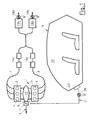
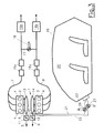
- At least one exhaust aftertreatment device 15a, 16a and at least one end silencer 15b, 16b are arranged in each outlet branch 7, 8.
- Fig. 1 and Fig. 4 show embodiments in which the groups 2, 3 of cylinders 4 are connected to a single inlet manifold 13 of an inlet strand 5.
- Fig. 3 and Fig. 5 illustrated variants each group 2, 3 of cylinders 4, each with an inlet header 13, 14 of a separate inlet strand 5, 6 connected.
- At least one inlet branch 5, 6 is acoustically connected to the interior 20 of the vehicle 19 via at least one sound-conducting device 21, 22, for example a sound tube, wherein in the exemplary embodiments the sound-conducting device 21, 22 in the area the bulkhead 23 of the vehicle 19 ends.
- the sound-conducting device 21, 22 may have an acoustic switching device 26, 27, with which the acoustic connection between the intake manifold 5, 6 and the interior 20 of the vehicle 19 optionally - in partially deactivated cylinders 4 - made or - in all activated cylinders 4 - separated can be.
- the sound-conducting device 21, 22 is advantageously from a portion of the inlet strand 5, 6 between the throttle valve 11, 12, and the intake manifold 13, 14, particularly advantageously from the region of the intake port 9, 10 of the intake manifold 13, 14, from.
- the acoustic impression of an internal combustion engine 1 operating with all cylinders 4 is generated by the sound-conducting device 21, 22 in the interior 20 of the vehicle 19.
- the rear mufflers 15, 16 can be connected by means of a switching element 18 formed for example by an exhaust flap in a connecting line 17, as in Fig. 3 is shown.
- a switching element 18 formed for example by an exhaust flap in a connecting line 17, as in Fig. 3 is shown.
- the sections joining and again separating exhaust lines 7, 8 downstream of the muffler throttle bodies 18a, 18b may be arranged be.
- the exhaust muzzle noise can thus be damped by throttling.
- the pressure pulses in the inlet branch 5, 6 are amplified by means of the sound-conducting device 21, 22 for the generation of the internal noise. This is possible because the inlet-side pressure pulses are only very slightly influenced by the electronically controlled cylinder deactivation. In this case 4 air is enforced in the deactivated group of cylinders 4.
- the inlet noise is directed into the region of the bulkhead 23 or into the region of the interior 20 of the vehicle 19 and optionally even amplified in certain frequency ranges.
- Fig. 4 and Fig. 5 show embodiments of the invention, each with a supercharged internal combustion engine 1, wherein in each intake branch 5a, 6a and 5, 6, a compressor 24a, 25a of an exhaust gas turbocharger 24, 25 is arranged.
- the exhaust gas turbines of the exhaust gas turbochargers 24, 25 are designated by reference numerals 24b and 25b.
- the sound-conducting device 21, 22 from the high-pressure part of the inlet strand 5, 6 between the compressor 24, 25 and inlet manifold 13, 14 goes out. In this way, even with supercharged internal combustion engines 1, the pressure pulses in the intake branch 5, 6 can be used optimally for generating an appealing noise in the interior 20 of the vehicle 19.
- Fig. 1 shows embodiments of the invention, each with a supercharged internal combustion engine 1, wherein in each intake branch 5a, 6a and 5, 6, a compressor 24a, 25a of an exhaust gas turbocharger 24, 25 is arranged.
- the exhaust gas turbines of the exhaust gas turbochargers 24, 25 are designated by
- the two inlet strands 5a, 6a join downstream of intercoolers 26, 27 to form a single inlet branch 5, which leads into an inlet header 13 common to both groups 2, 3 of cylinders 4. From the intake port 9 of the intake manifold 13 is a leading to the interior 20 of the vehicle 19 sound conducting device 21 goes out.
- the two inlet strands 5, 6 are also designed downstream of the intercoolers 26, 27 completely separate from each other, wherein from each inlet strand 5, 6 a sound conducting device 21, 22 emanates.
Landscapes
- Engineering & Computer Science (AREA)
- Chemical & Material Sciences (AREA)
- Combustion & Propulsion (AREA)
- Mechanical Engineering (AREA)
- General Engineering & Computer Science (AREA)
- Output Control And Ontrol Of Special Type Engine (AREA)
- Exhaust Silencers (AREA)
- Cooling, Air Intake And Gas Exhaust, And Fuel Tank Arrangements In Propulsion Units (AREA)
Description
- Die Erfindung betrifft eine Brennkraftmaschine mit zumindest zwei Zylindern oder zumindest zwei Gruppen von Zylindern, von denen zumindest einer elektronisch abschaltbar ist, mit zumindest einem Einlassstrang und zumindest einem Auslassstrang. Weiters betrifft die Erfindung ein Verfahren zum Betreiben einer Brennkraftmaschine mit zumindest zwei Zylindern oder zumindest zwei Gruppen von Zylindern, von denen zumindest einer in zumindest einem Motorbetriebsbereich abgeschaltet wird.
- Die
EP 1 564 384 offenbart ein Antriebssystem mit einer Brennkraftmaschine mit mehreren abschaltbaren Zylindern. Die Brennkraftmaschine weist einen Schalldämpfer mit einem Ventil auf, welches über einen elektronischen Aktuator ansteuerbar ist, wobei das Ventil zwischen einer offenen Stellung und einer geschlossenen Stellung umschaltbar ist. Die offene Stellung entspricht dabei einem V-8-Modus und die geschlossene Stellung einem 4-Reihenzylinder-Modus. Ähnliche Veröffentlichungen einer die Schallabstrahlung beeinflussenden Abgasklappe im Abgasstrang einer Brennkraftmaschine mit abschaltbaren Zylindern sind aus den VeröffentlichungenEP 1 561 917 A1 undDE 10 2004/046184 A1 bekannt. - Weiters beschreibt die
US 2003/066503 A eine Brennkraftmaschine mit zwei Gruppen von Zylindern, welche jeweils mit einem Einlassstrang verbunden sind. Jeder Einlassstrang weist einen Einlasssammler auf, wobei jeder Einlasssammler jeweils über eine Drosselklappe mit einem Einlassstutzen verbunden ist. In einem Betriebsbereich, in welchem die Zylinder der zweiten Gruppe abgeschaltet sind, wird Luft über die erste Drosselklappe dem ersten Einlasssammler zugeführt. Wird mehr Leistung angefordert, so kann die zweite Zylinderbank aktiviert werden, wobei Luft über die zweite Drosselklappe dem zweiten Einlasssammler zugeführt wird. Die beiden Einlassstränge sind dabei so ausgelegt, dass im Betrieb mit allen Zylindern eine teilweise Auslöschung der Ansauggeräusche erfolgt, sodass die Schallabstrahlung im Betrieb mit allen Zylindern etwa der Schallabstrahlung im Betrieb mit teilweise abgeschalteten Zylindern entspricht. - Aus der
AT 502 872 A2 - Die
JP 2005-299 505 - Die
DE 10 116 169 A1 beschreibt eine Schallübertragungsvorrichtung für ein Kraftfahrzeug zur gezielten Schallübertragung von einem Ansaugtrakt einer Brennkraftmaschine zu einem Innenraum des Kraftfahrzeuges, mit einer hohlen Übertragungsleitung, die mit einem Eingangsende mit dem Ansaugtrakt kommunizierend verbunden ist. Die hohle Übertragungsleitung strahlt am Ausgangsende den Schall zum Fahrzeuginnenraum ab und weist eine schwingungsfähige Membran auf. - Die
DE 20 2007 015 940 U1 behandelt eine Vorrichtung zur Geräuschübertragung in einem Kraftfahrzeug mit Brennkraftmaschine, mit einer Schwingungseinheit, der über eine Kommunikationsleitung der Druck aus dem Ansaugtrakt der Brennkraftmaschine zuführbar ist, und die mit dem Fahrgastraum des Kraftfahrzeugs in Verbindung steht. Ein den Querschnitt der Kommunikationsleitung einstellendes Ventil ist dabei vorgesehen, wobei die Stellung des Ventilgliedes über den Druck im Ansaugtrakt einstellbar ist. - Die
DE 19 704 376 A1 zeigt eine akustische Verbindung zwischen der Luftfilteranordnung eines Verbrennungsmotors, eines Kraftfahrzeuges und dem Innenraum des Kraftfahrzeuges, damit der Fahrer bei einem geräuscharmen Fahrzeug eine akustische Information über den Betriebszustand des Motors erhält. - Die
GB 2 423 794 A - Bei der Zylinderabschaltung bei einer Brennkraftmaschine mit zum Beispiel sechs V-förmig angeordneten Zylindern läuft der Motor während der Abschaltung von zum Beispiel einer Zylinderbank im Teillastbereich nur mit drei Zylindern. Das hat zur Folge, dass aufgrund der drei fehlenden Zündungen (bezogen auf 720° Kurbelwellenumdrehung) der Geräuschcharakter eines Drei-Zylinder-Motors entsteht. Dies ist jedoch in Oberklassefahrzeugen nicht erwünscht und teilweise ein Kriterium gegen einen Fahrzeugkauf.
- Aufgabe der Erfindung ist es, diesen Nachteil zu vermeiden und das Innenraumgeräusch des Fahrzeuges bei einer Brennkraftmaschine der eingangs genannten Art zu verbessern.
- Erfindungsgemäß wird dies dadurch erreicht dass zumindest ein Einlassstrang zumindest eines deaktivierten Zylinders über zumindest eine schallleitende Einrichtung mit einem Innenraum eines Fahrzeuges akustisch verbindbar ist, wobei zumindest der Zylinder der Brennkraftmaschine ohne Deaktivierung der Ein- und Auslassventile deaktivierbar ist.
- Bei der mechanischen Zylinderabschaltung werden die Ein- und Auslassventile der abgeschalteten Zylinder deaktiviert. Dadurch ergibt sich sowohl auf der Einlassseite als auch auf der Auslassseite eine Änderung der Geräuschcharakteristik. Bei der rein elektronischen Zylinderabschaltung ohne Schließen der Ventile bleibt die Ansauggeräuschcharakteristik wegen der auch bei abgeschalteten Zylindern nahezu unveränderten Luftmasse im Abschaltbetrieb nahezu unverändert, wohingegen die Abgasakustik wegen der fehlenden Zündungen an den abgeschalteten Zylindern ihre Charakteristik ändert. Bei der vorliegenden Erfindung wird dieser Effekt der gleichbleibenden Ansaugakustik ausgenützt und verstärkt. Vorzugsweise ist vorgesehen, dass die schallleitende Einrichtung zumindest eine akustische Schalteinrichtung aufweist, mit welcher der Einlassstrang des zumindest einen deaktivierten Zylinders akustisch mit dem Innenraum des Fahrzeuges verbunden werden kann. Der Innenraum des Fahrzeuges kann über die schallleitende Einrichtung vom Einlassstrang akustisch getrennt werden, sobald der zumindest eine deaktivierte Zylinder wieder aktiviert wird.
- Besonders vorteilhaft ist es, wenn die schallleitende Einrichtung vom Bereich einer Ansaugmündung des Einlasssammlers ausgeht.
- Bei aufgeladenen Brennkraftmaschinen geht vorzugsweise die schallleitende Einrichtung vom Hochdruckteil des Einlassstranges stromabwärts eines Verdichters, vorzugsweise zwischen einem Ladeluftkühler und einem Einlasssammler aus.
- Durch die beschriebenen Maßnahmen wird während der Zylinderabschaltung im Fahrzeuginnenraum der akustische Eindruck einer mit sämtlichen Zylindern arbeitenden Brennkraftmaschine generiert. Um dies zu erreichen, wird der Beitrag des Auspuffgeräusches im Fahrzeuginnenraum durch die Verwendung beider Endschalldämpfer-Volumina so gering wie möglich gehalten. Weiters kann das Auspuffmündungsgeräusch durch Drosselung gedämpft werden. Dabei wird ein Teil des freien Querschnittes der Abgasanlage einer oder beider Gruppen von Zylindern versperrt. Durch den kleineren, für den Volllastdurchsatz ausgelegten, Querschnitt sinkt das Mündungsgeräusch. Die Endschalldämpfer-Volumina können dabei mittels einer Abgasklappe geschalten werden. Zusätzlich werden die Druckpulse im Einlassstrang mittels der schallleitenden Einrichtung verstärkt für die Generierung des Innengeräusches herangezogen. Dies ist möglich, da die einlassseitigen Druckpulse durch die elektronisch gesteuerte Zylinderabschaltung nur sehr gering beeinflusst werden. Dabei wird auch in der abgeschalteten Zylinderbank Luft durchgesetzt. Durch den Einsatz der schallleitenden Einrichtung wird das Einlassgeräusch in den Bereich der Spritzwand bzw. in den Bereich des Fahrzeuginnenraums geleitet und gegebenenfalls in gewissen Frequenzbereichen sogar verstärkt.
- Die schallleitende Einrichtung kann beispielsweise durch ein Schallrohr (Soundpipe) gebildet sein, welches beispielsweise im Bereich der Spritzwand des Fahrzeuges endet bzw. über eine Membran mit dem Innenraum des Fahrzeuges akustisch verbunden ist.
- Die Erfindung wird im Folgenden anhand der Figuren näher erläutert. Es zeigen schematisch:
- Fig. 1
- eine erfindungsgemäße Brennkraftmaschine in einer ersten Ausführungsvariante;
- Fig. 2
- eine erfindungsgemäße Brennkraftmaschine in einer zweiten Ausführungsvariante;
- Fig. 3
- eine erfindungsgemäße Brennkraftmaschine in einer dritten Ausführungsvariante;
- Fig. 4
- eine erfindungsgemäße Brennkraftmaschine in einer vierten Ausführungsvariante; und
- Fig. 5
- eine erfindungsgemäße Brennkraftmaschine in einer fünften Ausführungsvariante.
- Funktionsgleiche Teile sind in den Ausführungsvarianten mit gleichen Bezugszeichen versehen.
- Die Figuren zeigen schematisch jeweils eine Brennkraftmaschine 1 mit sechs Zylindern 4, welche in zwei Gruppen 2, 3 angeordnet sind, wobei jede der Gruppen 2, 3 mit einem Auslassstrang 7, 8 verbunden ist. In jedem Auslassstrang 7, 8 ist mindestens eine Abgasnachbehandlungseinrichtung 15a, 16a und zumindest ein Endschalldämpfer 15b, 16b angeordnet.
- Die
Fig. 1 undFig. 4 zeigen Ausführungen, bei denen die Gruppen 2, 3 von Zylindern 4 mit einem einzigen Einlasssammler 13 eines Einlassstranges 5 verbunden sind. - Dagegen ist bei den in den
Fig. 2 ,Fig. 3 undFig. 5 dargestellten Ausführungsvarianten jede Gruppe 2, 3 von Zylindern 4 mit jeweils einem Einlasssammler 13, 14 eines separaten Einlassstranges 5, 6 verbunden. - Um das Innenraumgeräusch eines Fahrzeuges zu verbessern, ist zumindest ein Einlassstrang 5, 6 über zumindest eine schallleitende Einrichtung 21, 22, beispielsweise ein Schallrohr, mit dem Innenraum 20 des Fahrzeuges 19 akustisch verbunden, wobei in den Ausführungsbeispielen die schallleitende Einrichtung 21, 22 im Bereich der Spritzwand 23 des Fahrzeuges 19 endet. Die schallleitende Einrichtung 21, 22 kann dabei eine akustische Schalteinrichtung 26, 27 aufweisen, mit welcher die akustische Verbindung zwischen Einlassstrang 5, 6 und Innenraum 20 des Fahrzeugs 19 wahlweise - bei teilweise deaktivierten Zylindern 4 - hergestellt oder - bei allen aktivierten Zylindern 4 - getrennt werden kann.
- Die schallleitende Einrichtung 21, 22 geht dabei vorteilhafterweise von einem Bereich des Einlassstranges 5, 6 zwischen der Drosselklappe 11, 12, und dem Einlasssammler 13, 14, besonders vorteilhafterweise vom Bereich der Ansaugmündung 9, 10 des Einlasssammlers 13, 14, aus.
- Während der Zylinderabschaltung wird durch die schallleitende Einrichtung 21, 22 im Innenraum 20 des Fahrzeuges 19 der akustische Eindruck einer mit sämtlichen Zylindern 4 arbeitenden Brennkraftmaschine 1 generiert. Um dies zu erreichen, wird der Beitrag des Auspuffgeräusches im Innenraum 20 durch die Verwendung der Volumina beider Endschalldämpfer 15, 16 so gering wie möglich gehalten. Die Endschalldämpfer 15, 16 können dabei mittels eines beispielsweise durch eine Abgasklappe gebildeten Schaltorganes 18 in einer Verbindungsleitung 17 geschalten werden, wie in
Fig. 3 dargestellt ist. Bei abschnittsweise sich abschnittsweise sich vereinigenden und wieder trennenden Abgassträngen 7, 8 können auch stromabwärts der Schalldämpfer Drosselorgane 18a, 18b angeordnet sein. Das Auspuffmündungsgeräusch kann somit durch Drosselung gedämpft werden. Dabei wird ein Teil des freien Querschnittes eines oder beider Abgasstränge 7, 8 versperrt. Durch den kleineren (für Volllast ausgelegten) Querschnitt sinkt das Auspuffmündungsgeräusch. Zusätzlich werden die Druckpulse im Einlassstrang 5, 6 mittels der schallleitenden Einrichtung 21, 22 verstärkt für die Generierung des Innengeräusches herangezogen. Dies ist möglich, da die einlassseitigen Druckpulse durch die elektronisch gesteuerte Zylinderabschaltung nur sehr gering beeinflusst werden. Dabei wird auch in der abgeschalteten Gruppe 3 von Zylindern 4 Luft durchgesetzt. Durch den Einsatz der schallleitenden Einrichtung 21, 22 wird das Einlassgeräusch in den Bereich der Spritzwand 23 bzw. in den Bereich des Innenraums 20 des Fahrzeug 19 geleitet und gegebenenfalls in gewissen Frequenzbereichen sogar verstärkt. - Die
Fig. 4 undFig. 5 zeigen Ausführungen der Erfindung mit jeweils einer aufgeladenen Brennkraftmaschine 1, wobei in jedem Einlassstrang 5a, 6a bzw. 5, 6 ein Verdichter 24a, 25a eines Abgasturboladers 24, 25 angeordnet ist. Die Abgasturbinen der Abgasturbolader 24, 25 sind mit Bezugszeichen 24b bzw. 25b bezeichnet. Bei aufgeladenen Brennkraftmaschinen 1 geht die schallleitende Einrichtung 21, 22 vom Hochdruckteil des Einlassstranges 5, 6 zwischen Verdichter 24, 25 und Einlasssammler 13, 14 aus. Auf diese Weise können auch bei aufgeladenen Brennkraftmaschinen 1 die Druckpulse im Einlassstrang 5, 6 optimal zur Generierung eines ansprechenden Geräusches im Innenraum 20 des Fahrzeuges 19 genutzt werden. InFig. 4 vereinigen sich dabei die beiden Einlassstränge 5a, 6a stromabwärts von Ladeluftkühlern 26, 27 zu einem einzigen Einlassstrang 5, welcher in einen für beide Gruppen 2, 3 von Zylindern 4 gemeinsamen Einlasssammler 13 führt. Von der Ansaugmündung 9 des Einlasssammlers 13 geht eine zum Innenraum 20 des Fahrzeuges 19 führende schallleitende Einrichtung 21 aus. Bei der Ausführung nachFig. 5 dagegen sind die beiden Einlassstränge 5, 6 auch stromabwärts der Ladeluftkühler 26, 27 vollkommen getrennt voneinander ausgeführt, wobei von jedem Einlassstrang 5, 6 eine schallleitende Einrichtung 21, 22 ausgeht.
Claims (14)
- Brennkraftmaschine (1) mit zumindest zwei Zylindern (4) oder zumindest zwei Gruppen (2, 3) von Zylindern (4), von denen zumindest einer elektronisch deaktivierbar ist, mit zumindest einem Einlassstrang (5, 6) und zumindest einem Auslassstrang (7, 8), dadurch gekennzeichnet, dass zumindest ein Einlassstrang (5, 6) zumindest eines deaktivierten Zylinders (4) über zumindest eine schallleitende Einrichtung (21, 22) mit einem Innenraum (20) eines Fahrzeuges (19) akustisch verbindbar ist, wobei zumindest dieser Zylinder (4) der Brennkraftmaschine (1) ohne Deaktivierung der Ein- und Auslassventile deaktivierbar ist.
- Brennkraftmaschine (1) nach Anspruch 1, dadurch gekennzeichnet, dass die schallleitende Einrichtung (21, 22) vom Bereich einer Ansaugmündung (9, 10) eines Einlasssammlers (13, 14) ausgeht.
- Brennkraftmaschine (1) nach Anspruch 1 oder 2, dadurch gekennzeichnet, dass die schallleitende Einrichtung (21, 22) zwischen einer Drosselklappe (11, 12) und einem Einlasssammler (13, 14) vom Einlassstrang (5, 6) ausgeht.
- Brennkraftmaschine (1) nach einem der Ansprüche 1 bis 3, dadurch gekennzeichnet, dass die schallleitende Einrichtung (21, 22) von einem stromabwärts eines Verdichters (24a, 25a) angeordneten Hochdruckteil des Einlassstranges (5, 6), vorzugsweise zwischen einem Ladeluftkühler (26, 27) und einem im Einlassstrang (5, 6) angeordneten Einlasssammler (13, 14), ausgeht.
- Brennkraftmaschine (1) nach einem der Ansprüche 1 bis 4, dadurch gekennzeichnet, dass die schallleitende Einrichtung (21, 22) in den Innenraum (20) des Fahrzeugs (19) mündet.
- Brennkraftmaschine (1) nach einem der Ansprüche 1 bis 5, dadurch gekennzeichnet, dass die schallleitende Einrichtung (21, 22) im Bereich einer an den Innenraum (20) des Fahrzeuges (19) grenzenden Wand, vorzugsweise im Bereich einer Spritzwand (23), endet.
- Brennkraftmaschine (1) nach einem der Ansprüche 1 bis 6, dadurch gekennzeichnet, dass die schallleitende Einrichtung (21, 22) durch ein Schallrohr gebildet ist.
- Brennkraftmaschine (1) nach einem der Ansprüche 1 bis 7, mit zumindest zwei Auslasssträngen (7, 8), dadurch gekennzeichnet, dass zumindest zwei Auslassstränge (7, 8) über zumindest ein Schaltorgan (18) miteinander strömungsverbindbar sind.
- Brennkraftmaschine (1) nach einem der Ansprüche 1 bis 8, mit zumindest zwei Auslasssträngen (7, 8), dadurch gekennzeichnet, dass zumindest ein Auslassstrang (7, 8) zumindest ein Drosselorgan (18a, 18b) zur Reduzierung des Auslassquerschnittes aufweist.
- Brennkraftmaschine (1) nach einem der Ansprüche 1 bis 9, dadurch gekennzeichnet, dass die schallleitende Einrichtung (21, 22) eine akustische Schalteinrichtung (26, 27) aufweist.
- Verfahren zum Betreiben einer Brennkraftmaschine (1) mit zumindest zwei Zylindern (4) oder zumindest zwei Gruppen (2, 3) von Zylindern (4), von denen zumindest einer in zumindest einem Motorbetriebsbereich abgeschaltet wird, dadurch gekennzeichnet, dass zumindest während der Zylinderabschaltung zumindest ein Einlassstrang (5, 6) zumindest eines deaktivierten Zylinders (4) über eine schallleitende Einrichtung (21, 22) mit einem Innenraum (20) eines Fahrzeuges (19) akustisch verbunden wird, wobei während der Zylinderabschaltung die Einlassventile und Auslassventile des deaktivierten Zylinders (4) weiter motorbetriebsmäßig betätigt werden.
- Verfahren nach Anspruch 11 , dadurch gekennzeichnet, dass der Innenraum (20) des Fahrzeuges (19) über die schallleitende Einrichtung (21, 22) vom Einlassstrang (5, 6) akustisch getrennt wird, sobald der zumindest eine deaktivierte Zylinder (4) wieder aktiviert wird.
- Verfahren nach Anspruch 11 oder 12, wobei das Abgas zumindest zweier Zylinder (4) über zumindest zwei separate Auslassstränge (7, 8) emittiert wird, dadurch gekennzeichnet, dass während der Zylinderabschaltung die Auslassstränge (7, 8) über zumindest ein Schaltorgan (18) miteinander strömungsverbunden werden.
- Verfahren nach einem der Ansprüche 11 bis 13, wobei das Abgas zumindest zweier Zylinder (4) über zumindest zwei separate Auslassstränge (7, 8) emittiert wird, dadurch gekennzeichnet, dass während der Zylinderabschaltung die Strömung in zumindest einem Auslassstränge (7, 8) über zumindest ein Drosselorgan (18a, 18b) gedrosselt wird.
Applications Claiming Priority (2)
| Application Number | Priority Date | Filing Date | Title |
|---|---|---|---|
| AT0015610A AT507516B1 (de) | 2010-02-04 | 2010-02-04 | Brennkraftmaschine mit zylinderabschaltung |
| PCT/EP2011/050591 WO2011095390A1 (de) | 2010-02-04 | 2011-01-18 | Brennkraftmaschine mit zylinderabschaltung |
Publications (2)
| Publication Number | Publication Date |
|---|---|
| EP2531710A1 EP2531710A1 (de) | 2012-12-12 |
| EP2531710B1 true EP2531710B1 (de) | 2015-04-15 |
Family
ID=42140250
Family Applications (1)
| Application Number | Title | Priority Date | Filing Date |
|---|---|---|---|
| EP11701226.0A Not-in-force EP2531710B1 (de) | 2010-02-04 | 2011-01-18 | Brennkraftmaschine mit zylinderabschaltung |
Country Status (6)
| Country | Link |
|---|---|
| US (1) | US20130037005A1 (de) |
| EP (1) | EP2531710B1 (de) |
| JP (1) | JP2013519028A (de) |
| CN (1) | CN102770639B (de) |
| AT (1) | AT507516B1 (de) |
| WO (1) | WO2011095390A1 (de) |
Cited By (1)
| Publication number | Priority date | Publication date | Assignee | Title |
|---|---|---|---|---|
| DE102015121499A1 (de) * | 2015-12-10 | 2017-06-14 | Dr. Ing. H.C. F. Porsche Aktiengesellschaft | Geräuschübertragungssystem für ein Kraftfahrzeug |
Families Citing this family (10)
| Publication number | Priority date | Publication date | Assignee | Title |
|---|---|---|---|---|
| US10443515B2 (en) * | 2012-06-13 | 2019-10-15 | Ford Global Technologies, Llc | Internal combustion engine featuring partial shutdown and method for operating an internal combustion engine of this kind |
| US9897000B2 (en) * | 2012-11-02 | 2018-02-20 | GM Global Technology Operations LLC | Exhaust compound internal combustion engine with controlled expansion |
| US10400691B2 (en) | 2013-10-09 | 2019-09-03 | Tula Technology, Inc. | Noise/vibration reduction control |
| WO2015054412A1 (en) * | 2013-10-09 | 2015-04-16 | Tula Technology, Inc. | Noise/vibration reduction control |
| US9874161B2 (en) * | 2014-05-09 | 2018-01-23 | Ford Global Technologies, Llc | Exhaust-gas-turbocharged applied-ignition internal combustion engine having at least two turbines, and method for operating an internal combustion engine of said type |
| JP6564256B2 (ja) * | 2015-06-19 | 2019-08-21 | 株式会社Subaru | 内燃機関 |
| DE102015111297A1 (de) | 2015-07-13 | 2017-01-19 | Dr. Ing. H.C. F. Porsche Aktiengesellschaft | Geräuschübertragungssystem für ein Kraftfahrzeug |
| DE102016207037A1 (de) * | 2016-04-26 | 2017-10-26 | Bayerische Motoren Werke Aktiengesellschaft | Verfahren und Vorrichtung zum Betrieb eines einen elektrischen Energiespeicher aufweisenden Hybridfahrzeuges mit einem Elektromotor und mit einem Verbrennungsmotor |
| US10493836B2 (en) | 2018-02-12 | 2019-12-03 | Tula Technology, Inc. | Noise/vibration control using variable spring absorber |
| US11680503B2 (en) * | 2021-03-16 | 2023-06-20 | Ford Global Technologies, Llc | Exhaust sound tuning system and method |
Family Cites Families (30)
| Publication number | Priority date | Publication date | Assignee | Title |
|---|---|---|---|---|
| DE19704376A1 (de) | 1997-02-06 | 1998-08-13 | Knecht Filterwerke Gmbh | Luftfilteranordnung |
| JP2000045895A (ja) * | 1998-07-23 | 2000-02-15 | Toyota Motor Corp | エンジン音色強調装置 |
| DE10116169C2 (de) * | 2001-03-31 | 2003-11-06 | Mahle Filtersysteme Gmbh | Schallübertragungsvorrichtung für ein Kraftfahrzeug |
| US6691665B2 (en) * | 2001-10-05 | 2004-02-17 | Ford Global Technologies, Llc | Dual air induction arrangement |
| US6925982B2 (en) * | 2002-06-04 | 2005-08-09 | Ford Global Technologies, Llc | Overall scheduling of a lean burn engine system |
| US20030230272A1 (en) * | 2002-06-18 | 2003-12-18 | Siemens Vdo Automotive, Inc. | Valve actuation inlet noise control system |
| US7090048B2 (en) * | 2003-09-26 | 2006-08-15 | General Motors Corporation | Method and apparatus for exhaust sound attenuation on engines with cylinder deactivation |
| US20050109024A1 (en) * | 2003-11-26 | 2005-05-26 | John Nohl | Electrically controlled exhaust valve |
| US7260467B2 (en) * | 2003-12-12 | 2007-08-21 | Ford Global Technologies, Llc | Cylinder deactivation method to minimize drivetrain torsional disturbances |
| US20050155816A1 (en) * | 2004-01-16 | 2005-07-21 | Alcini William V. | Dynamic exhaust system for advanced internal combustion engines |
| US7428947B2 (en) * | 2004-02-12 | 2008-09-30 | Emcon Technologies Llc | Electrically controlled in-muffler exhaust valve for use during cylinder deactivation |
| US7555896B2 (en) * | 2004-03-19 | 2009-07-07 | Ford Global Technologies, Llc | Cylinder deactivation for an internal combustion engine |
| US7383119B2 (en) * | 2006-04-05 | 2008-06-03 | Ford Global Technologies, Llc | Method for controlling valves during the stop of an engine having a variable event valvetrain |
| JP4279717B2 (ja) * | 2004-04-12 | 2009-06-17 | 本田技研工業株式会社 | 内燃機関の制御装置 |
| GB2423794B (en) | 2005-03-01 | 2008-09-10 | Ford Global Tech Llc | An internal combustion engine having cylinder disablement and gas recirculation |
| US7225782B2 (en) * | 2005-03-03 | 2007-06-05 | Ford Global Technologies, Llc | System and method to control transitions in the number of cylinders in a hybrid vehicle |
| ITBO20050193A1 (it) * | 2005-03-25 | 2006-09-26 | Ferrari Spa | Motore a combustione interna con spegnimento di una parte dei cilindri e relativo metodo di controllo |
| JP2006342695A (ja) * | 2005-06-08 | 2006-12-21 | Fuji Heavy Ind Ltd | 車両のパワートレーン音導入構造 |
| US8683789B2 (en) * | 2006-11-21 | 2014-04-01 | Faurecia Emissions Control Technologies | Exhaust valve assembly with intermediate position |
| AT502872B1 (de) * | 2007-03-22 | 2009-01-15 | Avl List Gmbh | Verfahren zum absenken der reibleistung im teillastbetrieb bei einer brennkraftmaschine |
| DE102007045927B4 (de) * | 2006-12-20 | 2020-03-05 | Dr. Ing. H.C. F. Porsche Aktiengesellschaft | Schallübertragungsvorrichtung |
| US7503312B2 (en) * | 2007-05-07 | 2009-03-17 | Ford Global Technologies, Llc | Differential torque operation for internal combustion engine |
| JP2009103093A (ja) * | 2007-10-25 | 2009-05-14 | Mitsubishi Fuso Truck & Bus Corp | ディーゼルエンジンの制御装置 |
| DE202007015940U1 (de) * | 2007-11-13 | 2009-03-19 | Mann+Hummel Gmbh | Vorrichtung zur Geräuschübertragung in einem Kraftfahrzeug mit Brennkraftmaschine |
| DE102008008532A1 (de) * | 2008-02-11 | 2009-08-13 | Robert Bosch Gmbh | Verfahren und Vorrichtung zur Diagnose des Betriebes einer Brennkraftmaschine |
| JP5151697B2 (ja) * | 2008-06-02 | 2013-02-27 | トヨタ自動車株式会社 | 内燃機関の制御装置 |
| US20090319160A1 (en) * | 2008-06-24 | 2009-12-24 | Callahan Joseph E | Active exhaust valve control strategy for improved fuel consumption |
| JP5048628B2 (ja) * | 2008-10-28 | 2012-10-17 | 本田技研工業株式会社 | 能動型音響制御システム |
| CN102146861A (zh) * | 2010-02-09 | 2011-08-10 | 福特环球技术公司 | 内燃发动机的进气系统和用于操作所述类型的系统的方法 |
| US8607544B2 (en) * | 2011-05-12 | 2013-12-17 | Ford Global Technologies, Llc | Methods and systems for variable displacement engine control |
-
2010
- 2010-02-04 AT AT0015610A patent/AT507516B1/de not_active IP Right Cessation
-
2011
- 2011-01-18 CN CN201180008245.3A patent/CN102770639B/zh not_active Expired - Fee Related
- 2011-01-18 EP EP11701226.0A patent/EP2531710B1/de not_active Not-in-force
- 2011-01-18 WO PCT/EP2011/050591 patent/WO2011095390A1/de not_active Ceased
- 2011-01-18 JP JP2012551568A patent/JP2013519028A/ja active Pending
- 2011-01-18 US US13/575,552 patent/US20130037005A1/en not_active Abandoned
Cited By (1)
| Publication number | Priority date | Publication date | Assignee | Title |
|---|---|---|---|---|
| DE102015121499A1 (de) * | 2015-12-10 | 2017-06-14 | Dr. Ing. H.C. F. Porsche Aktiengesellschaft | Geräuschübertragungssystem für ein Kraftfahrzeug |
Also Published As
| Publication number | Publication date |
|---|---|
| JP2013519028A (ja) | 2013-05-23 |
| WO2011095390A1 (de) | 2011-08-11 |
| CN102770639A (zh) | 2012-11-07 |
| AT507516A1 (de) | 2010-05-15 |
| EP2531710A1 (de) | 2012-12-12 |
| AT507516B1 (de) | 2011-07-15 |
| US20130037005A1 (en) | 2013-02-14 |
| CN102770639B (zh) | 2016-01-20 |
Similar Documents
| Publication | Publication Date | Title |
|---|---|---|
| EP2531710B1 (de) | Brennkraftmaschine mit zylinderabschaltung | |
| EP2000643B1 (de) | Abgasanlage | |
| EP3311009B1 (de) | Abgasanlage | |
| WO2014183978A1 (de) | Abgasanlage für eine brennkraftmaschine und verfahren zum betreiben der abgasanlage | |
| EP1394380A1 (de) | Aufladesystem für eine Brennkraftmaschine | |
| DE102015111054A1 (de) | Geräuschübertragungssystem für ein Kraftfahrzeug und Verfahren für ein Geräuschübertragungssystem | |
| DE102008048681A1 (de) | Brennkraftmaschine mit zwei Ladern und Verfahren zum Betreiben derselben | |
| DE102014116426B4 (de) | Dual-Abgassystem-Struktur für CDA-Verbrennungsmotor | |
| DE102013210464A1 (de) | Abgasanlage für eine Brennkraftmaschine und Verfahren zum Betreiben der Abgasanlage | |
| DE102017114209A1 (de) | Luft-bypassventil-steuerung | |
| AT516513A4 (de) | Motorbremsvorrichtung für eine Brennkraftmaschine sowie Verfahren zum Betreiben einer Motorbremsvorrichtung | |
| DE102018103806A1 (de) | Fahrzeug einschliesslich fahrgastraumstörungs-mitigationssystem | |
| DE102004028482B4 (de) | Brennkraftmaschine | |
| DE102012210713A1 (de) | Schall absorbierende struktur | |
| DE60013563T2 (de) | Brennkraftmaschine mit abgasrückführung | |
| EP3701131A1 (de) | Brennkraftmaschine mit einer abgasanlage | |
| DE29803183U1 (de) | Vorrichtung zum Verändern der Akustik eines Abgasschalldämpfers | |
| DE102009060357A1 (de) | Verfahren zum Betrieb einer einen Abgasturbolader aufweisenden Brennkraftmaschine und eine Brennkraftmaschine zur Durchführung des Verfahrens | |
| DE9406200U1 (de) | Bimodale Schalldämpferanlage | |
| EP0984144B1 (de) | Abgasanlage einer mehrzylindrigen Brennkraftmaschine | |
| EP1400666B1 (de) | Abgasanlage für eine Brennkraftmaschine | |
| EP1619365B1 (de) | Abgasnachbehandlung mit sequentieller Aufladung | |
| DE102010005912B4 (de) | Verfahren zur Geräuschgestaltung bei einer Verbrennungskraftmaschine | |
| DE102010053075A1 (de) | Verbrennungskraftmaschine für einen Kraftwagen | |
| EP1338772B1 (de) | Brennkraftmaschine |
Legal Events
| Date | Code | Title | Description |
|---|---|---|---|
| PUAI | Public reference made under article 153(3) epc to a published international application that has entered the european phase |
Free format text: ORIGINAL CODE: 0009012 |
|
| 17P | Request for examination filed |
Effective date: 20120717 |
|
| AK | Designated contracting states |
Kind code of ref document: A1 Designated state(s): AL AT BE BG CH CY CZ DE DK EE ES FI FR GB GR HR HU IE IS IT LI LT LU LV MC MK MT NL NO PL PT RO RS SE SI SK SM TR |
|
| DAX | Request for extension of the european patent (deleted) | ||
| 17Q | First examination report despatched |
Effective date: 20130517 |
|
| REG | Reference to a national code |
Ref country code: DE Ref legal event code: R079 Ref document number: 502011006582 Country of ref document: DE Free format text: PREVIOUS MAIN CLASS: F02D0009040000 Ipc: F02D0013060000 |
|
| GRAP | Despatch of communication of intention to grant a patent |
Free format text: ORIGINAL CODE: EPIDOSNIGR1 |
|
| RIC1 | Information provided on ipc code assigned before grant |
Ipc: F02D 13/06 20060101AFI20141111BHEP Ipc: F02D 9/04 20060101ALI20141111BHEP Ipc: F02B 29/04 20060101ALI20141111BHEP Ipc: F02M 35/12 20060101ALI20141111BHEP Ipc: F02D 17/02 20060101ALI20141111BHEP Ipc: F01N 13/10 20100101ALI20141111BHEP |
|
| INTG | Intention to grant announced |
Effective date: 20141212 |
|
| GRAS | Grant fee paid |
Free format text: ORIGINAL CODE: EPIDOSNIGR3 |
|
| GRAA | (expected) grant |
Free format text: ORIGINAL CODE: 0009210 |
|
| AK | Designated contracting states |
Kind code of ref document: B1 Designated state(s): AL AT BE BG CH CY CZ DE DK EE ES FI FR GB GR HR HU IE IS IT LI LT LU LV MC MK MT NL NO PL PT RO RS SE SI SK SM TR |
|
| REG | Reference to a national code |
Ref country code: GB Ref legal event code: FG4D Free format text: NOT ENGLISH Ref country code: CH Ref legal event code: EP |
|
| REG | Reference to a national code |
Ref country code: IE Ref legal event code: FG4D Free format text: LANGUAGE OF EP DOCUMENT: GERMAN |
|
| REG | Reference to a national code |
Ref country code: AT Ref legal event code: REF Ref document number: 722133 Country of ref document: AT Kind code of ref document: T Effective date: 20150515 |
|
| REG | Reference to a national code |
Ref country code: DE Ref legal event code: R096 Ref document number: 502011006582 Country of ref document: DE Effective date: 20150528 |
|
| REG | Reference to a national code |
Ref country code: NL Ref legal event code: VDEP Effective date: 20150415 |
|
| REG | Reference to a national code |
Ref country code: LT Ref legal event code: MG4D |
|
| PG25 | Lapsed in a contracting state [announced via postgrant information from national office to epo] |
Ref country code: NL Free format text: LAPSE BECAUSE OF FAILURE TO SUBMIT A TRANSLATION OF THE DESCRIPTION OR TO PAY THE FEE WITHIN THE PRESCRIBED TIME-LIMIT Effective date: 20150415 |
|
| PG25 | Lapsed in a contracting state [announced via postgrant information from national office to epo] |
Ref country code: PT Free format text: LAPSE BECAUSE OF FAILURE TO SUBMIT A TRANSLATION OF THE DESCRIPTION OR TO PAY THE FEE WITHIN THE PRESCRIBED TIME-LIMIT Effective date: 20150817 Ref country code: ES Free format text: LAPSE BECAUSE OF FAILURE TO SUBMIT A TRANSLATION OF THE DESCRIPTION OR TO PAY THE FEE WITHIN THE PRESCRIBED TIME-LIMIT Effective date: 20150415 Ref country code: NO Free format text: LAPSE BECAUSE OF FAILURE TO SUBMIT A TRANSLATION OF THE DESCRIPTION OR TO PAY THE FEE WITHIN THE PRESCRIBED TIME-LIMIT Effective date: 20150715 Ref country code: FI Free format text: LAPSE BECAUSE OF FAILURE TO SUBMIT A TRANSLATION OF THE DESCRIPTION OR TO PAY THE FEE WITHIN THE PRESCRIBED TIME-LIMIT Effective date: 20150415 Ref country code: HR Free format text: LAPSE BECAUSE OF FAILURE TO SUBMIT A TRANSLATION OF THE DESCRIPTION OR TO PAY THE FEE WITHIN THE PRESCRIBED TIME-LIMIT Effective date: 20150415 Ref country code: LT Free format text: LAPSE BECAUSE OF FAILURE TO SUBMIT A TRANSLATION OF THE DESCRIPTION OR TO PAY THE FEE WITHIN THE PRESCRIBED TIME-LIMIT Effective date: 20150415 |
|
| PG25 | Lapsed in a contracting state [announced via postgrant information from national office to epo] |
Ref country code: LV Free format text: LAPSE BECAUSE OF FAILURE TO SUBMIT A TRANSLATION OF THE DESCRIPTION OR TO PAY THE FEE WITHIN THE PRESCRIBED TIME-LIMIT Effective date: 20150415 Ref country code: GR Free format text: LAPSE BECAUSE OF FAILURE TO SUBMIT A TRANSLATION OF THE DESCRIPTION OR TO PAY THE FEE WITHIN THE PRESCRIBED TIME-LIMIT Effective date: 20150716 Ref country code: IS Free format text: LAPSE BECAUSE OF FAILURE TO SUBMIT A TRANSLATION OF THE DESCRIPTION OR TO PAY THE FEE WITHIN THE PRESCRIBED TIME-LIMIT Effective date: 20150815 Ref country code: RS Free format text: LAPSE BECAUSE OF FAILURE TO SUBMIT A TRANSLATION OF THE DESCRIPTION OR TO PAY THE FEE WITHIN THE PRESCRIBED TIME-LIMIT Effective date: 20150415 |
|
| REG | Reference to a national code |
Ref country code: DE Ref legal event code: R097 Ref document number: 502011006582 Country of ref document: DE |
|
| REG | Reference to a national code |
Ref country code: FR Ref legal event code: PLFP Year of fee payment: 6 |
|
| PG25 | Lapsed in a contracting state [announced via postgrant information from national office to epo] |
Ref country code: DK Free format text: LAPSE BECAUSE OF FAILURE TO SUBMIT A TRANSLATION OF THE DESCRIPTION OR TO PAY THE FEE WITHIN THE PRESCRIBED TIME-LIMIT Effective date: 20150415 Ref country code: EE Free format text: LAPSE BECAUSE OF FAILURE TO SUBMIT A TRANSLATION OF THE DESCRIPTION OR TO PAY THE FEE WITHIN THE PRESCRIBED TIME-LIMIT Effective date: 20150415 |
|
| PLBE | No opposition filed within time limit |
Free format text: ORIGINAL CODE: 0009261 |
|
| STAA | Information on the status of an ep patent application or granted ep patent |
Free format text: STATUS: NO OPPOSITION FILED WITHIN TIME LIMIT |
|
| PG25 | Lapsed in a contracting state [announced via postgrant information from national office to epo] |
Ref country code: RO Free format text: LAPSE BECAUSE OF NON-PAYMENT OF DUE FEES Effective date: 20150415 Ref country code: PL Free format text: LAPSE BECAUSE OF FAILURE TO SUBMIT A TRANSLATION OF THE DESCRIPTION OR TO PAY THE FEE WITHIN THE PRESCRIBED TIME-LIMIT Effective date: 20150415 Ref country code: SK Free format text: LAPSE BECAUSE OF FAILURE TO SUBMIT A TRANSLATION OF THE DESCRIPTION OR TO PAY THE FEE WITHIN THE PRESCRIBED TIME-LIMIT Effective date: 20150415 Ref country code: CZ Free format text: LAPSE BECAUSE OF FAILURE TO SUBMIT A TRANSLATION OF THE DESCRIPTION OR TO PAY THE FEE WITHIN THE PRESCRIBED TIME-LIMIT Effective date: 20150415 |
|
| 26N | No opposition filed |
Effective date: 20160118 |
|
| PG25 | Lapsed in a contracting state [announced via postgrant information from national office to epo] |
Ref country code: SI Free format text: LAPSE BECAUSE OF FAILURE TO SUBMIT A TRANSLATION OF THE DESCRIPTION OR TO PAY THE FEE WITHIN THE PRESCRIBED TIME-LIMIT Effective date: 20150415 Ref country code: BE Free format text: LAPSE BECAUSE OF NON-PAYMENT OF DUE FEES Effective date: 20160131 |
|
| PG25 | Lapsed in a contracting state [announced via postgrant information from national office to epo] |
Ref country code: LU Free format text: LAPSE BECAUSE OF FAILURE TO SUBMIT A TRANSLATION OF THE DESCRIPTION OR TO PAY THE FEE WITHIN THE PRESCRIBED TIME-LIMIT Effective date: 20160118 |
|
| REG | Reference to a national code |
Ref country code: CH Ref legal event code: PL |
|
| PG25 | Lapsed in a contracting state [announced via postgrant information from national office to epo] |
Ref country code: MC Free format text: LAPSE BECAUSE OF FAILURE TO SUBMIT A TRANSLATION OF THE DESCRIPTION OR TO PAY THE FEE WITHIN THE PRESCRIBED TIME-LIMIT Effective date: 20150415 |
|
| PG25 | Lapsed in a contracting state [announced via postgrant information from national office to epo] |
Ref country code: CH Free format text: LAPSE BECAUSE OF NON-PAYMENT OF DUE FEES Effective date: 20160131 Ref country code: LI Free format text: LAPSE BECAUSE OF NON-PAYMENT OF DUE FEES Effective date: 20160131 |
|
| REG | Reference to a national code |
Ref country code: IE Ref legal event code: MM4A |
|
| PG25 | Lapsed in a contracting state [announced via postgrant information from national office to epo] |
Ref country code: IE Free format text: LAPSE BECAUSE OF NON-PAYMENT OF DUE FEES Effective date: 20160118 |
|
| REG | Reference to a national code |
Ref country code: FR Ref legal event code: PLFP Year of fee payment: 7 |
|
| REG | Reference to a national code |
Ref country code: AT Ref legal event code: MM01 Ref document number: 722133 Country of ref document: AT Kind code of ref document: T Effective date: 20160118 |
|
| PGFP | Annual fee paid to national office [announced via postgrant information from national office to epo] |
Ref country code: FR Payment date: 20170131 Year of fee payment: 7 Ref country code: DE Payment date: 20170228 Year of fee payment: 7 |
|
| PG25 | Lapsed in a contracting state [announced via postgrant information from national office to epo] |
Ref country code: AT Free format text: LAPSE BECAUSE OF NON-PAYMENT OF DUE FEES Effective date: 20160118 |
|
| PGFP | Annual fee paid to national office [announced via postgrant information from national office to epo] |
Ref country code: GB Payment date: 20170131 Year of fee payment: 7 |
|
| PG25 | Lapsed in a contracting state [announced via postgrant information from national office to epo] |
Ref country code: SE Free format text: LAPSE BECAUSE OF FAILURE TO SUBMIT A TRANSLATION OF THE DESCRIPTION OR TO PAY THE FEE WITHIN THE PRESCRIBED TIME-LIMIT Effective date: 20150415 |
|
| PGFP | Annual fee paid to national office [announced via postgrant information from national office to epo] |
Ref country code: IT Payment date: 20170131 Year of fee payment: 7 |
|
| PG25 | Lapsed in a contracting state [announced via postgrant information from national office to epo] |
Ref country code: MT Free format text: LAPSE BECAUSE OF FAILURE TO SUBMIT A TRANSLATION OF THE DESCRIPTION OR TO PAY THE FEE WITHIN THE PRESCRIBED TIME-LIMIT Effective date: 20150415 |
|
| PG25 | Lapsed in a contracting state [announced via postgrant information from national office to epo] |
Ref country code: CY Free format text: LAPSE BECAUSE OF FAILURE TO SUBMIT A TRANSLATION OF THE DESCRIPTION OR TO PAY THE FEE WITHIN THE PRESCRIBED TIME-LIMIT Effective date: 20150415 Ref country code: SM Free format text: LAPSE BECAUSE OF FAILURE TO SUBMIT A TRANSLATION OF THE DESCRIPTION OR TO PAY THE FEE WITHIN THE PRESCRIBED TIME-LIMIT Effective date: 20150415 Ref country code: HU Free format text: LAPSE BECAUSE OF FAILURE TO SUBMIT A TRANSLATION OF THE DESCRIPTION OR TO PAY THE FEE WITHIN THE PRESCRIBED TIME-LIMIT; INVALID AB INITIO Effective date: 20110118 |
|
| PG25 | Lapsed in a contracting state [announced via postgrant information from national office to epo] |
Ref country code: MK Free format text: LAPSE BECAUSE OF FAILURE TO SUBMIT A TRANSLATION OF THE DESCRIPTION OR TO PAY THE FEE WITHIN THE PRESCRIBED TIME-LIMIT Effective date: 20150415 Ref country code: TR Free format text: LAPSE BECAUSE OF FAILURE TO SUBMIT A TRANSLATION OF THE DESCRIPTION OR TO PAY THE FEE WITHIN THE PRESCRIBED TIME-LIMIT Effective date: 20150415 |
|
| PG25 | Lapsed in a contracting state [announced via postgrant information from national office to epo] |
Ref country code: BG Free format text: LAPSE BECAUSE OF FAILURE TO SUBMIT A TRANSLATION OF THE DESCRIPTION OR TO PAY THE FEE WITHIN THE PRESCRIBED TIME-LIMIT Effective date: 20150415 |
|
| REG | Reference to a national code |
Ref country code: DE Ref legal event code: R119 Ref document number: 502011006582 Country of ref document: DE |
|
| GBPC | Gb: european patent ceased through non-payment of renewal fee |
Effective date: 20180118 |
|
| PG25 | Lapsed in a contracting state [announced via postgrant information from national office to epo] |
Ref country code: DE Free format text: LAPSE BECAUSE OF NON-PAYMENT OF DUE FEES Effective date: 20180801 Ref country code: AL Free format text: LAPSE BECAUSE OF FAILURE TO SUBMIT A TRANSLATION OF THE DESCRIPTION OR TO PAY THE FEE WITHIN THE PRESCRIBED TIME-LIMIT Effective date: 20150415 Ref country code: FR Free format text: LAPSE BECAUSE OF NON-PAYMENT OF DUE FEES Effective date: 20180131 |
|
| REG | Reference to a national code |
Ref country code: FR Ref legal event code: ST Effective date: 20180928 |
|
| PG25 | Lapsed in a contracting state [announced via postgrant information from national office to epo] |
Ref country code: GB Free format text: LAPSE BECAUSE OF NON-PAYMENT OF DUE FEES Effective date: 20180118 |
|
| PG25 | Lapsed in a contracting state [announced via postgrant information from national office to epo] |
Ref country code: IT Free format text: LAPSE BECAUSE OF NON-PAYMENT OF DUE FEES Effective date: 20180118 |