EP2531133B1 - Kombinierte ablation und ultraschallbildgebung - Google Patents
Kombinierte ablation und ultraschallbildgebung Download PDFInfo
- Publication number
- EP2531133B1 EP2531133B1 EP11708323.8A EP11708323A EP2531133B1 EP 2531133 B1 EP2531133 B1 EP 2531133B1 EP 11708323 A EP11708323 A EP 11708323A EP 2531133 B1 EP2531133 B1 EP 2531133B1
- Authority
- EP
- European Patent Office
- Prior art keywords
- ablation
- tissue
- associated tissue
- unit
- signal
- Prior art date
- Legal status (The legal status is an assumption and is not a legal conclusion. Google has not performed a legal analysis and makes no representation as to the accuracy of the status listed.)
- Not-in-force
Links
- 238000002679 ablation Methods 0.000 title claims description 120
- 238000012285 ultrasound imaging Methods 0.000 title claims description 18
- 238000002604 ultrasonography Methods 0.000 claims description 52
- 238000003973 irrigation Methods 0.000 claims description 34
- 230000002262 irrigation Effects 0.000 claims description 34
- 230000004044 response Effects 0.000 claims description 15
- 230000000451 tissue damage Effects 0.000 claims description 13
- 231100000827 tissue damage Toxicity 0.000 claims description 13
- 239000012530 fluid Substances 0.000 claims description 8
- 238000010438 heat treatment Methods 0.000 claims description 4
- 238000004590 computer program Methods 0.000 claims description 3
- 230000004807 localization Effects 0.000 claims description 2
- 210000001519 tissue Anatomy 0.000 description 75
- 238000000034 method Methods 0.000 description 28
- 230000001276 controlling effect Effects 0.000 description 27
- 230000015572 biosynthetic process Effects 0.000 description 15
- 230000008569 process Effects 0.000 description 14
- 230000008901 benefit Effects 0.000 description 11
- 230000008859 change Effects 0.000 description 9
- 238000003384 imaging method Methods 0.000 description 8
- 238000012544 monitoring process Methods 0.000 description 7
- 238000005259 measurement Methods 0.000 description 6
- 238000001514 detection method Methods 0.000 description 5
- 230000003902 lesion Effects 0.000 description 5
- 238000009826 distribution Methods 0.000 description 4
- 210000005003 heart tissue Anatomy 0.000 description 4
- 230000003287 optical effect Effects 0.000 description 4
- 241001494479 Pecora Species 0.000 description 3
- 230000000747 cardiac effect Effects 0.000 description 3
- 238000011161 development Methods 0.000 description 3
- 239000011888 foil Substances 0.000 description 3
- 229920000306 polymethylpentene Polymers 0.000 description 3
- 239000011116 polymethylpentene Substances 0.000 description 3
- 238000007674 radiofrequency ablation Methods 0.000 description 3
- 238000001574 biopsy Methods 0.000 description 2
- 210000004369 blood Anatomy 0.000 description 2
- 239000008280 blood Substances 0.000 description 2
- 238000006073 displacement reaction Methods 0.000 description 2
- 239000007788 liquid Substances 0.000 description 2
- 230000005855 radiation Effects 0.000 description 2
- 238000012800 visualization Methods 0.000 description 2
- XLYOFNOQVPJJNP-UHFFFAOYSA-N water Substances O XLYOFNOQVPJJNP-UHFFFAOYSA-N 0.000 description 2
- 206010020843 Hyperthermia Diseases 0.000 description 1
- 241001465754 Metazoa Species 0.000 description 1
- 229920002614 Polyether block amide Polymers 0.000 description 1
- FAPWRFPIFSIZLT-UHFFFAOYSA-M Sodium chloride Chemical compound [Na+].[Cl-] FAPWRFPIFSIZLT-UHFFFAOYSA-M 0.000 description 1
- 208000027418 Wounds and injury Diseases 0.000 description 1
- 238000013459 approach Methods 0.000 description 1
- 230000006793 arrhythmia Effects 0.000 description 1
- 206010003119 arrhythmia Diseases 0.000 description 1
- 230000005540 biological transmission Effects 0.000 description 1
- 230000017531 blood circulation Effects 0.000 description 1
- 238000004422 calculation algorithm Methods 0.000 description 1
- 238000004364 calculation method Methods 0.000 description 1
- 238000013153 catheter ablation Methods 0.000 description 1
- 238000012512 characterization method Methods 0.000 description 1
- 238000006243 chemical reaction Methods 0.000 description 1
- 230000008878 coupling Effects 0.000 description 1
- 238000010168 coupling process Methods 0.000 description 1
- 238000005859 coupling reaction Methods 0.000 description 1
- 230000006378 damage Effects 0.000 description 1
- 238000013500 data storage Methods 0.000 description 1
- 230000003247 decreasing effect Effects 0.000 description 1
- 238000003745 diagnosis Methods 0.000 description 1
- 230000008030 elimination Effects 0.000 description 1
- 238000003379 elimination reaction Methods 0.000 description 1
- 230000008020 evaporation Effects 0.000 description 1
- 238000001704 evaporation Methods 0.000 description 1
- 230000036031 hyperthermia Effects 0.000 description 1
- 238000010191 image analysis Methods 0.000 description 1
- 238000002847 impedance measurement Methods 0.000 description 1
- 230000006872 improvement Effects 0.000 description 1
- 238000001727 in vivo Methods 0.000 description 1
- 208000014674 injury Diseases 0.000 description 1
- 230000010354 integration Effects 0.000 description 1
- 239000000463 material Substances 0.000 description 1
- 229910052751 metal Inorganic materials 0.000 description 1
- 239000002184 metal Substances 0.000 description 1
- 238000002324 minimally invasive surgery Methods 0.000 description 1
- 210000003205 muscle Anatomy 0.000 description 1
- 230000037361 pathway Effects 0.000 description 1
- 230000035515 penetration Effects 0.000 description 1
- 238000009611 phonocardiography Methods 0.000 description 1
- BASFCYQUMIYNBI-UHFFFAOYSA-N platinum Chemical group [Pt] BASFCYQUMIYNBI-UHFFFAOYSA-N 0.000 description 1
- 238000012805 post-processing Methods 0.000 description 1
- 238000011084 recovery Methods 0.000 description 1
- 230000009467 reduction Effects 0.000 description 1
- 230000001105 regulatory effect Effects 0.000 description 1
- 230000000241 respiratory effect Effects 0.000 description 1
- 231100000241 scar Toxicity 0.000 description 1
- 239000007787 solid Substances 0.000 description 1
- 230000002123 temporal effect Effects 0.000 description 1
- 230000000007 visual effect Effects 0.000 description 1
Images


Classifications
-
- A—HUMAN NECESSITIES
- A61—MEDICAL OR VETERINARY SCIENCE; HYGIENE
- A61B—DIAGNOSIS; SURGERY; IDENTIFICATION
- A61B18/00—Surgical instruments, devices or methods for transferring non-mechanical forms of energy to or from the body
- A61B18/18—Surgical instruments, devices or methods for transferring non-mechanical forms of energy to or from the body by applying electromagnetic radiation, e.g. microwaves
-
- A—HUMAN NECESSITIES
- A61—MEDICAL OR VETERINARY SCIENCE; HYGIENE
- A61B—DIAGNOSIS; SURGERY; IDENTIFICATION
- A61B18/00—Surgical instruments, devices or methods for transferring non-mechanical forms of energy to or from the body
- A61B18/04—Surgical instruments, devices or methods for transferring non-mechanical forms of energy to or from the body by heating
- A61B18/12—Surgical instruments, devices or methods for transferring non-mechanical forms of energy to or from the body by heating by passing a current through the tissue to be heated, e.g. high-frequency current
- A61B18/14—Probes or electrodes therefor
- A61B18/1492—Probes or electrodes therefor having a flexible, catheter-like structure, e.g. for heart ablation
-
- A—HUMAN NECESSITIES
- A61—MEDICAL OR VETERINARY SCIENCE; HYGIENE
- A61B—DIAGNOSIS; SURGERY; IDENTIFICATION
- A61B17/00—Surgical instruments, devices or methods
- A61B17/34—Trocars; Puncturing needles
- A61B17/3478—Endoscopic needles, e.g. for infusion
-
- A—HUMAN NECESSITIES
- A61—MEDICAL OR VETERINARY SCIENCE; HYGIENE
- A61B—DIAGNOSIS; SURGERY; IDENTIFICATION
- A61B18/00—Surgical instruments, devices or methods for transferring non-mechanical forms of energy to or from the body
- A61B18/04—Surgical instruments, devices or methods for transferring non-mechanical forms of energy to or from the body by heating
- A61B18/12—Surgical instruments, devices or methods for transferring non-mechanical forms of energy to or from the body by heating by passing a current through the tissue to be heated, e.g. high-frequency current
- A61B18/1206—Generators therefor
-
- A—HUMAN NECESSITIES
- A61—MEDICAL OR VETERINARY SCIENCE; HYGIENE
- A61B—DIAGNOSIS; SURGERY; IDENTIFICATION
- A61B18/00—Surgical instruments, devices or methods for transferring non-mechanical forms of energy to or from the body
- A61B18/04—Surgical instruments, devices or methods for transferring non-mechanical forms of energy to or from the body by heating
- A61B18/12—Surgical instruments, devices or methods for transferring non-mechanical forms of energy to or from the body by heating by passing a current through the tissue to be heated, e.g. high-frequency current
- A61B18/14—Probes or electrodes therefor
- A61B18/1477—Needle-like probes
-
- A—HUMAN NECESSITIES
- A61—MEDICAL OR VETERINARY SCIENCE; HYGIENE
- A61B—DIAGNOSIS; SURGERY; IDENTIFICATION
- A61B18/00—Surgical instruments, devices or methods for transferring non-mechanical forms of energy to or from the body
- A61B18/18—Surgical instruments, devices or methods for transferring non-mechanical forms of energy to or from the body by applying electromagnetic radiation, e.g. microwaves
- A61B18/1815—Surgical instruments, devices or methods for transferring non-mechanical forms of energy to or from the body by applying electromagnetic radiation, e.g. microwaves using microwaves
-
- A—HUMAN NECESSITIES
- A61—MEDICAL OR VETERINARY SCIENCE; HYGIENE
- A61B—DIAGNOSIS; SURGERY; IDENTIFICATION
- A61B18/00—Surgical instruments, devices or methods for transferring non-mechanical forms of energy to or from the body
- A61B18/18—Surgical instruments, devices or methods for transferring non-mechanical forms of energy to or from the body by applying electromagnetic radiation, e.g. microwaves
- A61B18/20—Surgical instruments, devices or methods for transferring non-mechanical forms of energy to or from the body by applying electromagnetic radiation, e.g. microwaves using laser
- A61B18/22—Surgical instruments, devices or methods for transferring non-mechanical forms of energy to or from the body by applying electromagnetic radiation, e.g. microwaves using laser the beam being directed along or through a flexible conduit, e.g. an optical fibre; Couplings or hand-pieces therefor
- A61B18/24—Surgical instruments, devices or methods for transferring non-mechanical forms of energy to or from the body by applying electromagnetic radiation, e.g. microwaves using laser the beam being directed along or through a flexible conduit, e.g. an optical fibre; Couplings or hand-pieces therefor with a catheter
-
- A—HUMAN NECESSITIES
- A61—MEDICAL OR VETERINARY SCIENCE; HYGIENE
- A61B—DIAGNOSIS; SURGERY; IDENTIFICATION
- A61B17/00—Surgical instruments, devices or methods
- A61B2017/00017—Electrical control of surgical instruments
- A61B2017/00022—Sensing or detecting at the treatment site
- A61B2017/00106—Sensing or detecting at the treatment site ultrasonic
-
- A—HUMAN NECESSITIES
- A61—MEDICAL OR VETERINARY SCIENCE; HYGIENE
- A61B—DIAGNOSIS; SURGERY; IDENTIFICATION
- A61B18/00—Surgical instruments, devices or methods for transferring non-mechanical forms of energy to or from the body
- A61B2018/00005—Cooling or heating of the probe or tissue immediately surrounding the probe
- A61B2018/00011—Cooling or heating of the probe or tissue immediately surrounding the probe with fluids
- A61B2018/00029—Cooling or heating of the probe or tissue immediately surrounding the probe with fluids open
-
- A—HUMAN NECESSITIES
- A61—MEDICAL OR VETERINARY SCIENCE; HYGIENE
- A61B—DIAGNOSIS; SURGERY; IDENTIFICATION
- A61B18/00—Surgical instruments, devices or methods for transferring non-mechanical forms of energy to or from the body
- A61B2018/00315—Surgical instruments, devices or methods for transferring non-mechanical forms of energy to or from the body for treatment of particular body parts
- A61B2018/00345—Vascular system
- A61B2018/00351—Heart
-
- A—HUMAN NECESSITIES
- A61—MEDICAL OR VETERINARY SCIENCE; HYGIENE
- A61B—DIAGNOSIS; SURGERY; IDENTIFICATION
- A61B18/00—Surgical instruments, devices or methods for transferring non-mechanical forms of energy to or from the body
- A61B2018/00636—Sensing and controlling the application of energy
- A61B2018/00642—Sensing and controlling the application of energy with feedback, i.e. closed loop control
-
- A—HUMAN NECESSITIES
- A61—MEDICAL OR VETERINARY SCIENCE; HYGIENE
- A61B—DIAGNOSIS; SURGERY; IDENTIFICATION
- A61B18/00—Surgical instruments, devices or methods for transferring non-mechanical forms of energy to or from the body
- A61B2018/00636—Sensing and controlling the application of energy
- A61B2018/00666—Sensing and controlling the application of energy using a threshold value
-
- A—HUMAN NECESSITIES
- A61—MEDICAL OR VETERINARY SCIENCE; HYGIENE
- A61B—DIAGNOSIS; SURGERY; IDENTIFICATION
- A61B18/00—Surgical instruments, devices or methods for transferring non-mechanical forms of energy to or from the body
- A61B2018/00636—Sensing and controlling the application of energy
- A61B2018/00773—Sensed parameters
- A61B2018/00875—Resistance or impedance
-
- A—HUMAN NECESSITIES
- A61—MEDICAL OR VETERINARY SCIENCE; HYGIENE
- A61B—DIAGNOSIS; SURGERY; IDENTIFICATION
- A61B18/00—Surgical instruments, devices or methods for transferring non-mechanical forms of energy to or from the body
- A61B18/04—Surgical instruments, devices or methods for transferring non-mechanical forms of energy to or from the body by heating
- A61B18/12—Surgical instruments, devices or methods for transferring non-mechanical forms of energy to or from the body by heating by passing a current through the tissue to be heated, e.g. high-frequency current
- A61B18/14—Probes or electrodes therefor
- A61B2018/1405—Electrodes having a specific shape
- A61B2018/1425—Needle
-
- A—HUMAN NECESSITIES
- A61—MEDICAL OR VETERINARY SCIENCE; HYGIENE
- A61B—DIAGNOSIS; SURGERY; IDENTIFICATION
- A61B18/00—Surgical instruments, devices or methods for transferring non-mechanical forms of energy to or from the body
- A61B18/18—Surgical instruments, devices or methods for transferring non-mechanical forms of energy to or from the body by applying electromagnetic radiation, e.g. microwaves
- A61B18/1815—Surgical instruments, devices or methods for transferring non-mechanical forms of energy to or from the body by applying electromagnetic radiation, e.g. microwaves using microwaves
- A61B2018/1861—Surgical instruments, devices or methods for transferring non-mechanical forms of energy to or from the body by applying electromagnetic radiation, e.g. microwaves using microwaves with an instrument inserted into a body lumen or cavity, e.g. a catheter
-
- A—HUMAN NECESSITIES
- A61—MEDICAL OR VETERINARY SCIENCE; HYGIENE
- A61B—DIAGNOSIS; SURGERY; IDENTIFICATION
- A61B18/00—Surgical instruments, devices or methods for transferring non-mechanical forms of energy to or from the body
- A61B18/18—Surgical instruments, devices or methods for transferring non-mechanical forms of energy to or from the body by applying electromagnetic radiation, e.g. microwaves
- A61B18/1815—Surgical instruments, devices or methods for transferring non-mechanical forms of energy to or from the body by applying electromagnetic radiation, e.g. microwaves using microwaves
- A61B2018/1869—Surgical instruments, devices or methods for transferring non-mechanical forms of energy to or from the body by applying electromagnetic radiation, e.g. microwaves using microwaves with an instrument interstitially inserted into the body, e.g. needles
-
- A—HUMAN NECESSITIES
- A61—MEDICAL OR VETERINARY SCIENCE; HYGIENE
- A61B—DIAGNOSIS; SURGERY; IDENTIFICATION
- A61B90/00—Instruments, implements or accessories specially adapted for surgery or diagnosis and not covered by any of the groups A61B1/00 - A61B50/00, e.g. for luxation treatment or for protecting wound edges
- A61B90/06—Measuring instruments not otherwise provided for
- A61B2090/064—Measuring instruments not otherwise provided for for measuring force, pressure or mechanical tension
-
- A—HUMAN NECESSITIES
- A61—MEDICAL OR VETERINARY SCIENCE; HYGIENE
- A61B—DIAGNOSIS; SURGERY; IDENTIFICATION
- A61B90/00—Instruments, implements or accessories specially adapted for surgery or diagnosis and not covered by any of the groups A61B1/00 - A61B50/00, e.g. for luxation treatment or for protecting wound edges
- A61B90/36—Image-producing devices or illumination devices not otherwise provided for
- A61B90/37—Surgical systems with images on a monitor during operation
- A61B2090/378—Surgical systems with images on a monitor during operation using ultrasound
- A61B2090/3782—Surgical systems with images on a monitor during operation using ultrasound transmitter or receiver in catheter or minimal invasive instrument
- A61B2090/3784—Surgical systems with images on a monitor during operation using ultrasound transmitter or receiver in catheter or minimal invasive instrument both receiver and transmitter being in the instrument or receiver being also transmitter
-
- A—HUMAN NECESSITIES
- A61—MEDICAL OR VETERINARY SCIENCE; HYGIENE
- A61B—DIAGNOSIS; SURGERY; IDENTIFICATION
- A61B2218/00—Details of surgical instruments, devices or methods for transferring non-mechanical forms of energy to or from the body
- A61B2218/001—Details of surgical instruments, devices or methods for transferring non-mechanical forms of energy to or from the body having means for irrigation and/or aspiration of substances to and/or from the surgical site
- A61B2218/002—Irrigation
Definitions
- the present invention relates to the field of interventional devices and control units, and more specifically to a system and method for combined ablation and ultrasound imaging.
- Ablation such as ablation using a catheter
- cardiac tissue is locally affected in order to block undesired conduction pathways.
- RF radio frequency
- a lesion starts to grow through the depth of the tissue wall, which becomes non-conducting scar tissue.
- Electrophysiologists aim to create lesions that run completely through the tissue wall (i.e. transmural) and are permanent (i.e. coagulated tissue, no recovery possible).
- Tissue ablation is not without risk.
- One or more bubbles may form in the tissue during ablation, and rapid release of bubble energy can be induced.
- microbubble formation during radio frequency ablation using phonocardiography', published in Europace (2006), 8, 333-335 , discloses that characteristic acoustic signatures are present before pops and correspond to microbubble (MB) formation.
- MB microbubble
- the ability to record acoustic sounds of MB formation in vivo is not known and may be complicated by respiratory, cardiac, and muscle artefacts.
- the reference US 2005/0283074 A1 describes that bubble generation during a tissue ablation procedure is identified or detected.
- the ultrasound imaging is optimized to better detect generation of bubbles for more refined visualization and control of the ablation procedure.
- the generation of bubbles may alternatively or additionally be quantified to assist in control and/or diagnosis during an ablation procedure.
- Signals are generated based on the detection of a change in bubble characteristics. For example, the detection of type 2 or type 1 bubble generation is used to generate audio or visual warning signals. As another example, detection of type 1 or type 2 bubbles triggers generation of a control signal for increasing, decreasing or terminating the ablation energy. The generation of the control signal is performed automatically rather than relying on user visualization and reaction.
- the reference US 2009/0287205 A1 describes a system for controllably delivering ablation energy to tissue which includes an ablation device operable to supply ablation energy to body tissue causing bubbles to form in the tissue, an ultrasound transducer configured to detect energy spontaneously emitted by collapsing or shrinking bubbles that are resonating in the tissue, and a control element operably coupled to the ablation device and the ultrasound transducer element, the control element being configured to adjust the ablation energy supplied to the tissue in response to the energy detected by the ultrasound transducer to prevent tissue popping caused by bubble expansion.
- the present invention preferably seeks to alleviate or eliminate the above-mentioned disadvantages of during an ablation process.
- the invention is particularly, but not exclusively, advantageous for obtaining a safer ablation process. Electrophysiologists have indicated that it is extremely valuable to predict so-called "pops" or "tissue pops". Ablation may induce formation of one or more bubbles in the tissue during ablation, and this may lead to potentially harmful and rapid release of bubble energy. In the following, such rapid release of bubble energy is referred to as a so-called "pop” or a "tissue pop”. A prediction of an impending pop, or a knowledge of a risk of an impending tissue damage due to a rapid release of a bubble energy, may allow relevant parameters to be properly regulated in order to prevent the pop. It is expected that this would significantly increase the safety of ablation procedures. Another advantage might be that the invention devises an integrated and miniaturized device which enables safe ablation.
- acoustic signatures relating to bubbles were measured, however, these acoustic signatures related to bubbles that were formed at the interface between electrode and tissue, which is imaged by Intra Cardiac Echography (ICE).
- ICE Intra Cardiac Echography
- Gas formation at the interface can be caused by local heating of the fluid around the tip electrode, and does not necessarily relate to gas formation within the tissue.
- the ability to record acoustic sounds of microbubble formation at this interface may be complicated in a closed-chest procedure and may require the integration of a bulky microphone in a catheter.
- the ultrasound transducer in the interventional device of the present invention is preferably applied for monitoring or imaging the local cardiac tissue, the ablation process in said cardiac tissue or parameters related, directly or indirectly, to the ablation process. For example, the formation of microbubbles within the associated tissue might be monitored.
- the invention according to the 1 s t aspect may alternatively be implemented not using the indication of one or more bubbles within the associated tissue, but other characteristics in tissue. Such other parameters might include the local expansion of the associated tissue.
- monitoring is to be construed broadly. It includes both 1D monitoring, i.e. detecting reflected intensities along the line of sight as well as 2D imaging where an array of transducers are applied to generate a 2D image as well as time resolved imaging (so-called ultrasound "M-mode” imaging). In principle also 3D imaging may be obtained.
- interventional device based monitoring such as catheter based monitoring, it is presently normal to use (time resolved) 1D or 2D monitoring due to space constraints in the distal end region, i.e. in the tip region.
- ablation refers to any kind of suitable ablation within the teaching and general principle of the present invention.
- it could be radio frequency (RF) based (incl. microwave), optically based (e.g., an optical emitter, such as a laser, such as a laser emitting wavelengths in the infrared, visible or ultraviolet range), a heating element, such as a hot water balloon, or ultrasound-based ablation such as high intensity focused ultrasound (HIFU).
- RF radio frequency
- microwave optically based
- an optical emitter such as a laser, such as a laser emitting wavelengths in the infrared, visible or ultraviolet range
- a heating element such as a hot water balloon
- ultrasound-based ablation such as high intensity focused ultrasound (HIFU).
- HIFU high intensity focused ultrasound
- ablation unit refers to an optical emitter, such as a laser in case of optical-based ablation, an electrode (or other suitable RF emitting devices) in case of RF- and microwave-based ablation and to an ultrasound transducer, such as a high intensity focused ultrasound (HIFU) transducer, in case of ultrasound based ablation.
- optical emitter such as a laser in case of optical-based ablation
- electrode or other suitable RF emitting devices
- ultrasound transducer such as a high intensity focused ultrasound (HIFU) transducer
- the interventional device might be a unit wherein the ablation unit and the ultrasound transducer are integrated, however, it might also be embodied as an interventional device where the ablation unit and the ultrasound transducer are separate units.
- the interventional device might comprise a catheter, a needle, a biopsy needle, guidewire, sheath, or an endoscope.
- the ultrasonic signal might be a pulsed-echo signal.
- the pulsed-echo technique is defined as sending a short ultrasound pulse by a low-Q transducer into a medium, and receiving the reflections back at the transducer from irregularities in the medium (due to change of acoustical impedance).
- the transit time from the initial pulse transmission to reception of the echo is proportional to the depth at which the irregularities are found.
- the controlling unit may be any unit capable of sending an output signal, such as a control signal to the ultrasound transducer, and capable of receiving an input signal, such as a response signal from the ultrasound transducer, and further capable of calculating a value, such as a predictor value.
- the controlling unit can be implemented by means of hardware, such as electronic components such as transistors, operational amplifiers and similar components. It may, however, also be implanted as software, firmware or any combination of these, running on a processor.
- the predictor value is understood to be a value representative of a risk of impending tissue damage due to a rapid release of a bubble energy.
- the predictor value may be a probability of impending tissue damage due to a rapid release of a bubble energy, but it may also be a parameter, such as a measurable parameter, such as a number of bubbles, such as a volume of bubbles, such as a rate of change of the number of bubbles, which may be relevant for calculating the risk of impending tissue damage due to a rapid release of a bubble energy.
- controlling unit is further arranged to send a primary signal (RS) if the predictor value exceeds a threshold value (TV).
- RS primary signal
- TV threshold value
- the threshold may be a number set by a user or automatically set by an apparatus, for use in comparison with the predictor value.
- the threshold may vary, or may be constant. In some embodiments of the invention it may always be held at a value which is always exceeded by the predictor value.
- the primary signal is a signal which is sent from the controlling unit, and may be an analogue signal, such as a voltage or a digital signal. It may also be other forms of signals, such as an acoustic signal, such as an audible signal. It may also be an optical signal such as a visible signal.
- the primary signal may have a constant value or it may be varied.
- An advantage of sending a primary signal if the predictor value exceeds a threshold value (TV), might be that the primary signal can be received by another unit, such as an alarm unit, such as a loudspeaker or a lamp, such as a flashlight.
- the primary signal can be read of by personnel carrying out or monitoring the ablation, whom might be able to adjust parameters related to the ablation in a proper manner.
- the primary signal (RS) is arranged to regulate a parameter related to the ablation.
- the primary signal can be received by another unit, such as any other unit controlling parameters relevant for ablation, may be any other unit controlling any one of the ablation unit, irrigation flow, a contact force applied between the interventional device and the associated tissue, and a position of the ablation unit, and that this other unit can be adjusted in a proper manner.
- another unit such as any other unit controlling parameters relevant for ablation
- the threshold value is a function of any one of: ablation power (which is understood to be a power emitted from the ablation unit in order to dissipate power in the associated tissue), the previous history of the response signal, a measured contact force between the interventional device and the associated tissue, an electrical impedance of the associated tissue, a structure of the associated tissue, a duration of the ablation, the ability of the associated tissue to exchange heat with the surroundings, a temperature of the associated tissue, the temperature of the ablation electrode and the irrigation flow rate at the electrode tip.
- ablation power which is understood to be a power emitted from the ablation unit in order to dissipate power in the associated tissue
- the previous history of the response signal a measured contact force between the interventional device and the associated tissue, an electrical impedance of the associated tissue, a structure of the associated tissue, a duration of the ablation, the ability of the associated tissue to exchange heat with the surroundings, a temperature of the associated tissue, the temperature of the ablation electrode and the irrigation flow rate at the electrode tip
- the threshold value is adjusted in response to a previous development of the formation of bubbles in the tissue so that a rapid change in the formation of bubbles within the tissue might entail a relatively low threshold, whereas a slow development of the formation of bubbles might entail a higher threshold.
- the ability of the associated tissue to exchange heat with the surroundings might be affected by various factors, e.g., the tissue might have a larger or smaller surface area through which heat can be exchanged with the surroundings, and the surroundings may be more or less heat conductive.
- controlling unit is arranged to vary the primary signal depending on the value of the predictor value.
- the ablation unit such as an RF generator that is used in many ablation procedures
- the primary signal can be constant or varying depending on the predictor value.
- An advantage of this might be that it enables a more controlled and optimized ablation process.
- Another advantage might be that the ablation process can be adjusted so as to apply sufficient energy to create transmural lesions while maintaining a controlled, low risk of tissue pops.
- ablation settings there is a delicate balance for the ablation settings to be used in terms of ablation power, duration, irrigation flow, such that a transmural lesion is created without pop formation.
- These settings may differ for the different anatomical positions (e.g. related to blood flow and wall thickness) and may depend on the contact force.
- controlling unit is arranged to form part of a feedback circuit. This is advantageous in order to realize an ablation process which may be automated, easily controlled and/or optimized.
- the ultrasound transducer is disposed behind or in an irrigation hole of the interventional device, so as to allow an irrigation fluid to flow out of the irrigation hole, and so as to allow transmitting and/or receiving an ultrasonic signal through the irrigation hole.
- the term “in” refers to the displacement of the ultrasound transducer within the irrigation hole itself, whereas the term “behind” refers to any position inside the distal tip which is not within the irrigation hole and which permits to the ultrasonic signals generated from the ultrasound transducer to flow through the irrigation hole undisturbed or with minimal interference from the distal tip. In particular, this may also imply that the ultrasound transducer may be able to direct its ultrasonic signals towards the irrigation hole from any displacement.
- the at least one ultrasound transducer is arranged for emitting ultrasonic signals having a frequency sufficiently high in order to detect one or more bubbles in the associated tissue.
- the axial resolution corresponds to the ability to resolve reflecting boundaries closely spaced in the axial direction of the transducer.
- Axial resolution is ⁇ Qc/4f, where Q is quality factor, c is speed of sound in medium, and f is frequency of resonance. Since low Q is associated with reduction of acoustic output power, it cannot be lowered too much. Again, for pulsed echo imaging the Q of the transducers is kept low.
- the other parameter to improve axial resolution is the frequency. The gain by increasing the frequency is much more important for improving axial resolution than further reducing the Q factor.
- the frequency is above 10 MHz.
- An advantage of choosing the frequency according to this embodiment might be that it is better for enabling the response to be able to be indicative of the creation of one or more bubbles, such as one or more small bubbles.
- the frequency is above 20 MHz, such as within 20-25 MHz. This just covers the thickness of the heart wall no matter of position, and gives sufficiently good axial resolution.
- the ablation unit comprises any one of: a heating element, a radio frequency electrode, an ultrasound transducer, and a laser.
- the system comprising any one of the following devices: an electrode capable of serving as an electrode for measuring electrical impedance, a force sensor capable of measuring a contact force applied between the interventional device and the associated tissue, a temperature sensor and a localization sensor.
- the temperature sensor may be any type of thermometer, including contact thermometers or non-contact thermometers, such as thermometers based on detection of infrared radiation.
- the primary signal is controlling or at least having an influence on any one of the following entities: the ablation unit, irrigation flow, a contact force applied between the interventional device and the associated tissue, and a position of the ablation unit.
- a possible advantage of having such entities controlled by the controlling unit is that it enables the measurement of parameters which can be advantageous to control or regulate, such as entities which are relevant parameters in controlling the ablation process.
- the step of emitting a primary ultrasonic signal, such as an ultrasonic wave, into a tissue may be carried out using an ultrasound transducer, and similarly the step of receiving a secondary ultrasonic signal, such as an ultrasonic wave, from within the tissue, such as reflected by the tissue, may be carried out using an ultrasonic transducer.
- a primary ultrasonic signal such as an ultrasonic wave
- a secondary ultrasonic signal such as an ultrasonic wave
- a primary signal may be output based upon the predictor value.
- a further aspect of the invention relates to a computer program product being adapted to enable the system further comprising at least one computer having data storage means associated therewith, to operate the controlling unit for
- Such computer program product could, for example, comprise a processor running an algorithm where input parameters could comprise parameters related to bubble formation, as well as other parameters, such as ablation power, the previous history of the response signal, a measured contact force between the interventional device and the associated tissue, an electrical impedance of the associated tissue, a structure of the associated tissue, a duration of the ablation, the ability of the associated tissue to exchange heat with the surroundings, a temperature of the associated tissue, and where the output parameters could include a primary signal, such as a primary signal controlling any one of: the ablation unit, such as ablation power, irrigation flow, a contact force applied between the interventional device and the associated tissue, a position of the ablation unit.
- input parameters could comprise parameters related to bubble formation, as well as other parameters, such as ablation power, the previous history of the response signal, a measured contact force between the interventional device and the associated tissue, an electrical impedance of the associated tissue, a structure of the associated tissue, a duration of the ablation, the ability of the associated tissue to exchange heat with the
- the secondary ultrasonic signal is a pulse-echo ultrasonic signal.
- Embodiments of the present invention are disclosed in the following.
- FIG. 1 shows a general system 100 for performing ablation, the system comprising a controllable energy source for providing energy to the ablation unit and/or the ultrasonic transducer (neither shown in this figure). Additionally, a sample arm 30 is coupled to the energy source, the sample arm having at its distal end an interventional device 20 according to an embodiment of the present invention.
- the interventional device may include any one of the non-exhaustive list comprising a catheter, a needle, a biopsy needle or an endoscope. It is also contemplated that a plurality of ultrasound transducers could be comprised within the interventional device, and some ultrasound transducers could be only emitting whereas other transducers could be only receiving.
- the system 100 further comprises a controlling unit (CTRL), that is in some embodiments arranged to send a primary signal 110 if a predictor value exceeds a threshold value.
- CTRL controlling unit
- the invention might be used in tissue imaging during use, for example in connection with heart arrhythmias or in oncology, where it is advantageous to assess a risk of impending tissue damage due to a rapid release of bubble energy and thus form a basis for deciding how to operate the ablation unit.
- the invention may assist in optimizing the ablation process, e.g., by forming part of a feedback circuit ensuring optimal conditions during ablation.
- the condition during ablation may be a function of a number of parameters including ablation power, temperature, an irrigation flow, contact force between the interventional device and the associated tissue, and the position of the ablation unit with respect to the tissue which is subject to the ablation.
- FIG. 2 shows a schematic, cross-sectional drawing of an interventional device 20, in the particular figure, the interventional device is a catheter adapted for open-loop irrigated ablation of a tissue 40.
- the interventional device also could also be other types of interventional devices, such as a needle or the like.
- the catheter 20 is adapted for open-loop irrigated ablation, e.g. RF ablation, of a tissue 40, the catheter 20 having a distal tip 22, i.e. the right-hand part of the shown catheter embraced by the bracket, where the distal tip comprises an ablation entity 15 adapted for performing ablation of the tissue 40. Note that although in FIG.
- the ablation entity is depicted as covering only the right side of the catheter, it may also cover other of the catheter's sides.
- the radiation for performing ablation is schematically shown by dotted arrow A1.
- the required wiring for energizing and/or controlling the ablation entity is not shown in this figure for clarity.
- an irrigation hole 21 is provided.
- the irrigation fluid is flowing out of a dedicated irrigation fluid conduct 10, e.g. a flexible tube, as indicated schematically by solid arrow A3.
- the irrigation fluid is functioning as an acoustic coupling medium, which may be defined as a medium substantially transparent to ultrasonic signals, such as a saline solution or water or other similar liquids available to the skilled person implementing this embodiment of the invention.
- an ultrasound transducer 5 is positioned in the distal tip, the transducer being adapted for transmitting and/or receiving ultrasonic signals as schematically indicated by double-headed dotted arrow A2 in Figure 2 .
- the ultrasound transducer is disposed behind (as in this figure) or in the irrigation hole 21 of the catheter 20, so as to allow an irrigation fluid A3 to flow out of the irrigation hole, and so as to allow transmitting and/or receiving the ultrasonic signals through the same irrigation hole 21.
- the catheter 20 may be used for open-loop irrigated radio frequency (RF) ablation.
- RF radio frequency
- the catheter may be a catheter with a platinum ring electrode or a catheter with an acoustically transparent foil, such as a Polymethylpentene (TPX) foil, such as a Polymethylpentene (TPX) foil coated with a metal layer for ablation.
- TPX Polymethylpentene
- TPX Polymethylpentene
- the acoustically transparent window has to mediate the contact between the catheter and the tissue, and the outside of it should be coated with a very thin (e.g. 150 nm) of conductive layer, in order to allow RF ablation.
- the acoustically transparent window therefore should have significantly similar acoustic impedance compared with the irrigation fluid (which is mediating the contact between the ultrasound transducer and the inner face of the acoustic window), and similar acoustic impedance as the blood or tissue that is encountered by the outside of the acoustic window in order to avoid acoustic power loss due to reflection from the interfaces.
- TPX Polymethylpentene
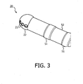
- FIG. 3 shows a perspective view of a catheter 20 suitable for use as an interventional device according to an embodiment of the present invention.
- the tip 22 of the catheter is mounted on a flexible tube 52 for easy manipulation through the human body. Additional ring shaped electrodes 51 on the tube can measure properties like resistance and temperature.
- the tube 52 will contain the needed wires for addressing the transducers and will supply the irrigation liquid.
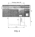
- FIG. 4 shows experimental data from an open-chest sheep model. Radio frequency energy was delivered epicardially to create lesions that were simultaneously monitored with ultrasound and electrical impedance change. Tissue pops were deliberately induced and US data was compared with impedance data. The presence of pops was independently signaled by the physician that performed the ablation and who had no access to the US or impedance data. In clinical practice, loud pops are audible even through the chest of the patient, such as the chest of a sheep.
- the figure shows the data obtained with a set of ultrasound measurements and corresponding impedance measurements of an epicardial ablation with an integrated ring catheter. The ultrasound measurements re visualized in a so-called M-mode image M.
- the graph G depicted shows a temporal development of the electrical impedance during the ablation process.
- the time t is shown on the bottom axis, and the graph G and the M-mode image M share this time axis.
- the RF energy dissipated per time interval is 9 watt during the 20 second period denoted by t a.
- the tissue depth in the M-mode image M is denoted by d_t.
- the absolute scale of the M-mode image is indicated by the scale bar denoted by d1, the scale bar corresponds to 1 millimeter.
- the vertical axis R in the graph G corresponds to electrical impedance measured in Ohm.
- the solid line denoted p_i indicates the incidence of a tissue pop
- the dashed line denoted d_o indicate the onset of changes in ultrasound that precede the pops.
- the figure shows that changes in the ultrasound measurements before tissue pops preceded changes in impedance by several seconds. From the ultrasound M-mode image recorded during the ablation procedure, the change of ultrasound signal could be associated with bubble formation, before the physician signaled the pop.
- FIG. 5 shows a schematic drawing of a system according to an embodiment of the invention, comprising an ultrasound transducer 505, an ablation unit 516, a controlling unit (CTRL). Furthermore is shown an associated tissue 540.
- the controlling unit sends and receives respectively a control signal (CoS) and a response signal (ReS) to and from the ultrasound transducer 505, the response signal being indicative of the presence of one or more bubbles within said associated tissue.
- the controlling unit calculates a predictor value, where the predictor value relates to a risk of impending tissue damage due to a rapid release of bubble energy, and sends a primary signal (RS) if the predictor value exceeds a threshold value.
- the primary signal (RS) is sent to the ablation unit 516.
- the primary signal (RS) might thus serve to decrease an ablation power, in order to decrease a risk of impending tissue damage due to a rapid release of bubble energy.
- FIG. 6 shows another schematic drawing of a system according to an embodiment of the invention, similar to the embodiment shown in FIG. 5 , except that the primary signal is sent to another entity than the ablation unit.
- This other entity may be any entity, in particular it may be any entity controlling irrigation flow, a contact force applied between the interventional device and the associated tissue, a position of the ablation unit.
- FIG. 7 is a flow chart of a method for performing ablation. Such a method comprises the steps of:
- the steps S2 and S5 are carried out using the insight, that generally the tissue pop is preceded by a sudden intensity increase from the ultrasound image.
- image analysis based on different features might be applied to one or more images based on the ultrasound measurements in order to identify a relevant intensity increase, including check if a sudden significant gradient exists in the correlation map. This change should be consistent within a certain depth range (therefore different from noises), or monitor the histogram of one or more current lines in an M-mode image (also known as A-lines), check if there is a significant change in the graylevel distribution as compared to the previous A-line(s).
- Various distance metrics can be applied to compare the histograms such as correlation, Chi-Square, Bhattacharyya distance, etc.
- This approach might be varied so as to include that the histogram (distribution) doesn't have to be performed over the whole A-line.
- the A-line can be segmented into small segments and the histograms of these small segments can be checked.
- the mean, variance or higher order moments can be used to check the difference in histograms, or statistical features for texture characterization, such as entropy or texture parameter estimated from autoregressive models. These features can be used as alternatives for detecting the texture change when the tissue pop happens.
- FIG. 8 shows a diagrammatic depiction of a controlling unit (CTRL) according to an embodiment of the invention, wherein the controlling unit (CTRL) sends a control signal (CoS), such as a control signal for controlling an ultrasound transducer (not shown), and receives a response signal (ReS), such as a signal received from an ultrasound transducer, such as a signal representative of the a measured ultrasonic signal incident on the ultrasound transducer.
- the controlling unit (CTRL) also receives an extra signal (XS) which may be any of a number of signals, such as a signal representative of a temperature, a flow of irrigation, or a contact force between the interventional device and a tissue.
- XS extra signal
- the controlling unit (CTRL) in this embodiment uses a first calculating unit (C1) and a second calculating unit (C2), which both receive both the response signal (ReS) and the extra signal (XS) to calculate respectively a predictor value (PV) and a threshold value (TV).
- the first calculating unit (C1) and the second calculating unit (C2) also receive the control signal (CoS).
- a third calculation unit (C3) compares the predictor value (PV) with the threshold value (TV) and may output a primary signal (RS) which may also be output by the controlling unit if the predictor value (PV) exceeds the threshold value (TV).
- the present invention relates to a system (100) for combined ablation and ultrasound imaging of associated tissue (40), which is particularly useful for use in an ablation process.
- the system comprises an interventional device (20) with an ultrasound transducer and an ablation unit.
- the interventional device (20) can be applied for both ablation and imaging of the tissue (40) subject to the ablation.
- a controlling unit (CTRL) is further comprised within the system, and arranged to calculate a predictor value based on one or more signals from the ultrasound transducer, where the predictor value relates to a risk of impending tissue damage due to a rapid release of bubble energy.
- a primary signal is sent if the predictor value exceeds a threshold value, so that proper measures can be taken.
Landscapes
- Health & Medical Sciences (AREA)
- Surgery (AREA)
- Life Sciences & Earth Sciences (AREA)
- Engineering & Computer Science (AREA)
- Medical Informatics (AREA)
- Molecular Biology (AREA)
- Nuclear Medicine, Radiotherapy & Molecular Imaging (AREA)
- Veterinary Medicine (AREA)
- Biomedical Technology (AREA)
- Heart & Thoracic Surgery (AREA)
- Physics & Mathematics (AREA)
- Otolaryngology (AREA)
- Animal Behavior & Ethology (AREA)
- General Health & Medical Sciences (AREA)
- Public Health (AREA)
- Plasma & Fusion (AREA)
- Electromagnetism (AREA)
- Cardiology (AREA)
- Surgical Instruments (AREA)
- Ultra Sonic Daignosis Equipment (AREA)
Claims (11)
- System (100) zur kombinierten Ablation und Ultraschallbildgebung von zugehörigem Gewebe (40, 540), wobei das System Folgendes umfasst:eine interventionelle Vorrichtung (20), umfassend
einen Ultraschallwandler (5, 505) und eine Ablationseinheit (15, 516), undeine Steuereinheit (CTRL), die funktionsfähig mit der interventionellen Vorrichtung (20) verbunden ist, wobei die Steuereinheit (CTRL) dafür vorgesehen ist,
ein Steuersignal (CoS) an den Ultraschallwandler (5, 505) zu senden,
ein Antwortsignal (ReS) von dem Ultraschallwandler zu empfangen, wobei das Antwortsignal (ReS) auf die Anwesenheit von einer oder mehreren Blasen innerhalb des genannten zugehörigen Gewebes (40, 540) hinweist, und
einen Vorhersagewert (PV) zu berechnen, der sich auf ein Risiko einer bevorstehenden Gewebeschädigung aufgrund einer schnellen Freisetzung einer Blasenenergie bezieht, wobei der Ultraschallwandler (5, 505) dafür vorgesehen ist, Ultraschallsignale (A2) mit einer Frequenz zu emittieren, die ausreichend hoch ist, um eine oder mehrere Blasen in dem zugehörigen Gewebe (40, 540) zu erkennen, und wobei die Frequenz über 10 MHz liegt. - System (100) zur kombinierten Ablation und Ultraschallbildgebung von zugehörigem Gewebe nach Anspruch 1, wobei die Steuereinheit (CTRL) weiterhin dafür vorgesehen ist,
ein Primärsignal (RS) zu senden, wenn der Vorhersagewert einen Schwellenwert (TV) überschreitet. - System (100) zur kombinierten Ablation und Ultraschallbildgebung von zugehörigem Gewebe nach Anspruch 2, wobei das Primärsignal (RS) dafür vorgesehen ist, einen auf die Ablation bezogenen Parameter zu regeln.
- System (100) zur kombinierten Ablation und Ultraschallbildgebung von zugehörigem Gewebe nach Anspruch 1, wobei die Ablationseinheit weiterhin eine Elektrodenspitze mit einer Ablationselektrode und Irrigationsfluss umfasst, wobei der Schwellenwert (TV) eine Funktion von einem der folgenden Elemente ist: einer in dem zugehörigen Gewebe (40, 540) absorbierten Leistung, der Vorgeschichte des Antwortsignals, einer gemessenen Kontaktkraft zwischen der interventionellen Vorrichtung und dem zugehörigen Gewebe (40, 540), einer elektrischen Impedanz des zugehörigen Gewebes (40, 540), einer Struktur des zugehörigen Gewebes (40, 540), einer Dauer der Ablation, der Fähigkeit des zugehörigen Gewebes zum Austauschen von Wärme mit der Umgebung, einer Temperatur des zugehörigen Gewebes (40, 540), der Temperatur der Ablationselektrode oder der Irrigationsflussrate an der Elektrodenspitze.
- System (100) zur kombinierten Ablation und Ultraschallbildgebung von zugehörigem Gewebe (40, 540) nach Anspruch 2, wobei die Steuereinheit (CTRL) dafür vorgesehen ist, das Primärsignal (RS) in Abhängigkeit von dem Wert des Vorhersagewerts (PV) zu variieren.
- System (100) zur kombinierten Ablation und Ultraschallbildgebung von zugehörigem Gewebe (40, 540) nach Anspruch 2, wobei die Steuereinheit (CTRL) dafür vorgesehen ist, einen Teil einer Rückkopplungsschaltung zu bilden.
- System (100) zur kombinierten Ablation und Ultraschallbildgebung von zugehörigem Gewebe (40, 540) nach Anspruch 1, wobei der Ultraschallwandler (5, 505) hinter oder in einem Irrigationsloch (21) der interventionellen Vorrichtung (20) angeordnet ist, so dass eine Irrigationsflüssigkeit aus dem Irrigationsloch (21) herausfließen kann und so dass ein Ultraschallsignal (A2) durch das Irrigationsloch (21) gesendet und/oder empfangen werden kann.
- System (100) zur kombinierten Ablation und Ultraschallbildgebung von zugehörigem Gewebe (40, 540) nach Anspruch 1, wobei die Ablationseinheit (15, 516) eines der folgenden Elemente umfasst: ein Heizelement, eine Hochfrequenzelektrode, einen Ultraschallwandler oder einen Laser.
- System (100) zur kombinierten Ablation und Ultraschallbildgebung von zugehörigem Gewebe (40, 540) nach Anspruch 1, wobei das System eines der folgenden Elemente umfasst: eine Elektrode, die in der Lage ist, als eine Elektrode zum Messen der elektrischen Impedanz des zugehörigen Gewebes (40, 540) zu dienen, einen Kraftsensor, der in der Lage ist, eine zwischen der interventionellen Vorrichtung und dem zugehörigen Gewebe (40, 540) ausgeübte Kontaktkraft zu messen, einen Temperatursensor oder einen Lokalisierungssensor.
- System (100) zur kombinierten Ablation und Ultraschallbildgebung von zugehörigem Gewebe (40, 540) nach Anspruch 2, wobei das Primärsignal (RS) eines der folgenden Elemente steuert: die Ablationseinheit (15, 516), einen Irrigationsfluss, eine zwischen der interventionellen Vorrichtung und dem zugehörigen Gewebe (40, 540) ausgeübte Kontaktkraft oder eine Position der Ablationseinheit.
- Computerprogrammprodukt, das dafür ausgelegt ist, die Steuereinheit des Systems nach einem der vorhergehenden Ansprüche zu betreiben,
um von dem Antwortsignal abgeleitete Informationen zu empfangen, die auf die Anwesenheit von einer oder mehreren Blasen innerhalb des Gewebes hinweisen, wobei die Frequenz des durch den Ultraschallwandler emittierten Ultraschallsignals über 10 MHz liegt, und
um einen Vorhersagewert (PV) basierend auf von dem Antwortsignal abgeleiteten Informationen zu berechnen, wobei sich der Vorhersagewert auf ein Risiko einer bevorstehenden Gewebeschädigung aufgrund einer schnellen Freisetzung eine Blasenenergie bezieht.
Priority Applications (1)
| Application Number | Priority Date | Filing Date | Title |
|---|---|---|---|
| EP11708323.8A EP2531133B1 (de) | 2010-02-05 | 2011-02-03 | Kombinierte ablation und ultraschallbildgebung |
Applications Claiming Priority (3)
| Application Number | Priority Date | Filing Date | Title |
|---|---|---|---|
| EP10152815 | 2010-02-05 | ||
| EP11708323.8A EP2531133B1 (de) | 2010-02-05 | 2011-02-03 | Kombinierte ablation und ultraschallbildgebung |
| PCT/IB2011/050462 WO2011095937A1 (en) | 2010-02-05 | 2011-02-03 | Combined ablation and ultrasound imaging |
Publications (2)
| Publication Number | Publication Date |
|---|---|
| EP2531133A1 EP2531133A1 (de) | 2012-12-12 |
| EP2531133B1 true EP2531133B1 (de) | 2015-04-08 |
Family
ID=44170498
Family Applications (1)
| Application Number | Title | Priority Date | Filing Date |
|---|---|---|---|
| EP11708323.8A Not-in-force EP2531133B1 (de) | 2010-02-05 | 2011-02-03 | Kombinierte ablation und ultraschallbildgebung |
Country Status (7)
| Country | Link |
|---|---|
| US (1) | US10383687B2 (de) |
| EP (1) | EP2531133B1 (de) |
| JP (1) | JP6472940B2 (de) |
| CN (1) | CN102781358B (de) |
| BR (1) | BR112012019262A2 (de) |
| RU (1) | RU2576440C2 (de) |
| WO (1) | WO2011095937A1 (de) |
Families Citing this family (50)
| Publication number | Priority date | Publication date | Assignee | Title |
|---|---|---|---|---|
| US9795442B2 (en) | 2008-11-11 | 2017-10-24 | Shifamed Holdings, Llc | Ablation catheters |
| WO2010093603A1 (en) | 2009-02-11 | 2010-08-19 | Boston Scientific Scimed, Inc. | Insulated ablation catheter devices and methods of use |
| US9277961B2 (en) | 2009-06-12 | 2016-03-08 | Advanced Cardiac Therapeutics, Inc. | Systems and methods of radiometrically determining a hot-spot temperature of tissue being treated |
| US8954161B2 (en) | 2012-06-01 | 2015-02-10 | Advanced Cardiac Therapeutics, Inc. | Systems and methods for radiometrically measuring temperature and detecting tissue contact prior to and during tissue ablation |
| US9226791B2 (en) | 2012-03-12 | 2016-01-05 | Advanced Cardiac Therapeutics, Inc. | Systems for temperature-controlled ablation using radiometric feedback |
| US8926605B2 (en) | 2012-02-07 | 2015-01-06 | Advanced Cardiac Therapeutics, Inc. | Systems and methods for radiometrically measuring temperature during tissue ablation |
| JP5490235B2 (ja) | 2009-06-30 | 2014-05-14 | ボストン サイエンティフィック サイムド,インコーポレイテッド | マップ及び切除のための開放洗浄ハイブリッドカテーテル |
| CA2797130A1 (en) | 2010-05-12 | 2011-11-17 | Shifamed Holdings, Llc | Low profile electrode assembly |
| US9655677B2 (en) | 2010-05-12 | 2017-05-23 | Shifamed Holdings, Llc | Ablation catheters including a balloon and electrodes |
| US9089340B2 (en) | 2010-12-30 | 2015-07-28 | Boston Scientific Scimed, Inc. | Ultrasound guided tissue ablation |
| JP2014516723A (ja) | 2011-06-01 | 2014-07-17 | ボストン サイエンティフィック サイムド,インコーポレイテッド | 超音波映像性能を備えた切除プローブ |
| EP2755587B1 (de) | 2011-09-14 | 2018-11-21 | Boston Scientific Scimed, Inc. | Ablationsvorrichtung mit mehreren ablationsmodi |
| CA2848053A1 (en) | 2011-09-14 | 2013-03-21 | Boston Scientific Scimed, Inc. | Ablation device with ionically conductive balloon |
| WO2013102072A1 (en) | 2011-12-28 | 2013-07-04 | Boston Scientific Scimed, Inc. | Ablation probe with ultrasonic imaging capability |
| CA2860636A1 (en) | 2012-01-10 | 2013-07-18 | Boston Scientific Scimed, Inc. | Electrophysiology system |
| JP5830614B2 (ja) | 2012-01-31 | 2015-12-09 | ボストン サイエンティフィック サイムド,インコーポレイテッドBoston Scientific Scimed,Inc. | 超音波組織撮像のための流体に基づいた音響結合を有するアブレーションプローブ、および、アブレーションおよび超音波撮像システム |
| WO2014005155A1 (en) | 2012-06-30 | 2014-01-03 | Cibiem, Inc. | Carotid body ablation via directed energy |
| US9955946B2 (en) | 2014-03-12 | 2018-05-01 | Cibiem, Inc. | Carotid body ablation with a transvenous ultrasound imaging and ablation catheter |
| EP2945558B1 (de) | 2013-03-15 | 2018-01-31 | St. Jude Medical Atrial Fibrillation Division Inc. | Ablationskatheter mit krafterfassung |
| WO2014168987A1 (en) | 2013-04-08 | 2014-10-16 | Shifamed Holdings, Llc | Cardiac ablation catheters and methods of use thereof |
| US10098694B2 (en) | 2013-04-08 | 2018-10-16 | Apama Medical, Inc. | Tissue ablation and monitoring thereof |
| US10349824B2 (en) | 2013-04-08 | 2019-07-16 | Apama Medical, Inc. | Tissue mapping and visualization systems |
| US10945660B2 (en) | 2014-03-27 | 2021-03-16 | Koninklijke Philips N.V. | Normalized-displacement-difference-based approach for thermal lesion size control |
| US10524684B2 (en) | 2014-10-13 | 2020-01-07 | Boston Scientific Scimed Inc | Tissue diagnosis and treatment using mini-electrodes |
| WO2016065337A1 (en) | 2014-10-24 | 2016-04-28 | Boston Scientific Scimed Inc. | Medical devices with a flexible electrode assembly coupled to an ablation tip |
| JP6673598B2 (ja) | 2014-11-19 | 2020-03-25 | エピックス セラピューティクス,インコーポレイテッド | ペーシングを伴う組織の高分解能マッピング |
| KR20170107428A (ko) | 2014-11-19 | 2017-09-25 | 어드밴스드 카디악 테라퓨틱스, 인크. | 고분해능 전극 어셈블리를 이용한 절제 장치, 시스템 및 방법 |
| WO2016081606A1 (en) | 2014-11-19 | 2016-05-26 | Advanced Cardiac Therapeutics, Inc. | Systems and methods for high-resolution mapping of tissue |
| CN106999080B (zh) | 2014-12-18 | 2020-08-18 | 波士顿科学医学有限公司 | 针对病变评估的实时形态分析 |
| EP3258870A1 (de) * | 2015-02-17 | 2017-12-27 | Koninklijke Philips N.V. | Vorrichtung und verfahren zur unterstützung von gewebeablation |
| US9636164B2 (en) | 2015-03-25 | 2017-05-02 | Advanced Cardiac Therapeutics, Inc. | Contact sensing systems and methods |
| EP4302713A3 (de) | 2015-11-16 | 2024-03-13 | Boston Scientific Scimed, Inc. | Energieabgabevorrichtungen |
| US11160607B2 (en) | 2015-11-20 | 2021-11-02 | Biosense Webster (Israel) Ltd. | Hyper-apertured ablation electrode |
| JP6923549B2 (ja) | 2016-03-15 | 2021-08-18 | エピックス セラピューティクス,インコーポレイテッド | 灌注式焼灼のための改良されたシステム |
| JP7003061B2 (ja) | 2016-05-02 | 2022-01-20 | アフェラ, インコーポレイテッド | カテーテル感知および潅注 |
| RU2654764C2 (ru) * | 2016-08-17 | 2018-05-22 | Федеральное государственное бюджетное образовательное учреждение высшего образования "Саратовский национальный исследовательский государственный университет имени Н.Г. Чернышевского" | Способ лазерной абляции патологической области сердца |
| US20180235576A1 (en) * | 2017-02-22 | 2018-08-23 | Covidien Lp | Ultrasound doppler and elastography for ablation prediction and monitoring |
| EP3614946B1 (de) | 2017-04-27 | 2024-03-20 | EPiX Therapeutics, Inc. | Bestimmung der art des kontaktes zwischen katheterspitze und gewebe |
| US11819360B2 (en) * | 2017-08-15 | 2023-11-21 | Koninklijke Philips N.V. | Intraluminal rotational ultrasound for diagnostic imaging and therapy |
| US10828020B2 (en) | 2018-08-22 | 2020-11-10 | Covidien Lp | Surgical retractor including three-dimensional (3D) imaging capability |
| US11298106B2 (en) | 2018-08-31 | 2022-04-12 | Covidien Lp | Minimally-invasive surgical instrument including three-dimensional (3D) ultrasound imaging and focused ultrasound treatment capabilities |
| CN110755148B (zh) * | 2019-09-20 | 2020-09-08 | 姚陈果 | 脉冲电场肿瘤消融参数优化系统 |
| JP7636417B2 (ja) | 2019-12-16 | 2025-02-26 | アフェラ, インコーポレイテッド | 肺静脈絶縁カテーテルおよび関連付けられるデバイス、システム、ならびに方法 |
| WO2022002653A1 (en) * | 2020-06-30 | 2022-01-06 | Koninklijke Philips N.V. | Systems for laser catheter treatment in a vessel lumen |
| US11051883B1 (en) * | 2020-11-18 | 2021-07-06 | Endra Life Sciences Inc. | Thermal ablation system and method with integrated thermoacoustic temperature measurement |
| USD1014762S1 (en) | 2021-06-16 | 2024-02-13 | Affera, Inc. | Catheter tip with electrode panel(s) |
| WO2023039394A1 (en) * | 2021-09-08 | 2023-03-16 | Lastarria Emilio | Laser ablation surgery system with safety control of temperature and pressure at surgical site and method of use |
| CN114176759A (zh) * | 2021-12-09 | 2022-03-15 | 上海阿法钛医疗器械有限公司 | 一种消融成像导管 |
| CN114587565B (zh) * | 2022-03-01 | 2023-09-29 | 河南中医药大学 | 一种射频消融中温度控制方法及系统 |
| CN117883723A (zh) * | 2024-01-05 | 2024-04-16 | 上海魅丽纬叶医疗科技有限公司 | 一种超声消融设备及系统 |
Family Cites Families (15)
| Publication number | Priority date | Publication date | Assignee | Title |
|---|---|---|---|---|
| GB9106686D0 (en) | 1991-03-28 | 1991-05-15 | Hafslund Nycomed As | Improvements in or relating to contrast agents |
| US5246436A (en) * | 1991-12-18 | 1993-09-21 | Alcon Surgical, Inc. | Midinfrared laser tissue ablater |
| US20080154257A1 (en) | 2006-12-22 | 2008-06-26 | Shiva Sharareh | Real-time optoacoustic monitoring with electophysiologic catheters |
| NZ522128A (en) * | 2000-03-31 | 2003-08-29 | Rita Medical Systems Inc | Tissue biopsy and treatment apparatus and method |
| RU2232547C2 (ru) * | 2002-03-29 | 2004-07-20 | Общество с ограниченной ответственностью "АММ - 2000" | Способ и устройство для получения ультразвуковых изображений структур и сосудов головного мозга |
| US6709432B2 (en) | 2002-04-26 | 2004-03-23 | Medtronic, Inc. | Ablation methods and medical apparatus using same |
| US20050154314A1 (en) | 2003-12-30 | 2005-07-14 | Liposonix, Inc. | Component ultrasound transducer |
| US20050283074A1 (en) | 2004-06-22 | 2005-12-22 | Siemens Medical Solutions Usa, Inc. | Ultrasound feedback for tissue ablation procedures |
| US7918850B2 (en) | 2006-02-17 | 2011-04-05 | Biosense Wabster, Inc. | Lesion assessment by pacing |
| EP3756604A1 (de) * | 2006-05-12 | 2020-12-30 | Vytronus, Inc. | Vorrichtung zur abaltion von körpergewebe |
| WO2008017992A2 (en) | 2006-08-11 | 2008-02-14 | Koninklijke Philips Electronics, N.V. | Systems and methods for associating nucleic acid profiles and proteomic profiles with healthcare protocols and guidelines in a decision support system |
| CN101500502B (zh) * | 2006-08-11 | 2013-01-02 | 皇家飞利浦电子股份有限公司 | 用于对射频组织消融进行最佳超声成像的基于图像的功率反馈 |
| EP2155036B1 (de) * | 2007-05-11 | 2016-02-24 | Intuitive Surgical Operations, Inc. | Visuelle elektrodenablationssysteme |
| US20090287205A1 (en) | 2008-05-16 | 2009-11-19 | Boston Scientific Scimed, Inc. | Systems and methods for preventing tissue popping caused by bubble expansion during tissue ablation |
| US8414508B2 (en) * | 2008-10-30 | 2013-04-09 | Vytronus, Inc. | System and method for delivery of energy to tissue while compensating for collateral tissue |
-
2011
- 2011-02-03 EP EP11708323.8A patent/EP2531133B1/de not_active Not-in-force
- 2011-02-03 WO PCT/IB2011/050462 patent/WO2011095937A1/en not_active Ceased
- 2011-02-03 RU RU2012137787/14A patent/RU2576440C2/ru not_active IP Right Cessation
- 2011-02-03 US US13/576,022 patent/US10383687B2/en not_active Expired - Fee Related
- 2011-02-03 JP JP2012551723A patent/JP6472940B2/ja not_active Expired - Fee Related
- 2011-02-03 BR BR112012019262-0A patent/BR112012019262A2/pt not_active IP Right Cessation
- 2011-02-03 CN CN201180008102.2A patent/CN102781358B/zh not_active Expired - Fee Related
Also Published As
| Publication number | Publication date |
|---|---|
| US10383687B2 (en) | 2019-08-20 |
| CN102781358A (zh) | 2012-11-14 |
| JP2013518659A (ja) | 2013-05-23 |
| RU2012137787A (ru) | 2014-03-10 |
| EP2531133A1 (de) | 2012-12-12 |
| BR112012019262A2 (pt) | 2021-03-09 |
| WO2011095937A1 (en) | 2011-08-11 |
| JP6472940B2 (ja) | 2019-02-20 |
| CN102781358B (zh) | 2015-06-24 |
| US20120302877A1 (en) | 2012-11-29 |
| RU2576440C2 (ru) | 2016-03-10 |
Similar Documents
| Publication | Publication Date | Title |
|---|---|---|
| EP2531133B1 (de) | Kombinierte ablation und ultraschallbildgebung | |
| JP5976782B2 (ja) | 音響フィードバックを用いるrfアブレーションシステム用の装置及びインタフェース | |
| CN102421356B (zh) | 用于确定心脏的性质的装置、方法以及计算机程序 | |
| JP5855739B2 (ja) | アブレーションカテーテルにおいて焼灼巣フィードバックのために角度方向付けを用いる単一トランスデューサ | |
| CN103220983B (zh) | 用于感测对象的感测装置 | |
| US9033885B2 (en) | System and method for energy delivery to tissue while monitoring position, lesion depth, and wall motion | |
| RU2572748C2 (ru) | Энергоподающее устройство для подачи энергии к объекту | |
| CN102481170B (zh) | 用于组织的开环冲洗消融的导管 | |
| US11497464B2 (en) | Medical ultrasound device with temperature detection at distal end | |
| CN102858252B (zh) | 用于确定对象的性质的性质确定装置 | |
| US20160074679A1 (en) | System and method for energy delivery to tissue while monitoring position, lesion depth, and wall motion | |
| CN109589168B (zh) | 冷冻球囊导管和冷冻消融系统 | |
| EP1643912B1 (de) | Kombination von Therapieinstrument und Bildgebendem Instrument | |
| EP3074090A1 (de) | Vorrichtung zur ablation und fotoakustischen bildgebung | |
| US11298568B2 (en) | System and method for energy delivery to tissue while monitoring position, lesion depth, and wall motion | |
| EP3226773B1 (de) | Systeme für verletzungsbildungsfeedback |
Legal Events
| Date | Code | Title | Description |
|---|---|---|---|
| PUAI | Public reference made under article 153(3) epc to a published international application that has entered the european phase |
Free format text: ORIGINAL CODE: 0009012 |
|
| 17P | Request for examination filed |
Effective date: 20120905 |
|
| AK | Designated contracting states |
Kind code of ref document: A1 Designated state(s): AL AT BE BG CH CY CZ DE DK EE ES FI FR GB GR HR HU IE IS IT LI LT LU LV MC MK MT NL NO PL PT RO RS SE SI SK SM TR |
|
| DAX | Request for extension of the european patent (deleted) | ||
| RAP1 | Party data changed (applicant data changed or rights of an application transferred) |
Owner name: KONINKLIJKE PHILIPS N.V. |
|
| GRAP | Despatch of communication of intention to grant a patent |
Free format text: ORIGINAL CODE: EPIDOSNIGR1 |
|
| INTG | Intention to grant announced |
Effective date: 20140903 |
|
| GRAS | Grant fee paid |
Free format text: ORIGINAL CODE: EPIDOSNIGR3 |
|
| GRAA | (expected) grant |
Free format text: ORIGINAL CODE: 0009210 |
|
| AK | Designated contracting states |
Kind code of ref document: B1 Designated state(s): AL AT BE BG CH CY CZ DE DK EE ES FI FR GB GR HR HU IE IS IT LI LT LU LV MC MK MT NL NO PL PT RO RS SE SI SK SM TR |
|
| REG | Reference to a national code |
Ref country code: GB Ref legal event code: FG4D |
|
| REG | Reference to a national code |
Ref country code: CH Ref legal event code: EP |
|
| REG | Reference to a national code |
Ref country code: IE Ref legal event code: FG4D |
|
| REG | Reference to a national code |
Ref country code: AT Ref legal event code: REF Ref document number: 719905 Country of ref document: AT Kind code of ref document: T Effective date: 20150515 |
|
| REG | Reference to a national code |
Ref country code: DE Ref legal event code: R096 Ref document number: 602011015444 Country of ref document: DE Effective date: 20150521 |
|
| REG | Reference to a national code |
Ref country code: AT Ref legal event code: MK05 Ref document number: 719905 Country of ref document: AT Kind code of ref document: T Effective date: 20150408 |
|
| REG | Reference to a national code |
Ref country code: NL Ref legal event code: VDEP Effective date: 20150408 |
|
| REG | Reference to a national code |
Ref country code: LT Ref legal event code: MG4D |
|
| PG25 | Lapsed in a contracting state [announced via postgrant information from national office to epo] |
Ref country code: NL Free format text: LAPSE BECAUSE OF FAILURE TO SUBMIT A TRANSLATION OF THE DESCRIPTION OR TO PAY THE FEE WITHIN THE PRESCRIBED TIME-LIMIT Effective date: 20150408 |
|
| PG25 | Lapsed in a contracting state [announced via postgrant information from national office to epo] |
Ref country code: FI Free format text: LAPSE BECAUSE OF FAILURE TO SUBMIT A TRANSLATION OF THE DESCRIPTION OR TO PAY THE FEE WITHIN THE PRESCRIBED TIME-LIMIT Effective date: 20150408 Ref country code: LT Free format text: LAPSE BECAUSE OF FAILURE TO SUBMIT A TRANSLATION OF THE DESCRIPTION OR TO PAY THE FEE WITHIN THE PRESCRIBED TIME-LIMIT Effective date: 20150408 Ref country code: HR Free format text: LAPSE BECAUSE OF FAILURE TO SUBMIT A TRANSLATION OF THE DESCRIPTION OR TO PAY THE FEE WITHIN THE PRESCRIBED TIME-LIMIT Effective date: 20150408 Ref country code: PT Free format text: LAPSE BECAUSE OF FAILURE TO SUBMIT A TRANSLATION OF THE DESCRIPTION OR TO PAY THE FEE WITHIN THE PRESCRIBED TIME-LIMIT Effective date: 20150810 Ref country code: NO Free format text: LAPSE BECAUSE OF FAILURE TO SUBMIT A TRANSLATION OF THE DESCRIPTION OR TO PAY THE FEE WITHIN THE PRESCRIBED TIME-LIMIT Effective date: 20150708 Ref country code: ES Free format text: LAPSE BECAUSE OF FAILURE TO SUBMIT A TRANSLATION OF THE DESCRIPTION OR TO PAY THE FEE WITHIN THE PRESCRIBED TIME-LIMIT Effective date: 20150408 |
|
| PG25 | Lapsed in a contracting state [announced via postgrant information from national office to epo] |
Ref country code: GR Free format text: LAPSE BECAUSE OF FAILURE TO SUBMIT A TRANSLATION OF THE DESCRIPTION OR TO PAY THE FEE WITHIN THE PRESCRIBED TIME-LIMIT Effective date: 20150709 Ref country code: AT Free format text: LAPSE BECAUSE OF FAILURE TO SUBMIT A TRANSLATION OF THE DESCRIPTION OR TO PAY THE FEE WITHIN THE PRESCRIBED TIME-LIMIT Effective date: 20150408 Ref country code: IS Free format text: LAPSE BECAUSE OF FAILURE TO SUBMIT A TRANSLATION OF THE DESCRIPTION OR TO PAY THE FEE WITHIN THE PRESCRIBED TIME-LIMIT Effective date: 20150808 Ref country code: LV Free format text: LAPSE BECAUSE OF FAILURE TO SUBMIT A TRANSLATION OF THE DESCRIPTION OR TO PAY THE FEE WITHIN THE PRESCRIBED TIME-LIMIT Effective date: 20150408 Ref country code: RS Free format text: LAPSE BECAUSE OF FAILURE TO SUBMIT A TRANSLATION OF THE DESCRIPTION OR TO PAY THE FEE WITHIN THE PRESCRIBED TIME-LIMIT Effective date: 20150408 |
|
| REG | Reference to a national code |
Ref country code: DE Ref legal event code: R097 Ref document number: 602011015444 Country of ref document: DE |
|
| PG25 | Lapsed in a contracting state [announced via postgrant information from national office to epo] |
Ref country code: EE Free format text: LAPSE BECAUSE OF FAILURE TO SUBMIT A TRANSLATION OF THE DESCRIPTION OR TO PAY THE FEE WITHIN THE PRESCRIBED TIME-LIMIT Effective date: 20150408 Ref country code: DK Free format text: LAPSE BECAUSE OF FAILURE TO SUBMIT A TRANSLATION OF THE DESCRIPTION OR TO PAY THE FEE WITHIN THE PRESCRIBED TIME-LIMIT Effective date: 20150408 |
|
| PLBE | No opposition filed within time limit |
Free format text: ORIGINAL CODE: 0009261 |
|
| STAA | Information on the status of an ep patent application or granted ep patent |
Free format text: STATUS: NO OPPOSITION FILED WITHIN TIME LIMIT |
|
| PG25 | Lapsed in a contracting state [announced via postgrant information from national office to epo] |
Ref country code: CZ Free format text: LAPSE BECAUSE OF FAILURE TO SUBMIT A TRANSLATION OF THE DESCRIPTION OR TO PAY THE FEE WITHIN THE PRESCRIBED TIME-LIMIT Effective date: 20150408 Ref country code: RO Free format text: LAPSE BECAUSE OF NON-PAYMENT OF DUE FEES Effective date: 20150408 Ref country code: PL Free format text: LAPSE BECAUSE OF FAILURE TO SUBMIT A TRANSLATION OF THE DESCRIPTION OR TO PAY THE FEE WITHIN THE PRESCRIBED TIME-LIMIT Effective date: 20150408 Ref country code: SK Free format text: LAPSE BECAUSE OF FAILURE TO SUBMIT A TRANSLATION OF THE DESCRIPTION OR TO PAY THE FEE WITHIN THE PRESCRIBED TIME-LIMIT Effective date: 20150408 |
|
| REG | Reference to a national code |
Ref country code: FR Ref legal event code: PLFP Year of fee payment: 6 |
|
| 26N | No opposition filed |
Effective date: 20160111 |
|
| PG25 | Lapsed in a contracting state [announced via postgrant information from national office to epo] |
Ref country code: IT Free format text: LAPSE BECAUSE OF FAILURE TO SUBMIT A TRANSLATION OF THE DESCRIPTION OR TO PAY THE FEE WITHIN THE PRESCRIBED TIME-LIMIT Effective date: 20150408 |
|
| PG25 | Lapsed in a contracting state [announced via postgrant information from national office to epo] |
Ref country code: SI Free format text: LAPSE BECAUSE OF FAILURE TO SUBMIT A TRANSLATION OF THE DESCRIPTION OR TO PAY THE FEE WITHIN THE PRESCRIBED TIME-LIMIT Effective date: 20150408 Ref country code: BE Free format text: LAPSE BECAUSE OF NON-PAYMENT OF DUE FEES Effective date: 20160229 |
|
| PG25 | Lapsed in a contracting state [announced via postgrant information from national office to epo] |
Ref country code: BE Free format text: LAPSE BECAUSE OF FAILURE TO SUBMIT A TRANSLATION OF THE DESCRIPTION OR TO PAY THE FEE WITHIN THE PRESCRIBED TIME-LIMIT Effective date: 20150408 |
|
| PG25 | Lapsed in a contracting state [announced via postgrant information from national office to epo] |
Ref country code: LU Free format text: LAPSE BECAUSE OF FAILURE TO SUBMIT A TRANSLATION OF THE DESCRIPTION OR TO PAY THE FEE WITHIN THE PRESCRIBED TIME-LIMIT Effective date: 20160203 Ref country code: MC Free format text: LAPSE BECAUSE OF FAILURE TO SUBMIT A TRANSLATION OF THE DESCRIPTION OR TO PAY THE FEE WITHIN THE PRESCRIBED TIME-LIMIT Effective date: 20150408 |
|
| REG | Reference to a national code |
Ref country code: CH Ref legal event code: PL |
|
| PG25 | Lapsed in a contracting state [announced via postgrant information from national office to epo] |
Ref country code: CH Free format text: LAPSE BECAUSE OF NON-PAYMENT OF DUE FEES Effective date: 20160229 Ref country code: LI Free format text: LAPSE BECAUSE OF NON-PAYMENT OF DUE FEES Effective date: 20160229 |
|
| REG | Reference to a national code |
Ref country code: IE Ref legal event code: MM4A |
|
| PG25 | Lapsed in a contracting state [announced via postgrant information from national office to epo] |
Ref country code: IE Free format text: LAPSE BECAUSE OF NON-PAYMENT OF DUE FEES Effective date: 20160203 |
|
| REG | Reference to a national code |
Ref country code: FR Ref legal event code: PLFP Year of fee payment: 7 |
|
| PG25 | Lapsed in a contracting state [announced via postgrant information from national office to epo] |
Ref country code: SE Free format text: LAPSE BECAUSE OF FAILURE TO SUBMIT A TRANSLATION OF THE DESCRIPTION OR TO PAY THE FEE WITHIN THE PRESCRIBED TIME-LIMIT Effective date: 20150408 |
|
| PG25 | Lapsed in a contracting state [announced via postgrant information from national office to epo] |
Ref country code: MT Free format text: LAPSE BECAUSE OF FAILURE TO SUBMIT A TRANSLATION OF THE DESCRIPTION OR TO PAY THE FEE WITHIN THE PRESCRIBED TIME-LIMIT Effective date: 20150408 |
|
| REG | Reference to a national code |
Ref country code: FR Ref legal event code: PLFP Year of fee payment: 8 |
|
| PG25 | Lapsed in a contracting state [announced via postgrant information from national office to epo] |
Ref country code: SM Free format text: LAPSE BECAUSE OF FAILURE TO SUBMIT A TRANSLATION OF THE DESCRIPTION OR TO PAY THE FEE WITHIN THE PRESCRIBED TIME-LIMIT Effective date: 20150408 Ref country code: HU Free format text: LAPSE BECAUSE OF FAILURE TO SUBMIT A TRANSLATION OF THE DESCRIPTION OR TO PAY THE FEE WITHIN THE PRESCRIBED TIME-LIMIT; INVALID AB INITIO Effective date: 20110203 Ref country code: CY Free format text: LAPSE BECAUSE OF FAILURE TO SUBMIT A TRANSLATION OF THE DESCRIPTION OR TO PAY THE FEE WITHIN THE PRESCRIBED TIME-LIMIT Effective date: 20150408 |
|
| PG25 | Lapsed in a contracting state [announced via postgrant information from national office to epo] |
Ref country code: MK Free format text: LAPSE BECAUSE OF FAILURE TO SUBMIT A TRANSLATION OF THE DESCRIPTION OR TO PAY THE FEE WITHIN THE PRESCRIBED TIME-LIMIT Effective date: 20150408 Ref country code: TR Free format text: LAPSE BECAUSE OF FAILURE TO SUBMIT A TRANSLATION OF THE DESCRIPTION OR TO PAY THE FEE WITHIN THE PRESCRIBED TIME-LIMIT Effective date: 20150408 Ref country code: MT Free format text: LAPSE BECAUSE OF FAILURE TO SUBMIT A TRANSLATION OF THE DESCRIPTION OR TO PAY THE FEE WITHIN THE PRESCRIBED TIME-LIMIT Effective date: 20160229 |
|
| PG25 | Lapsed in a contracting state [announced via postgrant information from national office to epo] |
Ref country code: BG Free format text: LAPSE BECAUSE OF FAILURE TO SUBMIT A TRANSLATION OF THE DESCRIPTION OR TO PAY THE FEE WITHIN THE PRESCRIBED TIME-LIMIT Effective date: 20150408 |
|
| PG25 | Lapsed in a contracting state [announced via postgrant information from national office to epo] |
Ref country code: AL Free format text: LAPSE BECAUSE OF FAILURE TO SUBMIT A TRANSLATION OF THE DESCRIPTION OR TO PAY THE FEE WITHIN THE PRESCRIBED TIME-LIMIT Effective date: 20150408 |
|
| PGFP | Annual fee paid to national office [announced via postgrant information from national office to epo] |
Ref country code: FR Payment date: 20210223 Year of fee payment: 11 |
|
| PGFP | Annual fee paid to national office [announced via postgrant information from national office to epo] |
Ref country code: GB Payment date: 20210223 Year of fee payment: 11 Ref country code: DE Payment date: 20210225 Year of fee payment: 11 |
|
| REG | Reference to a national code |
Ref country code: DE Ref legal event code: R119 Ref document number: 602011015444 Country of ref document: DE |
|
| GBPC | Gb: european patent ceased through non-payment of renewal fee |
Effective date: 20220203 |
|
| PG25 | Lapsed in a contracting state [announced via postgrant information from national office to epo] |
Ref country code: FR Free format text: LAPSE BECAUSE OF NON-PAYMENT OF DUE FEES Effective date: 20220228 |
|
| PG25 | Lapsed in a contracting state [announced via postgrant information from national office to epo] |
Ref country code: GB Free format text: LAPSE BECAUSE OF NON-PAYMENT OF DUE FEES Effective date: 20220203 Ref country code: DE Free format text: LAPSE BECAUSE OF NON-PAYMENT OF DUE FEES Effective date: 20220901 |