EP2530230A2 - Isoliersteg für Fenster- und Türrahmen - Google Patents
Isoliersteg für Fenster- und Türrahmen Download PDFInfo
- Publication number
- EP2530230A2 EP2530230A2 EP12167637A EP12167637A EP2530230A2 EP 2530230 A2 EP2530230 A2 EP 2530230A2 EP 12167637 A EP12167637 A EP 12167637A EP 12167637 A EP12167637 A EP 12167637A EP 2530230 A2 EP2530230 A2 EP 2530230A2
- Authority
- EP
- European Patent Office
- Prior art keywords
- region
- profile
- insulating web
- insulating
- shear
- Prior art date
- Legal status (The legal status is an assumption and is not a legal conclusion. Google has not performed a legal analysis and makes no representation as to the accuracy of the status listed.)
- Granted
Links
Images


Classifications
-
- E—FIXED CONSTRUCTIONS
- E06—DOORS, WINDOWS, SHUTTERS, OR ROLLER BLINDS IN GENERAL; LADDERS
- E06B—FIXED OR MOVABLE CLOSURES FOR OPENINGS IN BUILDINGS, VEHICLES, FENCES OR LIKE ENCLOSURES IN GENERAL, e.g. DOORS, WINDOWS, BLINDS, GATES
- E06B3/00—Window sashes, door leaves, or like elements for closing wall or like openings; Layout of fixed or moving closures, e.g. windows in wall or like openings; Features of rigidly-mounted outer frames relating to the mounting of wing frames
- E06B3/04—Wing frames not characterised by the manner of movement
- E06B3/263—Frames with special provision for insulation
- E06B3/26301—Frames with special provision for insulation with prefabricated insulating strips between two metal section members
- E06B3/26303—Frames with special provision for insulation with prefabricated insulating strips between two metal section members with thin strips, e.g. defining a hollow space between the metal section members
-
- E—FIXED CONSTRUCTIONS
- E06—DOORS, WINDOWS, SHUTTERS, OR ROLLER BLINDS IN GENERAL; LADDERS
- E06B—FIXED OR MOVABLE CLOSURES FOR OPENINGS IN BUILDINGS, VEHICLES, FENCES OR LIKE ENCLOSURES IN GENERAL, e.g. DOORS, WINDOWS, BLINDS, GATES
- E06B3/00—Window sashes, door leaves, or like elements for closing wall or like openings; Layout of fixed or moving closures, e.g. windows in wall or like openings; Features of rigidly-mounted outer frames relating to the mounting of wing frames
- E06B3/04—Wing frames not characterised by the manner of movement
- E06B3/263—Frames with special provision for insulation
- E06B2003/26349—Details of insulating strips
- E06B2003/2635—Specific form characteristics
- E06B2003/26359—Specific form characteristics making flush mounting with neighbouring metal section members possible
-
- E—FIXED CONSTRUCTIONS
- E06—DOORS, WINDOWS, SHUTTERS, OR ROLLER BLINDS IN GENERAL; LADDERS
- E06B—FIXED OR MOVABLE CLOSURES FOR OPENINGS IN BUILDINGS, VEHICLES, FENCES OR LIKE ENCLOSURES IN GENERAL, e.g. DOORS, WINDOWS, BLINDS, GATES
- E06B3/00—Window sashes, door leaves, or like elements for closing wall or like openings; Layout of fixed or moving closures, e.g. windows in wall or like openings; Features of rigidly-mounted outer frames relating to the mounting of wing frames
- E06B3/04—Wing frames not characterised by the manner of movement
- E06B3/263—Frames with special provision for insulation
- E06B2003/26349—Details of insulating strips
- E06B2003/26387—Performing extra functions
Definitions
- the invention relates to an insulating web for window and door frames according to the preamble of independent claim 1.
- the invention particularly relates to an insulating web for mechanically connecting an inside profile with an outside profile. Furthermore, the invention relates to a composite profile, which has an insulating web according to the invention, and a window or door frame, which is made of a composite profile according to the invention.
- shear-resistant connections in the longitudinal direction of the composite profile between the insulating webs and the profile chambers takes on the attack of static or dynamic loads (for example gusts) on the resulting shear forces and thus counteracts a deflection of the composite profile.
- Such mechanical connections are generally referred to as “shear-resistant connections”.
- the outside profile chamber is often exposed to a different temperature than is the case for the inside profile chamber.
- the outside profile chamber for example, in the winter months, exposed to a lower temperature than the inside profile chamber. Accordingly, the formation of this temperature gradient causes the two profile chambers experience a different thermal expansion, whereby a relative movement of the profile chambers arises.
- shear resistant Isolierstegen to a delay of the composite profiles with negative side effects such as leakage and / or malfunction of the door or the window whose frame was made of a shear-resistant composite profile.
- the aforementioned two-piece insulating bars known from the prior art have the problem that unwanted relative movements of the profile chambers to one another (for example due to gusts of wind) can not be prevented.
- the known insulating webs allow a compensation of displacement movements in the longitudinal direction of the composite profile, but they are usually not designed to compensate for relative movements in the horizontal or vertical direction.
- the two-part insulating bars must meet high tolerance requirements to ensure a sufficiently high mechanical connection between the profile chambers of the composite profile after assembly.
- the present invention seeks to provide an insulating web for window and door frames, which is able to compensate for displacements of the composite profile due to thermal expansion in all directions.
- the insulating web according to the invention for window and door frame is characterized in that it is integrally formed and can be brought from a first, shear-resistant state in a second, in the longitudinal direction 29ub Wars state.
- the insulating web according to the invention has the advantage that it is integrally formed and thus can be produced in one step. Consequently, it is not only possible to simplify the manufacturing process of the insulating web, but also a simplification of the mounting of the insulating web according to the invention is achieved on the profiles or profile chambers of the composite profile. Since the Furthermore, it is also possible to use this for window and door frames, which require no Verschubweichheit. In addition, it is conceivable that isolated insulating webs of the composite profile of a window or door frame are left in their shear-resistant state, while other insulating webs have the second, in the longitudinal Verschub Wars state to compensate for expansions due to heat differences. It is therefore possible that the Verschfolweichheit the composite profile can be adjusted individually at any time to adapt the composite profile to the local weather conditions.
- the insulating web has a first region, which is connected in a shear-resistant manner to the inside profile, and a second region, which is connected to the outside profile chamber.
- the insulating bar has a third area, which is formed between the first and the second area and designed to connect the first area perpendicular to the longitudinal direction movably with the second area.
- the insulating web according to the invention according to this embodiment is also designed to allow a Verschfolweichheit, not only in the longitudinal direction of the composite profile. Rather, it is preferably possible that the insulating web can accommodate displacement movements due to thermal expansion in all directions.
- the third region of the insulating web can accordingly be designed such that it forms a joint which movably connects the first and second regions in all three spatial directions. Consequently, it is also possible by the insulating web according to the invention to accommodate displacement movements of the profiles perpendicular to the longitudinal direction of the composite profile.
- the first partial region has a first circumferential groove on a first end region facing away from the inside profile and the second region has a second circular groove on a first end region facing away from the outside profile.
- the third area has a guide arm for guiding the third area within the circular grooves.
- the above-mentioned guide arm has a first guide element for guiding the guide arm along the first circular groove, and a second guide element for guiding the guide arm along the second circular groove.
- these first and second guide elements are adapted in their construction to the circular grooves.
- the guide elements of the third region enable a positive connection with the round grooves of the first or second region.
- the grooves are undercut polygonal grooves, but the round grooves according to the invention ensure a higher mobility of the composite profile.
- the third area is designed to form a cover profile that runs parallel to the first and second area.
- a cover profile can be used to give the insulating web additional stability and consequently to improve the mechanical connection between the inside profile and the outside profile. Furthermore, it is conceivable that such a cover profile further improves the heat insulation between the two profiles.
- the cover profile is preferably designed so that it does not impractically increase the dimensions of the insulating bar.
- the third region of the insulating web is connected to the first region in a shear-resistant manner on a second end region of the first region facing the inside profile in order to form a first severing region.
- the third region is advantageously connected to the second region in a shear-resistant manner to form a second separation region on a second end region of the second region facing the outside profile.
- the insulating web according to the invention is initially in one piece, i. formed shear-resistant in the longitudinal direction.
- the third region of the insulating web according to the invention is connected to the first and second regions of the insulating web in a shear-resistant manner and thus forms separation regions which can be used to subdivide the insulating web into a plurality of, preferably three, mutually displaceable segments. Accordingly, the insulating bar can be divided into two or more parts in an advantageous manner, depending on the requirements of the mechanical connection of the composite profile.
- the insulating bar may according to another embodiment of the invention have a notch along the first and second severing area.
- This notch can be used to divide the insulating web according to the invention in a simple manner, even after insertion into the composite profile, into several segments.
- the insulating web has perforations along the first and second separation region.
- the first region and / or the second region and / or the third region along the longitudinal direction has openings for improving the extensibility. It is therefore not absolutely necessary that the insulating web according to the invention is solid throughout in all areas. Rather, the insulating web can have openings of different extent along the longitudinal direction, which reduce the rigidity of the mechanical connection and thus contribute to the fact that relative movements of the profiles due to thermal expansions can be better compensated by the insulating web.
- the third area of the insulating bar may be formed of a material different from the material of the first and second areas.
- it may be advantageous to manufacture the third region from a material which is softer than the material from which the first and the second region are formed.
- the use of different materials allows a higher flexibility of the insulating web according to the invention, which advantageously again the compensation capacity of the insulating web of forces perpendicular to the longitudinal direction is improved.
- a door is shown with a door frame 1 according to the invention.
- the invention is not limited to the construction of door frames 1, but may also be used to make window frames or transom-post constructions.
- the door frame 1 along the entire frame on the same composite profile.
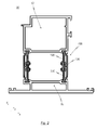
- An embodiment of such a composite profile 30 is shown in FIG Fig. 2 represented, which corresponds to a sectional view along the cutting axis II-II.
- the composite profile 30 has an inside profile chamber 11, which is connected by the insulating web 100 according to the invention with an outside profile chamber 12.
- inside profile chamber and “outside profile chamber” refer to the arrangement of the profile chambers with respect to the interior of a house or the outside atmosphere.
- outside profile chamber 12 is in direct contact with the outside atmosphere, while the inside profile chamber 11 is in contact with the room air.
- the insulating web 100 serves to connect the profile chambers 12, 13 mechanically and to separate them thermally.
- the insulating web 100 is designed to enter into a shear-resistant bond with the inside profile chamber 11 and with the outside profile chamber 12.
- the insulating web 100 for example, at its profile chambers facing ends in undercut grooves of the profile chambers by molding a metal web shear resistant connected to the profile chambers.
- insulating web 100 is integrally formed and located in a first, shear-resistant in the longitudinal direction Z state.
- This first, in the longitudinal direction Z shear-resistant state can be brought by separating the insulating strip 100 in a second, in the longitudinal direction 29ub Wars state.
- this transformation takes place in the second, in the longitudinal direction Z 29ub combat state only after the insulating web 100 is connected to the profile chambers 11, 12.
- the insulating web 100 according to the invention has a first region 110 which is connected in a shear-resistant manner to the inside profile chamber 11. As mentioned above, this shear-resistant connection with the inside profile chamber 11 can be done by setting the first area in an undercut groove of the inside profile chamber. Equivalent to this, the insulating web 100 according to the invention also has a second region 120, which is connected shear-resistant with the outer profile chamber 12. Furthermore, a third region 130 is provided, which is formed between the first and the second region 110, 120 and designed to connect the first region 110 to the second region 120 perpendicular to the longitudinal direction Z. Thus, the insulating web 100 according to the invention is also designed to accommodate a displacement movement due to thermal expansion in all spatial directions. As below with reference to Fig. 3 will be explained in more detail, the third portion 130 of the insulating web 100 may form a joint, which connects the first and second region 110, 120 movable in all three spatial directions.
- the first portion 110 has a first circular groove 111, which is located on a first end portion 110a facing away from the inside profile chamber 11.
- the second region 120 has a second one Round groove 121 on a side facing away from the outside profile chamber 12, the first end portion 120a.
- the above-mentioned third area 130 accordingly has a guide arm 131 which is designed to guide the third area 130 along the circular grooves 111, 121.
- the circular grooves 111, 121 thus represent a guide bearing for the guide arm 131 of the third region 130.
- a hinge joint is formed, which serves to increase the mobility of the insulating web 100 according to the invention, whereby relative movements of the composite profile 30 can be better absorbed.
- the guide arm 131 has, according to the in the Figures 2 and 3 In particular, a first guide element 131a for guiding the guide arm 131 along (within) the first circular groove 111 and a second guide element 131b for guiding the guide arm 131 along (within) the second circular groove 121 are shown.
- the first and second guide elements 131a, 131b are adapted in their construction to the circular grooves 111, 121.
- the guide elements 131a, 131b of the third portion 130 allow a positive connection with the circular grooves 111, 121 of the first and second portion 110, 120th Accordingly, the guide elements 131a, 131b thereby even a round construction, whereby an optimal guidance of the third Area 130 in the circular grooves 111, 121 of the first and second portions 110, 120 is achieved without jeopardizing the mechanical stability of the insulating bar 100.
- the grooves 111, 121 along the first end portions 110a, 120a have a different geometry, such as a triangular geometry or a rectangular geometry. Consequently, of course, the geometry of the guide elements 131a, 131b would be adapted to the geometry of the grooves 111, 121.
- the third region 130 is designed to form a cover profile 132, wherein the cover profile 132 extends parallel to the first and second regions 110, 120.
- the cover profile 132 gives the insulating web 100 additional stability, which improves the mechanical connection between the inside profile chamber 11 and the outside profile chamber 12.
- the third region 130 is connected in a shear-resistant manner to the first region 110 for forming a first separation region 140 on a second end region 110b of the first region 110 facing the inside profile chamber 11.
- the third region 130 is on the opposite side, ie on one of the outside Profile chamber facing second end portion 120 b of the second region 120, for forming a second separation region 150, shear-resistant connected to the second region 120.
- the severing regions 140, 150 serve to transfer the insulating bar 100 into its second state, which is in its slip-off state.
- the separation region 140, 150 can be used to divide the insulating web 100 into a plurality, preferably three, segments which can be displaced relative to one another.
- the areas 110, 120, 130 are no longer shear-resistant connected after the separation. Accordingly, results in the longitudinal direction Z a 29ubweiche sliding guide of the guide elements 131a, 131b of the guide arm 131 within the circular grooves 111, 121. Similarly, there is an increased mobility perpendicular to the longitudinal direction Z, ie in the horizontal direction X and in the vertical direction Y, since that through the Guide arm 131 formed hinge joint is no longer hindered by the shear-resistant connection with the third region 130.
- the insulating web according to the invention accordingly preferably has a notch along the first and second severing regions 140, 150.
- This notch can serve to facilitate a subdivision of the insulating web 100 according to the invention into a plurality of segments.
- first, second, and / or third portions 110, 120, 130 may have elongation-enhancing openings along the longitudinal direction Z. Accordingly, it is not only conceivable to manufacture the regions 110, 120, 130 from a solid strand, but rather the regions can have openings which reduce the shear strength of the insulating web 100 according to the invention.
- the third region 130 may be formed of a material different from the material of the first and second regions 110, 120.
- the use of different materials allows a higher flexibility of the insulating web 100 according to the invention, which advantageously again the compensation capacity of the insulating web 100 of forces perpendicular to the longitudinal direction Z, ie in the horizontal or vertical direction X, Y, is improved.
Abstract
Description
- Die Erfindung betrifft einen Isoliersteg für Fenster- und Türrahmen gemäß dem Oberbegriff des unabhängigen Patentanspruchs 1.
- Demnach betrifft die Erfindung insbesondere einen Isoliersteg zum mechanischen Verbinden eines innenseitigen Profils mit einem außenseitigen Profil. Des Weiteren betrifft die Erfindung ein Verbundprofil, welches einen erfindungsgemäßen Isoliersteg aufweist, sowie einen Fenster- oder Türrahmen, welcher aus einem erfindungsgemäßen Verbundprofil gefertigt ist.
- Aus dem Stand der Technik ist es bekannt, insbesondere Aluminium-Verbundprofile für Fenster- und Türrahmen wegen der guten Wärmeleitfähigkeit des Aluminiumwerkstoffes mittels Isolierstegen thermisch zu trennen, um die Entstehung von Kondenswasser auf der Innenschale zu vermeiden und Wärmebrücken zu vermeiden. Die Isolierstege trennen die Profilkammern des Verbundprofils thermisch, während sie andererseits eine mechanische Verbindung zwischen einer außenseitigen Profilkammer und einer innenseitigen Profilkammer des Verbundprofils bilden. Dabei ist es bekannt, die Isolierstege an ihren den Profilkammern zugewandten Enden in hinterschnittenen Nuten der Profilkammern kraftschlüssig festzulegen. Durch diese Verbindung zwischen den Isolierstegen und den Profilkammern ergibt sich eine mechanische Verbindung der Profilkammern mit dem Isoliersteg, welche zumindest in Längsrichtung des Verbundprofils bzw. des Isolierstegs schubfest ist. Diese schubfeste mechanische Verbindung in Längsrichtung des Verbundprofils zwischen den Isolierstegen und den Profilkammern nimmt beim Angriff von statischen oder dynamischen Lasten (zum Beispiel Windstößen) die resultierenden Schubkräfte auf und wirkt somit einer Durchbiegung des Verbundprofils entgegen. Derartige mechanische Verbindungen werden allgemein als "schubfeste Verbindungen" bezeichnet.
- Gerade bei Fenster- und Türrahmen bzw. Pfosten-Riegel-Konstruktionen, welche sich an der Außenfassade eines Gebäudes befinden, ist die außenseitige Profilkammer oftmals einer anderen Temperatur ausgesetzt als es für die innenseitige Profilkammer der Fall ist. So ist die außenseitige Profilkammer, beispielsweise in den Wintermonaten, einer niedrigeren Temperatur ausgesetzt als die innenseitige Profilkammer. Dementsprechend führt die Ausbildung dieses Temperaturgefälles dazu, dass die beiden Profilkammern eine unterschiedliche Wärmeausdehnung erfahren, wodurch eine Relativbewegung der Profilkammern entsteht. Aus diesem Grund kommt es bei den aus dem Stand der Technik bekannten schubfesten Isolierstegen zu einem Verzug der Verbundprofile mit negativen Begleiterscheinungen wie beispielsweise Undichtigkeit und/oder Funktionsstörungen der Tür bzw. des Fensters, dessen Rahmen aus einem schubfesten Verbundprofil gefertigt wurde. Insbesondere kommt es demnach vor allem bei Türen häufig dazu, dass die Schließfunktion der Schlösser nicht mehr gegeben ist, da die Schlösser unter mechanischer Spannung geraten und somit nicht mehr betätigbar sind.
- In diesem Zusammenhang ist es aus dem Stand der Technik bekannt, so genannte verschubweiche Isolierstege zu verwenden. Der Begriff "verschubweich" beschreibt die Eigenschaft der betreffenden Isolierstege, eine Relativbewegung in Längsrichtung des Verbundprofils zuzulassen.
- Insbesondere ist es bekannt, den Isoliersteg zweiteilig auszuführen, um eine Gleitführung in Längsrichtung des Verbundprofils zu ermöglichen. Diese aus dem Stand der Technik bekannte Gleitführung stellt dabei sicher, dass die durch Erwärmung des Verbundprofils bedingten Längeausdehnungsunterschiede nicht zu einer unzulässig hohen Durchbiegung des Verbundprofils führen können.
- In diesem Zusammenhang sei auf die Druckschrift
EP 0 829 609 B1 verwiesen. Dieser Stand der Technik betrifft ein wärmegedämmtes Verbundprofil für Türen, Fenster oder Fassaden mit einem Isoliersteg, welcher zweiteilig ausgebildet ist und eine als Gleitführung ausgebildete mittige Verbindung zwischen den beiden Teilen des Isolierstegs aufweist. Folglich ermöglicht der aus derEP 0 829 609 B1 bekannte Isoliersteg eine Relativbewegung der außenseitigen Profilkammer gegenüber der innenseitigen Profilkammer in Längsrichtung des Verbundprofils. - Die oben genannten aus dem Stand der Technik bekannten zweiteilig ausgeführten Isolierstege weisen jedoch das Problem auf, dass ungewollte Relativbewegungen der Profilkammern zueinander (z.B. aufgrund von Windstößen) nicht verhindert werden können. Des Weiteren ermöglichen die bekannten Isolierstege zwar eine Kompensation von Verschiebungsbewegungen in Längsrichtung des Verbundprofils, jedoch sind sie meist nicht dazu ausgestaltet, Relativbewegungen in horizontaler oder vertikaler Richtung zu kompensieren. Ferner bringen die bekannten zweiteilig ausgeführten Isolierstege einen hohen Herstellungs- und Montageaufwand mit sich. So müssen die zweiteiligen Isolierstege hohe Toleranzanforderungen erfüllen, um nach der Montage eine ausreichend hohe mechanische Verbindung zwischen den Profilkammern des Verbundprofils zu gewährleisten.
- Aufgrund oben genannter Problemstellung liegt der vorliegenden Erfindung die Aufgabe zugrunde, einen Isoliersteg für Fenster- und Türrahmen anzugeben, welcher in der Lage ist, Verschiebungen des Verbundprofils aufgrund von Wärmeausdehnung in allen Raumrichtungen auszugleichen. Darüber hinaus ist es Aufgabe der Erfindung einen Isoliersteg so auszugestalten, dass dieser einfach hergestellt werden kann und eine einfache Montage ermöglicht.
- Diese Aufgabe wird erfindungsgemäß durch den kennzeichnenden Teil des unabhängigen Patentanspruchs 1 gelöst.
- Demnach zeichnet sich der erfindungsgemäße Isoliersteg für Fenster- und Türrahmen dadurch aus, dass dieser einteilig ausgebildet ist und von einem ersten, in Längsrichtung schubfesten Zustand in einen zweiten, in Längsrichtung verschubweichen Zustand bringbar ist.
- Der erfindungsgemäße Isoliersteg hat den Vorteil, dass er einteilig ausgebildet ist und somit in einem Arbeitsschritt hergestellt werden kann. Demzufolge ist es nicht nur möglich, den Herstellungsprozess des Isolierstegs zu vereinfachen, vielmehr wird auch eine Vereinfachung der Montage des erfindungsgemäßen Isolierstegs an den Profilen bzw. Profilkammern des Verbundprofils erreicht. Da der erfindungsgemäße Isoliersteg in einem ersten Zustand schubfest ausgebildet ist, ist es ferner auch möglich, diesen für Fenster- und Türrahmen zu verwenden, welche keiner Verschubweichheit bedürfen. Außerdem ist es denkbar, dass vereinzelte Isolierstege des Verbundprofils eines Fenster oder Türrahmens in ihrem schubfesten Zustand belassen werden, während andere Isolierstege den zweiten, in Längsrichtung verschubweichen Zustand aufweisen, um Ausdehnungen aufgrund von Wärmeunterschieden zu kompensieren. Es ist folglich möglich, dass die Verschubweichheit des Verbundprofils jederzeit individuell eingestellt werde kann, um das Verbundprofil den örtlichen Witterungsbedingungen anzupassen.
- Vorteilhafte Weiterbildungen des erfindungsgemäßen Isolierstegs sind in den abhängigen Ansprüchen angegeben.
- So ist in einer vorteilhaften Realisierung des erfindungsgemäßen Isolierstegs vorgesehen, dass der Isoliersteg einen ersten Bereich, welcher mit dem innenseitigen Profil schubfest verbunden ist, und einen zweiten Bereich, welcher mit der außenseitigen Profilkammer verbunden ist, aufweist. Darüber hinaus weist der Isoliersteg einen dritten Bereich auf, welcher zwischen dem ersten und dem zweiten Bereich gebildet und ausgelegt ist, den ersten Bereich senkrecht zur Längsrichtung beweglich mit dem zweiten Bereich zu verbinden. Somit ist der erfindungsgemäße Isoliersteg gemäß dieser Ausführungsform auch dazu ausgelegt, eine Verschubweichheit, nicht nur in Längsrichtung des Verbundprofils, zu ermöglichen. Vielmehr ist es vorzugsweise möglich, dass der Isoliersteg Verschiebungsbewegungen aufgrund von Wärmeausdehnung in allen Raumrichtungen aufnehmen kann. Wie es im Folgenden näher erläutert wird, kann der dritte Bereich des Isolierstegs demgemäß derart ausgestaltet sein, dass dieser ein Gelenk ausbildet, welches den ersten und zweiten Bereich in allen drei Raumrichtungen beweglich miteinander verbindet. Folglich ist es durch den erfindungsgemäßen Isoliersteg auch möglich, Verschiebungsbewegungen der Profile senkrecht zur Längsrichtung des Verbundprofils aufzunehmen.
- Gemäß einer weiteren Ausführungsform des erfindungsgemäßen Isolierstegs weist der erste Teilbereich eine erste Rundnut an einem von dem innenseitigen Profil abgewandten ersten Endbereich und der zweite Bereich eine zweite Rundnut an einem von dem außenseitigen Profil abgewandten ersten Endbereich auf. Darüber hinaus weist der dritte Bereich einen Führungsarm zum Führen des dritten Bereichs innerhalb der Rundnuten auf. Durch das Vorsehen von Rundnuten an den Endbereichen des ersten und zweiten Bereichs entsteht ein besonders vorteilhaftes Führungslager für den Führungsarm des dritten Bereichs. Folglich wird zwischen den Bereichen ein besonders vorteilhaftes Scharniergelenk ausgebildet, welches dazu dient, die Beweglichkeit des erfindungsgemäßen Isolierstegs zu erhöhen, wodurch Relativbewegungen des Verbundprofils noch besser aufgenommen werden können.
- Nach einer weiteren Ausführungsform weist der oben genannte Führungsarm ein erstes Führungselement zum Führen des Führungsarms entlang der ersten Rundnut, sowie ein zweites Führungselement zum Führen des Führungsarms entlang der zweiten Rundnut auf. Vorteilhafter Weise sind diese ersten und zweiten Führungselemente in ihrer Konstruktion auf die Rundnuten angepasst. Dadurch ermöglichen die Führungselemente des dritten Bereichs eine formschlüssige Verbindung mit den Rundnuten des ersten bzw. zweiten Bereichs. Selbstverständlich ist es auch denkbar, dass es sich bei den Nuten um hinterschnittene eckige Nuten handelt, wobei jedoch die erfindungsgemäßen Rundnuten eine höhere Beweglichkeit des Verbundprofils gewährleisten.
- Ferner ist es gemäß einer weiteren Umsetzung vorgesehen, dass der dritte Bereich dazu ausgelegt ist, ein Abdeckprofil, welches parallel zum ersten und zweiten Bereich verläuft, auszubilden. Ein solches Abdeckprofil kann dazu genutzt werden, dem Isoliersteg eine zusätzliche Stabilität zu verleihen und folglich die mechanische Verbindung zwischen dem innenseitigen Profil und dem außenseitigen Profil zu verbessern. Ferner ist es vorstellbar, dass ein solches Abdeckprofil die Wärmeisolation zwischen den beiden Profilen weiter verbessert. Das Abdeckprofil ist vorzugsweise so konstruiert, dass dieses die Ausmaße des Isolierstegs nicht unzweckmäßig vergrößert.
- In einer weiteren Realisierung ist der dritte Bereich des Isolierstegs zum Ausbilden eines ersten Auftrennbereichs an einem dem innenseitigen Profil zugewandten zweiten Endbereich des ersten Bereichs schubfest mit dem ersten Bereich verbunden. Darüber hinaus ist der dritte Bereich in vorteilhafter Weise zum Ausbilden eines zweiten Auftrennbereichs an einem dem außenseitigen Profil zugewandten zweiten Endbereich des zweiten Bereichs schubfest mit dem zweiten Bereich verbunden.
- Wie oben bereits erwähnt, ist der erfindungsgemäße Isoliersteg zunächst einteilig, d.h. in Längsrichtung schubfest ausgebildet. Um jedoch den erfindungsgemäßen Isoliersteg in einen verschubweichen Zustand zu überführen, ist es nötig, diesen zumindest bereichsweise aufzutrennen. Zu diesem Zweck ist der erfindungsgemäße dritte Bereich des Isolierstegs schubfest mit dem ersten und zweiten Bereich des Isolierstegs verbunden und bildet somit Auftrennbereiche, welche dazu genutzt werden können den Isoliersteg in mehrere, vorzugsweise drei zueinander verschiebbare Segmente zu unterteilen. Demnach kann der Isoliersteg in vorteilhafter Weise, je nach Anforderung an die mechanische Verbindung des Verbundprofils, in zwei oder mehrere Teile unterteilt werden.
- Der Isoliersteg kann gemäß einer weiteren Ausführungsform der Erfindung eine Kerbe entlang des ersten und zweiten Auftrennbereichs aufweisen. Diese Kerbe kann dazu genutzt werden, den erfindungsgemäßen Isoliersteg auf einfache Weise, auch nach dem Einsetzen in das Verbundprofil, in mehrere Segmente zu unterteilen. So ist es vorstellbar, den dritten Bereich entlang der Kerbe, beispielsweise mit Hilfe eines Messers, vom ersten bzw. zweiten Bereich zu trennen. Alternativ ist es auch denkbar, dass der Isoliersteg Perforationen entlang des ersten und zweiten Auftrennbereichs aufweist.
- Gemäß einer weiteren Ausführungsform des erfindungsgemäßen Isolierstegs, weist der erste Bereich und/oder der zweite Bereich und/oder der dritte Bereich entlang der Längsrichtung Öffnungen zur Verbesserung der Dehnbarkeit auf. Es ist demnach nicht zwingend notwendig, dass der erfindungsgemäße Isoliersteg an allen Bereichen durchgehend solide ausgebildet ist. Vielmehr kann der Isoliersteg Öffnungen verschiedener Ausdehnung entlang der Längsrichtung aufweisen, welche die Steifigkeit der mechanischen Verbindung herabsetzen und somit dazu beitragen, dass Relativbewegungen der Profile aufgrund von Wärmeausdehnungen besser durch den Isoliersteg kompensiert werden können.
- Gemäß einem weiteren Aspekt kann der dritte Bereich des Isolierstegs aus einem Material gebildet sein, welches sich von dem Material des ersten und zweiten Bereichs unterscheidet. Insbesondere kann es vorteilhaft sein, den dritten Bereich aus einem Material zu fertigen, welches weicher ist als das Material, aus welchem der erste und der zweite Bereich gebildet sind. In diesem Zusammenhang ist es beispielsweise denkbar, den dritten Bereich aus Polyamid, Polyester oder Polypropylen zu bilden. Die Verwendung von unterschiedlichen Materialen ermöglicht eine höher Flexibilität des erfindungsgemäßen Isolierstegs, wodurch in vorteilhafter Weise abermals das Kompensationsvermögen des Isolierstegs von Kräften senkrecht zur Längsrichtung verbessert wird. Zu diesem Zweck kann es jedoch nötig sein, den dritten Bereich erst nach der Herstellung mit dem ersten und zweiten Bereich entlang der Auftrennbereiche zu verbinden (z. B. verkleben).
- Im Folgenden wird der erfindungsgemäße Isoliersteg mit Bezug auf die in den Figuren dargestellten Ausführungsbeispielen näher beschrieben. Dabei zeigen:
- Fig. 1
- eine Frontansicht eines Türrahmens;
- Fig. 2
- eine Schnittdarstellung einer Ausführungsform eines erfindungsgemäßen Verbundprofils entlang der in
Fig. 1 dargestellten Schnittachse II-II; und - Fig. 3
- eine vergrößerte Darstellung des Verbundprofils nach
Fig. 2 mit erfindungsgemäßem Isoliersteg. - Im Folgenden sind gleiche oder gleich wirkende Bauteile aus Gründen der Übersichtlichkeit mit gleichen Bezugszeichen versehen.
- In
Fig. 1 ist eine Tür mit einem erfindungsgemäßen Türrahmen 1 dargestellt. Selbstverständlich ist die Erfindung nicht auf die Konstruktion von Türrahmen 1 beschränkt, sondern kann ebenfalls zur Herstellung von Fensterrahmen oder Riegel-Pfosten-Konstruktionen verwendet werden. Vorzugsweise weist der Türrahmen 1 entlang des ganzen Rahmens dasselbe Verbundprofil auf. Eine Ausführungsform eines solchen Verbundprofils 30 ist inFig. 2 dargestellt, welche einer Schnittdarstellung entlang der Schnittachse II-II entspricht. - Das Verbundprofil 30 weist eine innenseitige Profilkammer 11 auf, die durch den erfindungsgemäßen Isoliersteg 100 mit einer außenseitigen Profilkammer 12 verbunden ist. Dabei beziehen sich die Bezeichnungen "innenseitige Profilkammer" und "außenseitige Profilkammer" auf die Anordnung der Profilkammern bezüglich des Innenraums eines Hauses bzw. der Außenatmosphäre. Mit anderen Worten steht die außenseitige Profilkammer 12 in direktem Kontakt mit der Außenatmosphäre, während die innenseitige Profilkammer 11 mit der Raumluft in Kontakt steht.
- Der erfindungsgemäße Isoliersteg 100 dient dazu, die Profilkammern 12, 13 mechanisch zu verbinden und diese thermisch zu trennen. Zu diesem Zweck ist der Isoliersteg 100 dazu ausgelegt, einen schubfesten Verbund mit der innenseitigen Profilkammer 11 sowie mit der außenseitigen Profilkammer 12 einzugehen. Dazu kann der Isoliersteg 100 beispielsweise an seinen den Profilkammern zugewandten Enden in hinterschnittene Nuten der Profilkammern durch Anformen eines Metallstegs schubfest mit den Profilkammern verbunden werden.
- Der in den
Figuren 2 und3 dargestellte, erfindungsgemäße Isoliersteg 100 ist einteilig ausgebildet und befindet sich in einem ersten, in Längsrichtung Z schubfesten Zustand. Dieser erste, in Längsrichtung Z schubfeste Zustand kann durch Auftrennen des Isolierstegs 100 in einen zweiten, in Längsrichtung verschubweichen Zustand gebracht werden. Vorteilhafter Weise erfolgt diese Umformung in den zweiten, in Längsrichtung Z verschubweichen Zustand erst nachdem der Isoliersteg 100 mit den Profilkammern 11, 12 verbunden ist. - Insbesondere weist der erfindungsgemäße Isoliersteg 100 einen ersten Bereich 110 auf, welcher mit der innenseitigen Profilkammer 11 schubfest verbunden ist. Wie oben bereits erwähnt, kann diese schubfeste Verbindung mit der innenseitigen Profilkammer 11 durch das Festlegen des ersten Bereichs in einer hinterschnittenen Nut der innenseitigen Profilkammer erfolgen. Äquivalent dazu weist der erfindungsgemäße Isoliersteg 100 ferner einen zweiten Bereich 120 auf, welcher mit der außenseitigen Profilkammer 12 schubfest verbunden ist. Ferner ist ein dritter Bereich 130 vorgesehen, welcher zwischen dem ersten und dem zweiten Bereich 110, 120 gebildet und ausgelegt ist, den ersten Bereich 110 senkrecht zur Längsrichtung Z beweglich mit dem zweiten Bereich 120 zu verbinden. Somit ist der erfindungsgemäße Isoliersteg 100 auch dazu ausgelegt, eine Verschiebungsbewegung aufgrund von Wärmeausdehnung in allen Raumrichtungen aufzunehmen. Wie im Folgenden mit Bezug auf
Fig. 3 näher erläutert werden wird, kann der dritte Bereich 130 des Isolierstegs 100 dazu ein Gelenk ausbilden, welches den ersten und zweiten Bereich 110, 120 in allen drei Raumrichtungen beweglich miteinander verbindet. - Wie in
Fig. 3 dargestellt, weist der erste Bereich 110 eine erste Rundnut 111 auf, welche sich an einem von der innenseitigen Profilkammer 11 abgewandten, ersten Endbereich 110a befindet. Gleichfalls weist der zweite Bereich 120 eine zweite Rundnut 121 an einem von der außenseitigen Profilkammer 12 abgewandten, ersten Endbereich 120a auf. Der oben erwähnte dritte Bereich 130 weist dementsprechend einen Führungsarm 131 auf, welcher ausgelegt ist, den dritten Bereich 130 entlang der Rundnuten 111, 121 zu führen. Die Rundnuten 111, 121 stellen folglich ein Führungslager für den Führungsarm 131 des dritten Bereichs 130 dar. Es wird somit ein Scharniergelenk ausgebildet, welches dazu dient, die Beweglichkeit des erfindungsgemäßen Isolierstegs 100 zu erhöhen, wodurch Relativbewegungen des Verbundprofils 30 noch besser aufgenommen werden können. - Der Führungsarm 131 weist, gemäß der in den
Figuren 2 und3 dargestellten Ausführungsform insbesondere ein erstes Führungselement 131a zum Führen des Führungsarms 131 entlang (innerhalb) der ersten Rundnut 111, sowie ein zweites Führungselement 131b zum Führen des Führungsarms 131 entlang (innerhalb) der zweiten Rundnut 121 auf. Die ersten und zweiten Führungselemente 131a, 131b sind in ihrer Konstruktion auf die Rundnuten 111, 121 angepasst. Dadurch ermöglichen die Führungselemente 131a, 131b des dritten Teilbereichs 130 eine formschlüssige Verbindung mit den Rundnuten 111, 121 des ersten bzw. zweiten Teilbereichs 110, 120. Dementsprechend weisen die Führungselemente 131a, 131b dabei selbst eine runde Konstruktion auf, wodurch eine optimale Führung des dritten Bereichs 130 in den Rundnuten 111, 121 des ersten und zweiten Bereichs 110, 120 erreicht wird, ohne die mechanische Stabilität des Isolierstegs 100 zu gefährden. Selbstverständlich ist es auch denkbar, dass die Nuten 111, 121 entlang der ersten Endbereiche 110a, 120a eine andere Geometrie, wie beispielsweise eine Dreiecksgeometrie oder eine Rechtecksgeometrie, aufweisen. Folglich wäre selbstverständlich auch die Geometrie der Führungselemente 131a, 131b an die Geometrie der Nuten 111, 121 anzupassen. - Wie es ferner der
Fig. 3 zu entnehmen ist, ist der dritte Bereich 130 ausgelegt, ein Abdeckprofil 132 auszubilden, wobei das Abdeckprofil 132 parallel zum ersten und zweiten Bereich 110, 120 verläuft. Das Abdeckprofil 132 verleiht dem Isoliersteg 100 zusätzliche Stabilität, was die mechanische Verbindung zwischen der innenseitigen Profilkammer 11 und der außenseitigen Profilkammer 12 verbessert. - Der dritte Bereich 130 ist zum Ausbilden eines ersten Auftrennbereichs 140 an einem der innenseitigen Profilkammer 11 zugewandten zweiten Endbereich 110b des ersten Bereichs 110 schubfest mit dem ersten Bereich 110 verbunden. Ähnlich dazu ist der dritte Bereich 130 auf der Gegenseite, d.h. an einem der außenseitigen Profilkammer zugewandten zweiten Endbereich 120b des zweiten Bereichs 120, zum Ausbilden eines zweiten Auftrennbereichs 150, schubfest mit dem zweiten Bereich 120 verbunden. Die Auftrennbereiche 140, 150 dienen dazu, den Isoliersteg 100 in seinen verschubweichen, zweiten Zustand zu überführen. Insbesondere können die Auftrennbereich 140, 150 dazu genutzt werden, den Isoliersteg 100 in mehrere, vorzugsweise drei, zueinander verschiebbare Segmente zu unterteilen. Das heißt, dass die Bereiche 110, 120, 130 nach dem Auftrennen nicht mehr schubfest verbunden sind. Dementsprechend ergibt sich in Längsrichtung Z eine verschubweiche Gleitführung der Führungselemente 131a, 131b des Führungsarms 131 innerhalb der Rundnuten 111, 121. Gleichermaßen ergibt sich eine erhöhte Beweglichkeit senkrecht zur Längsrichtung Z, d.h. in horizontaler Richtung X sowie in vertikaler Richtung Y, da das durch den Führungsarm 131 gebildete Scharniergelenk nicht mehr durch die schubfeste Verbindung mit dem dritten Bereich 130 behindert wird.
- Vorzugsweise weist der erfindungsgemäße Isoliersteg dementsprechend eine Kerbe entlang des ersten und zweiten Auftrennbereichs 140, 150 auf. Diese Kerbe kann dazu dienen, eine Unterteilung des erfindungsgemäßen Isolierstegs 100 in mehrere Segmente zu erleichtern. Selbstverständlich ist es auch denkbar, anstatt einer Kerbe eine Perforation entlang des ersten und zweiten Auftrennbereichs 140, 150 vorzusehen.
- Obwohl es nicht in den Figuren dargestellt ist, können der erste, zweite und/oder dritte Bereich 110, 120, 130 entlang der Längsrichtung Z Öffnungen zur Verbesserung der Dehnbarkeit aufweisen. Dementsprechend ist es nicht nur denkbar, die Bereiche 110, 120, 130 aus einem soliden Strang zu fertigen, vielmehr können die Bereiche Öffnungen aufweisen, welche die Schubfestigkeit des erfindungsgemäßen Isolierstegs 100 herabsetzen.
- Schließlich kann der dritte Bereich 130 aus einem Material gebildet sein, welches sich von dem Material des ersten und zweiten Bereichs 110, 120 unterscheidet. Insbesondere ist es dabei vorteilhaft, den dritten Bereich aus einem weicheren Material zu fertigen. Die Verwendung von unterschiedlichen Materialen ermöglicht eine höher Flexibilität des erfindungsgemäßen Isolierstegs 100, wodurch vorteilhafter Weise abermals das Kompensationsvermögen des Isolierstegs 100 von Kräften senkrecht zur Längsrichtung Z, d.h. in horizontaler bzw. vertikaler Richtung X, Y, verbessert wird.
-
- 1
- Türrahmen
- 11
- innenseitige Profilkammer
- 12
- außenseitige Profilkammer
- 30
- Verbundprofil
- 100
- Isoliersteg
- 110
- erster Teilbereich
- 110a
- erster Endbereich des ersten Teilbereichs
- 110b
- zweiter Endbereich des ersten Teilbereichs
- 111
- erste Rundnut
- 120
- zweiter Teilbereich
- 120a
- erster Endbereich des zweiten Teilbereichs
- 120b
- zweiter Endbereich des zweiten Teilbereichs
- 121
- zweite Rundnut
- 130
- dritter Teilbereich
- 131
- Führungsarm
- 131a
- erstes Führungselement
- 131b
- zweites Führungselement
- 140
- erster Auftrennbereich
- 150
- zweiter Auftrennbereich
- X
- horizontale Richtung
- Y
- vertikale Richtung
- Z
- Längsrichtung
Claims (11)
- Isoliersteg (100), insbesondere für Fenster- und Türrahmen (1), zum mechanischen Verbinden eines ersten innenseitigen Profils (11) mit einem zweiten außenseitigen Profil (12), wobei der Isoliersteg (100) ausgelegt ist, einen schubfesten Verbund mit dem innenseitigen Profil (11) und dem außenseitigen Profil (12) einzugehen,
dadurch gekennzeichnet,
dass der Isoliersteg (100) einteilig ausgebildet ist und von einem ersten, in Längsrichtung (Z) des Isolierstegs (100) schubfesten Zustand in einen zweiten, in Längsrichtung (Z) des Isolierstegs (100) verschubweichen Zustand bringbar ist. - Isoliersteg (100) nach Anspruch 1, wobei der Isoliersteg (100) aufweist:- einen ersten Bereich (110), welcher mit dem innenseitigen Profil (11) schubfest verbindbar ist;- einen zweiten Bereich (120), welcher mit dem außenseitigen Profil (12) schubfest verbindbar ist; und- einen dritten Bereich (130), welcher zwischen dem ersten und dem zweiten Bereich (110, 120) gebildet und ausgelegt ist, den ersten Bereich (110) senkrecht zur Längsrichtung (Z) des Isolierstegs (100) beweglich mit dem zweiten Bereich (120) zu verbinden.
- Isoliersteg (100) nach Anspruch 2,
wobei der erste Bereich (110) eine Rundnut (111) an einem von dem innenseitigen Profil (11) abgewandten ersten Endbereich (110a) und der zweite Bereich (120) eine Rundnut (121) an einem von dem außenseitigen Profil (12) abgewandten ersten Endbereich (120a) aufweist, und wobei der dritte Bereich (130) einen Führungsarm (131) aufweist zum Führen des dritten Bereichs (130) entlang der Rundnuten (111, 121). - Isoliersteg (100) nach Anspruch 3,
wobei der Führungsarm (131) ein erstes Führungselement (131a) zum Führen des Führungsarms (131) entlang der Rundnut (111), sowie ein zweites Führungselement (131b) zum Führen des Führungsarms (131) entlang der Rundnut (121) des zweiten Bereichs (120) aufweist. - Isoliersteg (100) nach einem der Ansprüche 2 bis 4,
wobei der dritte Bereich (130) ausgelegt ist, ein Abdeckprofil (132), welches parallel zum ersten und zweiten Bereich (110, 120) verläuft, auszubilden. - Isoliersteg (100) nach einem der Ansprüche 2 bis 5,
wobei der dritte Bereich (130) an einem dem innenseitigen Profil (11) zugewandten zweiten Endbereich (110b) des ersten Bereichs (110) schubfest mit dem ersten Bereich (110) verbunden ist, zum Ausbilden eines ersten Auftrennbereichs (140) und wobei der dritte Bereich (130) an einem dem außenseitigen Profil (12) zugewandten zweiten Endbereich (120b) des zweiten Bereichs (120) schubfest mit dem zweiten Bereich (120) verbunden ist zum Ausbilden eines zweiten Auftrennbereichs (150). - Isoliersteg (100) nach Anspruch 6,
wobei der Isoliersteg (100) eine Kerbe entlang des ersten und zweiten Auftrennbereichs (140, 150) aufweist. - Isoliersteg (100) nach einem der Ansprüche 2 bis 7,
wobei der erste Bereich (110) und/oder der zweite Bereich (120) und/oder der dritte Bereich (130) entlang der Längsrichtung (Z) des Isolierstegs (100) Öffnungen zur Verbesserung der Dehnbarkeit aufweist. - Isoliersteg (100) nach einem der Ansprüche 2 bis 8,
wobei der dritte Bereich (130) aus einem Material gebildet ist, welches sich von dem Material des ersten und zweiten Bereichs (110, 120) unterscheidet. - Wärmegedämmtes Verbundprofil (30) mit einem innenseitigen Profil, insbesondere Profilkammer (11) und einem außenseitigen Profil, insbesondere Profilkammer (12), wobei das Verbundprofil einen Isoliersteg (100) nach einem der Ansprüche 1 bis 9 aufweist, wobei der Isoliersteg (100) ausgelegt ist, die Profile (11, 12) des Verbundprofils (30) mechanisch zu verbinden und thermisch zu trennen.
- Fenster- oder Türrahmen (1) mit einem wärmegedämmten Verbundprofil (30) nach Anspruch 10.
Priority Applications (1)
| Application Number | Priority Date | Filing Date | Title |
|---|---|---|---|
| EP12167637.3A EP2530230B1 (de) | 2011-05-30 | 2012-05-11 | Isoliersteg für Fenster- und Türrahmen |
Applications Claiming Priority (2)
| Application Number | Priority Date | Filing Date | Title |
|---|---|---|---|
| EP11168037 | 2011-05-30 | ||
| EP12167637.3A EP2530230B1 (de) | 2011-05-30 | 2012-05-11 | Isoliersteg für Fenster- und Türrahmen |
Publications (3)
| Publication Number | Publication Date |
|---|---|
| EP2530230A2 true EP2530230A2 (de) | 2012-12-05 |
| EP2530230A3 EP2530230A3 (de) | 2015-01-21 |
| EP2530230B1 EP2530230B1 (de) | 2016-12-28 |
Family
ID=46026740
Family Applications (1)
| Application Number | Title | Priority Date | Filing Date |
|---|---|---|---|
| EP12167637.3A Active EP2530230B1 (de) | 2011-05-30 | 2012-05-11 | Isoliersteg für Fenster- und Türrahmen |
Country Status (1)
| Country | Link |
|---|---|
| EP (1) | EP2530230B1 (de) |
Cited By (4)
| Publication number | Priority date | Publication date | Assignee | Title |
|---|---|---|---|---|
| WO2015169671A1 (de) * | 2014-05-05 | 2015-11-12 | SCHÜCO International KG | Verbundprofil für türen, fenster oder fassadenelemente |
| DE102016119580A1 (de) * | 2016-10-13 | 2018-04-19 | Ensinger Gmbh | Kunststoffprofil für ein Metall-Kunststoff-Verbundprofil |
| RU2694378C2 (ru) * | 2014-05-05 | 2019-07-12 | Шюко Интернациональ Кг | Составной профиль для дверей, окон или фасадных элементов |
| DE102019110178A1 (de) * | 2019-04-17 | 2020-10-22 | HUECK System GmbH & Co. KG | Isoliersteg |
Citations (1)
| Publication number | Priority date | Publication date | Assignee | Title |
|---|---|---|---|---|
| EP0829609B1 (de) | 1996-09-17 | 2001-05-09 | SCHÜCO International KG | Wärmegedämmtes Verbundprofil für Türen, Fenster oder Fassaden |
Family Cites Families (4)
| Publication number | Priority date | Publication date | Assignee | Title |
|---|---|---|---|---|
| DE2729021C2 (de) * | 1977-06-28 | 1982-02-04 | Wieland-Werke Ag, 7900 Ulm | Verfahren zur Herstellung eines wärmegedämmten Verbundprofils für Fenster, Türen o.dgl. |
| DE202007004804U1 (de) * | 2007-03-30 | 2007-06-14 | SCHÜCO International KG | Isolierleiste für ein wärmegedämmtes Verbundprofil für Türen, Fenster oder Fassaden |
| DE102008047331C5 (de) * | 2008-09-16 | 2016-09-08 | Hueck Gmbh & Co. Kg | Verfahren zur Herstellung eines Verbundprofils |
| DE102009054178B3 (de) * | 2009-11-21 | 2011-06-01 | Norsk Hydro Asa | Verfahren zur Herstellung eines wärmegedämmten Verbundprofils |
-
2012
- 2012-05-11 EP EP12167637.3A patent/EP2530230B1/de active Active
Patent Citations (1)
| Publication number | Priority date | Publication date | Assignee | Title |
|---|---|---|---|---|
| EP0829609B1 (de) | 1996-09-17 | 2001-05-09 | SCHÜCO International KG | Wärmegedämmtes Verbundprofil für Türen, Fenster oder Fassaden |
Cited By (10)
| Publication number | Priority date | Publication date | Assignee | Title |
|---|---|---|---|---|
| WO2015169671A1 (de) * | 2014-05-05 | 2015-11-12 | SCHÜCO International KG | Verbundprofil für türen, fenster oder fassadenelemente |
| US9920568B2 (en) | 2014-05-05 | 2018-03-20 | SCHÜCO International KG | Composite profile for doors, windows or façade elements |
| RU2694378C2 (ru) * | 2014-05-05 | 2019-07-12 | Шюко Интернациональ Кг | Составной профиль для дверей, окон или фасадных элементов |
| RU2695526C2 (ru) * | 2014-05-05 | 2019-07-23 | Шюко Интернациональ Кг | Составной профиль для дверей, окон или фасадных элементов |
| CN113153077A (zh) * | 2014-05-05 | 2021-07-23 | 许克国际两合公司 | 用于门、窗或建筑物外立面元件的复合型材 |
| CN113236078A (zh) * | 2014-05-05 | 2021-08-10 | 许克国际两合公司 | 用于门、窗或立面元件的复合型材 |
| DE102016119580A1 (de) * | 2016-10-13 | 2018-04-19 | Ensinger Gmbh | Kunststoffprofil für ein Metall-Kunststoff-Verbundprofil |
| US11414917B2 (en) | 2016-10-13 | 2022-08-16 | Ensinger Gmbh | Profiled plastic section for a metal/plastic composite profiled section |
| US11873674B2 (en) | 2016-10-13 | 2024-01-16 | Ensinger Gmbh | Profiled plastic section for a metal/plastic composite profiled section |
| DE102019110178A1 (de) * | 2019-04-17 | 2020-10-22 | HUECK System GmbH & Co. KG | Isoliersteg |
Also Published As
| Publication number | Publication date |
|---|---|
| EP2530230B1 (de) | 2016-12-28 |
| EP2530230A3 (de) | 2015-01-21 |
Similar Documents
| Publication | Publication Date | Title |
|---|---|---|
| EP0153758A2 (de) | Verbundstab, insbesondere für Fensterrahmen, Türrahmen und Rolläden | |
| EP2527580B1 (de) | Isolationseinsatz für einen aus Profilen gebildeten Rahmen | |
| EP3348729A1 (de) | Brandschutzprofil, brandschutzfugenbaugruppe und verfahren zur montage einer brandschutzfugenbaugruppe | |
| EP1024243B1 (de) | Brandsichere Isolierstegverbindung | |
| EP2530230B1 (de) | Isoliersteg für Fenster- und Türrahmen | |
| DE202010001301U1 (de) | Wärmegedämmtes Verbundprofil | |
| DE202010008921U1 (de) | Mitteldichtung für hoch wärmegedämmte Fenster oder Türen | |
| EP3246505B1 (de) | Verbundprofil für türen, fenster oder fassadenelemente | |
| EP0117308B1 (de) | Durch ein Metallprofil verstärktes Kunststoffhohlprofil und Rahmen | |
| DE102005035279A1 (de) | Fensterprofil | |
| EP1932998A1 (de) | Verbundprofil und Verfahren zur Herstellung eines Verbundprofils | |
| EP3184723A1 (de) | Verbundprofil für fenster, türen oder dergleichen | |
| DE102009054178B3 (de) | Verfahren zur Herstellung eines wärmegedämmten Verbundprofils | |
| EP1002924A2 (de) | Wärmegedämmtes Verbundprofil, insbesondere für Fenster, Türen, Fassaden und dergleichen | |
| WO2015169668A1 (de) | Verbundprofil für türen, fenster oder fassadenelemente | |
| EP3140484B1 (de) | Verbundprofil für türen, fenster oder fassadenelemente | |
| EP2787159B1 (de) | Profilanordnung mit Isoliereinsatz | |
| EP3438395B1 (de) | Fensterrahmensystem | |
| DE102014112145A1 (de) | Verbundprofil für Türen, Fenster oder Fassadenelemente | |
| DE102020106696A1 (de) | Fenster mit einem Lüftungskanal | |
| EP2754839A1 (de) | Rahmen oder T-Verbindung und Verfahren zur Montage eines Rahmens oder einer T-Verbindung | |
| DE102013018274A1 (de) | Thermisch gedämmtes Profil | |
| EP2942468B1 (de) | Verbundprofil für türen, fenster oder fassadenelemente | |
| EP2439371A2 (de) | Anordnung bestehend aus einer Dichtungsanordnung und einem Schiebefenster oder einer Schiebetür | |
| EP1703064A1 (de) | Verfahren zur Verbindung von Fensterelementen innerhalb einer Fensterfront und Kopplungssystem dafür |
Legal Events
| Date | Code | Title | Description |
|---|---|---|---|
| PUAI | Public reference made under article 153(3) epc to a published international application that has entered the european phase |
Free format text: ORIGINAL CODE: 0009012 |
|
| AK | Designated contracting states |
Kind code of ref document: A2 Designated state(s): AL AT BE BG CH CY CZ DE DK EE ES FI FR GB GR HR HU IE IS IT LI LT LU LV MC MK MT NL NO PL PT RO RS SE SI SK SM TR |
|
| AX | Request for extension of the european patent |
Extension state: BA ME |
|
| PUAL | Search report despatched |
Free format text: ORIGINAL CODE: 0009013 |
|
| AK | Designated contracting states |
Kind code of ref document: A3 Designated state(s): AL AT BE BG CH CY CZ DE DK EE ES FI FR GB GR HR HU IE IS IT LI LT LU LV MC MK MT NL NO PL PT RO RS SE SI SK SM TR |
|
| AX | Request for extension of the european patent |
Extension state: BA ME |
|
| RIC1 | Information provided on ipc code assigned before grant |
Ipc: E06B 3/263 20060101AFI20141215BHEP |
|
| 17P | Request for examination filed |
Effective date: 20150710 |
|
| RBV | Designated contracting states (corrected) |
Designated state(s): AL AT BE BG CH CY CZ DE DK EE ES FI FR GB GR HR HU IE IS IT LI LT LU LV MC MK MT NL NO PL PT RO RS SE SI SK SM TR |
|
| GRAP | Despatch of communication of intention to grant a patent |
Free format text: ORIGINAL CODE: EPIDOSNIGR1 |
|
| INTG | Intention to grant announced |
Effective date: 20160707 |
|
| GRAS | Grant fee paid |
Free format text: ORIGINAL CODE: EPIDOSNIGR3 |
|
| GRAA | (expected) grant |
Free format text: ORIGINAL CODE: 0009210 |
|
| AK | Designated contracting states |
Kind code of ref document: B1 Designated state(s): AL AT BE BG CH CY CZ DE DK EE ES FI FR GB GR HR HU IE IS IT LI LT LU LV MC MK MT NL NO PL PT RO RS SE SI SK SM TR |
|
| RAP1 | Party data changed (applicant data changed or rights of an application transferred) |
Owner name: KAWNEER ALUMINIUM DEUTSCHLAND INC. |
|
| REG | Reference to a national code |
Ref country code: GB Ref legal event code: FG4D Free format text: NOT ENGLISH |
|
| REG | Reference to a national code |
Ref country code: CH Ref legal event code: EP |
|
| REG | Reference to a national code |
Ref country code: AT Ref legal event code: REF Ref document number: 857460 Country of ref document: AT Kind code of ref document: T Effective date: 20170115 |
|
| REG | Reference to a national code |
Ref country code: IE Ref legal event code: FG4D Free format text: LANGUAGE OF EP DOCUMENT: GERMAN |
|
| REG | Reference to a national code |
Ref country code: DE Ref legal event code: R096 Ref document number: 502012009128 Country of ref document: DE |
|
| PG25 | Lapsed in a contracting state [announced via postgrant information from national office to epo] |
Ref country code: LV Free format text: LAPSE BECAUSE OF FAILURE TO SUBMIT A TRANSLATION OF THE DESCRIPTION OR TO PAY THE FEE WITHIN THE PRESCRIBED TIME-LIMIT Effective date: 20161228 |
|
| REG | Reference to a national code |
Ref country code: LT Ref legal event code: MG4D |
|
| PG25 | Lapsed in a contracting state [announced via postgrant information from national office to epo] |
Ref country code: LT Free format text: LAPSE BECAUSE OF FAILURE TO SUBMIT A TRANSLATION OF THE DESCRIPTION OR TO PAY THE FEE WITHIN THE PRESCRIBED TIME-LIMIT Effective date: 20161228 Ref country code: GR Free format text: LAPSE BECAUSE OF FAILURE TO SUBMIT A TRANSLATION OF THE DESCRIPTION OR TO PAY THE FEE WITHIN THE PRESCRIBED TIME-LIMIT Effective date: 20170329 Ref country code: NO Free format text: LAPSE BECAUSE OF FAILURE TO SUBMIT A TRANSLATION OF THE DESCRIPTION OR TO PAY THE FEE WITHIN THE PRESCRIBED TIME-LIMIT Effective date: 20170328 Ref country code: SE Free format text: LAPSE BECAUSE OF FAILURE TO SUBMIT A TRANSLATION OF THE DESCRIPTION OR TO PAY THE FEE WITHIN THE PRESCRIBED TIME-LIMIT Effective date: 20161228 |
|
| REG | Reference to a national code |
Ref country code: NL Ref legal event code: MP Effective date: 20161228 |
|
| PG25 | Lapsed in a contracting state [announced via postgrant information from national office to epo] |
Ref country code: RS Free format text: LAPSE BECAUSE OF FAILURE TO SUBMIT A TRANSLATION OF THE DESCRIPTION OR TO PAY THE FEE WITHIN THE PRESCRIBED TIME-LIMIT Effective date: 20161228 Ref country code: FI Free format text: LAPSE BECAUSE OF FAILURE TO SUBMIT A TRANSLATION OF THE DESCRIPTION OR TO PAY THE FEE WITHIN THE PRESCRIBED TIME-LIMIT Effective date: 20161228 Ref country code: HR Free format text: LAPSE BECAUSE OF FAILURE TO SUBMIT A TRANSLATION OF THE DESCRIPTION OR TO PAY THE FEE WITHIN THE PRESCRIBED TIME-LIMIT Effective date: 20161228 |
|
| REG | Reference to a national code |
Ref country code: FR Ref legal event code: PLFP Year of fee payment: 6 |
|
| PG25 | Lapsed in a contracting state [announced via postgrant information from national office to epo] |
Ref country code: NL Free format text: LAPSE BECAUSE OF FAILURE TO SUBMIT A TRANSLATION OF THE DESCRIPTION OR TO PAY THE FEE WITHIN THE PRESCRIBED TIME-LIMIT Effective date: 20161228 |
|
| PG25 | Lapsed in a contracting state [announced via postgrant information from national office to epo] |
Ref country code: SK Free format text: LAPSE BECAUSE OF FAILURE TO SUBMIT A TRANSLATION OF THE DESCRIPTION OR TO PAY THE FEE WITHIN THE PRESCRIBED TIME-LIMIT Effective date: 20161228 Ref country code: EE Free format text: LAPSE BECAUSE OF FAILURE TO SUBMIT A TRANSLATION OF THE DESCRIPTION OR TO PAY THE FEE WITHIN THE PRESCRIBED TIME-LIMIT Effective date: 20161228 Ref country code: IS Free format text: LAPSE BECAUSE OF FAILURE TO SUBMIT A TRANSLATION OF THE DESCRIPTION OR TO PAY THE FEE WITHIN THE PRESCRIBED TIME-LIMIT Effective date: 20170428 Ref country code: CZ Free format text: LAPSE BECAUSE OF FAILURE TO SUBMIT A TRANSLATION OF THE DESCRIPTION OR TO PAY THE FEE WITHIN THE PRESCRIBED TIME-LIMIT Effective date: 20161228 Ref country code: RO Free format text: LAPSE BECAUSE OF FAILURE TO SUBMIT A TRANSLATION OF THE DESCRIPTION OR TO PAY THE FEE WITHIN THE PRESCRIBED TIME-LIMIT Effective date: 20161228 |
|
| PG25 | Lapsed in a contracting state [announced via postgrant information from national office to epo] |
Ref country code: LU Free format text: LAPSE BECAUSE OF NON-PAYMENT OF DUE FEES Effective date: 20170531 Ref country code: BG Free format text: LAPSE BECAUSE OF FAILURE TO SUBMIT A TRANSLATION OF THE DESCRIPTION OR TO PAY THE FEE WITHIN THE PRESCRIBED TIME-LIMIT Effective date: 20170328 Ref country code: IT Free format text: LAPSE BECAUSE OF FAILURE TO SUBMIT A TRANSLATION OF THE DESCRIPTION OR TO PAY THE FEE WITHIN THE PRESCRIBED TIME-LIMIT Effective date: 20161228 Ref country code: PT Free format text: LAPSE BECAUSE OF FAILURE TO SUBMIT A TRANSLATION OF THE DESCRIPTION OR TO PAY THE FEE WITHIN THE PRESCRIBED TIME-LIMIT Effective date: 20170428 Ref country code: SM Free format text: LAPSE BECAUSE OF FAILURE TO SUBMIT A TRANSLATION OF THE DESCRIPTION OR TO PAY THE FEE WITHIN THE PRESCRIBED TIME-LIMIT Effective date: 20161228 Ref country code: PL Free format text: LAPSE BECAUSE OF FAILURE TO SUBMIT A TRANSLATION OF THE DESCRIPTION OR TO PAY THE FEE WITHIN THE PRESCRIBED TIME-LIMIT Effective date: 20161228 Ref country code: ES Free format text: LAPSE BECAUSE OF FAILURE TO SUBMIT A TRANSLATION OF THE DESCRIPTION OR TO PAY THE FEE WITHIN THE PRESCRIBED TIME-LIMIT Effective date: 20161228 |
|
| REG | Reference to a national code |
Ref country code: DE Ref legal event code: R097 Ref document number: 502012009128 Country of ref document: DE |
|
| PLBE | No opposition filed within time limit |
Free format text: ORIGINAL CODE: 0009261 |
|
| STAA | Information on the status of an ep patent application or granted ep patent |
Free format text: STATUS: NO OPPOSITION FILED WITHIN TIME LIMIT |
|
| PG25 | Lapsed in a contracting state [announced via postgrant information from national office to epo] |
Ref country code: DK Free format text: LAPSE BECAUSE OF FAILURE TO SUBMIT A TRANSLATION OF THE DESCRIPTION OR TO PAY THE FEE WITHIN THE PRESCRIBED TIME-LIMIT Effective date: 20161228 |
|
| 26N | No opposition filed |
Effective date: 20170929 |
|
| REG | Reference to a national code |
Ref country code: CH Ref legal event code: PL |
|
| PG25 | Lapsed in a contracting state [announced via postgrant information from national office to epo] |
Ref country code: MC Free format text: LAPSE BECAUSE OF FAILURE TO SUBMIT A TRANSLATION OF THE DESCRIPTION OR TO PAY THE FEE WITHIN THE PRESCRIBED TIME-LIMIT Effective date: 20161228 |
|
| REG | Reference to a national code |
Ref country code: IE Ref legal event code: MM4A |
|
| PG25 | Lapsed in a contracting state [announced via postgrant information from national office to epo] |
Ref country code: SI Free format text: LAPSE BECAUSE OF FAILURE TO SUBMIT A TRANSLATION OF THE DESCRIPTION OR TO PAY THE FEE WITHIN THE PRESCRIBED TIME-LIMIT Effective date: 20161228 Ref country code: CH Free format text: LAPSE BECAUSE OF NON-PAYMENT OF DUE FEES Effective date: 20170531 Ref country code: LI Free format text: LAPSE BECAUSE OF NON-PAYMENT OF DUE FEES Effective date: 20170531 |
|
| PG25 | Lapsed in a contracting state [announced via postgrant information from national office to epo] |
Ref country code: LU Free format text: LAPSE BECAUSE OF NON-PAYMENT OF DUE FEES Effective date: 20170511 |
|
| REG | Reference to a national code |
Ref country code: BE Ref legal event code: MM Effective date: 20170531 |
|
| PG25 | Lapsed in a contracting state [announced via postgrant information from national office to epo] |
Ref country code: IE Free format text: LAPSE BECAUSE OF NON-PAYMENT OF DUE FEES Effective date: 20170511 |
|
| REG | Reference to a national code |
Ref country code: FR Ref legal event code: PLFP Year of fee payment: 7 |
|
| REG | Reference to a national code |
Ref country code: AT Ref legal event code: MM01 Ref document number: 857460 Country of ref document: AT Kind code of ref document: T Effective date: 20170511 |
|
| PG25 | Lapsed in a contracting state [announced via postgrant information from national office to epo] |
Ref country code: BE Free format text: LAPSE BECAUSE OF NON-PAYMENT OF DUE FEES Effective date: 20170531 Ref country code: AT Free format text: LAPSE BECAUSE OF NON-PAYMENT OF DUE FEES Effective date: 20170511 |
|
| PG25 | Lapsed in a contracting state [announced via postgrant information from national office to epo] |
Ref country code: MT Free format text: LAPSE BECAUSE OF FAILURE TO SUBMIT A TRANSLATION OF THE DESCRIPTION OR TO PAY THE FEE WITHIN THE PRESCRIBED TIME-LIMIT Effective date: 20161228 |
|
| PG25 | Lapsed in a contracting state [announced via postgrant information from national office to epo] |
Ref country code: HU Free format text: LAPSE BECAUSE OF FAILURE TO SUBMIT A TRANSLATION OF THE DESCRIPTION OR TO PAY THE FEE WITHIN THE PRESCRIBED TIME-LIMIT; INVALID AB INITIO Effective date: 20120511 |
|
| REG | Reference to a national code |
Ref country code: DE Ref legal event code: R082 Ref document number: 502012009128 Country of ref document: DE Representative=s name: MEISSNER BOLTE PATENTANWAELTE RECHTSANWAELTE P, DE |
|
| PG25 | Lapsed in a contracting state [announced via postgrant information from national office to epo] |
Ref country code: CY Free format text: LAPSE BECAUSE OF NON-PAYMENT OF DUE FEES Effective date: 20161228 |
|
| PG25 | Lapsed in a contracting state [announced via postgrant information from national office to epo] |
Ref country code: MK Free format text: LAPSE BECAUSE OF FAILURE TO SUBMIT A TRANSLATION OF THE DESCRIPTION OR TO PAY THE FEE WITHIN THE PRESCRIBED TIME-LIMIT Effective date: 20161228 |
|
| PG25 | Lapsed in a contracting state [announced via postgrant information from national office to epo] |
Ref country code: TR Free format text: LAPSE BECAUSE OF FAILURE TO SUBMIT A TRANSLATION OF THE DESCRIPTION OR TO PAY THE FEE WITHIN THE PRESCRIBED TIME-LIMIT Effective date: 20161228 |
|
| PG25 | Lapsed in a contracting state [announced via postgrant information from national office to epo] |
Ref country code: AL Free format text: LAPSE BECAUSE OF FAILURE TO SUBMIT A TRANSLATION OF THE DESCRIPTION OR TO PAY THE FEE WITHIN THE PRESCRIBED TIME-LIMIT Effective date: 20161228 |
|
| P01 | Opt-out of the competence of the unified patent court (upc) registered |
Effective date: 20230517 |
|
| PGFP | Annual fee paid to national office [announced via postgrant information from national office to epo] |
Ref country code: FR Payment date: 20230420 Year of fee payment: 12 Ref country code: DE Payment date: 20230419 Year of fee payment: 12 |
|
| PGFP | Annual fee paid to national office [announced via postgrant information from national office to epo] |
Ref country code: GB Payment date: 20230420 Year of fee payment: 12 |