EP2529860A1 - Process for producing copper alloy wire containing active element - Google Patents
Process for producing copper alloy wire containing active element Download PDFInfo
- Publication number
- EP2529860A1 EP2529860A1 EP11737023A EP11737023A EP2529860A1 EP 2529860 A1 EP2529860 A1 EP 2529860A1 EP 11737023 A EP11737023 A EP 11737023A EP 11737023 A EP11737023 A EP 11737023A EP 2529860 A1 EP2529860 A1 EP 2529860A1
- Authority
- EP
- European Patent Office
- Prior art keywords
- casting
- copper
- furnace
- casting die
- molten
- Prior art date
- Legal status (The legal status is an assumption and is not a legal conclusion. Google has not performed a legal analysis and makes no representation as to the accuracy of the status listed.)
- Withdrawn
Links
- 229910000881 Cu alloy Inorganic materials 0.000 title claims abstract description 54
- 238000000034 method Methods 0.000 title description 3
- 238000005266 casting Methods 0.000 claims abstract description 231
- 239000010949 copper Substances 0.000 claims abstract description 129
- 229910052802 copper Inorganic materials 0.000 claims abstract description 127
- RYGMFSIKBFXOCR-UHFFFAOYSA-N Copper Chemical compound [Cu] RYGMFSIKBFXOCR-UHFFFAOYSA-N 0.000 claims abstract description 116
- 239000000463 material Substances 0.000 claims abstract description 57
- 238000009413 insulation Methods 0.000 claims abstract description 29
- 238000002844 melting Methods 0.000 claims abstract description 28
- 230000008018 melting Effects 0.000 claims abstract description 28
- 238000004519 manufacturing process Methods 0.000 claims abstract description 23
- 230000015572 biosynthetic process Effects 0.000 claims abstract description 12
- OKTJSMMVPCPJKN-UHFFFAOYSA-N Carbon Chemical compound [C] OKTJSMMVPCPJKN-UHFFFAOYSA-N 0.000 description 26
- 229910002804 graphite Inorganic materials 0.000 description 26
- 239000010439 graphite Substances 0.000 description 26
- 238000009749 continuous casting Methods 0.000 description 18
- 238000010438 heat treatment Methods 0.000 description 14
- 238000001816 cooling Methods 0.000 description 11
- 230000003647 oxidation Effects 0.000 description 8
- 238000007254 oxidation reaction Methods 0.000 description 8
- 238000006243 chemical reaction Methods 0.000 description 7
- 239000011261 inert gas Substances 0.000 description 7
- 239000002184 metal Substances 0.000 description 6
- 229910052751 metal Inorganic materials 0.000 description 6
- 238000010586 diagram Methods 0.000 description 5
- 230000002028 premature Effects 0.000 description 4
- 239000002994 raw material Substances 0.000 description 4
- 229910007735 Zr—Si Inorganic materials 0.000 description 3
- 229910045601 alloy Inorganic materials 0.000 description 3
- 239000000956 alloy Substances 0.000 description 3
- 230000009257 reactivity Effects 0.000 description 3
- 238000005482 strain hardening Methods 0.000 description 3
- VYPSYNLAJGMNEJ-UHFFFAOYSA-N Silicium dioxide Chemical compound O=[Si]=O VYPSYNLAJGMNEJ-UHFFFAOYSA-N 0.000 description 2
- 238000007599 discharging Methods 0.000 description 2
- 230000005484 gravity Effects 0.000 description 2
- 239000012535 impurity Substances 0.000 description 2
- 238000005461 lubrication Methods 0.000 description 2
- 239000011148 porous material Substances 0.000 description 2
- 230000005855 radiation Effects 0.000 description 2
- 239000007787 solid Substances 0.000 description 2
- PZNSFCLAULLKQX-UHFFFAOYSA-N Boron nitride Chemical compound N#B PZNSFCLAULLKQX-UHFFFAOYSA-N 0.000 description 1
- PNEYBMLMFCGWSK-UHFFFAOYSA-N aluminium oxide Inorganic materials [O-2].[O-2].[O-2].[Al+3].[Al+3] PNEYBMLMFCGWSK-UHFFFAOYSA-N 0.000 description 1
- 239000000919 ceramic Substances 0.000 description 1
- 229910052681 coesite Inorganic materials 0.000 description 1
- 239000000470 constituent Substances 0.000 description 1
- 239000000498 cooling water Substances 0.000 description 1
- 229910052593 corundum Inorganic materials 0.000 description 1
- 229910052906 cristobalite Inorganic materials 0.000 description 1
- 230000006837 decompression Effects 0.000 description 1
- 230000006866 deterioration Effects 0.000 description 1
- 230000000694 effects Effects 0.000 description 1
- 238000005516 engineering process Methods 0.000 description 1
- 238000007531 graphite casting Methods 0.000 description 1
- 230000006698 induction Effects 0.000 description 1
- 239000011159 matrix material Substances 0.000 description 1
- 239000000155 melt Substances 0.000 description 1
- 150000001247 metal acetylides Chemical class 0.000 description 1
- 239000002245 particle Substances 0.000 description 1
- 239000002244 precipitate Substances 0.000 description 1
- 239000000377 silicon dioxide Substances 0.000 description 1
- 238000007711 solidification Methods 0.000 description 1
- 230000008023 solidification Effects 0.000 description 1
- 229910052682 stishovite Inorganic materials 0.000 description 1
- 229910052905 tridymite Inorganic materials 0.000 description 1
- 229910001845 yogo sapphire Inorganic materials 0.000 description 1
Images



Classifications
-
- C—CHEMISTRY; METALLURGY
- C22—METALLURGY; FERROUS OR NON-FERROUS ALLOYS; TREATMENT OF ALLOYS OR NON-FERROUS METALS
- C22C—ALLOYS
- C22C9/00—Alloys based on copper
-
- B—PERFORMING OPERATIONS; TRANSPORTING
- B22—CASTING; POWDER METALLURGY
- B22D—CASTING OF METALS; CASTING OF OTHER SUBSTANCES BY THE SAME PROCESSES OR DEVICES
- B22D11/00—Continuous casting of metals, i.e. casting in indefinite lengths
- B22D11/001—Continuous casting of metals, i.e. casting in indefinite lengths of specific alloys
- B22D11/004—Copper alloys
-
- B—PERFORMING OPERATIONS; TRANSPORTING
- B22—CASTING; POWDER METALLURGY
- B22D—CASTING OF METALS; CASTING OF OTHER SUBSTANCES BY THE SAME PROCESSES OR DEVICES
- B22D11/00—Continuous casting of metals, i.e. casting in indefinite lengths
- B22D11/04—Continuous casting of metals, i.e. casting in indefinite lengths into open-ended moulds
- B22D11/041—Continuous casting of metals, i.e. casting in indefinite lengths into open-ended moulds for vertical casting
-
- B—PERFORMING OPERATIONS; TRANSPORTING
- B22—CASTING; POWDER METALLURGY
- B22D—CASTING OF METALS; CASTING OF OTHER SUBSTANCES BY THE SAME PROCESSES OR DEVICES
- B22D11/00—Continuous casting of metals, i.e. casting in indefinite lengths
- B22D11/04—Continuous casting of metals, i.e. casting in indefinite lengths into open-ended moulds
- B22D11/055—Cooling the moulds
-
- B—PERFORMING OPERATIONS; TRANSPORTING
- B22—CASTING; POWDER METALLURGY
- B22D—CASTING OF METALS; CASTING OF OTHER SUBSTANCES BY THE SAME PROCESSES OR DEVICES
- B22D11/00—Continuous casting of metals, i.e. casting in indefinite lengths
- B22D11/04—Continuous casting of metals, i.e. casting in indefinite lengths into open-ended moulds
- B22D11/059—Mould materials or platings
-
- B—PERFORMING OPERATIONS; TRANSPORTING
- B22—CASTING; POWDER METALLURGY
- B22D—CASTING OF METALS; CASTING OF OTHER SUBSTANCES BY THE SAME PROCESSES OR DEVICES
- B22D11/00—Continuous casting of metals, i.e. casting in indefinite lengths
- B22D11/10—Supplying or treating molten metal
- B22D11/103—Distributing the molten metal, e.g. using runners, floats, distributors
-
- C—CHEMISTRY; METALLURGY
- C22—METALLURGY; FERROUS OR NON-FERROUS ALLOYS; TREATMENT OF ALLOYS OR NON-FERROUS METALS
- C22C—ALLOYS
- C22C1/00—Making non-ferrous alloys
- C22C1/02—Making non-ferrous alloys by melting
Definitions
- the present invention relates to a method for producing a copper alloy wire having a high strength which consists of a copper alloy containing Cr, Zr, Si, or the like and is used in a trolley wire for an electric train, or the like.
- the present application claims priority on Japanese Patent Application No. 2010-14397 filed on January 26, 2010 , the content of which is incorporated herein by reference.
- copper wire materials such as pure copper, a copper alloy containing Sn, and the like are widely used.
- these copper wire materials are produced using continuous casting machines disclosed in Patent Document 1 and Patent Document 2.
- a casting die is directly connected to a casting furnace, and an ingot which is obtained by being solidified in the casting die is withdrawn toward a horizontal direction, upward in a vertical direction, or downward in a vertical direction. Since an ingot having a relatively small diameter can be produced continuously by such continuous casting machines, the continuous casting machines are particularly suitable for producing wires.
- a wire material which consists of a copper alloy having a higher strength than that of a conventional material and an improved electrical conduction property.
- the copper alloy having a higher strength and an improved electrical conduction property for example, there is a copper alloy which contains Cr, Zr, Si, or the like.
- the copper alloy which contains the elements precipitate particles are dispersed in a parent phase (matrix) of copper by conducting a suitable heat treatment; and thereby, the strength can be improved, and the electrical conduction property can be secured.
- the wire material of the copper alloy containing Cr, Zr, Si, or the like is produced as follows.
- An ingot having a large cross-sectional area which is referred to as a cake or a billet is produced, and then the ingot is subjected to hot working or cold working.
- a length of the wire material is limited depending on the size of the ingot; and therefore, a long wire material cannot be obtained.
- Patent Document 3 discloses a technological thought in which a wire material of a copper alloy containing Cr, Zr, or the like is withdrawn toward a horizontal direction, upward in a vertical direction, or downward in a vertical direction so as to continuously produce the wire material having a small diameter. That is, a technological thought is proposed in which the wire material of the copper alloy containing Cr, Zr, or the like is casted by the continuous casting machines shown in Patent Document 1 and Patent Document 2.
- Patent Document 4 discloses a technology in which a wire material of a copper alloy containing Cr, Zr, or the like is produced by a horizontal continuous casting machine using a heated casting die.
- a casting die generally consists of graphite which is excellent in solid lubrication property, and the casting die consisting of graphite directly contacts a molten metal in the casting furnace.
- the elements such as Cr, Zr, Si and the like are active elements having high reactivity with the graphite. Therefore, the casting die react with the elements (active elements) such as Cr, Zr, Si and the like in the molten copper to generate carbides. Thereby, the casted ingot is fixed to the casting die, or the casting die is worn rapidly. As a result, the casting cannot be stably performed for a long time.
- the ingot is withdrawn in a substantially horizontal direction; and therefore, the ingot is affected by gravity at the time of being solidified in the casting die. Moreover, a gap referred to as an air gap is generated between the casting die and the ingot due to solidification shrinkage.
- the amount of air gap at the upper side of the ingot becomes different from the amount of air gap at the lower side of the ingot. Therefore, the cooling speed at the upper side of the ingot becomes different from the cooling speed at the lower side of the ingot.
- quality of the ingot consisting of the copper alloy containing Cr, Zr, Si, or the like may not be stable.
- the ingot is fixed to the casting die or the casting die is worn rapidly; and therefore, surface quality of the ingot is deteriorated or it becomes difficult to withdraw the ingot from the casting die. As a result, it is difficult to stably perform the casting.
- Patent Document 3 discloses a technological thought in which a wire material of a copper alloy containing Cr, Zr, or the like is withdrawn toward a horizontal direction, upward in a vertical direction, or downward in a vertical direction so as to continuously produce the wire material having a small diameter.
- the wire material of the copper alloy containing Cr, Zr, Si, or the like cannot be continuously produced.
- Patent Document 4 discloses that the heated casting die is used so as to suppress the reaction between the graphite and the active elements such as Cr, Zr, or the like, and the wire material of the copper alloy containing Cr, Zr, or the like is continuously produced by the horizontal continuous casting machine.
- the graphite casting die itself contacts the molten copper having a high temperature; and therefore, wear due to oxidation becomes severe.
- the heated casting die it is difficult to increase the withdrawing rate of the ingot; and therefore, there is a problem in that the production efficiency cannot be improved.
- the ingot is withdrawn in a substantially horizontal direction; and therefore, the ingot is also affected by gravity. As a result, there is a problem in that the quality is not stable.
- the present invention is made with consideration of the above-described problems, and an object thereof is to provide a method for producing a copper alloy wire material containing an active element which is capable of efficiently and stably producing the copper alloy wire material consisting of a copper alloy containing an active metal such as Cr, Zr, Si, or the like.
- a method for producing a copper alloy wire material containing an active element includes: a molten-copper formation step of melting a raw copper material so as to form a molten copper; an active-element addition step of adding an active element to the molten copper; a holding step of holding the molten copper in a casting furnace; and a casting step of producing an ingot continuously by a casting die connected to the casting furnace, wherein the casting die is connected to a lower side of the casting furnace in a vertical direction through a heat insulation member, and in the casting step, a pressure is applied toward the inside of the casting die so as to supply the molten copper into the casting die, and the molten copper is cooled and solidified in the casting die.
- the copper alloy wire material containing an active element consists of a copper alloy containing an active element.
- a temperature of the casting die may be held within a range of 450°C or less.
- a temperature of the molten copper at a portion of the heat insulation member may be set to be higher than a melting point of the molten copper.
- a hydraulic head of the molten copper in the casting furnace from an upper end of the casting die may be in a range of 100 mm or more.
- a cross-sectional area ratio Sf/Sc between a cross-sectional area Sc in a horizontal direction of the casting die and a cross-sectional area Sf in a horizontal direction of the casting furnace may be in a range of 5 or more.
- a continuous melt furnace and a holding furnace may be provided at a former stage prior to the casting furnace, and the molten copper formed in the molten-copper formation step may be continuously supplied into the casting furnace.
- the casting die is prevented from being heated up to the same temperature as that of the molten copper in the inner portion of the casting furnace.
- the active element such as Cr, Zr, Si or the like
- the temperature of the casting die is kept to be low, the temperature of the molten copper in the casting furnace at or in the vicinity of the casting die is maintained to be high; and as a result, the casting can be stably performed.
- a pressure is applied toward the inside of the casting die so as to supply the molten copper into the casting die, and the molten copper is cooled and solidified in the casting die.
- the temperature of the casting die that is, the temperature of the portion which has the highest temperature in the casting die be held within a range of 450°C or less.
- the temperature of the portion which has the highest temperature in the casting die is held within a range of 450°C or less by cooling the casting die.
- premature wear (rapid wear) of the casting die can be suppressed, and reaction between the casting die and the active element such as Cr, Zr, Si or the like can be suppressed.
- the casting die and the casting furnace are connected to each other through the heat insulation member. Therefore, even though the casting die is held at a temperature in a range of 450°C or less, a decrease in the temperature of the molten copper in the casting furnace can be prevented, and the casing can be stably performed.
- the temperature of the molten copper at a portion of the heat insulation member be set to be higher than the melting point of the molten copper.
- fluidity of the molten copper at a portion of the heat insulation member is maintained; and thereby, the molten copper can be securely supplied into the casting die by the hydraulic head pressure of the molten copper in the casting furnace.
- the casting die and the casting furnace are connected to each other through the heat insulation member. Therefore, even though the temperature of the molten copper passing through the inside of the heat insulation member is set to be higher than the melting point of the molten copper, the casting die is not exposed to a high temperature. As a result, premature wear of the casting die or the reaction between the casting die and the active element can be suppressed.
- the hydraulic head of the molten copper in the casting furnace from the upper end of the casting die be in a range of 100 mm or more.
- the molten copper can be securely supplied toward the inside of the casting die, and the casting can be stably performed.
- occurrence of micro pores can be suppressed; and thereby, the ingot having high quality can be produced.
- the cross-sectional area ratio Sf/Sc between the cross-sectional area Sc in the horizontal direction of the casting die and the cross-sectional area Sf in the horizontal direction of the casting furnace be in a range of 5 or more.
- change in the surface of the molten copper in the casting furnace can be suppressed to be kept low when the ingot is withdrawn from the casting die. Accordingly, the hydraulic head pressure of the molten copper becomes stable; and thereby, the ingot having high quality can be produced.
- the continuous melt furnace and the holding furnace be provided at a former stage prior to the casting furnace, and the molten copper formed in the molten-copper formation step be continuously supplied into the casting furnace.
- the molten copper is continuously supplied into the casting furnace, a long ingot can be produced.
- the ingot which is utilized as a raw material of the wire material can be effectively produced.
- the copper alloy wire material which consists of the copper alloy containing the active metal such as Cr, Zr, Si, or the like can be effectively and stably produced.
- the copper alloy wire material containing an active element which is produced by the producing process of the present embodiment includes Cr, Zr, Si, or the like which is an active element having high reactivity with graphite which configures a graphite sleeve 31 described below.
- the element having high reactivity with the graphite is an element which has a low standard formation free energy of carbide and which is more stable in a state of carbide than in a state of a single element alone.
- the copper alloy wire material containing an active element consists of a Cu-Cr-Zr-Si alloy which includes Cr: 0.25 mass% or more to 0.45 mass% or less, Zr: 0.05 mass% or more to 0.15 mass% or less, and Si: 0.01 mass% or more to 0.05 mass% or less, with the balance including Cu and inevitable impurities.
- a wire diameter (diameter) of the copper alloy wire material containing an active element is in a range of 10 mm or more to 40 mm or less, and the diameter is 30 mm in the present embodiment.
- FIG. 1 shows a continuous casting apparatus 10 for producing an ingot W which is utilized as a raw material of the copper alloy wire material containing an active element.
- the continuous casting apparatus 10 includes a melting furnace 11, a holding furnace 13, a transport trough 15, a casting furnace 20, a casting die 30, and pinch rolls 17 for withdrawing the produced ingot W.
- the melting furnace 11 is a furnace which heats and melts a raw copper material to produce a molten copper, and the melting furnace 11 includes a raw material charging port 11A to which the raw copper material is charged and a molten copper discharging port 11B from which the produced molten copper is discharged. Moreover, the holding furnace 13 is disposed at the subsequent stage side of the melting furnace 11, and the melting furnace 11 and the holding furnace 13 are connected to each other by a connection trough 12.
- the holding furnace 13 is a furnace which temporarily holds the molten copper supplied from the melting furnace 11 and keeps the molten copper hot.
- a feeding means (feeding device) (not shown) for adding the active element such as Cr, Zr, Si, or the like is provided in the holding furnace 13.
- an inert gas atmosphere is provided in the interior of the holding furnace 13 in order to prevent oxidation of the active element.
- the transport trough 15 is a trough for transporting the molten copper to which the active element such as Cr, Zr, Si, or the like is added so as to adjust the components to the casting furnace 20 disposed at the subsequent stage.
- the active element such as Cr, Zr, Si, or the like
- an inert gas atmosphere is provided in the interior of the transport trough 15.
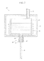
- the casting furnace 20 is a furnace which stores the molten copper transported from the holding furnace 13. As shown in FIG. 2 , the casting furnace 20 includes a chamber 21, a furnace main body 23, and a heating means (heating device) 24. An inert gas atmosphere is provided in the interior of the chamber 21. The heating means 24 is provided so as to adjust the temperature of the stored molten copper, and in the present embodiment, a radiation heater is provided. In addition, a pouring hole 26 is drilled in the bottom surface portions of the furnace main body 23 and the chamber 21.
- an area Sf of a cross-section along a horizontal direction of the inner portion of the furnace main body 23 in which the molten copper is stored is set to be in a range of 20000 mm 2 ⁇ Sf ⁇ 34600 mm 2 .
- a level sensor (not shown) is disposed for detecting the surface position of the molten copper which is stored in the inner portion of the furnace main body 23.
- the casting die 30 has a cylindrical shape including a casting hole 36 which penetrates the casting die 30 in an axial direction.
- the casting die 30 includes a graphite sleeve 31 which is provided in the inner circumferential surface of the casting hole 36 and a cooling jacket 32 which is positioned in the outer circumference side of the graphite sleeve 31.
- a water channel 33 for flowing cooling water is provided so as to cool the graphite sleeve 31.
- the casting die 30 is connected to the lower side of the casting furnace 20 in the vertical direction, and as shown in FIGS.
- the casting die 30 is disposed so that the pouring hole 26 of the casting furnace 20 communicate with the casting hole 36 of the casting die 30.
- the diameter of the casting hole 36 of the casting die 30 is set to be in a range of 50 mm or less, and preferably in a range of 10 mm or more to 40 mm or less. In the present embodiment, the diameter of the casting hole 36 is set to 30 mm.
- a cross-sectional area ratio Sf/Sc between a cross-sectional area Sc in a horizontal direction of the casting die 30 and the cross-sectional area Sf in the horizontal direction of the casting furnace 20 is set to be in a range of 5 or more (Sf/Sc ⁇ 5).
- the cross-sectional area ratio Sf/Sc is preferably in a range of 10 or more (Sf/Sc ⁇ 10).
- a heat insulation member 40 is disposed between the graphite sleeve 31 of the casting die 30 and the furnace main body 23 of the casting furnace 20.
- the heat insulation member 40 is disposed between the outside of a bottom surface of the chamber 21 and the outside of a bottom surface of the furnace main body 23.
- the heat insulation member 40 has a cylindrical shape including a through hole 46, and the inner circumferential surface of the through hole 46 is disposed so as to communicate with (extend to) the inner circumferential surface of the casting hole 36 of the casting die 30 and the inner circumferential surface of the pouring hole 26 of the casting furnace 20.
- the heat insulation member 40 is formed of ceramics such as Al 2 O 3 , SiO 2 , or the like, the thermal conductivity of the heat insulation member is in a range of 40 W/ (m ⁇ K) or less at room temperature, and the thickness thereof is set to be in a range of 5 mm or more to 60 mm or less.
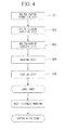
- the method for producing the copper alloy wire material containing an active element includes a molten-copper formation step S01 of melting a raw copper material so as to form the molten copper, an active-element addition step S02 of adding the active element to the obtained molten copper, a molten-copper transport step S03 of transporting the molten copper from the holding furnace 13 to the casting furnace 20, a holding step S04 of holding the molten copper, to which the active element is added, in the casting furnace 20, and a casting step S05 of producing the ingot W continuously by the casting die 30 connected to the casting furnace 20.
- a cathode of pure copper (4NCu) having a purity of 99.99 mass% or more to less than 99.999 mass% is prepared as the raw copper material.
- the 4NCu cathode is charged from the raw material charging port 11A to the melting furnace 11, and the 4NCu cathode is heated and molten in the melting furnace 11 to produce a molten copper. Then, the obtained molten copper is supplied from the molten copper discharging port 11B to the holding furnace 13 through the connection trough 12.
- the temperature of the molten copper is controlled to be in a range of, for example, 1100 to 1400°C by the heating means (heating device) (not shown) such as a heater or an induction heating coil.
- the active element such as Cr, Zr, Si, or the like is added to the molten copper in the holding furnace 13 so as to adjust components of the molten copper.
- an inert gas atmosphere is provided in the interior of the holding furnace 13 so as to suppress oxidation of the active element such as Cr, Zr, Si, or the like.
- the temperature of the molten copper is controlled to be in a range of, for example, 1100 to 1400°C by the heating means (heating device) 24 such as a radiation heater.
- the heating means (heating device) 24 such as a radiation heater.
- the surface position of the molten copper which is stored in the furnace main body 23 of the casting furnace 20 is detected by the level sensor, and the transport amount of the molten copper from the holding furnace 13 is adjusted such that the surface of the molten copper becomes constant.
- the molten copper which is stored in the casting furnace 20 is supplied into the casting hole 36 of the casting die 30 through the pouring hole 26.
- the molten copper supplied into the casting die 30 is solidified at the graphite sleeve 31 which is cooled by the cooling jacket 32, and the ingot W is produced from the lower end side of the casting hole 36.
- the withdrawing rate of the ingot W is controlled by the pinch rolls 17, and in the present embodiment, the apparatus is configured such that the ingot W is intermittently withdrawn.
- the withdrawing rate of the ingot W is adjusted to be in a range of 200 mm/min or more to 600 mm/min or less.
- the supply rate of the molten copper to the casting furnace 20 is adjusted to be in a range of 0.5 t/hour or more to 10 t/hour or less.
- a hydraulic head pressure of the molten copper stored in the furnace main body 23 of the casting furnace 20 acts on the interior of the casting die 30.
- the surface height of the molten copper in the furnace main body 23 is controlled such that the hydraulic head of the molten copper in the furnace main body 23 from an upper end 30a of the casting die 30 becomes in a range of 100 mm or more.
- the temperature of an upper end portion 3 1 a of the graphite sleeve 31 of the casting die 30 is set to be in a range of 450°C or less, and the temperature of the molten copper at a portion of the heat insulation member 40 is set to be higher than the melting point of the molten copper.
- the ingot W obtained in this way is cooled by a cooling means (not shown) and is coiled in a coil shape.
- a cooling means not shown
- a long ingot W having a temperature of 950°C or more is cooled to room temperature at a cooling rate of 50°C/min or more; and thereby, the ingot W is subjected to solution heat treatment.
- the ingot W which is cooled to room temperature is subjected to heat treatment, cold working, or the like; and thereby, the copper alloy wire material containing an active element having predetermined characteristics is produced.
- the insulation member 40 is disposed between the graphite sleeve 31 of the casting die 30 and the furnace main body 23 of the casting furnace 20. Therefore, the molten copper in the furnace main body 23 is prevented from directly contacting the graphite sleeve 31 of the casting die 30. Thereby, the reaction between the graphite sleeve 31 and the active element such as Cr, Zr, Si, or the like can be suppressed. As a result, fixing of the ingot W to the graphite sleeve 31 can be prevented; and thereby, deterioration of the graphite sleeve 31 can be prevented. Moreover, wear of the graphite sleeve 31 due to oxidation is suppressed; and thereby, the casting can be stably performed for a long time.
- the casting die 30 is disposed at the lower side of the casting furnace 20 in the vertical direction. Therefore, in the casting step S05, the molten copper can be cooled and solidified in the casting die 30 while the hydraulic head pressure of the molten copper held in the furnace main body 23 of the casting furnace 20 is applied to the interior of the casting die 30. Thereby, the molten copper can be securely supplied into the casting hole 36 of the casting die 30 even though the heat insulation member 40 is interposed; and as a result, the casting can be stably performed.
- the hydraulic head of the molten copper in the furnace main body 23 from the upper end of the casting die 30 is set to be in a range of 100 mm or more. Therefore, the molten copper can be securely supplied toward the inside of the casting die 30; and thereby, the casting can be stably performed. Moreover, occurrence of micro pores can be suppressed; and thereby, the ingot W having high quality can be produced.
- the temperature of the upper end portion 3 1 a of the graphite sleeve 31 of the casting die 30 is held in a range of 450°C or less, premature wear of the graphite sleeve 31 can be suppressed, and the reaction between the graphite sleeve and the active element such as Cr, Zr, Si, or the like can be suppressed.
- the graphite sleeve 31 of the casting die 30 and the furnace main body 23 of the casting furnace 20 are connected to each other through the heat insulation member 40. Therefore, even though the casting die 30 is cooled such that the temperature of the casting die 30 becomes in a range of 450°C or less, a decrease in the temperature of the molten copper in the casting furnace 20 can be prevented.
- the temperature of the molten copper at a portion of the heat insulation member 40 is set to be higher than the melting point of the molten copper, fluidity of the molten copper at a portion of the heat insulation member 40 is maintained; and thereby, the molten copper can be securely supplied into the casting die 30 by the hydraulic head pressure of the molten copper in the casting furnace 20.
- the casting die 30 and the casting furnace 20 are connected to each other through the heat insulation member 40. Therefore, even though the temperature of the molten copper at a portion of the heat insulation member 40 is set to be higher than the melting point of the molten copper, the casting die 30 is not exposed to a high temperature.
- the thermal conductivity of the heat insulation member 40 is set to be in a range of 40 W/(m ⁇ K) or less at room temperature and the thickness of the heat insulation member 40 is set to be in a range of 5 mm or more to 60 mm or less. Therefore, heat transfer between the graphite sleeve 31 of the casting die 30 and the furnace main body 23 of the casting furnace 20 can be securely suppressed.
- the cross-sectional area ratio Sf/Sc between a cross-sectional area Sc in the horizontal direction of the casting hole 36 of the casting die 30 and the cross-sectional area Sf in the horizontal direction of the casting furnace 20 is set to fulfill Sf/Sc ⁇ 5, and preferably Sf/Sc ⁇ 10. Therefore, in the casting step S05, the change in the surface of the molten copper in the furnace main body 23 can be suppressed to be kept low; and thereby, the hydraulic head pressure of the molten copper becomes stable. As a result, the ingot W having high quality can be produced.
- the melting furnace 11, the holding furnace 13, and the connection trough 12 are provided, and the molten copper formed in the molten-copper formation step S01 is continuously supplied into the casting furnace 20. Therefore, the ingot W can be effectively produced.
- an inert gas atmosphere is provided in the interiors of the melting furnace 11, the holding furnace 13, the transport trough 15, and the casting furnace 20, oxidation of the molten copper and the active element such as Cr, Zr, Si, or the like can be prevented; and thereby, the ingot W having high quality can be produced.
- the present invention is not limited thereto.
- the invention can be appropriately modified within a scope which does not depart from the technical features of the present invention.
- the solution heat treatment is performed by rapidly cooling the obtained ingot W.
- the present invention is not limited thereto.
- the ingot W is cooled, and then, the solution heat treatment may be performed.
- the solution heat treatment itself may not be performed.
- the present embodiment is described by using the continuous casting apparatus 10 including the melting furnace 11, the holding furnace 13, and the connection trough 12.
- the present invention is not limited thereto.
- the molten copper may be formed by a batch type melting furnace 111, and the molten copper may be supplied to the casting furnace 20 through the transport trough 15.
- the component adjustment may be performed in the batch type melting furnace 111. That is, the molten-copper formation step S01 and the active-element addition step S02 may be simultaneously performed.
- a plurality of batch type melting furnaces 111 may be connected to the casting furnace 20, the molten copper may be alternately supplied to the casting furnace 20 from the batch type melting furnaces 111. Thereby, a long ingot W may be produced.
- the case of producing the copper alloy wire material of the Cu-Cr-Zr-Si alloy is described, and the Cu-Cr-Zr-Si alloy includes Cr: 0.25 mass% or more to 0.45 mass% or less, Zr: 0.05 mass% or more to 0.15 mass% or less, and Si: 0.01 mass% or more to 0.05 mass% or less, with the balance including Cu and inevitable impurities.
- the copper alloy wire material may contain one or more active elements selected from Cr, Zr, and Si, and the copper alloy wire material may contain other elements.
- the case where the diameter of the casting hole 36 of the casting die 30 is in a range of 50 mm or less and is preferably in a range of 10 mm or more to 40 mm or less is described.
- the present invention is not limited thereto.
- the withdrawing rate of the ingot W or the supply rate of the molten copper to the casting furnace 20 in the casting step is not limited to the values described in the present embodiment.
- the case where only one pouring hole 26 and only one casting hole 36 are provided is shown and described.
- the present invention is not limited thereto.
- a plurality of pouring holes 26 and casting holes 36 may be provided, and a plurality of ingots W may be simultaneously produced.
- the case where the ingot W is intermittently withdrawn is described.
- the present invention is not limited thereto.
- the ingot W may be continuously withdrawn.
- the present invention is not limited thereto.
- the interiors thereof may be maintained in a vacuum (decompression) state so as to prevent oxidation of the molten copper and the active metal.
- the casting die 30 includes the graphite sleeve 31 is described.
- the present invention is not limited thereto.
- the casting die 30 may be formed of other materials having solid lubrication property such as boron nitride (BN) or the like.
- the inner circumferential surface of the through hole 46 of the heat insulation member 40 communicates with (extends to) the inner circumferential surface of the casting hole 36 of the casting die 30 is described.
- the present invention is not limited thereto.
- the inner circumferential surface of the through hole 46 may be retracted further outward in the diameter direction than the inner circumferential surface of the casting hole 36. That is, the diameter of the through hole 46 may be greater than the diameter of the casting hole 36.
- the constituent members of the casting die 30 are not limited to those described in the present embodiment.
- the structure of the cooling jacket 32, the disposition of the water-cooling piping (water channel 33), or the like may be appropriately changed.
- the copper alloy wire material which consists of the copper alloy containing the active metal can be effectively and stably produced. Since the copper alloy wire material containing the active metal has a high strength and an excellent electrical conduction property, the copper alloy wire material can be used in, for example, trolley wires of high-speed railways or the like. An aspect of the present invention can be appropriately applied to the method for producing the copper alloy wire material.
- W ingot
- 11 melting furnace
- 13 holding furnace
- 20 casting furnace
- 30 casting die
- 30a upper end of casting die
- 40 heat insulation member
- S01 molten-copper formation step
- S02 active-element addition step
- S04 holding step
- S05 casting step.
Landscapes
- Engineering & Computer Science (AREA)
- Mechanical Engineering (AREA)
- Chemical & Material Sciences (AREA)
- Materials Engineering (AREA)
- Metallurgy (AREA)
- Organic Chemistry (AREA)
- Continuous Casting (AREA)
Abstract
Description
- The present invention relates to a method for producing a copper alloy wire having a high strength which consists of a copper alloy containing Cr, Zr, Si, or the like and is used in a trolley wire for an electric train, or the like.
The present application claims priority on Japanese Patent Application No.2010-14397 filed on January 26, 2010 - Conventionally, as a material of a trolley wire for an electric train or the like, copper wire materials such as pure copper, a copper alloy containing Sn, and the like are widely used. For example, these copper wire materials are produced using continuous casting machines disclosed in Patent Document 1 and Patent Document 2. In the continuous machines disclosed in Patent Document 1 and Patent Document 2, a casting die is directly connected to a casting furnace, and an ingot which is obtained by being solidified in the casting die is withdrawn toward a horizontal direction, upward in a vertical direction, or downward in a vertical direction.
Since an ingot having a relatively small diameter can be produced continuously by such continuous casting machines, the continuous casting machines are particularly suitable for producing wires. - In recent years, as a trolley wire for a high-speed railway such as bullet trains and the like, a wire material is required which consists of a copper alloy having a higher strength than that of a conventional material and an improved electrical conduction property.
Here, as the copper alloy having a higher strength and an improved electrical conduction property, for example, there is a copper alloy which contains Cr, Zr, Si, or the like. With regard to the copper alloy which contains the elements, precipitate particles are dispersed in a parent phase (matrix) of copper by conducting a suitable heat treatment; and thereby, the strength can be improved, and the electrical conduction property can be secured. - Conventionally, the wire material of the copper alloy containing Cr, Zr, Si, or the like is produced as follows. An ingot having a large cross-sectional area which is referred to as a cake or a billet is produced, and then the ingot is subjected to hot working or cold working.
However, in the case where the ingot having a large cross-sectional area is produced, and then the ingot is subjected to hot working or cold working to produce the wire material, a length of the wire material is limited depending on the size of the ingot; and therefore, a long wire material cannot be obtained. Moreover, there is a problem in that production efficiency is low. - Thus, Patent Document 3 discloses a technological thought in which a wire material of a copper alloy containing Cr, Zr, or the like is withdrawn toward a horizontal direction, upward in a vertical direction, or downward in a vertical direction so as to continuously produce the wire material having a small diameter. That is, a technological thought is proposed in which the wire material of the copper alloy containing Cr, Zr, or the like is casted by the continuous casting machines shown in Patent Document 1 and Patent Document 2.
In addition, Patent Document 4 discloses a technology in which a wire material of a copper alloy containing Cr, Zr, or the like is produced by a horizontal continuous casting machine using a heated casting die. - However, in the continuous casting machines disclosed in Patent Document 1 and Patent Document 2, a casting die generally consists of graphite which is excellent in solid lubrication property, and the casting die consisting of graphite directly contacts a molten metal in the casting furnace.
Here, the elements such as Cr, Zr, Si and the like are active elements having high reactivity with the graphite. Therefore, the casting die react with the elements (active elements) such as Cr, Zr, Si and the like in the molten copper to generate carbides. Thereby, the casted ingot is fixed to the casting die, or the casting die is worn rapidly. As a result, the casting cannot be stably performed for a long time. - In the horizontal continuous casting machines disclosed in Patent Document 1 and Patent Document 2, the ingot is withdrawn in a substantially horizontal direction; and therefore, the ingot is affected by gravity at the time of being solidified in the casting die. Moreover, a gap referred to as an air gap is generated between the casting die and the ingot due to solidification shrinkage. In the horizontal continuous casting machines, the amount of air gap at the upper side of the ingot becomes different from the amount of air gap at the lower side of the ingot. Therefore, the cooling speed at the upper side of the ingot becomes different from the cooling speed at the lower side of the ingot. As a result, there is a concern that quality of the ingot consisting of the copper alloy containing Cr, Zr, Si, or the like may not be stable. In addition, as described above, the ingot is fixed to the casting die or the casting die is worn rapidly; and therefore, surface quality of the ingot is deteriorated or it becomes difficult to withdraw the ingot from the casting die. As a result, it is difficult to stably perform the casting.
- Patent Document 3 discloses a technological thought in which a wire material of a copper alloy containing Cr, Zr, or the like is withdrawn toward a horizontal direction, upward in a vertical direction, or downward in a vertical direction so as to continuously produce the wire material having a small diameter. However, as described above, in the conventional continuous casting method, the wire material of the copper alloy containing Cr, Zr, Si, or the like cannot be continuously produced.
- In addition, Patent Document 4 discloses that the heated casting die is used so as to suppress the reaction between the graphite and the active elements such as Cr, Zr, or the like, and the wire material of the copper alloy containing Cr, Zr, or the like is continuously produced by the horizontal continuous casting machine. However, the graphite casting die itself contacts the molten copper having a high temperature; and therefore, wear due to oxidation becomes severe. Moreover, in the case where the heated casting die is used, it is difficult to increase the withdrawing rate of the ingot; and therefore, there is a problem in that the production efficiency cannot be improved. In addition, in Patent Document 4, the ingot is withdrawn in a substantially horizontal direction; and therefore, the ingot is also affected by gravity. As a result, there is a problem in that the quality is not stable.
-
- Patent Document 1: Japanese Unexamined Patent Application, First Publication No.
H06-226406 - Patent Document 2: Japanese Unexamined Patent Application, First Publication No.
S61-209757 - Patent Document 3: Japanese Unexamined Patent Application, First Publication No.
2006-138015 - Patent Document 4: Japanese Examined Patent Application, Second Publication No.
H08-000956 - The present invention is made with consideration of the above-described problems, and an object thereof is to provide a method for producing a copper alloy wire material containing an active element which is capable of efficiently and stably producing the copper alloy wire material consisting of a copper alloy containing an active metal such as Cr, Zr, Si, or the like.
- In order to solve the above-described problems and achieve the object, an aspect of the present invention includes the following features.
A method for producing a copper alloy wire material containing an active element according to an aspect of the present invention includes: a molten-copper formation step of melting a raw copper material so as to form a molten copper; an active-element addition step of adding an active element to the molten copper; a holding step of holding the molten copper in a casting furnace; and a casting step of producing an ingot continuously by a casting die connected to the casting furnace, wherein the casting die is connected to a lower side of the casting furnace in a vertical direction through a heat insulation member, and in the casting step, a pressure is applied toward the inside of the casting die so as to supply the molten copper into the casting die, and the molten copper is cooled and solidified in the casting die.
The copper alloy wire material containing an active element consists of a copper alloy containing an active element.
In the method for producing a copper alloy wire material containing an active element according to the aspect of the invention, a temperature of the casting die may be held within a range of 450°C or less.
A temperature of the molten copper at a portion of the heat insulation member may be set to be higher than a melting point of the molten copper.
In the casting step, a hydraulic head of the molten copper in the casting furnace from an upper end of the casting die may be in a range of 100 mm or more.
A cross-sectional area ratio Sf/Sc between a cross-sectional area Sc in a horizontal direction of the casting die and a cross-sectional area Sf in a horizontal direction of the casting furnace may be in a range of 5 or more.
A continuous melt furnace and a holding furnace may be provided at a former stage prior to the casting furnace, and the molten copper formed in the molten-copper formation step may be continuously supplied into the casting furnace. - In the method for producing the copper alloy wire material containing an active element according to the aspect of the present invention, since the heat insulation member is disposed between the casting die and the casting furnace, the casting die is prevented from being heated up to the same temperature as that of the molten copper in the inner portion of the casting furnace. Thereby, reaction between the casting die and the active element such as Cr, Zr, Si or the like can be suppressed. Moreover, even though the temperature of the casting die is kept to be low, the temperature of the molten copper in the casting furnace at or in the vicinity of the casting die is maintained to be high; and as a result, the casting can be stably performed.
- In addition, in the casting step, a pressure is applied toward the inside of the casting die so as to supply the molten copper into the casting die, and the molten copper is cooled and solidified in the casting die. Thereby, as described above, even though the heat insulation member is disposed between the casting furnace and the casting die, the molten copper can be securely supplied from the casting furnace to the casting die, and the casting can be stably performed. Moreover, since the casting die is disposed at a lower portion in the vertical direction of the casting furnace, the pressure can be securely applied to the inside of the casting die by utilizing the hydraulic head pressure of the molten copper which is held in the casting furnace.
- Here, it is preferable that the temperature of the casting die, that is, the temperature of the portion which has the highest temperature in the casting die be held within a range of 450°C or less.
In this case, the temperature of the portion which has the highest temperature in the casting die is held within a range of 450°C or less by cooling the casting die. Thereby, premature wear (rapid wear) of the casting die can be suppressed, and reaction between the casting die and the active element such as Cr, Zr, Si or the like can be suppressed. Particularly, in the case where a portion of the casting die is formed of graphite, wear of the casting die due to oxidation can be securely suppressed. Moreover, the casting die and the casting furnace are connected to each other through the heat insulation member. Therefore, even though the casting die is held at a temperature in a range of 450°C or less, a decrease in the temperature of the molten copper in the casting furnace can be prevented, and the casing can be stably performed. - It is preferable that the temperature of the molten copper at a portion of the heat insulation member be set to be higher than the melting point of the molten copper.
In this case, fluidity of the molten copper at a portion of the heat insulation member is maintained; and thereby, the molten copper can be securely supplied into the casting die by the hydraulic head pressure of the molten copper in the casting furnace. Moreover, the casting die and the casting furnace are connected to each other through the heat insulation member. Therefore, even though the temperature of the molten copper passing through the inside of the heat insulation member is set to be higher than the melting point of the molten copper, the casting die is not exposed to a high temperature. As a result, premature wear of the casting die or the reaction between the casting die and the active element can be suppressed. - It is preferable that, in the casting step, the hydraulic head of the molten copper in the casting furnace from the upper end of the casting die be in a range of 100 mm or more.
In this case, the molten copper can be securely supplied toward the inside of the casting die, and the casting can be stably performed. Moreover, occurrence of micro pores can be suppressed; and thereby, the ingot having high quality can be produced. - It is preferable that the cross-sectional area ratio Sf/Sc between the cross-sectional area Sc in the horizontal direction of the casting die and the cross-sectional area Sf in the horizontal direction of the casting furnace be in a range of 5 or more.
In this case, change in the surface of the molten copper in the casting furnace can be suppressed to be kept low when the ingot is withdrawn from the casting die. Accordingly, the hydraulic head pressure of the molten copper becomes stable; and thereby, the ingot having high quality can be produced. - It is preferable that the continuous melt furnace and the holding furnace be provided at a former stage prior to the casting furnace, and the molten copper formed in the molten-copper formation step be continuously supplied into the casting furnace.
In this case, since the molten copper is continuously supplied into the casting furnace, a long ingot can be produced. Moreover, the ingot which is utilized as a raw material of the wire material can be effectively produced. - According to the aspect of the present invention, the copper alloy wire material which consists of the copper alloy containing the active metal such as Cr, Zr, Si, or the like can be effectively and stably produced.
-
-
FIG. 1 is a schematic explanatory diagram showing an example of a continuous casting apparatus which is used in an embodiment of a method for producing a copper alloy wire material containing an active element according to an aspect of the present invention. -
FIG. 2 is an explanatory diagram of a casting furnace which is included in the continuous casting apparatus shown inFIG. 1 . -
FIG. 3 is an enlarged explanatory diagram of a connection portion between the casting furnace and the casting die. -
FIG. 4 is a flow diagram of the embodiment of the method for producing the copper alloy wire material containing an active element according to an aspect of the present invention. -
FIG. 5 is a schematic explanatory diagram showing another example of the continuous casting apparatus which is used in the embodiment of a method for producing the copper alloy wire material containing an active element according to an aspect of the present invention. - Hereinafter, an embodiment of a method for producing a copper alloy wire material containing an active element according to an aspect of the present invention will be described with reference to the accompanying drawings.
The copper alloy wire material containing an active element which is produced by the producing process of the present embodiment includes Cr, Zr, Si, or the like which is an active element having high reactivity with graphite which configures agraphite sleeve 31 described below. Here, the element having high reactivity with the graphite is an element which has a low standard formation free energy of carbide and which is more stable in a state of carbide than in a state of a single element alone. - In the present embodiment, the copper alloy wire material containing an active element consists of a Cu-Cr-Zr-Si alloy which includes Cr: 0.25 mass% or more to 0.45 mass% or less, Zr: 0.05 mass% or more to 0.15 mass% or less, and Si: 0.01 mass% or more to 0.05 mass% or less, with the balance including Cu and inevitable impurities.
In addition, a wire diameter (diameter) of the copper alloy wire material containing an active element is in a range of 10 mm or more to 40 mm or less, and the diameter is 30 mm in the present embodiment. - Next, a continuous casting apparatus which is used in the method for producing the copper alloy wire material containing an active element of the present embodiment will be described.
FIG. 1 shows acontinuous casting apparatus 10 for producing an ingot W which is utilized as a raw material of the copper alloy wire material containing an active element.
Thecontinuous casting apparatus 10 includes a meltingfurnace 11, a holdingfurnace 13, atransport trough 15, a castingfurnace 20, acasting die 30, and pinch rolls 17 for withdrawing the produced ingot W. - The melting
furnace 11 is a furnace which heats and melts a raw copper material to produce a molten copper, and the meltingfurnace 11 includes a rawmaterial charging port 11A to which the raw copper material is charged and a moltencopper discharging port 11B from which the produced molten copper is discharged.
Moreover, the holdingfurnace 13 is disposed at the subsequent stage side of the meltingfurnace 11, and the meltingfurnace 11 and the holdingfurnace 13 are connected to each other by aconnection trough 12. - The holding
furnace 13 is a furnace which temporarily holds the molten copper supplied from the meltingfurnace 11 and keeps the molten copper hot. A feeding means (feeding device) (not shown) for adding the active element such as Cr, Zr, Si, or the like is provided in the holdingfurnace 13. In addition, an inert gas atmosphere is provided in the interior of the holdingfurnace 13 in order to prevent oxidation of the active element. - The
transport trough 15 is a trough for transporting the molten copper to which the active element such as Cr, Zr, Si, or the like is added so as to adjust the components to the castingfurnace 20 disposed at the subsequent stage. In the present embodiment, an inert gas atmosphere is provided in the interior of thetransport trough 15. - The casting
furnace 20 is a furnace which stores the molten copper transported from the holdingfurnace 13. As shown inFIG. 2 , the castingfurnace 20 includes achamber 21, a furnacemain body 23, and a heating means (heating device) 24. An inert gas atmosphere is provided in the interior of thechamber 21. The heating means 24 is provided so as to adjust the temperature of the stored molten copper, and in the present embodiment, a radiation heater is provided. In addition, a pouringhole 26 is drilled in the bottom surface portions of the furnacemain body 23 and thechamber 21.
In the castingfurnace 20, an area Sf of a cross-section along a horizontal direction of the inner portion of the furnacemain body 23 in which the molten copper is stored is set to be in a range of 20000 mm2 ≤ Sf ≤ 34600 mm2. Moreover, in the castingfurnace 20, a level sensor (not shown) is disposed for detecting the surface position of the molten copper which is stored in the inner portion of the furnacemain body 23. - As shown in
FIG. 3 , the casting die 30 has a cylindrical shape including acasting hole 36 which penetrates the casting die 30 in an axial direction. The casting die 30 includes agraphite sleeve 31 which is provided in the inner circumferential surface of thecasting hole 36 and a coolingjacket 32 which is positioned in the outer circumference side of thegraphite sleeve 31. In the inner portion of the coolingjacket 32, awater channel 33 for flowing cooling water is provided so as to cool thegraphite sleeve 31.
The casting die 30 is connected to the lower side of the castingfurnace 20 in the vertical direction, and as shown inFIGS. 2 and3 , the casting die 30 is disposed so that the pouringhole 26 of the castingfurnace 20 communicate with thecasting hole 36 of the casting die 30. The diameter of thecasting hole 36 of the casting die 30 is set to be in a range of 50 mm or less, and preferably in a range of 10 mm or more to 40 mm or less. In the present embodiment, the diameter of thecasting hole 36 is set to 30 mm. - A cross-sectional area ratio Sf/Sc between a cross-sectional area Sc in a horizontal direction of the casting die 30 and the cross-sectional area Sf in the horizontal direction of the casting
furnace 20 is set to be in a range of 5 or more (Sf/Sc ≥ 5). The cross-sectional area ratio Sf/Sc is preferably in a range of 10 or more (Sf/Sc ≥ 10). - A
heat insulation member 40 is disposed between thegraphite sleeve 31 of the casting die 30 and the furnacemain body 23 of the castingfurnace 20. In the present embodiment, theheat insulation member 40 is disposed between the outside of a bottom surface of thechamber 21 and the outside of a bottom surface of the furnacemain body 23. Moreover, theheat insulation member 40 has a cylindrical shape including a throughhole 46, and the inner circumferential surface of the throughhole 46 is disposed so as to communicate with (extend to) the inner circumferential surface of thecasting hole 36 of the casting die 30 and the inner circumferential surface of the pouringhole 26 of the castingfurnace 20.
For example, theheat insulation member 40 is formed of ceramics such as Al2O3, SiO2, or the like, the thermal conductivity of the heat insulation member is in a range of 40 W/ (m·K) or less at room temperature, and the thickness thereof is set to be in a range of 5 mm or more to 60 mm or less. - Next, the method for producing the copper alloy containing an active element of the present embodiment using the above-described
continuous casting apparatus 10 will be described.
As shown inFIG. 4 , the method for producing the copper alloy wire material containing an active element includes a molten-copper formation step S01 of melting a raw copper material so as to form the molten copper, an active-element addition step S02 of adding the active element to the obtained molten copper, a molten-copper transport step S03 of transporting the molten copper from the holdingfurnace 13 to the castingfurnace 20, a holding step S04 of holding the molten copper, to which the active element is added, in the castingfurnace 20, and a casting step S05 of producing the ingot W continuously by the casting die 30 connected to the castingfurnace 20. - At first, a cathode of pure copper (4NCu) having a purity of 99.99 mass% or more to less than 99.999 mass% is prepared as the raw copper material. The 4NCu cathode is charged from the raw
material charging port 11A to the meltingfurnace 11, and the 4NCu cathode is heated and molten in themelting furnace 11 to produce a molten copper. Then, the obtained molten copper is supplied from the moltencopper discharging port 11B to the holdingfurnace 13 through theconnection trough 12. - In the holding
furnace 13, while the supplied molten copper is temporarily held, the temperature of the molten copper is controlled to be in a range of, for example, 1100 to 1400°C by the heating means (heating device) (not shown) such as a heater or an induction heating coil. In addition, the active element such as Cr, Zr, Si, or the like is added to the molten copper in the holdingfurnace 13 so as to adjust components of the molten copper. At this time, an inert gas atmosphere is provided in the interior of the holdingfurnace 13 so as to suppress oxidation of the active element such as Cr, Zr, Si, or the like. - The molten copper, to which the active element such as Cr, Zr, Si, or the like is added in the holding
furnace 13, is supplied to the castingfurnace 20 through thetransport trough 15. As described above, an inert gas atmosphere is provided in the interior of thetransport trough 15; and thereby, oxidation of the molten copper and the active element is prevented. - In the casting
furnace 20, while the molten copper, to which the active element such as Cr, Zr, Si, or the like is added, is held, the temperature of the molten copper is controlled to be in a range of, for example, 1100 to 1400°C by the heating means (heating device) 24 such as a radiation heater. Here, the surface position of the molten copper which is stored in the furnacemain body 23 of the castingfurnace 20 is detected by the level sensor, and the transport amount of the molten copper from the holdingfurnace 13 is adjusted such that the surface of the molten copper becomes constant. - Then, the molten copper which is stored in the casting
furnace 20 is supplied into thecasting hole 36 of the casting die 30 through the pouringhole 26. The molten copper supplied into the casting die 30 is solidified at thegraphite sleeve 31 which is cooled by the coolingjacket 32, and the ingot W is produced from the lower end side of thecasting hole 36. Here, the withdrawing rate of the ingot W is controlled by the pinch rolls 17, and in the present embodiment, the apparatus is configured such that the ingot W is intermittently withdrawn. - In the casting step 05, the withdrawing rate of the ingot W is adjusted to be in a range of 200 mm/min or more to 600 mm/min or less. Moreover, the supply rate of the molten copper to the casting
furnace 20 is adjusted to be in a range of 0.5 t/hour or more to 10 t/hour or less. - In addition, in the casting step S05, a hydraulic head pressure of the molten copper stored in the furnace
main body 23 of the castingfurnace 20 acts on the interior of the casting die 30. In the present embodiment, the surface height of the molten copper in the furnacemain body 23 is controlled such that the hydraulic head of the molten copper in the furnacemain body 23 from anupper end 30a of the casting die 30 becomes in a range of 100 mm or more.
Moreover, in the casting step S05, the temperature of an upper end portion 3 1 a of thegraphite sleeve 31 of the casting die 30 is set to be in a range of 450°C or less, and the temperature of the molten copper at a portion of theheat insulation member 40 is set to be higher than the melting point of the molten copper. - The ingot W obtained in this way is cooled by a cooling means (not shown) and is coiled in a coil shape. In the present embodiment, for example, a long ingot W having a temperature of 950°C or more is cooled to room temperature at a cooling rate of 50°C/min or more; and thereby, the ingot W is subjected to solution heat treatment.
Then, the ingot W which is cooled to room temperature is subjected to heat treatment, cold working, or the like; and thereby, the copper alloy wire material containing an active element having predetermined characteristics is produced. - According to the method for producing the copper alloy containing an active element of the present embodiment including the above-described steps, the
insulation member 40 is disposed between thegraphite sleeve 31 of the casting die 30 and the furnacemain body 23 of the castingfurnace 20. Therefore, the molten copper in the furnacemain body 23 is prevented from directly contacting thegraphite sleeve 31 of the casting die 30. Thereby, the reaction between thegraphite sleeve 31 and the active element such as Cr, Zr, Si, or the like can be suppressed. As a result, fixing of the ingot W to thegraphite sleeve 31 can be prevented; and thereby, deterioration of thegraphite sleeve 31 can be prevented. Moreover, wear of thegraphite sleeve 31 due to oxidation is suppressed; and thereby, the casting can be stably performed for a long time. - In addition, the casting die 30 is disposed at the lower side of the casting
furnace 20 in the vertical direction. Therefore, in the casting step S05, the molten copper can be cooled and solidified in the casting die 30 while the hydraulic head pressure of the molten copper held in the furnacemain body 23 of the castingfurnace 20 is applied to the interior of the casting die 30. Thereby, the molten copper can be securely supplied into thecasting hole 36 of the casting die 30 even though theheat insulation member 40 is interposed; and as a result, the casting can be stably performed. Particularly, in the present embodiment, in the casting step S05, the hydraulic head of the molten copper in the furnacemain body 23 from the upper end of the casting die 30 is set to be in a range of 100 mm or more. Therefore, the molten copper can be securely supplied toward the inside of the casting die 30; and thereby, the casting can be stably performed. Moreover, occurrence of micro pores can be suppressed; and thereby, the ingot W having high quality can be produced. - Since the temperature of the upper end portion 3 1 a of the
graphite sleeve 31 of the casting die 30 is held in a range of 450°C or less, premature wear of thegraphite sleeve 31 can be suppressed, and the reaction between the graphite sleeve and the active element such as Cr, Zr, Si, or the like can be suppressed. Moreover, thegraphite sleeve 31 of the casting die 30 and the furnacemain body 23 of the castingfurnace 20 are connected to each other through theheat insulation member 40. Therefore, even though the casting die 30 is cooled such that the temperature of the casting die 30 becomes in a range of 450°C or less, a decrease in the temperature of the molten copper in the castingfurnace 20 can be prevented. - In addition, since the temperature of the molten copper at a portion of the
heat insulation member 40 is set to be higher than the melting point of the molten copper, fluidity of the molten copper at a portion of theheat insulation member 40 is maintained; and thereby, the molten copper can be securely supplied into the casting die 30 by the hydraulic head pressure of the molten copper in the castingfurnace 20. Moreover, the casting die 30 and the castingfurnace 20 are connected to each other through theheat insulation member 40. Therefore, even though the temperature of the molten copper at a portion of theheat insulation member 40 is set to be higher than the melting point of the molten copper, the casting die 30 is not exposed to a high temperature. As a result, premature wear of the casting die 30 or the reaction between the casting die and the active element can be suppressed.
Particularly, in the present embodiment, the thermal conductivity of theheat insulation member 40 is set to be in a range of 40 W/(m·K) or less at room temperature and the thickness of theheat insulation member 40 is set to be in a range of 5 mm or more to 60 mm or less. Therefore, heat transfer between thegraphite sleeve 31 of the casting die 30 and the furnacemain body 23 of the castingfurnace 20 can be securely suppressed. - The cross-sectional area ratio Sf/Sc between a cross-sectional area Sc in the horizontal direction of the
casting hole 36 of the casting die 30 and the cross-sectional area Sf in the horizontal direction of the castingfurnace 20 is set to fulfill Sf/Sc ≥ 5, and preferably Sf/Sc ≥ 10. Therefore, in the casting step S05, the change in the surface of the molten copper in the furnacemain body 23 can be suppressed to be kept low; and thereby, the hydraulic head pressure of the molten copper becomes stable. As a result, the ingot W having high quality can be produced. - Moreover, in the former stage prior to the casting
furnace 20, the meltingfurnace 11, the holdingfurnace 13, and theconnection trough 12 are provided, and the molten copper formed in the molten-copper formation step S01 is continuously supplied into the castingfurnace 20. Therefore, the ingot W can be effectively produced.
In the present embodiment, since an inert gas atmosphere is provided in the interiors of the meltingfurnace 11, the holdingfurnace 13, thetransport trough 15, and the castingfurnace 20, oxidation of the molten copper and the active element such as Cr, Zr, Si, or the like can be prevented; and thereby, the ingot W having high quality can be produced. - As described above, the embodiment of the present invention is described. However, the present invention is not limited thereto. The invention can be appropriately modified within a scope which does not depart from the technical features of the present invention.
For example, in the present embodiment, the case where the solution heat treatment is performed by rapidly cooling the obtained ingot W is described. However, the present invention is not limited thereto. For example, the ingot W is cooled, and then, the solution heat treatment may be performed. Alternatively, the solution heat treatment itself may not be performed. - The present embodiment is described by using the
continuous casting apparatus 10 including the meltingfurnace 11, the holdingfurnace 13, and theconnection trough 12. However, the present invention is not limited thereto. For example, as shown inFIG. 5 , the molten copper may be formed by a batchtype melting furnace 111, and the molten copper may be supplied to the castingfurnace 20 through thetransport trough 15. In this case, the component adjustment may be performed in the batchtype melting furnace 111. That is, the molten-copper formation step S01 and the active-element addition step S02 may be simultaneously performed. Moreover, a plurality of batchtype melting furnaces 111 may be connected to the castingfurnace 20, the molten copper may be alternately supplied to the castingfurnace 20 from the batchtype melting furnaces 111. Thereby, a long ingot W may be produced. - In the present embodiment, the case of producing the copper alloy wire material of the Cu-Cr-Zr-Si alloy is described, and the Cu-Cr-Zr-Si alloy includes Cr: 0.25 mass% or more to 0.45 mass% or less, Zr: 0.05 mass% or more to 0.15 mass% or less, and Si: 0.01 mass% or more to 0.05 mass% or less, with the balance including Cu and inevitable impurities. However, the present invention is not limited thereto. For example, the copper alloy wire material may contain one or more active elements selected from Cr, Zr, and Si, and the copper alloy wire material may contain other elements.
The case where the diameter of thecasting hole 36 of the casting die 30 is in a range of 50 mm or less and is preferably in a range of 10 mm or more to 40 mm or less is described. However, the present invention is not limited thereto. - The withdrawing rate of the ingot W or the supply rate of the molten copper to the casting
furnace 20 in the casting step is not limited to the values described in the present embodiment.
The case where only one pouringhole 26 and only onecasting hole 36 are provided is shown and described. However, the present invention is not limited thereto. For example, a plurality of pouringholes 26 and castingholes 36 may be provided, and a plurality of ingots W may be simultaneously produced.
The case where the ingot W is intermittently withdrawn is described. However, the present invention is not limited thereto. For example, the ingot W may be continuously withdrawn. - The case where an inert gas atmosphere is provided in the interiors of the melting
furnace 11, the holdingfurnace 13, thetransport trough 15, and the castingfurnace 20 is described. However, the present invention is not limited thereto. For example, the interiors thereof may be maintained in a vacuum (decompression) state so as to prevent oxidation of the molten copper and the active metal.
The case where the casting die 30 includes thegraphite sleeve 31 is described. However, the present invention is not limited thereto. For example, the casting die 30 may be formed of other materials having solid lubrication property such as boron nitride (BN) or the like. - The case where the inner circumferential surface of the through
hole 46 of theheat insulation member 40 communicates with (extends to) the inner circumferential surface of thecasting hole 36 of the casting die 30 is described. However, the present invention is not limited thereto. For example, the inner circumferential surface of the throughhole 46 may be retracted further outward in the diameter direction than the inner circumferential surface of thecasting hole 36. That is, the diameter of the throughhole 46 may be greater than the diameter of thecasting hole 36.
The constituent members of the casting die 30 are not limited to those described in the present embodiment. For example, the structure of the coolingjacket 32, the disposition of the water-cooling piping (water channel 33), or the like may be appropriately changed. - According to an aspect of the present invention, the copper alloy wire material which consists of the copper alloy containing the active metal can be effectively and stably produced. Since the copper alloy wire material containing the active metal has a high strength and an excellent electrical conduction property, the copper alloy wire material can be used in, for example, trolley wires of high-speed railways or the like. An aspect of the present invention can be appropriately applied to the method for producing the copper alloy wire material.
- W: ingot, 11: melting furnace, 13: holding furnace, 20: casting furnace, 30: casting die, 30a: upper end of casting die, 40: heat insulation member, S01: molten-copper formation step, S02: active-element addition step, S04: holding step, and S05: casting step.
Claims (6)
- A method for producing a copper alloy wire material containing an active element comprising:a molten-copper formation step of melting a raw copper material so as to form a molten copper;an active-element addition step of adding an active element to the molten copper;a holding step of holding the molten copper in a casting furnace; anda casting step of producing an ingot continuously by a casting die connected to the casting furnace,wherein the casting die is connected to a lower side of the casting furnace in a vertical direction through a heat insulation member, andin the casting step, a pressure is applied toward the inside of the casting die so as to supply the molten copper into the casting die, and the molten copper is cooled and solidified in the casting die.
- The method for producing a copper alloy wire material containing an active element according to claim 1,
wherein a temperature of the casting die is held within a range of 450°C or less. - The method for producing a copper alloy wire material containing an active element according to claim 1 or 2,
wherein a temperature of the molten copper at a portion of the heat insulation member is set to be higher than a melting point of the molten copper. - The method for producing a copper alloy wire material containing an active element according to any one of claims 1 to 3,
wherein, in the casting step, a hydraulic head of the molten copper in the casting furnace from an upper end of the casting die is in a range of 100 mm or more. - The method for producing a copper alloy wire material containing an active element according to any one of claims I to 4,
wherein a cross-sectional area ratio Sf/Sc between a cross-sectional area Sc in a horizontal direction of the casting die and a cross-sectional area Sf in a horizontal direction of the casting furnace is in a range of 5 or more. - The method for producing a copper alloy wire material containing an active element according to any one of claims 1 to 5,
wherein a continuous melt furnace and a holding furnace are provided at a former stage prior to the casting furnace, and the molten copper formed in the molten-copper formation step is continuously supplied into the casting furnace.
Applications Claiming Priority (2)
| Application Number | Priority Date | Filing Date | Title |
|---|---|---|---|
| JP2010014397 | 2010-01-26 | ||
| PCT/JP2011/051433 WO2011093310A1 (en) | 2010-01-26 | 2011-01-26 | Process for producing copper alloy wire containing active element |
Publications (2)
| Publication Number | Publication Date |
|---|---|
| EP2529860A1 true EP2529860A1 (en) | 2012-12-05 |
| EP2529860A4 EP2529860A4 (en) | 2017-02-22 |
Family
ID=44319296
Family Applications (1)
| Application Number | Title | Priority Date | Filing Date |
|---|---|---|---|
| EP11737023.9A Withdrawn EP2529860A4 (en) | 2010-01-26 | 2011-01-26 | Process for producing copper alloy wire containing active element |
Country Status (5)
| Country | Link |
|---|---|
| EP (1) | EP2529860A4 (en) |
| JP (1) | JP5613907B2 (en) |
| CN (1) | CN102686337B (en) |
| TW (1) | TWI520799B (en) |
| WO (1) | WO2011093310A1 (en) |
Cited By (2)
| Publication number | Priority date | Publication date | Assignee | Title |
|---|---|---|---|---|
| WO2014001848A1 (en) | 2012-06-29 | 2014-01-03 | Le Bronze Industriel | Crucible for a machine for continuously casting a bar or a coil of a metal alloy |
| EP3243919A4 (en) * | 2015-01-07 | 2018-07-04 | Taiho Kogyo Co., Ltd | Copper alloy for sliding bearings, and sliding bearing |
Families Citing this family (5)
| Publication number | Priority date | Publication date | Assignee | Title |
|---|---|---|---|---|
| CN103143690A (en) * | 2013-04-02 | 2013-06-12 | 安泰科技股份有限公司 | Continuous casting device and method for directly preparing metal rod or wire |
| KR20160099550A (en) * | 2013-12-17 | 2016-08-22 | 미쓰비시 마테리알 가부시키가이샤 | Method for producing ca-containing copper alloy |
| CN104190891B (en) * | 2014-09-10 | 2016-04-06 | 西安工业大学 | Prepare the device of minor diameter metal single crystal wire rod |
| CN107138698B (en) * | 2017-05-05 | 2019-04-16 | 哈尔滨工业大学 | Device for preparing metal or alloy wire and method for preparing metal or alloy wire using the device |
| DE102018122574B4 (en) | 2018-09-14 | 2020-11-26 | Kme Special Products Gmbh | Use of a copper alloy |
Family Cites Families (12)
| Publication number | Priority date | Publication date | Assignee | Title |
|---|---|---|---|---|
| JPS61209757A (en) | 1985-03-12 | 1986-09-18 | Furukawa Electric Co Ltd:The | Method for casting continuously copper or copper alloy with heated mold and casting machine with heated mold |
| JPH08956B2 (en) | 1986-04-30 | 1996-01-10 | 株式会社オ−・シ−・シ− | Method for manufacturing copper alloy member |
| JPH01246334A (en) * | 1988-03-29 | 1989-10-02 | Nippon Mining Co Ltd | Copper material for acoustic and picture signal transmission wiring |
| JPH0716764B2 (en) * | 1989-05-22 | 1995-03-01 | 新日東金属株式会社 | Continuous casting method and apparatus for copper and copper alloys |
| JPH035046A (en) * | 1989-05-31 | 1991-01-10 | Sumitomo Metal Mining Co Ltd | Graphite mold equipment for continuous casting of metal ingots |
| JPH06226406A (en) | 1993-02-02 | 1994-08-16 | Mitsubishi Electric Corp | Continuous casting apparatus and continuous casting method |
| JPH10216905A (en) * | 1997-02-05 | 1998-08-18 | Furukawa Electric Co Ltd:The | Continuous casting method of copper alloy containing active element |
| JPH11170008A (en) * | 1997-12-03 | 1999-06-29 | Kobe Steel Ltd | Mold for horizontal continuous casting |
| JPH11207441A (en) * | 1998-01-26 | 1999-08-03 | Dowa Mining Co Ltd | Method for continuously casting metal and apparatus therefor |
| US20060086437A1 (en) | 2004-10-22 | 2006-04-27 | Russell Nippert | Method for manufacturing copper alloys |
| JP4747689B2 (en) * | 2005-06-08 | 2011-08-17 | 三菱マテリアル株式会社 | Continuous production method of copper alloy |
| JP5047491B2 (en) * | 2005-11-24 | 2012-10-10 | 三菱電機株式会社 | Rare earth-iron-boron magnet alloy, manufacturing method and manufacturing apparatus thereof |
-
2011
- 2011-01-26 WO PCT/JP2011/051433 patent/WO2011093310A1/en not_active Ceased
- 2011-01-26 CN CN201180005192.XA patent/CN102686337B/en active Active
- 2011-01-26 EP EP11737023.9A patent/EP2529860A4/en not_active Withdrawn
- 2011-01-26 JP JP2011551866A patent/JP5613907B2/en not_active Expired - Fee Related
- 2011-01-26 TW TW100102869A patent/TWI520799B/en not_active IP Right Cessation
Non-Patent Citations (1)
| Title |
|---|
| See references of WO2011093310A1 * |
Cited By (2)
| Publication number | Priority date | Publication date | Assignee | Title |
|---|---|---|---|---|
| WO2014001848A1 (en) | 2012-06-29 | 2014-01-03 | Le Bronze Industriel | Crucible for a machine for continuously casting a bar or a coil of a metal alloy |
| EP3243919A4 (en) * | 2015-01-07 | 2018-07-04 | Taiho Kogyo Co., Ltd | Copper alloy for sliding bearings, and sliding bearing |
Also Published As
| Publication number | Publication date |
|---|---|
| TW201201925A (en) | 2012-01-16 |
| JPWO2011093310A1 (en) | 2013-06-06 |
| WO2011093310A1 (en) | 2011-08-04 |
| EP2529860A4 (en) | 2017-02-22 |
| JP5613907B2 (en) | 2014-10-29 |
| TWI520799B (en) | 2016-02-11 |
| CN102686337B (en) | 2015-06-17 |
| CN102686337A (en) | 2012-09-19 |
Similar Documents
| Publication | Publication Date | Title |
|---|---|---|
| EP2529860A1 (en) | Process for producing copper alloy wire containing active element | |
| US5579825A (en) | Die casting method and die casting machine | |
| US4915723A (en) | Apparatus for casting silicon with gradual cooling | |
| CN101817072B (en) | Casting equipment and method using solid-liquid two-phase region temperature as casting mold temperature | |
| US20090044926A1 (en) | Silicon casting apparatus | |
| JP2000264775A (en) | Electromagnetic induction casting apparatus | |
| CN102601325A (en) | Method for preparing copper-aluminum composite bar by means of horizontally continuous casting | |
| CN102728823B (en) | Method for preparing directionally crystallized rare earth giant magnetostrictive alloy by using induction cold crucible technology | |
| KR100564770B1 (en) | High melting efficiency electromagnetic continuous casting device | |
| CN115608940B (en) | A continuous casting equipment for high-temperature alloy pipes | |
| CN103056624A (en) | Method for producing high-quality forged material by using large-scale vertical type continuous casting round billet, product and application thereof | |
| JP5765115B2 (en) | Method for producing Cr-containing copper alloy wire | |
| EP1263997B1 (en) | Casting systems and methods with auxiliary cooling onto a liquidus portion of a casting | |
| KR20160112149A (en) | Manufacturing method for Fe-Cu alloy | |
| CN104889351B (en) | Casting method and casting mold | |
| JP6070080B2 (en) | Continuous casting method of Cu-Zn-Si alloy | |
| WO2023084864A1 (en) | Aluminum alloy ingot, aluminum alloy material, and method for manufacturing aluminum alloy material | |
| JP6969411B2 (en) | Continuous casting method of Cu-Zn-Si based alloy | |
| TWI529266B (en) | Silicon electromagnetic casting device | |
| JP2015134377A (en) | Melting continuous casting apparatus for high purity ingot and melting continuous casting method for high purity ingot | |
| JP5082157B2 (en) | Zinc casting apparatus and casting method, and zinc rod and zinc rod manufacturing method | |
| US9586261B2 (en) | Apparatus for producing semi-solidified metal, method for producing semi-solidified metal, and semi-solidified metal | |
| JP5579314B1 (en) | High purity ingot melting continuous casting apparatus and high purity ingot melting continuous casting method | |
| CN120790863A (en) | Device and method for preparing high-purity low-oxygen directional solidification cast ingot under action of cusp magnetic field | |
| JP2009143795A (en) | Continuous casting apparatus, continuous casting method and ingot |
Legal Events
| Date | Code | Title | Description |
|---|---|---|---|
| PUAI | Public reference made under article 153(3) epc to a published international application that has entered the european phase |
Free format text: ORIGINAL CODE: 0009012 |
|
| 17P | Request for examination filed |
Effective date: 20120713 |
|
| AK | Designated contracting states |
Kind code of ref document: A1 Designated state(s): AL AT BE BG CH CY CZ DE DK EE ES FI FR GB GR HR HU IE IS IT LI LT LU LV MC MK MT NL NO PL PT RO RS SE SI SK SM TR |
|
| DAX | Request for extension of the european patent (deleted) | ||
| RA4 | Supplementary search report drawn up and despatched (corrected) |
Effective date: 20170120 |
|
| RIC1 | Information provided on ipc code assigned before grant |
Ipc: B22D 11/055 20060101ALI20170116BHEP Ipc: B22D 11/041 20060101ALI20170116BHEP Ipc: C22C 9/00 20060101ALI20170116BHEP Ipc: B22D 11/103 20060101ALI20170116BHEP Ipc: C22C 1/02 20060101ALI20170116BHEP Ipc: B22D 11/059 20060101ALI20170116BHEP Ipc: B22D 11/00 20060101AFI20170116BHEP |
|
| STAA | Information on the status of an ep patent application or granted ep patent |
Free format text: STATUS: THE APPLICATION IS DEEMED TO BE WITHDRAWN |
|
| 18D | Application deemed to be withdrawn |
Effective date: 20170818 |