EP1263997B1 - Casting systems and methods with auxiliary cooling onto a liquidus portion of a casting - Google Patents
Casting systems and methods with auxiliary cooling onto a liquidus portion of a casting Download PDFInfo
- Publication number
- EP1263997B1 EP1263997B1 EP00937809A EP00937809A EP1263997B1 EP 1263997 B1 EP1263997 B1 EP 1263997B1 EP 00937809 A EP00937809 A EP 00937809A EP 00937809 A EP00937809 A EP 00937809A EP 1263997 B1 EP1263997 B1 EP 1263997B1
- Authority
- EP
- European Patent Office
- Prior art keywords
- casting
- metal
- molten
- droplets
- refined
- Prior art date
- Legal status (The legal status is an assumption and is not a legal conclusion. Google has not performed a legal analysis and makes no representation as to the accuracy of the status listed.)
- Expired - Lifetime
Links
Images


Classifications
-
- B—PERFORMING OPERATIONS; TRANSPORTING
- B22—CASTING; POWDER METALLURGY
- B22D—CASTING OF METALS; CASTING OF OTHER SUBSTANCES BY THE SAME PROCESSES OR DEVICES
- B22D45/00—Equipment for casting, not otherwise provided for
-
- B—PERFORMING OPERATIONS; TRANSPORTING
- B22—CASTING; POWDER METALLURGY
- B22D—CASTING OF METALS; CASTING OF OTHER SUBSTANCES BY THE SAME PROCESSES OR DEVICES
- B22D23/00—Casting processes not provided for in groups B22D1/00 - B22D21/00
- B22D23/06—Melting-down metal, e.g. metal particles, in the mould
- B22D23/10—Electroslag casting
-
- C—CHEMISTRY; METALLURGY
- C22—METALLURGY; FERROUS OR NON-FERROUS ALLOYS; TREATMENT OF ALLOYS OR NON-FERROUS METALS
- C22B—PRODUCTION AND REFINING OF METALS; PRETREATMENT OF RAW MATERIALS
- C22B9/00—General processes of refining or remelting of metals; Apparatus for electroslag or arc remelting of metals
- C22B9/16—Remelting metals
- C22B9/18—Electroslag remelting
Definitions
- the invention relates to casting systems and methods with auxiliary cooling onto a liquidus portion of the casting.
- the invention related to clean metal casting systems and methods with auxiliary and direct cooling onto a liquidus portion of the casting.
- Metals such as iron- (Fe), nickel- (Ni), titanium- (Ti), and cobalt- (Co) based alloys, are often used in turbine component applications, in which fine-grained microstructures, homogeneity, and essentially defect-free compositions are desired. Problems in superalloy castings and ingots are undesirable as the costs associated with superalloy formation are high, and results of these problems, especially in ingots formed into turbine components are undesirable. Conventional systems for producing castings have attempted to reduce the amount of impurities, contaminants, and other constituents, which may produce undesirable consequences in a component made from the casting.
- One such problem that may often arise with respect to superalloys comprises controlling the grain size and other microstructure of the refined metals.
- refining processing involves multiple steps, such as sequential heating and melting, forming, cooling, and reheating of the large bodies of metal because the volume of the metal being refined is generally of at least about 5,000 pounds and can be greater than about 35,000 pounds.
- problems of alloy or ingredient segregation also occur as processing is performed on large bodies of metal.
- a lengthy and expensive sequence of processing steps is selected to overcome the above-mentioned difficulties, which arise through the use of bulk processing and refining operations of metals.
- a known such sequence used in industry involves vacuum induction melting; followed by electroslag refining (such as disclosed in US Patent Nos. 5,160,532 ; 5,310,165 ; 5,325,906 ; 5,332,197 ; 5,348,566 ; 5,366,206 ; 5,472,177 ; 5,480,097 ; 5,769,151 ; 5,809,057 ; and 5,810,066 , all of which are assigned to the Assignee of the instant invention); followed, in turn, by vacuum arc refining (VAR) and followed, again in turn, by mechanical working through forging and drawing to achieve a fine microstructure.
- VAR vacuum arc refining
- the metal produced by such a sequence is highly useful and the metal product itself is quite valuable, the processing is quite expensive and time-consuming. Further, the yield from such a sequence can be low, which results in increased costs. Furthermore, the processing sequence does not ensure defect-free metals, and ultrasonic inspection is generally employed to identify and reject any components that include such defects, which results in further increase in costs.
- a conventional electroslag refining process typically uses a refining vessel that contains a slag-refining layer floating on a layer of molten refined metal.
- An ingot of unrefined metal is generally used as a consumable electrode and is lowered into the vessel to make contact with the molten electroslag layer.
- An electric current is passed through the slag layer to the ingot and causes surface melting at the interface between the ingot and the slag layer.
- oxide inclusions or impurities are exposed to the slag and removed at the contact point between the ingot and the slag.
- Droplets of refined metal are formed, and these droplets pass through the slag and are collected in a pool of molten refined metal beneath the slag.
- the refined metal may then be formed into a casting or ingot (collectively referred to hereinafter as "castings").
- the above-discussed electroslag refining and the resultant casting may be dependent on a relationship between the individual process parameters, such as, but not limited to, an intensity of the refining current, specific heat input, and melting rate.
- This relationship involves undesirable interdependence between the rate of electroslag refining of the metal, metal ingot and casting temperatures, and rate at which a refined molten metal casting is cooled from its liquidus state to its solid state, all of which may result in poor metallurgical structure in the resultant casting.
- electroslag refining may not provide for the controlling of an amount and depth of the liquidus portion in a casting.
- a reduced solidification rate may result in the casting having properties and characteristics that are not desirable.
- the undesirable characteristics may include inhomogeneous microstructure, defects including (but not limited to) impurities, voids and inclusions, segregations, and a porous (non-dense) material resulting from entrapped air due to slow solidification.
- a deep melt pool causes a varied degree of ingredient macrosegregation in the metal that leads to a less desirable microstructure, such as a microstructure that is not a fine-grained microstructure, or segregation of the elemental species so as to form an inhomogeneous structure.
- a subsequent processing operation has been proposed in combination with the electroslag refining process to overcome this deep melt pool problem. This subsequent processing may be vacuum arc remelting (VAR).
- Vacuum arc remelting is initiated when an ingot is processed by vacuum arc steps to produce a relatively shallow melt pool, whereby an improved microstructure, which may also possess a lower hydrogen content, is produced.
- the resulting ingot is then mechanically worked to yield a metal stock having a desirable fine-grained microstructure.
- Such mechanical working may involve a combination of steps of forging, drawing, and heat treatment. This thermo-mechanical processing requires large, expensive equipment, as well as costly amounts of energy input.
- An aspect of the invention sets forth a casting system for producing a metal casting.
- the casting system comprises auxiliary cooling onto a liquidus portion of the casting and can produce a metal casting that comprises a fine-grain, homogeneous microstructure.
- the microstructure is oxide- and sulfide-free, segregation defect free, and free of voids caused by air entrapped during solidification of the metal from a liquidus state to a solid state.
- the casting system with auxiliary cooling onto a liquidus portion of the casting comprises an electroslag refining system; source of liquid metal, such as a casting system; and at least one cooling system that supplies coolant onto a liquidus portion of the casting.
- the casting is cooled in a manner sufficient to provide a microstructure that comprises a fine-grain, homogeneous microstructure that is oxide- and sulfide-free, segregation defect free, and free of voids caused by air entrapped during solidification from a liquidus state to a solid state.
- a further aspect of the invention provides a method for forming a metal casting using auxiliary cooling onto a liquidus portion of the casting.
- the method produces a metal casting that comprises a fine-grain, homogeneous microstructure that is essentially oxide- and sulfide-free, segregation defect free, and essentially free of voids caused by air entrapped during solidification of the metal from a liquidus state to a solid state.
- the method comprises forming a source of clean refined metal that has oxides and sulfides refined out by electroslag refining; forming the casting by a casting process; and cooling a liquidus portion of the casting.
- the cooling comprises directing coolant onto the liquidus portion of the casting, wherein the step of cooling is sufficient to provide a microstructure that comprises a fine-grain, homogeneous microstructure that is oxide- and sulfide-free, segregation defect free, and free of voids caused by air entrapped during solidification from a liquidus state to a solid state.
- Casting systems and methods with auxiliary cooling onto a liquidus portion of the casting can be provided on casting systems, such as, but not limited to, vertical casting systems and casting systems that include vertical casting with electroslag refining and cold-induction guides.
- the systems and methods with auxiliary cooling onto a liquidus portion of the casting will be described hereinafter with respect to vertical casting with electroslag refining and cold-induction guides, as illustrated in Figs. 1-4.
- this description is not intended to limit the invention in any way, and the scope of the invention comprises casting systems and methods with auxiliary cooling onto a liquidus portion of the casting with other metal formation processes and systems.
- auxiliary cooling onto the liquidus portion can produce a casting with oxide free and impurity free characteristics.
- the casting that is formed can also be dense and non-porous.
- the term "casting" includes any casting, such as a preform, ingot, and the like.
- the clean-liquid metal source for the casting systems and methods with auxiliary cooling onto a liquidus portion of the casting can comprise any appropriate liquid metal source, such as, but not limited to, an electroslag refining apparatus, which can provide a clean liquid metal due to the electroslag refining steps.
- the electroslag refining apparatus can comprise an electroslag refining (ESR) system in cooperation with a cold-induction guide (CIG), as set forth in the above-mentioned patents to the Assignee of the instant invention.
- the source for the casting systems and methods with auxiliary cooling onto a liquidus portion of the casting can comprise a vertical casting arrangement, as disclosed in US Patent No. 5,381,847 . Therefore, a casting system may permit a plurality of molten metal droplets to be formed and pass through a cooling zone, which is formed with a length sufficient to allow up to about 30 volume percent of each of the droplets to solidify on average.
- the droplets are then received by a mold and solidification of the metal droplets is completed in the mold, such as, but not limited to, auxiliary cooling, as embodied by the invention.
- the droplets retain liquid characteristics and readily flow within the mold, when less than about 30 volume percent of the droplets is solid.
- the casting systems and methods provide coolant directly onto the liquidus (upper) portion of the casting to enhance cooling of the liquidus portion of the casting.
- the coolant will reduce the temperature of the liquidus portion of the casting, and provide expedited cooling and enhanced solidification of the liquidus portion of the casting.
- the expedited cooling and enhanced solidification of the liquidus portion will reduce the amount of entrapped gas that can be generated during operation or retained therein, thus forming a dense casting that contains few entrapped gas voids.
- the expedited cooling and enhanced solidification rates of the liquidus portion will enhance the microstructural characteristics of the casting by reducing the grain size, providing an essentially segregation free microstructure, and a homogeneous microstructure.
- the auxiliary cooling onto a liquidus portion of the casting can produce a casting possessing a homogeneous, fine-grained microstructure for many metals and alloys, including, but not limited to, nickel- (Ni) and cobalt- (Co) based superalloys, iron- (Fe), titanium- (Ti), alloys, which are often used in turbine component applications.
- the castings formed by the auxiliary cooling onto a liquidus portion of the casting can be converted into a final casting, a billet, or directly forged with reduced processing and heat treatment steps, due to their homogeneous, fine-grained microstructure.
- a casting method including auxiliary cooling onto a liquidus portion of the casting can be used to produce high quality forgings that can be used in many applications, such as but not limited to rotating equipment applications, such as, but not limited to, disks, rotors, blades, vanes, wheel, buckets, rings, shafts, wheels, and other such elements, and other turbine component applications.
- rotating equipment applications such as, but not limited to, disks, rotors, blades, vanes, wheel, buckets, rings, shafts, wheels, and other such elements, and other turbine component applications.
- turbine components formed from castings however, this is merely exemplary of the applications within the scope of the invention.
- Fig. 1 illustrates a semi-schematic, part-sectional, elevational view of an exemplary casting system 3 with auxiliary cooling onto a liquidus portion of the casting by a cooling system 500, as embodied by the invention.
- Figures 2-4 illustrate details of features illustrated in Fig. 1.
- the casting system 3 will be initially discussed with a description of the electroslag refining system 1 and the nucleated casting system 2 to facilitate the understanding of the invention.
- Figure 1 is a schematic illustration of a casting system 3 with an auxiliary cooling system 500 for cooling of a liquidus portion of the casting, as embodied by the invention, for producing a casting 145.
- the metal for the clean metal casting system 3 and its associated clean metal casting processes is provided by an electroslag refining system 1.
- the clean metal is fed to a casting system 2.
- the electroslag refining system 1 and casting system 2 cooperate to form a clean metal casting system 3, which in turn forms the auxiliary cooling onto a liquidus portion of the casting, as embodied by the invention.
- the electroslag refining system 1 introduces a consumable electrode 24 of metal to be refined directly into an electroslag refining system 1, and refines the consumable electrode 24 to produce a clean, refined metal melt 46 (hereafter "clean metal").
- the source of metal for the electroslag refining system 1 as a consumable electrode 24 is merely exemplary, and the scope of the invention comprises, but is not limited to, the source metal comprising an ingot, melt of metal, powder metal, and combinations thereof.
- the description of the invention will refer to a consumable electrode, however this is merely exemplary and is not intended to limit the invention in any manner.
- the clean metal 46 is received and retained within a cold hearth structure 40 that is mounted below the electroslag refining apparatus 1.
- the clean metal 46 is dispensed from the cold hearth structure 40 through a cold finger orifice structure 80 that is mounted and disposed below the cold hearth structure 40.
- the electroslag refining system 1 can provide essentially steady state operation in supplying clean metal 46 if the rate of electroslag refining of metal and rate of delivery of refined metal to a cold hearth structure 40 approximates the rate at which molten metal 46 is drained from the cold hearth structure 40 through an orifice 81 of the cold finger orifice structure 80.
- the clean metal casting process can operate continuously for an extended period of time and, accordingly, can process a large bulk of metal.
- the clean metal casting process can be operated intermittently by intermittent operation of one or more of the features of the clean metal casting system 3.
- the clean metal 46 exits the electroslag refining system 1 through the cold finger orifice structure 80, it enters into the casting system 2. Then, the clean metal 46 can be further processed to produce a relatively large ingot of refined metal. Alternatively, the clean metal 46 may be processed through to produce smaller castings, ingots, castings, or formed into continuous cast castings.
- the clean metal casting process effectively eliminates many of the processing operations, such as those described above that, until now, have been necessary in order to produce a metal casting having a desired set of material characteristics and properties.
- a vertical motion control apparatus 10 is schematically illustrated.
- the vertical motion control apparatus 10 comprises a box 12 mounted to a vertical support 14 that includes a motive device (not illustrated), such as but not limited to a motor or other mechanism.
- the motive device is adapted to impart rotary motion to a screw member 16.
- An ingot support structure 20 comprises a member, such as but not limited to a member 22, that is threadedly engaged at one end to the screw member 16.
- the member 22 supports the consumable electrode 24 at its other end by an appropriate connection, such as, but not limited to, a bolt 26.
- An electroslag refining structure 30 comprises a reservoir 32 that is cooled by an appropriate coolant, such as, but not limited to, water.
- the reservoir 32 comprises a molten slag 34, in which an excess of the slag 34 is illustrated as the solid slag granules 36.
- the slag composition used in the clean metal casting process will vary with the metal being processed.
- a slag skull 75 may be formed along inside surfaces of an inner wall 82 of reservoir 32, due to the cooling influence of the coolant flowing against the outside of inner wall 82, as described hereinafter.
- a cold hearth structure 40 (Figs. 1-3) is mounted below the electroslag refining structure 30.
- the cold hearth structure 40 comprises a hearth 42, which is cooled by an appropriate coolant, such as water.
- the hearth 42 contains a skull 44 of solidified refined metal and a body 46 of refined liquid metal.
- the reservoir 32 may be formed integrally with the hearth 42. Alternatively, the reservoir 32 and hearth 42 may be formed as separate units, which are connected to form the electroslag refining system 1.
- a bottom orifice 81 of the electroslag refining system 1 is provided in the cold finger orifice structure 80, which is described with reference to Figs. 3 and 4.
- a clean metal 46 which is refined by the electroslag refining system 1 so as to be essentially free of oxides, sulfides, and other impurities, can traverse the electroslag refining system 1 and flow out of the orifice 81 of the cold finger orifice structure 80.
- a power supply structure 70 can supply electric refining current to the electroslag refining system 1.
- the power supply structure 70 can comprise an electric power supply and control mechanism 74.
- An electrical conductor 76 that is able to carry current to the member 22 and, in turn, carry current to the consumable electrode 24 connects the power supply structure 70 to the member 22.
- a conductor 78 is connected to the reservoir 32 to complete a circuit for the power supply structure 70 of the electroslag refining system 1.
- FIG 2 is a detailed part-sectional illustration of the electroslag refining structure 30 and the cold hearth structure 40 in which the electroslag refining structure 30 defines an upper portion of the reservoir 32 and the cold hearth structure 40 defines a lower portion 42 of the reservoir 32.
- the reservoir 32 generally comprises a double-walled reservoir, which includes an inner wall 82 and outer wall 84.
- a coolant 86 such as but not limited to water, is provided between the inner wall 82 and outer wall 84.
- the coolant 86 can flow to and through a flow channel, which is defined between the inner wall 82 and outer wall 84 from a supply 98 (Fig. 3) and through conventional inlets and outlets (not illustrated in the figures).
- the cooling water 86 that cools the wall 82 of the cold hearth structure 40 provides cooling to the electroslag refining structure 30 and the cold hearth structure 40 to cause the skull 44 to form on the inner surface of the cold hearth structure 40.
- the coolant 86 is not essential for operation of the electroslag refining system 1, clean metal casting system 3, or electroslag refining structure 30. Cooling may insure that the liquid metal 46 does not contact and attack the inner wall 82, which may cause some dissolution from the wall 82 and contaminate the liquid metal 46.
- the cold hearth structure 40 also comprises an outer wall 88, which may include flanged tubular sections, 90 and 92. Two flanged tubular sections 90 and 92 are illustrated in the bottom portion of Fig. 2.
- the outer wall 88 cooperates with the casting system 2 to form a controlled atmosphere environment 140, which is described hereinafter.
- the cold hearth structure 40 comprises a cold finger orifice structure 80 that is shown detail Figs. 3 and 4.
- the cold finger orifice structure 80 is illustrated in Fig. 3 in relation to the cold hearth structure 40 and a stream 56 of liquid melt 46 that exits the cold hearth structure 40 through the cold finger orifice structure 80.
- the cold finger orifice structure 80 is illustrated (Figs. 2 and 3) in structural cooperation with the solid metal skull 44 and liquid metal 46.
- Figure 4 illustrates the cold finger orifice structure 80 without the liquid metal or solid metal skull, so details of the cold finger orifice structure 80 are illustrated.
- the cold finger orifice structure 80 comprises the orifice 81 from which processed molten metal 46 is able to flow in the form of a stream 56.
- the cold finger orifice structure 80 is connected to the cold hearth structure 40 and the cold hearth structure 30. Therefore, the cold hearth structure 40 allows processed and generally impurity-free alloy to form the skulls 44 and 83 by contacting walls of the cold hearth structure 40.
- the skulls 44 and 83 thus act as a container for the molten metal 46.
- the skull 83 (Fig. 3), which is formed at the cold finger orifice structure 80, is controllable in terms of its thickness, and is typically formed with a smaller thickness than the skull 44.
- the thicker skull 44 contacts the cold hearth structure 40 and the thinner skull 83 contacts the cold finger orifice structure 80, and the skulls 44 and 83 are in contact with each other to form an essentially continuous skull.
- a controlled amount of heat may be provided to the skull 83 and thermally transmitted to the liquid metal body 46.
- the heat is provided from induction heating coils 85 that are disposed around the cold hearth structure.
- An induction-heating coil 85 can comprise a cooled induction-heating coil, by flow of an appropriate coolant, such as water, into it from a supply 87.
- Induction heating power is supplied from a power source 89, which is schematically illustrated in Fig. 3.
- the construction of the cold finger orifice structure 80 permits heating by induction energy to penetrate the cold finger orifice structure 80 and heat the liquid metal 46 and skull 83, and maintain the orifice 81 open so that the stream 56 may flow out of the orifice 81.
- the orifice may be closed by solidification of the stream 56 of liquid metal 46 if heating power is not applied to the cold finger orifice structure 80.
- the heating is dependent on each of the fingers of the cold finger orifice structure 80 being insulated from the adjoining fingers, for example being insulated by an air or gas gap or by a suitable insulating material.
- the cold finger orifice structure 80 is illustrated in Fig. 4, with both skulls 44 and 83 and the molten metal 46 are omitted for clarity.
- An individual cold finger 97 is separated from each adjoining finger, such as finger 92, by a gap 94.
- the gap 94 may be provided and filled with an insulating material, such as, but not limited to, a ceramic material or insulating gas.
- the molten metal 46 (not illustrated) that is disposed within the cold finger orifice structure 80 does not leak out through the gaps, because the skull 83 creates a bridge over the cold fingers and prevents passage of liquid metal 46 therethrough.
- Each gap extends to the bottom of the cold finger orifice structure 80, as illustrated in Fig. 4, which illustrates a gap 99 aligned with a viewer's line-of-sight.
- the gaps can be provided with a width in a range from about of 20 mils to about 50 mils, which is sufficient to provide an insulated separation of respective adjacent fingers.
- the individual fingers may be provided with a coolant, such as water, by passing coolant into a conduit 96 from a suitable coolant source (not shown).
- the coolant is then passed around and through a manifold 98 to the individual cooling tubes, such as cooling tube 100. Coolant that exits the cooling tube 100 flows between an outside surface of the cooling tube 100 and an inside surface of a finger.
- the coolant is then collected in a manifold 102, and passed out of the cold finger orifice structure 80 through a water outlet tube 104.
- This individual cold finger water supply tube arrangement allows for cooling of the cold finger orifice structure 80 as a whole.
- the amount of heating or cooling that is provided through the cold finger orifice structure 80 to the skulls 44 and 83, as well as to the liquid metal 46, can be controlled to control the passage of liquid metal 46 through the orifice 81 as a stream 56.
- the controlled heating or cooling is done by controlling the amount of current and coolant that pass in the induction coils 85 to and through the cold finger orifice structure 80.
- the controlled heating or cooling can increase or decrease the thickness of the skulls 44 and 83, and to open or close the orifice 81, or to reduce or increase the passage of the stream 56 through the orifice 81.
- More or less liquid metal 46 can pass through the cold finger orifice structure 80 into the orifice 81 to define the stream 56 by increasing or decreasing the thickness of the skulls 44 and 83.
- the flow of the stream 56 can be maintained at a desirable balance, by controlling coolant water and heating current and power to and through the induction heating coil 85 to maintain the orifice 81 at a set passage size along with controlling the thickness of
- the electroslag refining system 1 of the clean metal casting system 3 can refine ingots that can include defects and impurities.
- a consumable electrode 24 is melted by the electroslag refining system 1.
- the consumable electrode 24 is mounted in the electroslag refining system 1 in contact with molten slag in the electroslag refining system.
- Electrical power is provided to the electroslag refining system and ingot. The power causes melting of the ingot at a surface where it contacts the molten slag and the formation of molten drops of metal.
- the drops are collected after they pass through the molten slag as a body of refined liquid metal in the cold hearth structure 40 below the electroslag refining structure 30.
- Oxides, sulfides, contaminants, and other impurities that originate in the consumable electrode 24 are removed through dissolution in to the slag as the droplets form on the surface of the ingot and pass through the molten slag.
- the molten drops are drained from the electroslag refining system 1 at the orifice 81 in the cold finger orifice structure 80 as a stream 56.
- the stream 56 that exits the electroslag refining system 1 of the clean metal casting system 3 that forms castings comprises a refined melt that is free of oxides, sulfides, contaminants, and other impurities.
- the rate at which the metal stream 56 exits the cold finger orifice structure 80 can further be controlled by controlling a hydrostatic head of liquid metal 46 above the orifice 81.
- the liquid metal 46 and slag 44 and 83 that extend above the orifice 81 of the cold finger orifice structure 80 define the hydrostatic head. If a clean metal casting system 3 with an electroslag refining system 1 is operated with a given constant hydrostatic head and a constant sized orifice 81, an essentially constant flow rate of liquid metal can be established.
- the melt rate is generally equal to the removal rate from the clean metal casting system 3, as a stream 56.
- the current applied to the clean metal casting system 3 can be adjusted to provide more or less liquid metal 46 and slag 44 and 83 above the orifice 81.
- the amount of liquid metal 46 and slag 44 and 83 above the orifice 81 is determined by the power that melts the ingot, and the cooling of the electroslag refining system 1, which create the skulls.
- flow through the orifice 81 can be controlled.
- the contact of the consumable electrode 24 with an upper surface of the molten slag 34 can be maintained in order to establish a steady state of operation 1.
- a rate of consumable electrode 24 descent into the melt 46 can be adjusted to ensure that contact of the consumable electrode 24 with the upper surface of the molten slag 34 is maintained for the steady state operation.
- a steady-state discharge from the stream 56 can be maintained in the clean metal casting system 3.
- the stream 56 of metal that is formed in the electroslag refining system 1 of the clean metal casting system 3 exits electroslag refining system 1 and is fed to a casting system 2.
- the casting system 2 is schematically illustrated in Fig. 1 in cooperation with the electroslag refining system 1.
- the casting system 2 comprises a disruption site 134 that is positioned to receive the stream 56 from the electroslag refining system 1 of the clean metal casting system 3.
- the disruption site 134 converts the stream 56 into a plurality of molten metal droplets 138.
- the stream 56 can be fed to disruption site 134 in a controlled atmosphere environment 140 that is sufficient to prevent substantial and undesired oxidation of the droplets 138.
- the controlled atmosphere environment 140 may include any gas or combination of gases, which do not react with the metal of the stream 56. For example, if the stream 56 comprises aluminum or magnesium, the controlled atmosphere environment 140 presents an environment that prevents the droplets 138 from becoming a fire hazard.
- any noble gas or nitrogen is suitable for use in the controlled atmosphere environment 140 because these gases are generally non-reactive with most metals and alloys within the scope of the invention.
- nitrogen which is a low-cost gas, can be in the controlled atmosphere environment 140, except for metals and alloys that are prone to excessive nitriding.
- the controlled atmosphere environment 140 may comprise nitrogen, argon, and mixtures thereof.
- the metal comprises nickel or steel, the controlled atmosphere environment 140 can comprises nitrogen or argon, or mixtures thereof.
- the disruption site 134 can comprise any suitable device for converting the stream 56 into droplets 138.
- the disruption site 134 can comprise a gas atomizer, which circumscribes the stream 56 with one or more jets 142.
- the flow of gas from the jets 142 that impinge on the stream can be controlled, so the size and velocity of the droplets 138 can be controlled.
- Another atomizing device within the scope of the invention, includes a high pressure atomizing gas in the form of a stream of the gas, which is used to form the controlled atmosphere environment 140.
- the stream of controlled atmosphere environment 140 gas can impinge the metal stream 56 to convert the metal stream 56 into droplets 138.
- Other exemplary types of stream disruption include magneto-hydrodynamic atomization, in which the stream 56 flows through a narrow gap between two electrodes that are connected to a DC power supply with a magnet perpendicular to the electric field, and mechanical-type stream disruption devices.
- the droplets 138 are broadcast downward (Fig. 1) from the disruption site 134 to form a generally diverging cone shape.
- the droplets 138 traverse a cooling zone 144, which is defined by the distance between the disruption site 134 and the upper surface 150 of the metal casting that is supported by the mold 146.
- the cooling zone 144 length is sufficient to solidify a volume fraction portion of a droplet by the time the droplet traverses the cooling zone 144 and impacts the upper surface 150 of the metal casting.
- the portion of the droplet 138 that solidifies (hereinafter referred to as the "solid volume fraction portion”) is sufficient to inhibit coarse dendritic growth in the mold 146 up to a viscosity inflection point at which liquid flow characteristics in the mold are essentially lost.
- the partially molten/partially solidified metal droplets collect in mold 146.
- the mold may comprise a unitary and one-piece mold, as illustrated in the broken lines of Fig. 1.
- the mold may comprises a withdrawal mold, which includes a retractable base 246 that can be withdrawn from sidewalls of the mold 146.
- the following description of the invention will discuss a withdrawal mold as an exemplary, non-limiting mold, and is not intended to limit the invention in any manner.
- the retractable base 246 can be connected to a shaft 241 to move base away from the sidewalls in the direction of arrow 242.
- the shaft 241 may rotate the retractable base 246 in the direction of arrow 243 to provide most portions of the mold to a cooling system, which is described hereinafter.
- the semisolid droplets behave like a liquid if the solid volume fraction portion is less than a viscosity inflection point, and the semisolid droplets exhibit sufficient fluidity to conform to the shape of the mold.
- an upper solid volume fraction portion limit that defines a viscosity inflection point is less than about 40% by volume.
- An exemplary solid volume fraction portion is in a range from about 5% to about 40%, and a solid volume fraction portion in a range from about 15% to about 30% by volume does not adversely influence the viscosity inflection point.
- the spray of droplets 138 creates a liquidus, upper portion 148 disposed proximate the surface of the casting 145 in the mold 146.
- the depth of the liquidus, upper portion 148 is dependent on cooling of the liquidus portion, the solidification rate thereof, and various clean metal casting system 3 factors, such as, but not limited to, the atomization gas velocity, droplet velocity, the cooling zone 144 length, the stream temperature, and droplet size.
- the liquidus, upper portion 148 can be created with a depth in the mold 146 in a range from about 0.005 inches to about 1.0 inches.
- An exemplary liquidus, upper portion 148 within the scope of invention comprises a depth in a range from about 0.25 to about 0.50 inches in the mold.
- the liquidus, upper portion 148 in the mold 146 should not be greater that a region of the casting, where the metal exhibits predominantly liquid characteristics.
- expedited solidification of the liquidus portion minimizes gas entrapment and resultant pores in the casting.
- a cooling system 500 (Fig. 1), as embodied by the invention, can extract heat from the liquidus portion 148 of the casting 145 to expedite its cooling and enhance its solidification.
- the cooling system 500 comprises a coolant supply 501.
- the coolant can comprise any appropriate coolant, such as, but not limited to, an inert cooling gas that will not react with the material of the casting.
- Exemplary cooling gases within the scope of the invention comprise, but are not limited to, argon, nitrogen, and helium.
- the coolant is directed onto the liquidus portion of the casting 145, while the casting 145 can be withdrawn from the mold 146, if the mold comprises a withdrawal mold.
- the coolant exits the cooling system 500 in the form of a spray 503 after passing through a coolant conduit 502 from the coolant supply 501.
- the coolant conduit 502 can comprise any appropriate conduit that allows passage of the coolant from the coolant source 501 to a position proximate the liquidus portion 148 of a casting 145.
- the shape and configuration of the coolant conduit 502 may take any shape and configuration as long as the coolant can be directed to the liquidus portion 148 of the casting 145, such as inside the zone 144. While the illustrations set forth the coolant conduit 502 being curved and angled, this shape and configuration is merely exemplary, and is not intended to limit the invention in any manner. Other shapes and configurations of the coolant conduit 502, for example, but not limited to, straight and coiled, are within the scope of the invention.
- the cooling system 500 can comprise a configuration as illustrated. Further, the cooling system 500 can comprise a plurality of one or all of the elements of the cooling system 500. For example, and in no way limiting of the invention, the cooling system 500 can comprise one source that is in fluidic communication with a plurality of coolant conduits 502 to form a plurality of sprays 503. Further, the cooling system 500 can comprise a plurality of supplies 501, each communicating with a coolant conduit 502 and coolant spray 503. Also, a coolant conduit 502 may form a plurality of sprays 503 from a single coolant conduit 502. The above descriptions are merely exemplary and are not intended to limit the invention in any manner.
- the mold 146 can be formed of any suitable material for casting applications, such as but not limited to, graphite, cast iron, and copper.
- Graphite is a suitable mold 146 material since it is relatively easy to machine and exhibits satisfactory thermal conductivity for heat removal via the cooling systems, as embodied by the invention.
- At least one of the disruption site 134 or the mold 146 may be mounted on a moveable support and separated at a fixed rate to maintain a constant cooling zone 144 dimension. Thus, a generally consistent solid volume fraction portion in the droplets 138 is formed.
- Baffles 152 may be provided in the casting system 2 to extend the controlled atmosphere environment 140 from the electroslag refining system 1 to the mold 146.
- the cooling system 500 can extend through the baffles 152, as illustrated in the figures.
- the baffles 152 can prevent oxidation of the partially molten metal droplets 138 and conserve the controlled atmosphere environment gas 140.
- Heat that is extracted from the casting 145 completes the solidification process of the liquidus upper portion 148 of the casting 145 to form solidified castings for further use.
- Sufficient nuclei are formed in casting 145 produced so that upon solidification, a fine equiaxed microstructure 149 can be formed in the casting 145.
- the casting system 3 inhibits undesirable dendritic growth, reduces solidification shrinkage porosity of the formed casting and casting, and reduces hot tearing both during casting and during subsequent hot working of the casting and casting. Further, the clean metal casting system 3 produces a uniform, equiaxed structure in the casting which is a result of the minimal distortion of the mold during casting, the controlled transfer of heat during solidification of the casting in the mold, and controlled nucleation. The clean metal casting system 3 enhances ductility and fracture toughness of the casting compared to conventionally castings.
- the above-described cooling system 500 has been discussed in regard to a casting system 3, which comprises an electroslag refining system 1 as a source of liquid metal, a casting system 2, and a cooling system 500.
- the scope of the invention further comprises use of cooling systems, as embodied by the invention, with a casting system that comprises a casting system with any appropriate source of liquid metal.
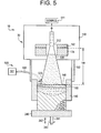
- the supply of liquid metal may comprise a casting system alone, as illustrated in Fig. 5.
- the casting system 510 in Fig. 5 comprises a casting system 2, which is similar to the nucleated casting system in Figs. 1-4.
- the casting system 2 of Fig. 5 is illustrated with a withdrawal mold 146, however, any appropriate mold is within the scope of the invention.
- the casting system 2 comprises a disruption site 134 that is positioned to receive a liquid metal stream 512 from any appropriate source 511.
- the source 511 of the liquid metal stream may comprise a vacuum arc remelting (VAR) system, a vacuum induction melting (VIR) system, an electroslag refining (ESR) system (as discussed above) with or without a cold induction guide (CIG) system, and other systems that pertain to the purification of crude or impure metals.
- VAR vacuum arc remelting
- VIR vacuum induction melting
- ESR electroslag refining
- CCG cold induction guide
- the disruption site 134 converts the liquid metal stream 512 from the source 511 into a plurality of molten metal droplets 138.
- the stream 512 can be fed to disruption site 134 in a controlled atmosphere environment 140 that is sufficient to prevent substantial and undesired oxidation of the droplets 138.
- the controlled atmosphere environment 140 may include any gas or combination of gases, which do not react with the metal of the stream 512.
- the stream 512 comprises aluminum or magnesium
- the controlled atmosphere environment 140 presents an environment that prevents the droplets 138 from becoming a fire hazard.
- the disruption site 134 can comprise any suitable device for converting the stream 512 into droplets 138.
- the disruption site 134 can comprise a gas atomizer, which circumscribes the stream 512 with one or more jets 142.
- the flow of gas from the jets 142 that impinge on the stream can be controlled, so the size and velocity of the droplets 138 can be controlled.
- Another atomizing device within the scope of the invention, includes a high pressure atomizing gas in the form of a stream of the gas, which is used to form the controlled atmosphere environment 140.
- the stream of controlled atmosphere environment 140 gas can impinge the metal stream 512 to convert the metal stream 512 into droplets 138.
- Other exemplary types of stream disruption are described above.
- the droplets 138 are broadcast downward (Fig. 1) from the disruption site 134 to form a generally diverging cone shape.
- the droplets 138 traverse a cooling zone 144, which is defined by the distance between the disruption site 134 and the upper surface 150 of the metal casting that is supported by the mold 146.
- the cooling zone 144 length is sufficient to solidify a volume fraction portion of a droplet by the time the droplet traverses the cooling zone 144 and impacts the upper surface 150 of the metal casting.
- the partially molten/partially solidified metal droplets (referred to hereinafter as "semisolid droplets") collect in mold 146.
- the mold may comprise a retractable base 246, which can be withdrawn from sidewalls of the mold 146 so as to define a withdraw mold.
- the retractable base can be connected to a shaft 241 to move base away from the sidewalls in the direction of arrow 242. Further, the shaft 241 may rotate the retractable base 246 in the direction of arrow 243 to provide most portions of the mold to a cooling system, which is described hereinafter. Details of the remainder of the casting system 2 are as set forth in the above description.
- the casting system 500 provides auxiliary cooling to the directly cooling to the liquidus portion 148 of the casting 145.
- the auxiliary cooling is in addition to the cooling that occurs during the solidification of the casting 145 itself, for example cooling that occurs by thermal conduction from walls of the mold 146.
- a casting system that is provided with a cooling system 500 can form a casting that is essentially oxide free and impurity free, and can also be densely formed and essentially non-porous because few air voids are allowed to cool in the casting due to the enhanced solidification rate resulting from the auxiliary cooling onto a liquidus portion of the casting, as embodied by the invention.
- the expedited cooling and enhanced solidification rates of the liquidus portion of the casting will enhance the microstructural characteristics of the casting by reducing the grain size, providing an essentially segregation free microstructure, and a homogeneous microstructure.
Description
- The invention relates to casting systems and methods with auxiliary cooling onto a liquidus portion of the casting. In particular, the invention related to clean metal casting systems and methods with auxiliary and direct cooling onto a liquidus portion of the casting.
- Metals, such as iron- (Fe), nickel- (Ni), titanium- (Ti), and cobalt- (Co) based alloys, are often used in turbine component applications, in which fine-grained microstructures, homogeneity, and essentially defect-free compositions are desired. Problems in superalloy castings and ingots are undesirable as the costs associated with superalloy formation are high, and results of these problems, especially in ingots formed into turbine components are undesirable. Conventional systems for producing castings have attempted to reduce the amount of impurities, contaminants, and other constituents, which may produce undesirable consequences in a component made from the casting. However, the processing and refining of relatively large bodies of metal, such as superalloys, is often accompanied by problems in achieving homogeneous, defect-free structure. These problems are believed to be due, at least in part, to the bulky volume of the metal body and the amount and depth of the liquidus metal during the casting and solidification of the ingot.
- One such problem that may often arise with respect to superalloys comprises controlling the grain size and other microstructure of the refined metals. Typically, refining processing involves multiple steps, such as sequential heating and melting, forming, cooling, and reheating of the large bodies of metal because the volume of the metal being refined is generally of at least about 5,000 pounds and can be greater than about 35,000 pounds. Further, problems of alloy or ingredient segregation also occur as processing is performed on large bodies of metal. Often, a lengthy and expensive sequence of processing steps is selected to overcome the above-mentioned difficulties, which arise through the use of bulk processing and refining operations of metals.
- A known such sequence used in industry, involves vacuum induction melting; followed by electroslag refining (such as disclosed in
US Patent Nos. 5,160,532 ;5,310,165 ;5,325,906 ;5,332,197 ;5,348,566 ;5,366,206 ;5,472,177 ;5,480,097 ;5,769,151 ;5,809,057 ; and5,810,066 , all of which are assigned to the Assignee of the instant invention); followed, in turn, by vacuum arc refining (VAR) and followed, again in turn, by mechanical working through forging and drawing to achieve a fine microstructure. While the metal produced by such a sequence is highly useful and the metal product itself is quite valuable, the processing is quite expensive and time-consuming. Further, the yield from such a sequence can be low, which results in increased costs. Furthermore, the processing sequence does not ensure defect-free metals, and ultrasonic inspection is generally employed to identify and reject any components that include such defects, which results in further increase in costs. - A conventional electroslag refining process typically uses a refining vessel that contains a slag-refining layer floating on a layer of molten refined metal. An ingot of unrefined metal is generally used as a consumable electrode and is lowered into the vessel to make contact with the molten electroslag layer. An electric current is passed through the slag layer to the ingot and causes surface melting at the interface between the ingot and the slag layer. As the ingot is melted, oxide inclusions or impurities are exposed to the slag and removed at the contact point between the ingot and the slag. Droplets of refined metal are formed, and these droplets pass through the slag and are collected in a pool of molten refined metal beneath the slag. The refined metal may then be formed into a casting or ingot (collectively referred to hereinafter as "castings").
- The above-discussed electroslag refining and the resultant casting may be dependent on a relationship between the individual process parameters, such as, but not limited to, an intensity of the refining current, specific heat input, and melting rate. This relationship involves undesirable interdependence between the rate of electroslag refining of the metal, metal ingot and casting temperatures, and rate at which a refined molten metal casting is cooled from its liquidus state to its solid state, all of which may result in poor metallurgical structure in the resultant casting.
- Further, electroslag refining may not provide for the controlling of an amount and depth of the liquidus portion in a casting. A reduced solidification rate may result in the casting having properties and characteristics that are not desirable. For example, and in no way limiting, the undesirable characteristics may include inhomogeneous microstructure, defects including (but not limited to) impurities, voids and inclusions, segregations, and a porous (non-dense) material resulting from entrapped air due to slow solidification.
- Another problem that may be associated with conventional electroslag refining processing comprises the formation of a relatively deep metal pool in an electroslag crucible. A deep melt pool causes a varied degree of ingredient macrosegregation in the metal that leads to a less desirable microstructure, such as a microstructure that is not a fine-grained microstructure, or segregation of the elemental species so as to form an inhomogeneous structure. A subsequent processing operation has been proposed in combination with the electroslag refining process to overcome this deep melt pool problem. This subsequent processing may be vacuum arc remelting (VAR). Vacuum arc remelting is initiated when an ingot is processed by vacuum arc steps to produce a relatively shallow melt pool, whereby an improved microstructure, which may also possess a lower hydrogen content, is produced. Following the vacuum arc refining process, the resulting ingot is then mechanically worked to yield a metal stock having a desirable fine-grained microstructure. Such mechanical working may involve a combination of steps of forging, drawing, and heat treatment. This thermo-mechanical processing requires large, expensive equipment, as well as costly amounts of energy input.
- An attempt to provide a desirable casting microstructure has been proposed in
US Patent No. 5,381,847 , in which a vertical casting process attempts to control grain microstructure by controlling dendritic growth. The process may be able to provide a useable microstructure for some applications, however, the vertical casting process does not control the source metal contents, including but not limited to impurities, oxides, and other undesirable constituents. The process, as set forth in the patent, does not control the depth or the liquidus portion or provide anything to enhance the solidification rate of the casting, which may adversely impact the casting's microstructure and characteristics. - Therefore, a need exists to provide a metal casting process that produces a casting with a relatively homogeneous, fine-grained microstructure, in which the process does not rely upon multiple processing steps that controls the depth of the liquidus portion of the casting. Further, a need exists to provide a metal casting system that produces a casting with a relatively homogeneous, oxide-free, fine-grained microstructure. Also, a need exists to provide a metal casting process and system that produces a casting that is essentially free of oxides and/or entrapped air due to slow solidification rates.
- The invention is defined in the claims.
- An aspect of the invention sets forth a casting system for producing a metal casting. The casting system comprises auxiliary cooling onto a liquidus portion of the casting and can produce a metal casting that comprises a fine-grain, homogeneous microstructure. The microstructure is oxide- and sulfide-free, segregation defect free, and free of voids caused by air entrapped during solidification of the metal from a liquidus state to a solid state. The casting system with auxiliary cooling onto a liquidus portion of the casting comprises an electroslag refining system; source of liquid metal, such as a casting system; and at least one cooling system that supplies coolant onto a liquidus portion of the casting. The casting is cooled in a manner sufficient to provide a microstructure that comprises a fine-grain, homogeneous microstructure that is oxide- and sulfide-free, segregation defect free, and free of voids caused by air entrapped during solidification from a liquidus state to a solid state.
- A further aspect of the invention provides a method for forming a metal casting using auxiliary cooling onto a liquidus portion of the casting. The method produces a metal casting that comprises a fine-grain, homogeneous microstructure that is essentially oxide- and sulfide-free, segregation defect free, and essentially free of voids caused by air entrapped during solidification of the metal from a liquidus state to a solid state. The method comprises forming a source of clean refined metal that has oxides and sulfides refined out by electroslag refining; forming the casting by a casting process; and cooling a liquidus portion of the casting. The cooling comprises directing coolant onto the liquidus portion of the casting, wherein the step of cooling is sufficient to provide a microstructure that comprises a fine-grain, homogeneous microstructure that is oxide- and sulfide-free, segregation defect free, and free of voids caused by air entrapped during solidification from a liquidus state to a solid state.
- These and other aspects, advantages and salient features of the invention will become apparent from the following detailed description, which, when taken in conjunction with the annexed drawings, where like parts are designated by like reference characters throughout the drawings, disclose embodiments of the invention.
-
- Figure 1 is a schematic illustration of a clean metal casting system with auxiliary cooling onto a liquidus portion of the casting having cooling system, an electroslag refining system, and casting system;
- Figure. 2 is a partial schematic, vertical sectional illustration of the clean metal casting system, as illustrated in Fig. 1, that illustrates details of the electroslag refining system;
- Figure 3 is a partial schematic, vertical section illustration in detail of the electroslag refining system of the clean metal casting system for producing a casting;
- Figure 4 is a partial schematic, part sectional illustration of the electroslag refining system of the clean metal casting system for producing a casting; and
- Figure 5 is a schematic illustration of a further casting system with a casting system and auxiliary cooling onto a liquidus portion of the casting.
- Casting systems and methods with auxiliary cooling onto a liquidus portion of the casting, as embodied by the invention, can be provided on casting systems, such as, but not limited to, vertical casting systems and casting systems that include vertical casting with electroslag refining and cold-induction guides. The systems and methods with auxiliary cooling onto a liquidus portion of the casting will be described hereinafter with respect to vertical casting with electroslag refining and cold-induction guides, as illustrated in Figs. 1-4. However, this description is not intended to limit the invention in any way, and the scope of the invention comprises casting systems and methods with auxiliary cooling onto a liquidus portion of the casting with other metal formation processes and systems.
- The casting systems and methods with auxiliary cooling onto a liquidus upper portion (liquidus portion) of the casting, and alternatively, auxiliary and direct cooling onto a liquidus portion of the casting (hereinafter referred to as "auxiliary cooling onto the liquidus portion") can produce a casting with oxide free and impurity free characteristics. The casting that is formed can also be dense and non-porous. The term "casting" includes any casting, such as a preform, ingot, and the like.
- The clean-liquid metal source for the casting systems and methods with auxiliary cooling onto a liquidus portion of the casting, as embodied by the invention, can comprise any appropriate liquid metal source, such as, but not limited to, an electroslag refining apparatus, which can provide a clean liquid metal due to the electroslag refining steps. For example, and in no way limiting the invention, the electroslag refining apparatus can comprise an electroslag refining (ESR) system in cooperation with a cold-induction guide (CIG), as set forth in the above-mentioned patents to the Assignee of the instant invention.
- Alternatively, the source for the casting systems and methods with auxiliary cooling onto a liquidus portion of the casting can comprise a vertical casting arrangement, as disclosed in
US Patent No. 5,381,847 . Therefore, a casting system may permit a plurality of molten metal droplets to be formed and pass through a cooling zone, which is formed with a length sufficient to allow up to about 30 volume percent of each of the droplets to solidify on average. The droplets are then received by a mold and solidification of the metal droplets is completed in the mold, such as, but not limited to, auxiliary cooling, as embodied by the invention. The droplets retain liquid characteristics and readily flow within the mold, when less than about 30 volume percent of the droplets is solid. - In order to enhance the solidification rate of the liquidus portion of the metal, the casting systems and methods, as embodied by the invention, provide coolant directly onto the liquidus (upper) portion of the casting to enhance cooling of the liquidus portion of the casting. The coolant will reduce the temperature of the liquidus portion of the casting, and provide expedited cooling and enhanced solidification of the liquidus portion of the casting. The expedited cooling and enhanced solidification of the liquidus portion will reduce the amount of entrapped gas that can be generated during operation or retained therein, thus forming a dense casting that contains few entrapped gas voids. Further, the expedited cooling and enhanced solidification rates of the liquidus portion will enhance the microstructural characteristics of the casting by reducing the grain size, providing an essentially segregation free microstructure, and a homogeneous microstructure. The auxiliary cooling onto a liquidus portion of the casting, as embodied by the invention, can produce a casting possessing a homogeneous, fine-grained microstructure for many metals and alloys, including, but not limited to, nickel- (Ni) and cobalt- (Co) based superalloys, iron- (Fe), titanium- (Ti), alloys, which are often used in turbine component applications. The castings formed by the auxiliary cooling onto a liquidus portion of the casting, as embodied by the invention, can be converted into a final casting, a billet, or directly forged with reduced processing and heat treatment steps, due to their homogeneous, fine-grained microstructure.
- Accordingly, a casting method including auxiliary cooling onto a liquidus portion of the casting can be used to produce high quality forgings that can be used in many applications, such as but not limited to rotating equipment applications, such as, but not limited to, disks, rotors, blades, vanes, wheel, buckets, rings, shafts, wheels, and other such elements, and other turbine component applications. The description of the invention will refer to turbine components formed from castings, however, this is merely exemplary of the applications within the scope of the invention.
- Referring to the accompanying drawings, Fig. 1 illustrates a semi-schematic, part-sectional, elevational view of an
exemplary casting system 3 with auxiliary cooling onto a liquidus portion of the casting by acooling system 500, as embodied by the invention. Figures 2-4 illustrate details of features illustrated in Fig. 1. Thecasting system 3 will be initially discussed with a description of theelectroslag refining system 1 and thenucleated casting system 2 to facilitate the understanding of the invention. - Figure 1 is a schematic illustration of a
casting system 3 with anauxiliary cooling system 500 for cooling of a liquidus portion of the casting, as embodied by the invention, for producing acasting 145. In Fig. 1, the metal for the cleanmetal casting system 3 and its associated clean metal casting processes is provided by anelectroslag refining system 1. The clean metal is fed to acasting system 2. Theelectroslag refining system 1 andcasting system 2 cooperate to form a cleanmetal casting system 3, which in turn forms the auxiliary cooling onto a liquidus portion of the casting, as embodied by the invention. - The
electroslag refining system 1 introduces aconsumable electrode 24 of metal to be refined directly into anelectroslag refining system 1, and refines theconsumable electrode 24 to produce a clean, refined metal melt 46 (hereafter "clean metal"). The source of metal for theelectroslag refining system 1 as aconsumable electrode 24 is merely exemplary, and the scope of the invention comprises, but is not limited to, the source metal comprising an ingot, melt of metal, powder metal, and combinations thereof. The description of the invention will refer to a consumable electrode, however this is merely exemplary and is not intended to limit the invention in any manner. Theclean metal 46 is received and retained within acold hearth structure 40 that is mounted below theelectroslag refining apparatus 1. Theclean metal 46 is dispensed from thecold hearth structure 40 through a coldfinger orifice structure 80 that is mounted and disposed below thecold hearth structure 40. - The
electroslag refining system 1 can provide essentially steady state operation in supplyingclean metal 46 if the rate of electroslag refining of metal and rate of delivery of refined metal to acold hearth structure 40 approximates the rate at whichmolten metal 46 is drained from thecold hearth structure 40 through anorifice 81 of the coldfinger orifice structure 80. Thus, the clean metal casting process can operate continuously for an extended period of time and, accordingly, can process a large bulk of metal. Alternatively, the clean metal casting process can be operated intermittently by intermittent operation of one or more of the features of the cleanmetal casting system 3. - Once the
clean metal 46 exits theelectroslag refining system 1 through the coldfinger orifice structure 80, it enters into thecasting system 2. Then, theclean metal 46 can be further processed to produce a relatively large ingot of refined metal. Alternatively, theclean metal 46 may be processed through to produce smaller castings, ingots, castings, or formed into continuous cast castings. The clean metal casting process effectively eliminates many of the processing operations, such as those described above that, until now, have been necessary in order to produce a metal casting having a desired set of material characteristics and properties. - In Fig. 1, a vertical
motion control apparatus 10 is schematically illustrated. The verticalmotion control apparatus 10 comprises a box 12 mounted to avertical support 14 that includes a motive device (not illustrated), such as but not limited to a motor or other mechanism. The motive device is adapted to impart rotary motion to ascrew member 16. Aningot support structure 20 comprises a member, such as but not limited to amember 22, that is threadedly engaged at one end to thescrew member 16. Themember 22 supports theconsumable electrode 24 at its other end by an appropriate connection, such as, but not limited to, abolt 26. - An
electroslag refining structure 30 comprises areservoir 32 that is cooled by an appropriate coolant, such as, but not limited to, water. Thereservoir 32 comprises amolten slag 34, in which an excess of theslag 34 is illustrated as thesolid slag granules 36. The slag composition used in the clean metal casting process will vary with the metal being processed. Aslag skull 75 may be formed along inside surfaces of aninner wall 82 ofreservoir 32, due to the cooling influence of the coolant flowing against the outside ofinner wall 82, as described hereinafter. - A cold hearth structure 40 (Figs. 1-3) is mounted below the
electroslag refining structure 30. Thecold hearth structure 40 comprises ahearth 42, which is cooled by an appropriate coolant, such as water. Thehearth 42 contains askull 44 of solidified refined metal and abody 46 of refined liquid metal. Thereservoir 32 may be formed integrally with thehearth 42. Alternatively, thereservoir 32 andhearth 42 may be formed as separate units, which are connected to form theelectroslag refining system 1. - A
bottom orifice 81 of theelectroslag refining system 1 is provided in the coldfinger orifice structure 80, which is described with reference to Figs. 3 and 4. Aclean metal 46, which is refined by theelectroslag refining system 1 so as to be essentially free of oxides, sulfides, and other impurities, can traverse theelectroslag refining system 1 and flow out of theorifice 81 of the coldfinger orifice structure 80. - A
power supply structure 70 can supply electric refining current to theelectroslag refining system 1. Thepower supply structure 70 can comprise an electric power supply andcontrol mechanism 74. Anelectrical conductor 76 that is able to carry current to themember 22 and, in turn, carry current to theconsumable electrode 24 connects thepower supply structure 70 to themember 22. Aconductor 78 is connected to thereservoir 32 to complete a circuit for thepower supply structure 70 of theelectroslag refining system 1. - Figure 2 is a detailed part-sectional illustration of the
electroslag refining structure 30 and thecold hearth structure 40 in which theelectroslag refining structure 30 defines an upper portion of thereservoir 32 and thecold hearth structure 40 defines alower portion 42 of thereservoir 32. Thereservoir 32 generally comprises a double-walled reservoir, which includes aninner wall 82 andouter wall 84. Acoolant 86, such as but not limited to water, is provided between theinner wall 82 andouter wall 84. Thecoolant 86 can flow to and through a flow channel, which is defined between theinner wall 82 andouter wall 84 from a supply 98 (Fig. 3) and through conventional inlets and outlets (not illustrated in the figures). The coolingwater 86 that cools thewall 82 of thecold hearth structure 40 provides cooling to theelectroslag refining structure 30 and thecold hearth structure 40 to cause theskull 44 to form on the inner surface of thecold hearth structure 40. Thecoolant 86 is not essential for operation of theelectroslag refining system 1, cleanmetal casting system 3, orelectroslag refining structure 30. Cooling may insure that theliquid metal 46 does not contact and attack theinner wall 82, which may cause some dissolution from thewall 82 and contaminate theliquid metal 46. - In Fig. 2, the
cold hearth structure 40 also comprises an outer wall 88, which may include flanged tubular sections, 90 and 92. Two flangedtubular sections casting system 2 to form a controlledatmosphere environment 140, which is described hereinafter. - The
cold hearth structure 40 comprises a coldfinger orifice structure 80 that is shown detail Figs. 3 and 4. The coldfinger orifice structure 80 is illustrated in Fig. 3 in relation to thecold hearth structure 40 and astream 56 ofliquid melt 46 that exits thecold hearth structure 40 through the coldfinger orifice structure 80. The coldfinger orifice structure 80 is illustrated (Figs. 2 and 3) in structural cooperation with thesolid metal skull 44 andliquid metal 46. Figure 4 illustrates the coldfinger orifice structure 80 without the liquid metal or solid metal skull, so details of the coldfinger orifice structure 80 are illustrated. - The cold
finger orifice structure 80 comprises theorifice 81 from which processedmolten metal 46 is able to flow in the form of astream 56. The coldfinger orifice structure 80 is connected to thecold hearth structure 40 and thecold hearth structure 30. Therefore, thecold hearth structure 40 allows processed and generally impurity-free alloy to form theskulls cold hearth structure 40. Theskulls molten metal 46. Additionally, the skull 83 (Fig. 3), which is formed at the coldfinger orifice structure 80, is controllable in terms of its thickness, and is typically formed with a smaller thickness than theskull 44. Thethicker skull 44 contacts thecold hearth structure 40 and thethinner skull 83 contacts the coldfinger orifice structure 80, and theskulls - A controlled amount of heat may be provided to the
skull 83 and thermally transmitted to theliquid metal body 46. The heat is provided from induction heating coils 85 that are disposed around the cold hearth structure. An induction-heating coil 85 can comprise a cooled induction-heating coil, by flow of an appropriate coolant, such as water, into it from asupply 87. Induction heating power is supplied from apower source 89, which is schematically illustrated in Fig. 3. The construction of the coldfinger orifice structure 80 permits heating by induction energy to penetrate the coldfinger orifice structure 80 and heat theliquid metal 46 andskull 83, and maintain theorifice 81 open so that thestream 56 may flow out of theorifice 81. The orifice may be closed by solidification of thestream 56 ofliquid metal 46 if heating power is not applied to the coldfinger orifice structure 80. The heating is dependent on each of the fingers of the coldfinger orifice structure 80 being insulated from the adjoining fingers, for example being insulated by an air or gas gap or by a suitable insulating material. - The cold
finger orifice structure 80 is illustrated in Fig. 4, with bothskulls molten metal 46 are omitted for clarity. An individualcold finger 97 is separated from each adjoining finger, such asfinger 92, by a gap 94. The gap 94 may be provided and filled with an insulating material, such as, but not limited to, a ceramic material or insulating gas. Thus, the molten metal 46 (not illustrated) that is disposed within the coldfinger orifice structure 80 does not leak out through the gaps, because theskull 83 creates a bridge over the cold fingers and prevents passage ofliquid metal 46 therethrough. Each gap extends to the bottom of the coldfinger orifice structure 80, as illustrated in Fig. 4, which illustrates agap 99 aligned with a viewer's line-of-sight. The gaps can be provided with a width in a range from about of 20 mils to about 50 mils, which is sufficient to provide an insulated separation of respective adjacent fingers. - The individual fingers may be provided with a coolant, such as water, by passing coolant into a
conduit 96 from a suitable coolant source (not shown). The coolant is then passed around and through a manifold 98 to the individual cooling tubes, such ascooling tube 100. Coolant that exits the coolingtube 100 flows between an outside surface of thecooling tube 100 and an inside surface of a finger. The coolant is then collected in a manifold 102, and passed out of the coldfinger orifice structure 80 through awater outlet tube 104. This individual cold finger water supply tube arrangement allows for cooling of the coldfinger orifice structure 80 as a whole. - The amount of heating or cooling that is provided through the cold
finger orifice structure 80 to theskulls liquid metal 46, can be controlled to control the passage ofliquid metal 46 through theorifice 81 as astream 56. The controlled heating or cooling is done by controlling the amount of current and coolant that pass in the induction coils 85 to and through the coldfinger orifice structure 80. The controlled heating or cooling can increase or decrease the thickness of theskulls orifice 81, or to reduce or increase the passage of thestream 56 through theorifice 81. More or lessliquid metal 46 can pass through the coldfinger orifice structure 80 into theorifice 81 to define thestream 56 by increasing or decreasing the thickness of theskulls stream 56 can be maintained at a desirable balance, by controlling coolant water and heating current and power to and through theinduction heating coil 85 to maintain theorifice 81 at a set passage size along with controlling the thickness of theskulls - The operation of the
electroslag refining system 1 of the cleanmetal casting system 3 will now be generally described with reference to the figures. Theelectroslag refining system 1 of the cleanmetal casting system 3 can refine ingots that can include defects and impurities. Aconsumable electrode 24 is melted by theelectroslag refining system 1. Theconsumable electrode 24 is mounted in theelectroslag refining system 1 in contact with molten slag in the electroslag refining system. Electrical power is provided to the electroslag refining system and ingot. The power causes melting of the ingot at a surface where it contacts the molten slag and the formation of molten drops of metal. The drops are collected after they pass through the molten slag as a body of refined liquid metal in thecold hearth structure 40 below theelectroslag refining structure 30. Oxides, sulfides, contaminants, and other impurities that originate in theconsumable electrode 24 are removed through dissolution in to the slag as the droplets form on the surface of the ingot and pass through the molten slag. The molten drops are drained from theelectroslag refining system 1 at theorifice 81 in the coldfinger orifice structure 80 as astream 56. Thestream 56 that exits theelectroslag refining system 1 of the cleanmetal casting system 3 that forms castings comprises a refined melt that is free of oxides, sulfides, contaminants, and other impurities. - The rate at which the
metal stream 56 exits the coldfinger orifice structure 80 can further be controlled by controlling a hydrostatic head ofliquid metal 46 above theorifice 81. Theliquid metal 46 andslag orifice 81 of the coldfinger orifice structure 80 define the hydrostatic head. If a cleanmetal casting system 3 with anelectroslag refining system 1 is operated with a given constant hydrostatic head and a constantsized orifice 81, an essentially constant flow rate of liquid metal can be established. - Typically, a steady state of power is desired so the melt rate is generally equal to the removal rate from the clean
metal casting system 3, as astream 56. However, the current applied to the cleanmetal casting system 3 can be adjusted to provide more or lessliquid metal 46 andslag orifice 81. The amount ofliquid metal 46 andslag orifice 81 is determined by the power that melts the ingot, and the cooling of theelectroslag refining system 1, which create the skulls. By adjusting the applied current, flow through theorifice 81 can be controlled. - Also, the contact of the
consumable electrode 24 with an upper surface of themolten slag 34 can be maintained in order to establish a steady state ofoperation 1. A rate ofconsumable electrode 24 descent into themelt 46 can be adjusted to ensure that contact of theconsumable electrode 24 with the upper surface of themolten slag 34 is maintained for the steady state operation. Thus, a steady-state discharge from thestream 56 can be maintained in the cleanmetal casting system 3. Thestream 56 of metal that is formed in theelectroslag refining system 1 of the cleanmetal casting system 3 exitselectroslag refining system 1 and is fed to acasting system 2. Thecasting system 2 is schematically illustrated in Fig. 1 in cooperation with theelectroslag refining system 1. - The
casting system 2 comprises adisruption site 134 that is positioned to receive thestream 56 from theelectroslag refining system 1 of the cleanmetal casting system 3. Thedisruption site 134 converts thestream 56 into a plurality ofmolten metal droplets 138. Thestream 56 can be fed todisruption site 134 in a controlledatmosphere environment 140 that is sufficient to prevent substantial and undesired oxidation of thedroplets 138. The controlledatmosphere environment 140 may include any gas or combination of gases, which do not react with the metal of thestream 56. For example, if thestream 56 comprises aluminum or magnesium, the controlledatmosphere environment 140 presents an environment that prevents thedroplets 138 from becoming a fire hazard. Typically, any noble gas or nitrogen is suitable for use in the controlledatmosphere environment 140 because these gases are generally non-reactive with most metals and alloys within the scope of the invention. For example, nitrogen, which is a low-cost gas, can be in the controlledatmosphere environment 140, except for metals and alloys that are prone to excessive nitriding. Also, if the metal comprises copper, the controlledatmosphere environment 140 may comprise nitrogen, argon, and mixtures thereof. If the metal comprises nickel or steel, the controlledatmosphere environment 140 can comprises nitrogen or argon, or mixtures thereof. - The
disruption site 134 can comprise any suitable device for converting thestream 56 intodroplets 138. For example, thedisruption site 134 can comprise a gas atomizer, which circumscribes thestream 56 with one ormore jets 142. The flow of gas from thejets 142 that impinge on the stream can be controlled, so the size and velocity of thedroplets 138 can be controlled. Another atomizing device, within the scope of the invention, includes a high pressure atomizing gas in the form of a stream of the gas, which is used to form the controlledatmosphere environment 140. The stream of controlledatmosphere environment 140 gas can impinge themetal stream 56 to convert themetal stream 56 intodroplets 138. Other exemplary types of stream disruption include magneto-hydrodynamic atomization, in which thestream 56 flows through a narrow gap between two electrodes that are connected to a DC power supply with a magnet perpendicular to the electric field, and mechanical-type stream disruption devices. - The
droplets 138 are broadcast downward (Fig. 1) from thedisruption site 134 to form a generally diverging cone shape. Thedroplets 138 traverse acooling zone 144, which is defined by the distance between thedisruption site 134 and theupper surface 150 of the metal casting that is supported by themold 146. Thecooling zone 144 length is sufficient to solidify a volume fraction portion of a droplet by the time the droplet traverses thecooling zone 144 and impacts theupper surface 150 of the metal casting. The portion of thedroplet 138 that solidifies (hereinafter referred to as the "solid volume fraction portion") is sufficient to inhibit coarse dendritic growth in themold 146 up to a viscosity inflection point at which liquid flow characteristics in the mold are essentially lost. - The partially molten/partially solidified metal droplets (referred to hereinafter as "semisolid droplets") collect in
mold 146. The mold may comprise a unitary and one-piece mold, as illustrated in the broken lines of Fig. 1. Alternatively, the mold may comprises a withdrawal mold, which includes aretractable base 246 that can be withdrawn from sidewalls of themold 146. The following description of the invention will discuss a withdrawal mold as an exemplary, non-limiting mold, and is not intended to limit the invention in any manner. Theretractable base 246 can be connected to ashaft 241 to move base away from the sidewalls in the direction ofarrow 242. Further, theshaft 241 may rotate theretractable base 246 in the direction ofarrow 243 to provide most portions of the mold to a cooling system, which is described hereinafter. The semisolid droplets behave like a liquid if the solid volume fraction portion is less than a viscosity inflection point, and the semisolid droplets exhibit sufficient fluidity to conform to the shape of the mold. Generally, an upper solid volume fraction portion limit that defines a viscosity inflection point is less than about 40% by volume. An exemplary solid volume fraction portion is in a range from about 5% to about 40%, and a solid volume fraction portion in a range from about 15% to about 30% by volume does not adversely influence the viscosity inflection point. - The spray of
droplets 138 creates a liquidus,upper portion 148 disposed proximate the surface of the casting 145 in themold 146. The depth of the liquidus,upper portion 148 is dependent on cooling of the liquidus portion, the solidification rate thereof, and various cleanmetal casting system 3 factors, such as, but not limited to, the atomization gas velocity, droplet velocity, thecooling zone 144 length, the stream temperature, and droplet size. The liquidus,upper portion 148 can be created with a depth in themold 146 in a range from about 0.005 inches to about 1.0 inches. An exemplary liquidus,upper portion 148 within the scope of invention comprises a depth in a range from about 0.25 to about 0.50 inches in the mold. In general, the liquidus,upper portion 148 in themold 146 should not be greater that a region of the casting, where the metal exhibits predominantly liquid characteristics. Typically, expedited solidification of the liquidus portion minimizes gas entrapment and resultant pores in the casting. - A cooling system 500 (Fig. 1), as embodied by the invention, can extract heat from the
liquidus portion 148 of the casting 145 to expedite its cooling and enhance its solidification. Thecooling system 500 comprises acoolant supply 501. The coolant can comprise any appropriate coolant, such as, but not limited to, an inert cooling gas that will not react with the material of the casting. Exemplary cooling gases within the scope of the invention comprise, but are not limited to, argon, nitrogen, and helium. In thecooling system 500, the coolant is directed onto the liquidus portion of the casting 145, while the casting 145 can be withdrawn from themold 146, if the mold comprises a withdrawal mold. The coolant exits thecooling system 500 in the form of aspray 503 after passing through acoolant conduit 502 from thecoolant supply 501. Thecoolant conduit 502 can comprise any appropriate conduit that allows passage of the coolant from thecoolant source 501 to a position proximate theliquidus portion 148 of acasting 145. The shape and configuration of thecoolant conduit 502 may take any shape and configuration as long as the coolant can be directed to theliquidus portion 148 of the casting 145, such as inside thezone 144. While the illustrations set forth thecoolant conduit 502 being curved and angled, this shape and configuration is merely exemplary, and is not intended to limit the invention in any manner. Other shapes and configurations of thecoolant conduit 502, for example, but not limited to, straight and coiled, are within the scope of the invention. - The
cooling system 500, as embodied by the invention, can comprise a configuration as illustrated. Further, thecooling system 500 can comprise a plurality of one or all of the elements of thecooling system 500. For example, and in no way limiting of the invention, thecooling system 500 can comprise one source that is in fluidic communication with a plurality ofcoolant conduits 502 to form a plurality ofsprays 503. Further, thecooling system 500 can comprise a plurality ofsupplies 501, each communicating with acoolant conduit 502 andcoolant spray 503. Also, acoolant conduit 502 may form a plurality ofsprays 503 from asingle coolant conduit 502. The above descriptions are merely exemplary and are not intended to limit the invention in any manner. - The
mold 146 can be formed of any suitable material for casting applications, such as but not limited to, graphite, cast iron, and copper. Graphite is asuitable mold 146 material since it is relatively easy to machine and exhibits satisfactory thermal conductivity for heat removal via the cooling systems, as embodied by the invention. As themold 146 is filled withsemisolid droplets 138, itsupper surface 150 moves closer to thedisruption site 134, and thecooling zone 144 is reduced. At least one of thedisruption site 134 or themold 146 may be mounted on a moveable support and separated at a fixed rate to maintain aconstant cooling zone 144 dimension. Thus, a generally consistent solid volume fraction portion in thedroplets 138 is formed.Baffles 152 may be provided in thecasting system 2 to extend the controlledatmosphere environment 140 from theelectroslag refining system 1 to themold 146. Thecooling system 500 can extend through thebaffles 152, as illustrated in the figures. Thebaffles 152 can prevent oxidation of the partiallymolten metal droplets 138 and conserve the controlledatmosphere environment gas 140. Heat that is extracted from the casting 145 completes the solidification process of the liquidusupper portion 148 of the casting 145 to form solidified castings for further use. Sufficient nuclei are formed in casting 145 produced so that upon solidification, a fineequiaxed microstructure 149 can be formed in thecasting 145. - The
casting system 3 inhibits undesirable dendritic growth, reduces solidification shrinkage porosity of the formed casting and casting, and reduces hot tearing both during casting and during subsequent hot working of the casting and casting. Further, the cleanmetal casting system 3 produces a uniform, equiaxed structure in the casting which is a result of the minimal distortion of the mold during casting, the controlled transfer of heat during solidification of the casting in the mold, and controlled nucleation. The cleanmetal casting system 3 enhances ductility and fracture toughness of the casting compared to conventionally castings. - The above-described
cooling system 500 has been discussed in regard to acasting system 3, which comprises anelectroslag refining system 1 as a source of liquid metal, acasting system 2, and acooling system 500. However, the scope of the invention further comprises use of cooling systems, as embodied by the invention, with a casting system that comprises a casting system with any appropriate source of liquid metal. For example, the supply of liquid metal may comprise a casting system alone, as illustrated in Fig. 5. The casting system 510 in Fig. 5 comprises acasting system 2, which is similar to the nucleated casting system in Figs. 1-4. Thecasting system 2 of Fig. 5 is illustrated with awithdrawal mold 146, however, any appropriate mold is within the scope of the invention. - The
casting system 2 comprises adisruption site 134 that is positioned to receive aliquid metal stream 512 from anyappropriate source 511. For example, and in no way limiting of the invention, thesource 511 of the liquid metal stream may comprise a vacuum arc remelting (VAR) system, a vacuum induction melting (VIR) system, an electroslag refining (ESR) system (as discussed above) with or without a cold induction guide (CIG) system, and other systems that pertain to the purification of crude or impure metals. The above systems are merely exemplary, and are not intended to limit the invention in any manner. - The
disruption site 134 converts theliquid metal stream 512 from thesource 511 into a plurality ofmolten metal droplets 138. Thestream 512 can be fed todisruption site 134 in a controlledatmosphere environment 140 that is sufficient to prevent substantial and undesired oxidation of thedroplets 138. The controlledatmosphere environment 140 may include any gas or combination of gases, which do not react with the metal of thestream 512. For example, if thestream 512 comprises aluminum or magnesium, the controlledatmosphere environment 140 presents an environment that prevents thedroplets 138 from becoming a fire hazard. - The
disruption site 134 can comprise any suitable device for converting thestream 512 intodroplets 138. For example, thedisruption site 134 can comprise a gas atomizer, which circumscribes thestream 512 with one ormore jets 142. The flow of gas from thejets 142 that impinge on the stream can be controlled, so the size and velocity of thedroplets 138 can be controlled. Another atomizing device, within the scope of the invention, includes a high pressure atomizing gas in the form of a stream of the gas, which is used to form the controlledatmosphere environment 140. The stream of controlledatmosphere environment 140 gas can impinge themetal stream 512 to convert themetal stream 512 intodroplets 138. Other exemplary types of stream disruption are described above. - The
droplets 138 are broadcast downward (Fig. 1) from thedisruption site 134 to form a generally diverging cone shape. Thedroplets 138 traverse acooling zone 144, which is defined by the distance between thedisruption site 134 and theupper surface 150 of the metal casting that is supported by themold 146. Thecooling zone 144 length is sufficient to solidify a volume fraction portion of a droplet by the time the droplet traverses thecooling zone 144 and impacts theupper surface 150 of the metal casting. The partially molten/partially solidified metal droplets (referred to hereinafter as "semisolid droplets") collect inmold 146. The mold may comprise aretractable base 246, which can be withdrawn from sidewalls of themold 146 so as to define a withdraw mold. The retractable base can be connected to ashaft 241 to move base away from the sidewalls in the direction ofarrow 242. Further, theshaft 241 may rotate theretractable base 246 in the direction ofarrow 243 to provide most portions of the mold to a cooling system, which is described hereinafter. Details of the remainder of thecasting system 2 are as set forth in the above description. - The
casting system 500 provides auxiliary cooling to the directly cooling to theliquidus portion 148 of the casting 145. The auxiliary cooling is in addition to the cooling that occurs during the solidification of the casting 145 itself, for example cooling that occurs by thermal conduction from walls of themold 146. Thus, a casting system that is provided with acooling system 500, as embodied by the invention, can form a casting that is essentially oxide free and impurity free, and can also be densely formed and essentially non-porous because few air voids are allowed to cool in the casting due to the enhanced solidification rate resulting from the auxiliary cooling onto a liquidus portion of the casting, as embodied by the invention. Further, the expedited cooling and enhanced solidification rates of the liquidus portion of the casting will enhance the microstructural characteristics of the casting by reducing the grain size, providing an essentially segregation free microstructure, and a homogeneous microstructure. - While various embodiments are described herein, it will be appreciated from the specification that various combinations of elements, variations or improvements therein may be made by those skilled in the art, and are within the scope of the invention.
Claims (8)
- A casting system (3) with auxiliary cooling onto a liquidus portion (148) of the casting for producing a metal casting (145), the metal casting comprising a fine-grain, homogeneous microstructure that is oxide- and sulfide-free, segregation defect free, and free of voids caused by air entrapped during solidification of the metal from a liquidus state to a solid state, the casting system with auxiliary cooling onto a liquidus portion of the casting comprising:an electroslag refining system (1);
a casting system (2) in which molten metal droplets (138) are directed into a mold (146); and
at least one cooling system (500) that supplies coolant onto a liquidus portion of the casting in the mold. - A casting system according to claim 1, wherein the electroslag refining system comprises:an electroslag refining structure (30) adapted to receive and to hold a refining molten slag,a source of metal (24) to be refined in the electroslag refining structure;a body of molten slag (34) in the electroslag refining structure, the source of metal being disposed in contact with the molten slag,an electric supply (70) adapted to supply electric current to the source of metal as an electrode and through the molten slag to a body of refined metal beneath the slag to keep the refining slag molten and to melt the end of the source of metal in contact with the slag,an advancing device (10) for advancing the source of metal into contact with the molten slag at a rate corresponding to the rate at which the contacted surface of the electrode is melted as the refining thereof proceeds,a cold hearth structure (40) beneath the electroslag refining structure, the cold hearth structure being adapted to receive and to hold electroslag refined molten metal in contact with a solid skull of the refined metal formed on the walls of the cold hearth vessel,a body (46) of refined molten metal in the cold hearth structure beneath the molten slag,a cold finger orifice structure (80) below the cold hearth adapted to receive and to dispense a stream (56) of refined molten metal that is processed by the electroslag refining system and through the cold hearth structure, the cold finger orifice structure having a orifice,a skull (44) of solidified refined metal in contact with the cold hearth structure and the cold finger orifice structure including the orifice.
- A casting system according to claim 1, wherein the casting system in which molten metal droplets (138) are directed into a mold (146) comprises:a disruption site (134) through which a stream of liquid metal is formed into molten metal droplets (138); anda cooling zone (144) that that receives the molten metal droplets, the molten metal droplets being solidified in the cooling zone into semisolid droplets such that, on average, 5% to 40% by volume of each semisolid droplet is solid and the remainder of the semisolid droplet is molten; anda mold (146) that collects the droplets in a liquidus portion and solidifies the droplets thereby forming the casting.
- A casting system according to claim 1, wherein the liquidus portion of the casting is generated by metal droplets in an upper area of the casting and, within the liquidus portion, on average, less than 50% by volume of an average droplet is solid.
- A casting system according to claim 1, wherein the cooling system comprises:a coolant supply (501) and a coolant conduit (502) to apply coolant directly onto a liquidus portion of the casting.
- A casting system according to claim 6, wherein the coolant conduit applies coolant as a spray (503).
- A casting method with auxiliary cooling onto a liquidus portion of the casting for forming a metal casting, the metal casting comprising a fine-grain, homogeneous microstructure that is oxide- and sulfide-free, segregation defect free, and free of voids caused by air entrapped during solidification of the metal from a liquidus state to a solid state, the method with auxiliary cooling onto a liquidus portion of the casting comprising:forming a source of clean refined metal that has oxides and sulfides refined out by electroslag refining:forming a casting (145) by a casting process in which molten metal droplets (138) are directed into a mold (146); andcooling a liquidus portion of the casting, the step of cooling comprising directing coolant onto the liquidus portion of the casting in the mold.
- A method according to claim 7, wherein the step of forming a source comprises electroslag refining that comprises:providing a source of metal (1) to be refined;providing an electroslag refining structure (30) adapted for the electroslag refining of the source of metal and providing molten slag (34) in the vessel;providing a cold hearth structure (40) for holding a refined molten metal beneath the molten slag and providing refined molten metal in the cold hearth structure;mounting the source of metal (24) for insertion into the electroslag refining structure and into contact with the molten slag in the electroslag refining structure;providing an electrical power supply (70) adapted to supply electric power;supplying electric power to electroslag refine the source of metal through a circuit, the circuit comprising the power supply, the source of metal, the molten slag and the electroslag refining structure;resistance melting of the source of metal where the source of metal contacts the molten slag and forming molten droplets of metal;allowing the molten droplets to fall through the molten slag;collecting the molten droplets after they pass through the molten slag as a body of refined liquid metal in the cold hearth structure directly below the electroslag refining structure;providing a cold finger orifice structure (80) having a orifice at the lower portion of the cold hearth structure; anddraining the electroslag refined metal that collects in the cold hearth orifice structure through the orifice of the cold finger orifice structure.
Applications Claiming Priority (3)
| Application Number | Priority Date | Filing Date | Title |
|---|---|---|---|
| US496752 | 2000-02-03 | ||
| US09/496,752 US6427752B1 (en) | 1999-02-23 | 2000-02-03 | Casting systems and methods with auxiliary cooling onto a liquidus portion of a casting |
| PCT/US2000/014521 WO2001057283A1 (en) | 2000-02-03 | 2000-05-26 | Casting systems and methods with auxiliary cooling onto a liquidus portion of a casting |
Publications (2)
| Publication Number | Publication Date |
|---|---|
| EP1263997A1 EP1263997A1 (en) | 2002-12-11 |
| EP1263997B1 true EP1263997B1 (en) | 2007-10-03 |
Family
ID=23973969
Family Applications (1)
| Application Number | Title | Priority Date | Filing Date |
|---|---|---|---|
| EP00937809A Expired - Lifetime EP1263997B1 (en) | 2000-02-03 | 2000-05-26 | Casting systems and methods with auxiliary cooling onto a liquidus portion of a casting |
Country Status (6)
| Country | Link |
|---|---|
| US (1) | US6427752B1 (en) |
| EP (1) | EP1263997B1 (en) |
| JP (1) | JP2003521377A (en) |
| KR (1) | KR100628591B1 (en) |
| DE (1) | DE60036646T2 (en) |
| WO (1) | WO2001057283A1 (en) |
Cited By (1)
| Publication number | Priority date | Publication date | Assignee | Title |
|---|---|---|---|---|
| CN103398588A (en) * | 2013-07-26 | 2013-11-20 | 朱兴发 | Underflow-type flow-controllable electric-heating graphite nozzle device of electromagnetic induction slag smelter |
Families Citing this family (11)
| Publication number | Priority date | Publication date | Assignee | Title |
|---|---|---|---|---|
| US8891583B2 (en) | 2000-11-15 | 2014-11-18 | Ati Properties, Inc. | Refining and casting apparatus and method |
| US6496529B1 (en) * | 2000-11-15 | 2002-12-17 | Ati Properties, Inc. | Refining and casting apparatus and method |
| US7803211B2 (en) | 2005-09-22 | 2010-09-28 | Ati Properties, Inc. | Method and apparatus for producing large diameter superalloy ingots |
| US7578960B2 (en) | 2005-09-22 | 2009-08-25 | Ati Properties, Inc. | Apparatus and method for clean, rapidly solidified alloys |
| US7803212B2 (en) * | 2005-09-22 | 2010-09-28 | Ati Properties, Inc. | Apparatus and method for clean, rapidly solidified alloys |
| KR101433415B1 (en) | 2007-03-30 | 2014-08-26 | 에이티아이 프로퍼티즈, 인코퍼레이티드 | Melting furnace including wire-discharge ion plasma electron emitter |
| US8748773B2 (en) | 2007-03-30 | 2014-06-10 | Ati Properties, Inc. | Ion plasma electron emitters for a melting furnace |
| US7798199B2 (en) | 2007-12-04 | 2010-09-21 | Ati Properties, Inc. | Casting apparatus and method |
| US8747956B2 (en) | 2011-08-11 | 2014-06-10 | Ati Properties, Inc. | Processes, systems, and apparatus for forming products from atomized metals and alloys |
| DE102010049033A1 (en) * | 2010-10-21 | 2012-04-26 | Rst Gmbh | Process for the production of titanium blanks |
| CN104561573B (en) * | 2014-12-30 | 2016-08-24 | 朱兴发 | Multistation coaxial electrical slag hearth short-net device |
Family Cites Families (15)
| Publication number | Priority date | Publication date | Assignee | Title |
|---|---|---|---|---|
| US581066A (en) | 1897-04-20 | Pegging-machine | ||
| IT940586B (en) * | 1971-11-13 | 1973-02-20 | Dalmine Spa | PERFECTED PROCESS OF CONTINUOUS CASTING OF METAL BARS IN PARTICULAR OF STEEL |
| US4612649A (en) | 1983-11-10 | 1986-09-16 | Cabot Corporation | Process for refining metal |
| GB2174411B (en) | 1985-04-19 | 1989-06-28 | Nat Res Dev | Metal casting |
| JPH01313181A (en) * | 1988-06-10 | 1989-12-18 | Daido Steel Co Ltd | Spray casting device |
| US5160532A (en) | 1991-10-21 | 1992-11-03 | General Electric Company | Direct processing of electroslag refined metal |
| US5348566A (en) | 1992-11-02 | 1994-09-20 | General Electric Company | Method and apparatus for flow control in electroslag refining process |
| US5310165A (en) | 1992-11-02 | 1994-05-10 | General Electric Company | Atomization of electroslag refined metal |
| US5381847A (en) * | 1993-06-10 | 1995-01-17 | Olin Corporation | Vertical casting process |
| US5472177A (en) | 1993-12-17 | 1995-12-05 | General Electric Company | Molten metal spray forming apparatus |
| US5480097A (en) | 1994-03-25 | 1996-01-02 | General Electric Company | Gas atomizer with reduced backflow |
| US5649993A (en) | 1995-10-02 | 1997-07-22 | General Electric Company | Methods of recycling oversray powder during spray forming |
| US5769151A (en) | 1995-12-21 | 1998-06-23 | General Electric Company | Methods for controlling the superheat of the metal exiting the CIG apparatus in an electroslag refining process |
| US5809057A (en) | 1996-09-11 | 1998-09-15 | General Electric Company | Electroslag apparatus and guide |
| EP1313181B1 (en) | 2001-11-19 | 2006-04-19 | GSI Group Limited | Crimped rod tube in a laser assembly |
-
2000
- 2000-02-03 US US09/496,752 patent/US6427752B1/en not_active Expired - Fee Related
- 2000-05-26 DE DE60036646T patent/DE60036646T2/en not_active Expired - Fee Related
- 2000-05-26 JP JP2001555905A patent/JP2003521377A/en active Pending
- 2000-05-26 EP EP00937809A patent/EP1263997B1/en not_active Expired - Lifetime
- 2000-05-26 WO PCT/US2000/014521 patent/WO2001057283A1/en active IP Right Grant
- 2000-05-26 KR KR1020027010020A patent/KR100628591B1/en not_active IP Right Cessation
Cited By (1)
| Publication number | Priority date | Publication date | Assignee | Title |
|---|---|---|---|---|
| CN103398588A (en) * | 2013-07-26 | 2013-11-20 | 朱兴发 | Underflow-type flow-controllable electric-heating graphite nozzle device of electromagnetic induction slag smelter |
Also Published As
| Publication number | Publication date |
|---|---|
| KR100628591B1 (en) | 2006-09-26 |
| KR20020086898A (en) | 2002-11-20 |
| WO2001057283A1 (en) | 2001-08-09 |
| EP1263997A1 (en) | 2002-12-11 |
| DE60036646T2 (en) | 2008-07-17 |
| DE60036646D1 (en) | 2007-11-15 |
| JP2003521377A (en) | 2003-07-15 |
| US6427752B1 (en) | 2002-08-06 |
Similar Documents
| Publication | Publication Date | Title |
|---|---|---|
| EP1259348B1 (en) | Casting system and method for forming highly pure and fine grain metal castings | |
| US5348566A (en) | Method and apparatus for flow control in electroslag refining process | |
| US6460595B1 (en) | Nucleated casting systems and methods comprising the addition of powders to a casting | |
| RU2280702C2 (en) | Method of refining and casting and device for realization of this method | |
| US6264717B1 (en) | Clean melt nucleated cast article | |
| JP2004523359A5 (en) | ||
| EP1263997B1 (en) | Casting systems and methods with auxiliary cooling onto a liquidus portion of a casting | |
| EP0907756B1 (en) | Processing of electroslag refined metal | |
| JPH04504981A (en) | Induced skull spinning of reactive alloys | |
| WO2001062992A1 (en) | Nucleated casting systems and methods | |
| KR100718407B1 (en) | Hollows casting systems and methods | |
| KR100622733B1 (en) | Casting systems and processes with an off-center incoming source of liquid metal |
Legal Events
| Date | Code | Title | Description |
|---|---|---|---|
| PUAI | Public reference made under article 153(3) epc to a published international application that has entered the european phase |
Free format text: ORIGINAL CODE: 0009012 |
|
| 17P | Request for examination filed |
Effective date: 20020903 |
|
| AK | Designated contracting states |
Kind code of ref document: A1 Designated state(s): AT BE CH CY DE DK ES FI FR GB GR IE IT LI LU MC NL PT SE |
|
| 17Q | First examination report despatched |
Effective date: 20030226 |
|
| APBN | Date of receipt of notice of appeal recorded |
Free format text: ORIGINAL CODE: EPIDOSNNOA2E |
|
| RBV | Designated contracting states (corrected) |
Designated state(s): CH DE FR GB IT LI |
|
| APBR | Date of receipt of statement of grounds of appeal recorded |
Free format text: ORIGINAL CODE: EPIDOSNNOA3E |
|
| GRAP | Despatch of communication of intention to grant a patent |
Free format text: ORIGINAL CODE: EPIDOSNIGR1 |
|
| APBV | Interlocutory revision of appeal recorded |
Free format text: ORIGINAL CODE: EPIDOSNIRAPE |
|
| GRAS | Grant fee paid |
Free format text: ORIGINAL CODE: EPIDOSNIGR3 |
|
| GRAA | (expected) grant |
Free format text: ORIGINAL CODE: 0009210 |
|
| AK | Designated contracting states |
Kind code of ref document: B1 Designated state(s): CH DE FR GB IT LI |
|
| REG | Reference to a national code |
Ref country code: GB Ref legal event code: FG4D |
|
| REG | Reference to a national code |
Ref country code: CH Ref legal event code: EP Ref country code: CH Ref legal event code: NV Representative=s name: SERVOPATENT GMBH |
|
| REF | Corresponds to: |
Ref document number: 60036646 Country of ref document: DE Date of ref document: 20071115 Kind code of ref document: P |
|
| REG | Reference to a national code |
Ref country code: CH Ref legal event code: PFA Owner name: GENERAL ELECTRIC COMPANY Free format text: GENERAL ELECTRIC COMPANY#1 RIVER ROAD#SCHENECTADY, NY 12345 (US) -TRANSFER TO- GENERAL ELECTRIC COMPANY#1 RIVER ROAD#SCHENECTADY, NY 12345 (US) |
|
| ET | Fr: translation filed | ||
| PLBE | No opposition filed within time limit |
Free format text: ORIGINAL CODE: 0009261 |
|
| STAA | Information on the status of an ep patent application or granted ep patent |
Free format text: STATUS: NO OPPOSITION FILED WITHIN TIME LIMIT |
|
| 26N | No opposition filed |
Effective date: 20080704 |
|
| PGFP | Annual fee paid to national office [announced via postgrant information from national office to epo] |
Ref country code: DE Payment date: 20090528 Year of fee payment: 10 |
|
| PGFP | Annual fee paid to national office [announced via postgrant information from national office to epo] |
Ref country code: CH Payment date: 20090526 Year of fee payment: 10 |
|
| PGFP | Annual fee paid to national office [announced via postgrant information from national office to epo] |
Ref country code: GB Payment date: 20090528 Year of fee payment: 10 |
|
| PGFP | Annual fee paid to national office [announced via postgrant information from national office to epo] |
Ref country code: FR Payment date: 20100601 Year of fee payment: 11 |
|
| PGFP | Annual fee paid to national office [announced via postgrant information from national office to epo] |
Ref country code: IT Payment date: 20100526 Year of fee payment: 11 |
|
| REG | Reference to a national code |
Ref country code: CH Ref legal event code: PL |
|
| GBPC | Gb: european patent ceased through non-payment of renewal fee |
Effective date: 20100526 |
|
| PG25 | Lapsed in a contracting state [announced via postgrant information from national office to epo] |
Ref country code: LI Free format text: LAPSE BECAUSE OF NON-PAYMENT OF DUE FEES Effective date: 20100531 Ref country code: CH Free format text: LAPSE BECAUSE OF NON-PAYMENT OF DUE FEES Effective date: 20100531 |
|
| PG25 | Lapsed in a contracting state [announced via postgrant information from national office to epo] |
Ref country code: DE Free format text: LAPSE BECAUSE OF NON-PAYMENT OF DUE FEES Effective date: 20101201 |
|
| PG25 | Lapsed in a contracting state [announced via postgrant information from national office to epo] |
Ref country code: GB Free format text: LAPSE BECAUSE OF NON-PAYMENT OF DUE FEES Effective date: 20100526 |
|
| REG | Reference to a national code |
Ref country code: FR Ref legal event code: ST Effective date: 20120131 |
|
| PG25 | Lapsed in a contracting state [announced via postgrant information from national office to epo] |
Ref country code: IT Free format text: LAPSE BECAUSE OF NON-PAYMENT OF DUE FEES Effective date: 20110526 |
|
| PG25 | Lapsed in a contracting state [announced via postgrant information from national office to epo] |
Ref country code: FR Free format text: LAPSE BECAUSE OF NON-PAYMENT OF DUE FEES Effective date: 20110531 |