EP2525008A2 - Aufnahmeanordnung für ein Flügelelement eines mobilen Raumtrennsystems - Google Patents
Aufnahmeanordnung für ein Flügelelement eines mobilen Raumtrennsystems Download PDFInfo
- Publication number
- EP2525008A2 EP2525008A2 EP12002497A EP12002497A EP2525008A2 EP 2525008 A2 EP2525008 A2 EP 2525008A2 EP 12002497 A EP12002497 A EP 12002497A EP 12002497 A EP12002497 A EP 12002497A EP 2525008 A2 EP2525008 A2 EP 2525008A2
- Authority
- EP
- European Patent Office
- Prior art keywords
- profile
- wing
- elements
- receiving
- profiles
- Prior art date
- Legal status (The legal status is an assumption and is not a legal conclusion. Google has not performed a legal analysis and makes no representation as to the accuracy of the status listed.)
- Withdrawn
Links
- 238000005192 partition Methods 0.000 title description 3
- 239000004033 plastic Substances 0.000 claims abstract description 31
- 229920003023 plastic Polymers 0.000 claims abstract description 31
- 239000000463 material Substances 0.000 claims abstract description 24
- -1 polypropylene Polymers 0.000 claims abstract description 8
- 229920003229 poly(methyl methacrylate) Polymers 0.000 claims abstract description 6
- 239000004926 polymethyl methacrylate Substances 0.000 claims abstract description 6
- 239000004952 Polyamide Substances 0.000 claims abstract description 4
- 239000004698 Polyethylene Substances 0.000 claims abstract description 4
- 239000004743 Polypropylene Substances 0.000 claims abstract description 4
- 229920002647 polyamide Polymers 0.000 claims abstract description 4
- 229920000573 polyethylene Polymers 0.000 claims abstract description 4
- 229920001155 polypropylene Polymers 0.000 claims abstract description 4
- 239000011521 glass Substances 0.000 claims description 20
- 238000000926 separation method Methods 0.000 abstract description 10
- 230000000694 effects Effects 0.000 description 5
- 239000007769 metal material Substances 0.000 description 5
- 229910001369 Brass Inorganic materials 0.000 description 2
- 239000004642 Polyimide Substances 0.000 description 2
- 229910052782 aluminium Inorganic materials 0.000 description 2
- XAGFODPZIPBFFR-UHFFFAOYSA-N aluminium Chemical compound [Al] XAGFODPZIPBFFR-UHFFFAOYSA-N 0.000 description 2
- 239000010951 brass Substances 0.000 description 2
- 239000002131 composite material Substances 0.000 description 2
- 238000013016 damping Methods 0.000 description 2
- 230000004313 glare Effects 0.000 description 2
- 229920001721 polyimide Polymers 0.000 description 2
- 230000001419 dependent effect Effects 0.000 description 1
- 238000011161 development Methods 0.000 description 1
- 230000018109 developmental process Effects 0.000 description 1
- 239000000428 dust Substances 0.000 description 1
- 239000002657 fibrous material Substances 0.000 description 1
- 239000002184 metal Substances 0.000 description 1
- 229910052751 metal Inorganic materials 0.000 description 1
- 238000007789 sealing Methods 0.000 description 1
- 229910001220 stainless steel Inorganic materials 0.000 description 1
- 239000010935 stainless steel Substances 0.000 description 1
- 239000002023 wood Substances 0.000 description 1
Images

Classifications
-
- E—FIXED CONSTRUCTIONS
- E04—BUILDING
- E04B—GENERAL BUILDING CONSTRUCTIONS; WALLS, e.g. PARTITIONS; ROOFS; FLOORS; CEILINGS; INSULATION OR OTHER PROTECTION OF BUILDINGS
- E04B2/00—Walls, e.g. partitions, for buildings; Wall construction with regard to insulation; Connections specially adapted to walls
- E04B2/74—Removable non-load-bearing partitions; Partitions with a free upper edge
- E04B2/82—Removable non-load-bearing partitions; Partitions with a free upper edge characterised by the manner in which edges are connected to the building; Means therefor; Special details of easily-removable partitions as far as related to the connection with other parts of the building
- E04B2/827—Partitions constituted of sliding panels
-
- E—FIXED CONSTRUCTIONS
- E06—DOORS, WINDOWS, SHUTTERS, OR ROLLER BLINDS IN GENERAL; LADDERS
- E06B—FIXED OR MOVABLE CLOSURES FOR OPENINGS IN BUILDINGS, VEHICLES, FENCES OR LIKE ENCLOSURES IN GENERAL, e.g. DOORS, WINDOWS, BLINDS, GATES
- E06B3/00—Window sashes, door leaves, or like elements for closing wall or like openings; Layout of fixed or moving closures, e.g. windows in wall or like openings; Features of rigidly-mounted outer frames relating to the mounting of wing frames
- E06B3/02—Wings made completely of glass
-
- E—FIXED CONSTRUCTIONS
- E06—DOORS, WINDOWS, SHUTTERS, OR ROLLER BLINDS IN GENERAL; LADDERS
- E06B—FIXED OR MOVABLE CLOSURES FOR OPENINGS IN BUILDINGS, VEHICLES, FENCES OR LIKE ENCLOSURES IN GENERAL, e.g. DOORS, WINDOWS, BLINDS, GATES
- E06B3/00—Window sashes, door leaves, or like elements for closing wall or like openings; Layout of fixed or moving closures, e.g. windows in wall or like openings; Features of rigidly-mounted outer frames relating to the mounting of wing frames
- E06B3/04—Wing frames not characterised by the manner of movement
- E06B3/06—Single frames
- E06B3/08—Constructions depending on the use of specified materials
- E06B3/20—Constructions depending on the use of specified materials of plastics
-
- E—FIXED CONSTRUCTIONS
- E06—DOORS, WINDOWS, SHUTTERS, OR ROLLER BLINDS IN GENERAL; LADDERS
- E06B—FIXED OR MOVABLE CLOSURES FOR OPENINGS IN BUILDINGS, VEHICLES, FENCES OR LIKE ENCLOSURES IN GENERAL, e.g. DOORS, WINDOWS, BLINDS, GATES
- E06B3/00—Window sashes, door leaves, or like elements for closing wall or like openings; Layout of fixed or moving closures, e.g. windows in wall or like openings; Features of rigidly-mounted outer frames relating to the mounting of wing frames
- E06B3/30—Coverings, e.g. protecting against weather, for decorative purposes
- E06B3/301—Coverings, e.g. protecting against weather, for decorative purposes consisting of prefabricated profiled members or glass
- E06B3/306—Covering plastic frames with metal or plastic profiled members
-
- E—FIXED CONSTRUCTIONS
- E06—DOORS, WINDOWS, SHUTTERS, OR ROLLER BLINDS IN GENERAL; LADDERS
- E06B—FIXED OR MOVABLE CLOSURES FOR OPENINGS IN BUILDINGS, VEHICLES, FENCES OR LIKE ENCLOSURES IN GENERAL, e.g. DOORS, WINDOWS, BLINDS, GATES
- E06B3/00—Window sashes, door leaves, or like elements for closing wall or like openings; Layout of fixed or moving closures, e.g. windows in wall or like openings; Features of rigidly-mounted outer frames relating to the mounting of wing frames
- E06B3/32—Arrangements of wings characterised by the manner of movement; Arrangements of movable wings in openings; Features of wings or frames relating solely to the manner of movement of the wing
- E06B3/34—Arrangements of wings characterised by the manner of movement; Arrangements of movable wings in openings; Features of wings or frames relating solely to the manner of movement of the wing with only one kind of movement
- E06B3/42—Sliding wings; Details of frames with respect to guiding
- E06B3/46—Horizontally-sliding wings
- E06B3/4681—Horizontally-sliding wings made of glass panes without frames
-
- E—FIXED CONSTRUCTIONS
- E06—DOORS, WINDOWS, SHUTTERS, OR ROLLER BLINDS IN GENERAL; LADDERS
- E06B—FIXED OR MOVABLE CLOSURES FOR OPENINGS IN BUILDINGS, VEHICLES, FENCES OR LIKE ENCLOSURES IN GENERAL, e.g. DOORS, WINDOWS, BLINDS, GATES
- E06B3/00—Window sashes, door leaves, or like elements for closing wall or like openings; Layout of fixed or moving closures, e.g. windows in wall or like openings; Features of rigidly-mounted outer frames relating to the mounting of wing frames
- E06B3/54—Fixing of glass panes or like plates
- E06B3/549—Fixing of glass panes or like plates by clamping the pane between two subframes
Definitions
- the present invention relates to a receiving arrangement for a wing element of a mobile space separation system with at least one profile element which is provided for holding and / or leading receiving the wing element.
- Mobile room divider systems may include a plurality of wing members that may be juxtaposed to form a divider wall in a room. If the partition is removed, the wing elements can be stowed parallel to each other laterally in the room, so that the wing elements require only a small amount of space.
- the wing elements may be made of wood, plastic or in particular as all-glass, and it fittings are required to accommodate the all-glass so that they can be held and / or guided between the ceiling and floor of the room.
- profile elements are known by the wing elements on the ceiling side, in particular also held and guided on the bottom side. Such wing elements are usually made of light metal, and the all-glass pane is clamped with the profile elements, so that more guiding or holding elements can be attached to the profile elements.
- U1 is a receiving arrangement for a wing element of a mobile space separation system is known, and there is shown a profile element in a detailed structure, which is designed for holding and / or leading receiving the wing element.
- the glass pane is received clamped over intermediate layers with the profile element, and the profile element has a first sub-profile and a second, opposite sub-profile, and the sub-profiles clamp the glass over the opposing planar surfaces.
- a screw is provided, with which the opposing part profiles can be screwed on each other.
- the invention includes the technical teaching that the profile element is formed of a plastic material.
- a profile element made of a plastic material is simple and inexpensive available, and both the provision of a plastic material profile element and the mechanical processing can be performed significantly cheaper than when the profile element is made of a light metal material.
- the wing member may be formed with particular advantage of a glass, which is located as part of the mobile space separation system in an approximately vertical arrangement in space and preferably has a rectangular shape with an upper edge and a lower edge. This results per wing element two profile elements, one of which is arranged on the upper side and a lower side.
- an upper profile element for receiving the wing element may be provided on the upper edge, which connects the wing element, for example, with the ceiling of a room.
- a lower profile element for receiving the wing element on the be provided lower edge, so that the wing element in particular additionally held and / or guided over the bottom of the room.
- Both the upper and the lower profile element may be formed of a plastic material.
- the profile elements may each have a first partial profile and a second partial profile, between which the wing member is clamped, wherein at least one of the partial profiles, in particular each of the partial profiles, is made of a plastic material.
- the sub-profiles can each be screwed together by means of screw elements, in particular in order to clamp the wing element between the sub-profiles.
- aperture elements can be provided, which can be attached in particular laterally to the profile elements.
- the profile elements are made of a plastic material
- the panel elements can fulfill a decorating function, so that it is not visible to a viewer that the profile elements, in particular the partial profiles of the profile elements, are made of plastic.
- the screw can be covered so that they are also not visible when the panel elements are placed on the sub-profiles.
- the lower profile element can have a receiving groove into which at least one joint element can be inserted and in particular can be connected to the profile element.
- the wing element can be developed as a rotary wing, and in the mobile room partition can be formed by a rotatable wing element, a door.
- a guide element introduced into the floor can run into the receiving groove so that the wing elements are not only held on the cover-side profile element, but also on the bottom-side profile element and are guided in particular.
- the receiving groove has an opening vertically down towards the floor of a room, and in or on the floor guide and / or rails may be arranged, which engage in the receiving groove.
- a sealing brush strip can be introduced in the receiving groove, so that a gap between the lower profile element and the bottom is sealed by a brush strip.
- the plastic may comprise a polyamide, a polyimide, a polypropylene, a polyethylene and / or a particularly transparent polymethyl methacrylate.
- PMMA transparent polymethyl methacrylate
- the plastic of the profile elements may with further advantage have a hardness of at least 65 Shore A in order to have the desired strength, so that the wing element, in particular the glass pane, can be clamped between the sub-profiles.
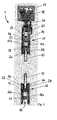
- FIG. 1 shows a receiving arrangement 1 for a wing element 10 of a mobile space separation system, wherein the wing member 10 is formed as a glass, in particular as a full glass pane.
- the wing member 10 has a rectangular shape, and the receiving of the wing member 10 via an upper edge and a lower edge, wherein the wing member 10 is in an approximately vertical arrangement in space and forms an element of the space separation system.
- the inclusion of the wing element 10 on the upper edge is carried out with a first profile element 11, and the inclusion of the wing member 10 via the lower edge by means of another profile element 12.
- the wing member 10 is shown interrupted, so that both the profile element 11 and the profile element 12 are shown in cross section together.
- the profile element 11 is connected to a trolley 18, which can be mounted on a support profile 19 on the ceiling side of the room, so that the wing member 10 can be suspended from the support section 19 and / or guided.
- the lower profile element 12 has a receiving groove 15, can run in the spring elements, which can be mounted on the bottom side in the room.
- the profile elements 11 and 12 are inventively formed by a plastic material, and the upper edge of the wing member 10 receiving profile element 11 has a first part section 11a and a second part section 11b, and the lower edge of the wing element 10 receiving profile element 12 also has a first Partial profile 12a and a second partial profile 12b.
- the sub-profiles 11a, 11b and 12a, 12b of the profile elements 11 and 12 are connected to each other by screw members 13, wherein in the second sub-profiles 11b and 12b, a through hole is provided, and in the first sub-profiles 11a and 12a, a threaded bore is provided in the screw 13 is screwed.
- the respective first partial profiles 11a and 12a each have a projection 23 which points in the direction of the oppositely disposed second partial profile 11b and 12b.
- the sub-profiles 11a, 11b, 12a and 12b on the outside arranged aperture elements 14 which can be clipped to the outside of the sub-profiles 11a, 11b, 12a and 12b.
- the glare elements 14 may be formed from an aluminum material, from a brass material and / or from a stainless steel material, and the glare elements 14 perform a decor function, in particular to cover the screw elements 13 in the plastic profile elements 11 formed.
- the profile element 11 arranged on the upper edge of the wing element 10 is connected to a retaining profile 25 in which a plurality of screw elements 27 are provided for connection between the retaining profile 25 and the first part profile 11a of the profile element 11.
- the screw members 27 may be provided at regular intervals along the edge of the wing member 10.
- a brush strip 26, which is attached to the holding profile 25, and by the between the holding profile 25 and the support section 19, a dust seal effect is achieved.
- first part profile 11a of the profile element 11 By screwing the first part profile 11a of the profile element 11 with the holding profile 25, which is made in particular of a metallic material, it has surprisingly been found that a made of plastic first and / or second part profile 11a, 11b, 12a and 12b sufficient strength may have to receive wing elements 10, in particular formed as a full glass pane, supporting.
- Sash elements 10, which are made of glass, can identify weights up to 150 kg and more, and with the above-described embodiment of the sub-profiles 11a, 11b, 12a and 12b, the possibility is created, despite a rather low strength of plastic materials, the profile elements 11 nevertheless To produce a plastic material, without these fail to function.
- FIG. 2 shows in a first partial image a detailed view of the profile element 12, which receives the wing member 10 at its lower edge.
- the profiled element 12 has a first partial profile 12a and a second partial profile 12b, and the partial profiles can with a screw 13 (see FIG. 1 ) can be screwed, which can be arranged in a through hole 17 in order to receive the wing member 10 with the sub-profiles 12a and 12b by clamping.
- a bottom 21 is shown, against which the profile element 12, the wing member 10 closes.
- the arrangement of the profile element 12 is shown on the wing element 10, wherein an opening of the profile element 12 is provided such that the receiving groove 15 is shown.
- the cross-sectional view and the side view of the profile element 12 show an arrangement of a hinge element 16 in the receiving groove 15, and the side view shows a screw connection of the hinge element 16 with the profile element 12 by means of a Gelenkelementverschraubung 22.
- the hinge member 16 can be firmly received in the receiving groove 15 be, and serves to guide a pivot pin 20 which is firmly anchored in the bottom 21.
- the pivot pin 20 forms with the hinge member 16 a hinge, so that the wing member 10 of the mobile space separation system can form a swing door.
- the rotational movement of the wing element 10 can take place about an axis of rotation 28, wherein in an embodiment of the profile element 12 made of a plastic material, the strength of the profile element 12 is sufficient to the forces in the pivot, which formed with the joint formed by the hinge member 16 and the pivot pin 20 occur, and act on the profile element 12, can be supported by this.
- the plastic of the profile element 12 may comprise a polyamide, a polyimide, a polypropylene, a polyethylene or a transparent polymethyl methacrylate.
- the plastic may in particular have a hardness of at least 65 Shore A.
- a mobile room divider system having profile elements 11 and 12 may be formed of a plastics material having a strength sufficient to retain and / or guide wing members 10 formed, for example, as all-glass panels. Both a hanging receptacle on a top side arranged profile element 11, as well as an underside receptacle by a supporting profile element 12 can be made possible, even if the profile elements 11 and 12 are made of a plastic material.
Landscapes
- Engineering & Computer Science (AREA)
- Civil Engineering (AREA)
- Structural Engineering (AREA)
- Architecture (AREA)
- Physics & Mathematics (AREA)
- Electromagnetism (AREA)
- Securing Of Glass Panes Or The Like (AREA)
- Structures Of Non-Positive Displacement Pumps (AREA)
- Harvester Elements (AREA)
- Looms (AREA)
Abstract
Description
- Die vorliegende Erfindung betrifft eine Aufnahmeanordnung für ein Flügelelement eines mobilen Raumtrennsystems mit wenigstens einem Profilelement, das zur haltenden und/oder führenden Aufnahme des Flügelelementes vorgesehen ist.
- Mobile Raumtrennsysteme können mehrere Flügelelemente aufweisen, die zur Bildung einer Trennwand in einem Raum nebeneinander angeordnet werden können. Soll die Trennwand entnommen werden, so können die Flügelelemente parallel zueinander seitlich im Raum verstaut werden, so dass die Flügelelemente nur einen geringen Raumbedarf erfordern. Die Flügelelemente können aus Holz, aus Kunststoff oder insbesondere als Ganzglasscheibe ausgebildet sein, und es sind Beschläge erforderlich, um die Ganzglasscheiben so aufzunehmen, dass diese zwischen Decke und Boden des Raumes gehalten und/oder geführt werden können. Dafür sind Profilelemente bekannt, durch die die Flügelelemente deckenseitig, insbesondere auch bodenseitig gehalten und geführt werden. Derartige Flügelelemente sind zumeist aus Leichtmetall hergestellt, und die Ganzglasscheibe wird mit den Profilelementen geklemmt, so dass weitere Führungs- oder Halteelemente an die Profilelemente angebracht werden können.
- Aus der
DE 94 19 449 U1 ist eine Aufnahmeanordnung für ein Flügelelement eines mobilen Raumtrennsystems bekannt, und es ist ein Profilelement in einem detaillierten Aufbau gezeigt, das zur haltenden und/oder führenden Aufnahme des Flügelelementes ausgebildet ist. Die Glasscheibe ist über Zwischenlagen mit dem Profilelement geklemmt aufgenommen, und das Profilelement weist ein erstes Teilprofil und ein zweites, gegenüberliegendes Teilprofil auf, und die Teilprofile klemmen die Glasscheibe über die sich gegenüberstehenden Planflächen. Zur Klemmung ist ein Schraubelement vorgesehen, mit dem die sich gegenüberstehenden Teilprofile aufeinander geschraubt werden können. Durch einen Vorsprung an einem der beiden Teilprofile entsteht eine Stützanordnung, und durch eine Zugkraft im Schraubelement werden die Backenabschnitte, die an den Teilprofilen angeformt sind und zwischen denen die Glasscheibe angeordnet ist, aufeinander gepresst. Folglich entsteht eine Klemmung der Glasscheibe, wodurch erhebliche mechanische Belastungen auf die Teilprofile der Profilelemente wirken. - Nachteilhafterweise ist die Bereitstellung der Profilelemente aus einem Lichtmetallwerkstoff nur begrenzt möglich und kostenintensiv, insbesondere sind mechanische Nachbearbeitungen des Leichtmetallwerkstoffes aufwendig.
- Es ist daher die Aufgabe der vorliegenden Erfindung, eine Aufnahmeanordnung für ein Flügelelement eines mobilen Raumtrennsystems zu schaffen, die die Nachteile des vorstehend bezeichneten Standes der Technik überwinden und die Profilelemente aufweist, die einfach und kostengünstig verfügbar sind. Insbesondere ist es die Aufgabe der vorliegenden Erfindung, eine Aufnahmeanordnung mit Profilelementen zu schaffen, die trotz einer einfachen Ausführungsform eine sichere Klemmung des Flügelelementes, insbesondere einer Glasscheibe ermöglichen.
- Diese Aufgabe wird ausgehend von einer Aufnahmeanordnung für ein Flügelelement eines mobilen Raumtrennsystems gemäß dem Oberbegriff des Anspruches 1 in Verbindung mit den kennzeichnenden Merkmalen gelöst. Vorteilhafte Weiterbildungen der Erfindung sind in den abhängigen Ansprüchen angegeben.
- Die Erfindung schließt die technische Lehre ein, dass das Profilelement aus einem Kunststoffmaterial ausgebildet ist. Dabei entsteht der Vorteil, dass das Profilelement auf einfache und kostengünstige Weise herstellbar ist, und neuerdings sind Kunststoffe verfügbar, die eine sehr hohe mechanische Belastbarkeit ermöglichen. Trotz der sehr guten mechanischen Eigenschaften ist ein Profilelement aus einem Kunststoffmaterial einfach und kostengünstig verfügbar, und sowohl die Bereitstellung eines Kunststoffmaterial-Profilelementes als auch die mechanische Weiterverarbeitung können deutlich kostengünstiger ausgeführt werden, als wenn das Profilelement aus einem Leichtmetallmaterial hergestellt ist. Ferner ergibt sich der Vorteil eines geringeren Gewichtes und einer höheren Dämpfungswirkung, wenn das oder die Profilelemente aus einem Kunststoffmaterial hergestellt sind. Ist das durch das Profilelement gehaltene und/oder geführte Flügelelement aus einer Glasscheibe gebildet, so können Klirr-Effekte auftreten, wenn die Glasscheibe mittels Leichtmetall-Materialien gehalten ist. Durch ein Glas-Kunststoff-Verbund, wie sich dieser aus der erfindungsgemäßen Ausführung der Profilelemente ergibt, entsteht eine höhere Dämpfungswirkung, so dass Klirr-Effekte vermieden werden, auch wenn das Flügelelement aus einer Glasscheibe, insbesondere aus einer Ganzglasscheibe besteht.
- Damit kann das Flügelelement mit besonderem Vorteil aus einer Glasscheibe gebildet sein, die sich als Bestandteil des mobilen Raumtrennsystems in etwa senkrechter Anordnung im Raum befindet und vorzugsweise eine rechteckige Gestalt mit einer oberen Kante und einer unteren Kante aufweist. Damit ergeben sich pro Flügelelement zwei Profilelemente, von denen eines oberseitig und eines unterseitig angeordnet ist.
- Insbesondere kann ein oberes Profilelement zur Aufnahme des Flügelelementes an der oberen Kante vorgesehen sein, welches das Flügelelement beispielsweise mit der Decke eines Raumes verbindet. Weiterhin kann ein unteres Profilelement zur Aufnahme des Flügelelementes an der unteren Kante vorgesehen sein, so dass das Flügelelement insbesondere zusätzlich über den Boden des Raumes gehalten und/oder geführt ist. Sowohl das obere als auch das untere Profilelement kann aus einem Kunststoffmaterial ausgebildet sein.
- Gemäß einer vorteilhaften Ausführungsform der Aufnahmeanordnung können die Profilelemente jeweils ein erstes Teilprofil und jeweils ein zweites Teilprofil aufweisen, zwischen denen das Flügelelement klemmbar ist, wobei wenigstens eines der Teilprofile, insbesondere jedes der Teilprofile, aus einem Kunststoffmaterial hergestellt ist. Die Teilprofile können jeweils mittels Schraubelementen miteinander verschraubbar sein, insbesondere um das Flügelelement zwischen den Teilprofilen zu klemmen.
- Vorteilhafterweise können Blendenelemente vorgesehen sein, die insbesondere seitlich an den Profilelementen anbringbar sind. Insbesondere dann, wenn die Profilelemente aus einem Kunststoffmaterial hergestellt sind, empfehlen sich Blendenelemente, die beispielsweise aus einem Aluminiummaterial, einem Messingmaterial, einem Verbundfasermaterial oder sonstigem hergestellt sind. Insbesondere können die Blendenelemente eine Dekorfunktion erfüllen, so dass für einen Betrachter nicht sichtbar ist, dass die Profilelemente, insbesondere die Teilprofile der Profilelemente, aus Kunststoff hergestellt sind. Ferner können die Schraubelemente abgedeckt werden, so dass diese ebenfalls nicht sichtbar sind, wenn die Blendenelemente auf den Teilprofilen angeordnet werden.
- Mit weiterem Vorteil kann zumindest das untere Profilelement eine Aufnahmenut aufweisen, in die zumindest ein Gelenkelement einsetzbar und insbesondere mit dem Profilelement verbindbar ist. Damit kann das Flügelelement als Drehflügel weitergebildet werden, und in der mobilen Raumtrennwand kann durch ein drehbares Flügelelement eine Tür gebildet werden. Insbesondere kann in die Aufnahmenut ein im Boden eingebrachtes Führungselement laufen, so dass die Flügelelemente nicht nur über das deckenseitige Profilelement, sondern auch über das bodenseitige Profilelement gehalten und insbesondere geführt sind. Die Aufnahmenut weist mit einer Öffnung vertikal nach unten in Richtung zum Boden eines Raumes, und im oder am Boden können Führungs- und/oder Laufschienen angeordnet sein, die in die Aufnahmenut eingreifen. Zusätzlich oder alternativ kann in der Aufnahmenut eine Dicht-Bürstenleiste eingebracht sein, so dass ein Spalt zwischen dem unteren Profilelement und dem Boden durch eine Bürstenleiste abgedichtet ist.
- Mit weiterem Vorteil kann der Kunststoff ein Polyamid, ein Polyimid, ein Polypropylen, ein Polyethylen und/oder ein insbesondere transparentes Polymethylmethacrylat umfassen. Durch die Wahl eines transparenten Polymethylmethacrylats (PMMA) können auch die Blendenelemente, die seitlich an den Teilprofilen angebracht werden können, entfallen, so dass das Profilelement als Design-Bestandteil der Aufnahmeanordnung dienen kann.
- Der Kunststoff der Profilelemente kann mit weiterem Vorteil eine Härte von wenigstens 65 Shore A aufweisen, um die gewünschte Festigkeit zu besitzen, so dass das Flügelelement, insbesondere die Glasscheibe, zwischen den Teilprofilen geklemmt aufgenommen werden kann.
- Weitere, die Erfindung verbessernde Maßnahmen werden nachstehend gemeinsam mit der Beschreibung eines bevorzugten Ausführungsbeispiels der Erfindung anhand der Figuren näher dargestellt. Es zeigt:
- Fig. 1
- eine Querschnittsansicht eines Ausführungsbeispiels einer Aufnahmeanordnung für ein Flügelelement eines mobilen Raumtrennsystems und
- Fig. 2
- eine Querschnittsansicht und eine Seitenansicht eines Profilelementes, in dem ein Gelenkelement aufgenommen ist.
-
Figur 1 zeigt eine Aufnahmeanordnung 1 für ein Flügelelement 10 eines mobilen Raumtrennsystems, wobei das Flügelelement 10 als Glasscheibe, insbesondere als Ganzglasscheibe ausgebildet ist. Das Flügelelement 10 besitzt eine Rechteckform, und die Aufnahme des Flügelelementes 10 erfolgt über eine obere Kante und eine untere Kante, wobei sich das Flügelelement 10 in einer etwa senkrechten Anordnung im Raum befindet und ein Element des Raumtrennsystems bildet. - Die Aufnahme des Flügelelementes 10 über die obere Kante erfolgt mit einem ersten Profilelement 11, und die Aufnahme des Flügelelementes 10 über die untere Kante erfolgt mittels eines weiteren Profilelementes 12. Das Flügelelement 10 ist unterbrochen dargestellt, so dass sowohl das Profilelement 11 als auch das Profilelement 12 im Querschnitt gemeinsam dargestellt sind. Das Profilelement 11 ist mit einem Rollwagen 18 verbunden, das an einem Tragprofil 19 deckenseitig des Raumes montiert werden kann, so dass das Flügelelement 10 hängend am Tragprofil 19 gehalten und/oder geführt werden kann. Das untere Profilelement 12 besitzt eine Aufnahmenut 15, in der Federelemente laufen können, die bodenseitig im Raum angebracht sein können.
- Die Profilelemente 11 und 12 sind erfindungsgemäß durch ein Kunststoffmaterial ausgebildet, und das die obere Kante des Flügelelementes 10 aufnehmende Profilelement 11 weist ein erstes Teilprofil 11a und ein zweites Teilprofil 11b auf, und das die untere Kante des Flügelelementes 10 aufnehmende Profilelement 12 weist ebenfalls ein erstes Teilprofil 12a und ein zweites Teilprofil 12b auf. Die Teilprofile 11a, 11 b und 12a, 12b der Profilelemente 11 und 12 sind jeweils durch Schraubelemente 13 miteinander verbunden, wobei in den zweiten Teilprofilen 11b und 12b ein Durchgangsloch vorgesehen ist, und in den ersten Teilprofilen 11a und 12a ist eine Gewindebohrung vorgesehen, in die das Schraubelement 13 eingeschraubt ist.
- Die jeweils ersten Teilprofile 11a und 12a besitzen jeweils einen Vorsprung 23, der in Richtung zum gegenüberliegend angeordneten zweiten Teilprofil 11b und 12b weist. Wird das Schraubelement 13 angezogen, so werden Klemmabschnitte der Teilprofile 11a und 11b bzw. 12a und 12b zangenartig aufeinander zu bewegt, und zwischen den Klemmabschnitten kann das Flügelelement 10 geklemmt werden. Zur Klemmung des Flügelelementes 10 weisen die Klemmabschnitte Zwischenlagen 24 auf, die in Vertiefungen in den Klemmabschnitten eingesetzt sind. Durch die Vertiefungen, in die die Zwischenlagen 24 eingesetzt sind, können diese bereits selbsthaltend an den Teilprofilen 11a, 11b, 12a und 12b angebracht sein, ohne dass eine stoffschlüssige Verbindung zwischen der Zwischenlage 24 und den Teilprofilen 11a, 11b, 12a und 12b notwendig wäre.
- Zur Verblendung der aus Kunststoff ausgebildeten Profilelemente 11 und 12 weisen die Teilprofile 11a, 11b, 12a und 12b außenseitig angeordnete Blendenelemente 14 auf, die an die Außenseite der Teilprofile 11a, 11b, 12a und 12b angeklipst werden können. Die Blendelemente 14 können aus einem Aluminiummaterial, aus einem Messingmaterial und/oder aus einem Edelstahlmaterial ausgebildet sein, und die Blendelemente 14 erfüllen eine Dekorfunktion, insbesondere, um die Schraubelemente 13 in den aus Kunststoff ausgebildeten Profilelementen 11 abzudecken.
- Das an der oberen Kante des Flügelelementes 10 angeordnete Profilelement 11 ist mit einem Halteprofil 25 verbunden, in dem mehrere Schraubelemente 27 zur Verbindung zwischen dem Halteprofil 25 und dem ersten Teilprofil 11a des Profilelementes 11 vorgesehen sind. Die Schraubelemente 27 können in regelmäßigen Abständen entlang der Kante des Flügelelementes 10 vorgesehen werden. Weiterhin gezeigt ist eine Bürstenleiste 26, die am Halteprofil 25 angebracht ist, und durch die zwischen dem Halteprofil 25 und dem Tragprofil 19 eine Staubdichtungswirkung erzielt wird.
- Durch die Verschraubung des ersten Teilprofils 11a des Profilelementes 11 mit dem Halteprofil 25, das insbesondere aus einem metallischen Werkstoff hergestellt ist, hat sich überraschenderweise gezeigt, dass ein aus Kunststoff hergestelltes erstes und/oder zweites Teilprofil 11a, 11b, 12a und 12b eine ausreichende Festigkeit aufweisen kann, um Flügelelemente 10, insbesondere ausgebildet als Ganzglasscheibe, tragend aufzunehmen. Flügelelemente 10, die aus Glas bestehen, können Gewichte bis zu 150 kg und mehr auf ausweisen, und mit vorstehend beschriebener Ausgestaltung der Teilprofile 11a, 11b, 12a und 12b wird die Möglichkeit geschaffen, trotz einer eher geringeren Festigkeit von Kunststoffmaterialien die Profilelemente 11 dennoch aus einem Kunststoffmaterial herzustellen, ohne dass diese die Funktion versagen.
-
Figur 2 zeigt in einem ersten Teilbild eine Detailansicht des Profilelementes 12, welches das Flügelelement 10 an seiner unteren Kante aufnimmt. Das Profilelement 12 besitzt ein erstes Teilprofil 12a und ein zweites Teilprofil 12b, und die Teilprofile können mit einem Schraubelement 13 (sieheFigur 1 ) verschraubt werden, das in einem Durchgangsloch 17 angeordnet werden kann, um mit den Teilprofilen 12a und 12b das Flügelelement 10 klemmend aufzunehmen. Unterseitig des Profilelementes 12 ist ein Boden 21 gezeigt, gegen den das Profilelement 12 das Flügelelement 10 abschließt. - In der rechten Teilansicht ist die Anordnung des Profilelementes 12 am Flügelelement 10 gezeigt, wobei ein Aufbruch des Profilelementes 12 derart vorgesehen ist, dass die Aufnahmenut 15 dargestellt ist.
- Die Querschnittsansicht und die Seitenansicht des Profilelementes 12 zeigen eine Anordnung eines Gelenkelementes 16 in der Aufnahmenut 15, und die Seitenansicht zeigt eine Verschraubung des Gelenkelementes 16 mit dem Profilelement 12 mittels einer Gelenkelementverschraubung 22. Das Gelenkelement 16 kann in der Aufnahmenut 15 fest aufgenommen sein, und dient zur Führung eines Gelenkzapfens 20, das im Boden 21 fest verankert ist. Der Gelenkzapfen 20 bildet mit dem Gelenkelement 16 ein Drehgelenk, so dass das Flügelelement 10 des mobilen Raumtrennsystems eine Drehflügeltür bilden kann. Die Drehbewegung des Flügelelementes 10 kann um eine Drehachse 28 erfolgen, wobei bei einer Ausbildung des Profilelementes 12 aus einem Kunststoffmaterial die Festigkeit des Profilelementes 12 hinreichend ist, um die Kräfte im Drehgelenk, die die mit dem durch das Gelenkelement 16 und dem Gelenkzapfen 20 gebildeten Drehgelenk auftreten, und auf das Profilelement 12 wirken, von diesem getragen werden können. Beispielsweise kann der Kunststoff des Profilelementes 12 ein Polyamid, ein Polyimid, ein Polypropylen, ein Polyethylen oder ein transparentes Polymethylmethacrylat umfassen. Der Kunststoff kann insbesondere eine Härte von wenigstens 65 Shore A aufweisen.
- Im Ergebnis kann ein mobiles Raumtrennsystem mit Profilelementen 11 und 12 aus einem Kunststoffmaterial gebildet werden, die eine Festigkeit aufweisen, die hinreichend ist, um Flügelelemente 10, die beispielsweise als Ganzglasscheiben gebildet sind, haltend und/oder führend aufzunehmen. Sowohl eine hängende Aufnahme über ein oberseitig angeordnetes Profilelement 11, als auch eine unterseitige Aufnahme durch ein stützendes Profilelement 12 kann ermöglicht werden, auch wenn die Profilelemente 11 und 12 aus einem Kunststoffmaterial hergestellt sind.
- Die Erfindung beschränkt sich in ihrer Ausführung nicht auf das vorstehend angegebene bevorzugte Ausführungsbeispiel. Vielmehr ist eine Anzahl von Varianten denkbar, welche von der dargestellten Lösung auch bei grundsätzlich anders gearteten Ausführungen Gebrauch macht. Sämtliche aus den Ansprüchen, der Beschreibung oder den Zeichnungen hervorgehenden Merkmale und/oder Vorteile, einschließlich konstruktiver Einzelheiten oder räumliche Anordnungen, können sowohl für sich als auch in den verschiedensten Kombinationen erfindungswesentlich sein.
-
- 1
- Aufnahmeanordnung
- 10
- Flügelelement
- 11
- Profilelement
- 11a
- erstes Teilprofil
- 11b
- zweites Teilprofil
- 12
- Profilelement
- 12a
- erstes Teilprofil
- 12b
- zweites Teilprofil
- 13
- Schraubelement
- 14
- Blendenelement
- 15
- Aufnahmenut
- 16
- Gelenkelement
- 17
- Durchgangsloch
- 18
- Rollwagen
- 19
- Tragprofil
- 20
- Gelenkzapfen
- 21
- Boden
- 22
- Gelenkelementverschraubung
- 23
- Vorsprung
- 24
- Zwischenlage
- 25
- Halteprofil
- 26
- Bürstenleiste
- 27
- Schraubelement
- 28
- Drehachse
Claims (10)
- Aufnahmeanordnung (1) für ein Flügelelement (10) eines mobilen Raumtrennsystems mit wenigstens einem Profilelement (11, 12), das zur haltenden und/oder führenden Aufnahme des Flügelelementes (10) vorgesehen ist, dadurch gekennzeichnet, dass das Profilelement (11, 12) aus einem Kunststoffmaterial ausgebildet ist.
- Aufnahmeanordnung (1) nach Anspruch 0, dadurch gekennzeichnet, dass das Flügelelement (10) aus einer Glasscheibe gebildet ist, die sich als Bestandteil des mobilen Raumtrennsystems in etwa senkrechter Anordnung befindet und vorzugsweise eine rechteckige Gestalt mit einer oberen Kante und einer unteren Kante aufweist.
- Aufnahmeanordnung (1) nach Anspruch 0 oder 2, dadurch gekennzeichnet, dass ein oberes Profilelement (11) zur Aufnahme des Flügelelementes (10) an der oberen Kante vorgesehen ist, wobei das obere Profilelement (11) aus einem Kunststoffmaterial ausgebildet ist.
- Aufnahmeanordnung (1) nach einem der vorgenannten Ansprüche, dadurch gekennzeichnet, dass ein unteres Profilelement (12) zur Aufnahme des Flügelelementes (10) an der unteren Kante vorgesehen ist, wobei das untere Profilelement (12) aus einem Kunststoffmaterial ausgebildet ist.
- Aufnahmeanordnung (1) nach einem der vorgenannten Ansprüche, dadurch gekennzeichnet, dass die Profilelemente (11, 12) jeweils ein erstes Teilprofil (11a, 12a) und jeweils ein zweites Teilprofil (11b, 12b) aufweisen, zwischen denen das Flügelelement (10) klemmbar ist, wobei wenigstens eines der Teilprofile (11a, 12a, 11 b, 12b), insbesondere jedes der Teilprofile (11a, 12a, 11b, 12b), aus einem Kunststoffmaterial hergestellt ist.
- Aufnahmeanordnung (1) nach einem der vorgenannten Ansprüche, dadurch gekennzeichnet, dass die Teilprofile (11a, 12a, 11 b, 12b) jeweils mittels Schraubelementen (13) miteinander verschraubbar sind, insbesondere um das Flügelelement (10) zwischen den Teilprofilen (11a, 12a, 11 b, 12b) zu klemmen.
- Aufnahmeanordnung (1) nach einem der vorgenannten Ansprüche, dadurch gekennzeichnet, dass Blendenelemente (14) vorgesehen sind, die insbesondere seitlich an den Profilelementen (11, 12) anbringbar sind.
- Aufnahmeanordnung (1) nach einem der vorgenannten Ansprüche, dadurch gekennzeichnet, dass zumindest das untere Profilelement (12) eine Aufnahmenut (15) aufweist, in die zumindest ein Gelenkelement (16) einsetzbar und insbesondere mit dem Profilelement (12) verbindbar ist.
- Aufnahmeanordnung (1) nach einem der vorgenannten Ansprüche, dadurch gekennzeichnet, dass der Kunststoff ein Polyamid, ein Polypropylen, ein Polyethylen oder ein transparentes Polymethylmethacrylat umfasst.
- Aufnahmeanordnung (1) nach einem der vorgenannten Ansprüche, dadurch gekennzeichnet, dass der Kunststoff der Profilelemente (11, 12) eine Härte von wenigstens 65 Shore A aufweist.
Applications Claiming Priority (1)
| Application Number | Priority Date | Filing Date | Title |
|---|---|---|---|
| DE202011050186U DE202011050186U1 (de) | 2011-05-19 | 2011-05-19 | Aufnahmeanordnung für ein Flügelelement eines mobilen Raumtrennsystems |
Publications (2)
| Publication Number | Publication Date |
|---|---|
| EP2525008A2 true EP2525008A2 (de) | 2012-11-21 |
| EP2525008A3 EP2525008A3 (de) | 2017-05-17 |
Family
ID=44357080
Family Applications (1)
| Application Number | Title | Priority Date | Filing Date |
|---|---|---|---|
| EP12002497.1A Withdrawn EP2525008A3 (de) | 2011-05-19 | 2012-04-05 | Aufnahmeanordnung für ein Flügelelement eines mobilen Raumtrennsystems |
Country Status (4)
| Country | Link |
|---|---|
| EP (1) | EP2525008A3 (de) |
| CN (1) | CN102808466A (de) |
| DE (1) | DE202011050186U1 (de) |
| TW (1) | TW201247989A (de) |
Citations (1)
| Publication number | Priority date | Publication date | Assignee | Title |
|---|---|---|---|---|
| DE9419449U1 (de) | 1994-12-03 | 1995-02-16 | Dorma Gmbh + Co. Kg, 58256 Ennepetal | Türschiene für eine Ganzglastür |
Family Cites Families (10)
| Publication number | Priority date | Publication date | Assignee | Title |
|---|---|---|---|---|
| JPS5443047U (de) * | 1977-08-26 | 1979-03-23 | ||
| AT379184B (de) * | 1984-01-17 | 1985-11-25 | Meusburger Walter | Trennwand mit horizontal verschiebbaren scheiben |
| US4914888A (en) * | 1988-08-29 | 1990-04-10 | Capitol Glass & Aluminum Corporation | Support frame for glass panel |
| CN2117450U (zh) * | 1992-03-05 | 1992-09-30 | 李�浩 | 快装门窗玻璃用塑料框 |
| AU2408597A (en) * | 1996-04-26 | 1997-11-19 | Kaneka Corporation | Light-controllable heat insulating window |
| CN2293631Y (zh) * | 1997-06-06 | 1998-10-07 | 邵英弟 | 复合层推拉门窗型材 |
| DE29718854U1 (de) * | 1997-10-23 | 1998-01-02 | Sks Stakusit Kunststoff Gmbh | Profilrahmen, insbesondere U-Profilrahmen zur Halterung von Flächenelementen wie Glasscheiben, Kunststoffplatten o.dgl. |
| CN2403873Y (zh) * | 1999-12-29 | 2000-11-01 | 张利 | 一种平移手动门 |
| CN1207482C (zh) * | 2003-01-21 | 2005-06-22 | 徐晶 | 高性能塑料推拉门窗 |
| WO2007048266A1 (de) * | 2005-10-27 | 2007-05-03 | Kaba Gilgen Ag | Glasflügel für türen, tore, wände und fenster |
-
2011
- 2011-05-19 DE DE202011050186U patent/DE202011050186U1/de not_active Expired - Lifetime
-
2012
- 2012-04-05 EP EP12002497.1A patent/EP2525008A3/de not_active Withdrawn
- 2012-05-09 TW TW101116468A patent/TW201247989A/zh unknown
- 2012-05-18 CN CN2012101568728A patent/CN102808466A/zh active Pending
Patent Citations (1)
| Publication number | Priority date | Publication date | Assignee | Title |
|---|---|---|---|---|
| DE9419449U1 (de) | 1994-12-03 | 1995-02-16 | Dorma Gmbh + Co. Kg, 58256 Ennepetal | Türschiene für eine Ganzglastür |
Also Published As
| Publication number | Publication date |
|---|---|
| TW201247989A (en) | 2012-12-01 |
| CN102808466A (zh) | 2012-12-05 |
| DE202011050186U1 (de) | 2011-07-05 |
| EP2525008A3 (de) | 2017-05-17 |
Similar Documents
| Publication | Publication Date | Title |
|---|---|---|
| EP1560997B1 (de) | Trennwand | |
| EP3754128A1 (de) | Akustikpaneel mit versetzten nuten | |
| EP2618706B1 (de) | Duschwand mit einer schiebetür | |
| EP3034735B1 (de) | Schiebewandsystem mit mindestens einem Türflügelelement mit einer Glasscheibe und Verfahren zum Befestigen der Glasscheibe im Schiebewandsystem | |
| EP2405093B1 (de) | Modulare Brandschutzverglasung | |
| WO2005083217A1 (de) | Befestigunsvorrichtung für eine gleit- oder führungsschiene | |
| EP2525008A2 (de) | Aufnahmeanordnung für ein Flügelelement eines mobilen Raumtrennsystems | |
| DE202016101061U1 (de) | Halteklemme für eine Geländerplatte und vorzugsweise für eine Ganzglasglasgeländerplatte | |
| DE202015008576U1 (de) | Profilanordnung und Raumabtrennung | |
| DE10319278B4 (de) | Fassadenelement zum Verkleiden einer Gebäudewand | |
| DE29724007U1 (de) | Türsystem | |
| DE10120889B4 (de) | Glasprallwand | |
| DE102004010862B4 (de) | Doppelverglasung an einem Innenausbauteil eines Gebäudes, insbesondere einer Trennwand für den Innenausbau | |
| EP2492424A2 (de) | Verbindungsvorrichtung einer Trennwand, insbesondere Duschtrennwand | |
| EP3034739A1 (de) | Schiebewandsystem mit optimierter Dichtung | |
| EP2735667A1 (de) | Fassaden-Tragkonstruktion mit Verschlussprofil für eine Horizontalfuge | |
| AT413411B (de) | Trennwandsystem bestehend aus rahmenlosen glastafeln, sowie halteclipse für ein trennwandsystem | |
| AT521978B1 (de) | Türanlage für ein trennwandsystem | |
| DE202006012093U1 (de) | Halterungsvorrichtung für Flächenelemente | |
| EP3034743B1 (de) | Schiebewandsystem mit Sicherungsvorrichtung | |
| DE19801635A1 (de) | Scharniergelenk für Drehflügeltore | |
| DE102009027450B4 (de) | Schiebetüranlage | |
| EP3064699A1 (de) | Fenster oder Tür sowie Verfahren zum Herstellen desselben | |
| WO2024211936A1 (de) | Profil für wenigstens ein abdeckelement | |
| EP3034741A1 (de) | Schiebewandsystem mit verbessertem akustischem Verhalten |
Legal Events
| Date | Code | Title | Description |
|---|---|---|---|
| PUAI | Public reference made under article 153(3) epc to a published international application that has entered the european phase |
Free format text: ORIGINAL CODE: 0009012 |
|
| AK | Designated contracting states |
Kind code of ref document: A2 Designated state(s): AL AT BE BG CH CY CZ DE DK EE ES FI FR GB GR HR HU IE IS IT LI LT LU LV MC MK MT NL NO PL PT RO RS SE SI SK SM TR |
|
| AX | Request for extension of the european patent |
Extension state: BA ME |
|
| RAP1 | Party data changed (applicant data changed or rights of an application transferred) |
Owner name: DORMA DEUTSCHLAND GMBH |
|
| PUAL | Search report despatched |
Free format text: ORIGINAL CODE: 0009013 |
|
| RAP1 | Party data changed (applicant data changed or rights of an application transferred) |
Owner name: DORMAKABA DEUTSCHLAND GMBH |
|
| AK | Designated contracting states |
Kind code of ref document: A3 Designated state(s): AL AT BE BG CH CY CZ DE DK EE ES FI FR GB GR HR HU IE IS IT LI LT LU LV MC MK MT NL NO PL PT RO RS SE SI SK SM TR |
|
| AX | Request for extension of the european patent |
Extension state: BA ME |
|
| RIC1 | Information provided on ipc code assigned before grant |
Ipc: E06B 3/54 20060101ALI20170411BHEP Ipc: E06B 3/02 20060101ALI20170411BHEP Ipc: E04B 2/82 20060101AFI20170411BHEP |
|
| STAA | Information on the status of an ep patent application or granted ep patent |
Free format text: STATUS: THE APPLICATION HAS BEEN WITHDRAWN |
|
| 18W | Application withdrawn |
Effective date: 20171114 |