EP2525003A2 - Adapter for cleaning a siphon or drainage pipe connected to a floor drainage tray, in particular a shower tray - Google Patents
Adapter for cleaning a siphon or drainage pipe connected to a floor drainage tray, in particular a shower tray Download PDFInfo
- Publication number
- EP2525003A2 EP2525003A2 EP12165166A EP12165166A EP2525003A2 EP 2525003 A2 EP2525003 A2 EP 2525003A2 EP 12165166 A EP12165166 A EP 12165166A EP 12165166 A EP12165166 A EP 12165166A EP 2525003 A2 EP2525003 A2 EP 2525003A2
- Authority
- EP
- European Patent Office
- Prior art keywords
- pipe socket
- adapter according
- adapter
- socket
- pipe
- Prior art date
- Legal status (The legal status is an assumption and is not a legal conclusion. Google has not performed a legal analysis and makes no representation as to the accuracy of the status listed.)
- Granted
Links
- 238000004140 cleaning Methods 0.000 title claims description 6
- 238000007789 sealing Methods 0.000 claims abstract description 13
- 230000002093 peripheral effect Effects 0.000 claims description 6
- 230000003014 reinforcing effect Effects 0.000 claims description 4
- IHQKEDIOMGYHEB-UHFFFAOYSA-M sodium dimethylarsinate Chemical class [Na+].C[As](C)([O-])=O IHQKEDIOMGYHEB-UHFFFAOYSA-M 0.000 claims description 2
- 239000003518 caustics Substances 0.000 description 3
- 230000000694 effects Effects 0.000 description 3
- 230000006978 adaptation Effects 0.000 description 1
- 231100001261 hazardous Toxicity 0.000 description 1
- 238000001746 injection moulding Methods 0.000 description 1
- 238000003780 insertion Methods 0.000 description 1
- 230000037431 insertion Effects 0.000 description 1
- 239000007788 liquid Substances 0.000 description 1
- 239000000463 material Substances 0.000 description 1
- 239000002245 particle Substances 0.000 description 1
- 239000004033 plastic Substances 0.000 description 1
- 239000004575 stone Substances 0.000 description 1
- XLYOFNOQVPJJNP-UHFFFAOYSA-N water Substances O XLYOFNOQVPJJNP-UHFFFAOYSA-N 0.000 description 1
Images

Classifications
-
- E—FIXED CONSTRUCTIONS
- E03—WATER SUPPLY; SEWERAGE
- E03C—DOMESTIC PLUMBING INSTALLATIONS FOR FRESH WATER OR WASTE WATER; SINKS
- E03C1/00—Domestic plumbing installations for fresh water or waste water; Sinks
- E03C1/12—Plumbing installations for waste water; Basins or fountains connected thereto; Sinks
- E03C1/30—Devices to facilitate removing of obstructions in waste-pipes or sinks
- E03C1/304—Devices to facilitate removing of obstructions in waste-pipes or sinks using fluid under pressure
- E03C1/308—Devices to facilitate removing of obstructions in waste-pipes or sinks using fluid under pressure by means of a pumping device
-
- E—FIXED CONSTRUCTIONS
- E03—WATER SUPPLY; SEWERAGE
- E03F—SEWERS; CESSPOOLS
- E03F5/00—Sewerage structures
- E03F5/04—Gullies inlets, road sinks, floor drains with or without odour seals or sediment traps
- E03F5/041—Accessories therefor
Definitions
- a suction cup (colloquially referred to as Pümpel) is used.
- a suction cup is known to consist of a rubber bell, which is usually attached to the end of a wooden rod.
- An advantageous embodiment of the adapter according to the invention is characterized in that the adapter plate is provided on the underside with a tubular connecting piece, which is connected liquid-tight and axially adjustable with the pipe socket or connectable.
- the tubular connecting piece and the pipe socket in this case together form a telescopic tube.
- This embodiment allows optimal adaptation of the adapter to differently deep running gutters, in particular shower channels. A different gutter depth can result from differently dimensioned gutter bodies and / or differently thick floor tiles or natural stone slabs which overlap a circumferential flange of the gutter body.
- a further embodiment of the adapter according to the invention with respect to the preferred telescopic design provides that the socket-like connecting portion of the pipe socket and the end portion of the connecting piece insertable therein have oval cross-sections.
- the adapter according to the invention is characterized by a high breaking strength with comparatively low weight or material consumption, if according to another preferred Design on the underside of the adapter plate reinforcing ribs are formed.
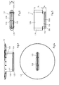
- the adapter 1 comprises an adapter plate 1.2, which has an opening in the pipe socket 1.1 opening 1.21.
- the opening 1.21 is formed substantially slit-shaped.
- the adapter plate 1.2 may be integrally formed at the upper end of the pipe socket 1.1.
- the pipe socket 1.1 and the adapter plate 1.2 are formed as separate parts, wherein on the adapter plate 1.2 on the underside a tubular connecting piece 1.22 is attached, which is liquid-tight and axially adjustable with the pipe socket 1.1 connectable.
- the connecting piece 1.22 of the adapter plate 1.2 is inserted for this purpose in the pipe socket 1.1.
- the pipe socket 1.1 has a sleeve-like connecting portion 1.13, in which an end portion of 1.221 of the connecting piece 1.22 can be inserted.
- the sleeve-like connecting portion 1.13 of the pipe socket 1.2 and the end portion 1.221 of the connecting piece 1.22 which can be inserted therein also have essentially oval cross-sections.
- the connecting piece 1.22 of the adapter plate 1.2 has at its the pipe socket 1.1 associated end inside also a grid-shaped cross bracing 1.26.
- a grid-shaped cross bracing 1.26 In the FIGS. 1 and 3 It can be seen that at the end of the connecting piece 1.22 on the outside a beveled peripheral edge 1.27 or circumferential chamfer 1.27 is formed.
- the embodiment of the adapter according to the invention is not limited to the embodiment shown in the drawing. On the contrary, numerous variants are conceivable which make use of the invention specified in the appended claims, even if the design deviates from the exemplary embodiment.
- the pipe socket 1.1 and the connecting piece 1.22 can also be made substantially circular cylindrical, wherein the pipe socket 1.1 may optionally be integrally formed on the adapter plate 1.2.
Landscapes
- Engineering & Computer Science (AREA)
- Health & Medical Sciences (AREA)
- Life Sciences & Earth Sciences (AREA)
- Hydrology & Water Resources (AREA)
- Public Health (AREA)
- Water Supply & Treatment (AREA)
- Environmental & Geological Engineering (AREA)
- Sink And Installation For Waste Water (AREA)
Abstract
Description
Die Erfindung betrifft einen Adapter zur Reinigung eines an einer Bodenablaufrinne, insbesondere Duschrinne angeschlossenen Siphons oder Ablaufrohres. Ferner betrifft die Erfindung die Verwendung eines solchen Adapters in Kombination mit einer Saugglocke.The invention relates to an adapter for cleaning a connected to a floor drainage channel, in particular shower channel siphon or drain pipe. Furthermore, the invention relates to the use of such an adapter in combination with a suction cup.
In sanitären Ablaufrohren bzw. Siphons von Waschbecken, Badewannen und Spülen können beispielsweise durch Schmutzpartikel, Haare und andere Ablagerungen Verstopfungen auftreten. Zur Beseitigung solcher Verstopfungen wird üblicherweise eine Saugglocke (umgangssprachlich auch als Pümpel bezeichnet) verwendet. Eine Saugglocke besteht bekanntermaßen aus einer Gummiglocke, die üblicherweise am Ende eines Holzstabes angebracht ist. Indem die Saugglocke abdichtend auf der Einlauföffnung des verstopften Ablaufrohres angeordnet und sodann sowohl Über- als auch Unterdruck erzeugt wird, können Verstopfungen in dem Ablaufrohr bzw. Siphon beseitigt werden. Alternativ oder ergänzend werden auch ätzende Rohrreinigungsmittel in flüssiger oder körniger Form verwendet, um Verstopfungen in sanitären Ablaufrohren bzw. Siphons aufzulösen.In sanitary drain pipes or siphons of sinks, bathtubs and sinks, for example, by dirt particles, hair and other deposits blockages occur. To eliminate such blockages usually a suction cup (colloquially referred to as Pümpel) is used. A suction cup is known to consist of a rubber bell, which is usually attached to the end of a wooden rod. By the suction cup sealingly arranged on the inlet opening of the plugged drain pipe and then both positive and negative pressure is generated, blockages in the drain pipe or siphon can be eliminated. Alternatively or additionally, corrosive pipe cleaners are used in liquid or granular form to dissolve blockages in sanitary drainage pipes or siphons.
Viele existierende sanitäre Bodenabläufe, insbesondere Ablaufrinnen und Duschrinnen sind jedoch relativ lang und schmal ausgebildet. Eine handelsübliche Saugglocke (Pümpel) lässt sich bei solchen Bodenabläufen in der Regel nicht wirksam anwenden, da die Gummiglocke aufgrund ihrer Abmessungen die Einlauföffnung des Ablaufrohres bzw. Siphons nicht dichtend überdeckt. Um Verstopfungen in solchen Bodenabläufen zu beseitigen, können zwar gegebenenfalls ätzende Rohrreinigungsmittel verwendet werden, jedoch sind diese Rohrreinigungsmittel aufgrund ihrer ätzenden Wirkung für den Anwender nicht ungefährlich, relativ teuer und belasten zudem in vielen Fällen die Umwelt.However, many existing sanitary floor drains, in particular gutters and shower channels are relatively long and narrow. A commercial suction bell (Pümpel) can not be in such Bodenabläufen usually Apply effectively, since the rubber bell does not cover the inlet opening of the drain pipe or siphon due to their dimensions. Although caustic pipe cleaners may be used to remove clogs in such floor drains, these caustic cleaners are not hazardous to the user due to their caustic effect, are relatively expensive, and in many cases pollute the environment.
Der vorliegenden Erfindung liegt die Aufgabe zugrunde, eine vergleichsweise kostengünstige Vorrichtung bereitzustellen, mittels der sich Verstopfungen in einem Ablaufrohr bzw. Siphon einer Duschrinne oder schmalen Bodenablaufrinne unter Verwendung einer Saugglocke wirksam beseitigen lassen.The present invention has for its object to provide a comparatively inexpensive device by means of which can be effectively eliminate blockages in a drain pipe or siphon of a shower channel or narrow floor drainage channel using a suction cup.
Diese Aufgabe wird durch einen Adapter mit den Merkmalen des Anspruchs 1 gelöst.This object is achieved by an adapter with the features of claim 1.
Der erfindungsgemäße Adapter umfasst im Wesentlichen einen in einen Ablaufstutzen der Bodenablaufrinne einsteckbaren Rohrstutzen, dessen Mantelfläche als Dichtfläche gegenüber dem Ablaufstutzen wirkt oder mit einem Dichtring versehen ist, und eine Adapterplatte, die den Rohrstutzen außenseitig radial überragt, eine in den Rohrstutzen mündende Öffnung aufweist und mit dem Rohrstutzen flüssigkeitsdicht verbunden ist.The adapter according to the invention essentially comprises a pipe socket which can be inserted into a drain neck of the floor drainage channel and whose lateral surface acts as a sealing surface opposite the drain pipe or is provided with a sealing ring, and an adapter plate which radially projects beyond the pipe socket, has an opening opening into the pipe socket and with the pipe socket is connected liquid-tight.
Der Rohrstutzen des erfindungsgemäßen Adapters lässt sich rohraußenseitig abdichtend in den Ablaufstutzen der Bodenablaufrinne bzw. Duschrinne einstecken. Anschließend lässt sich die Gummiglocke einer handelsüblichen Saugglocke (Pümpel) druck- bzw. saugdicht auf die Adapterplatte des erfindungsgemäßen Adapters aufsetzen und niederdrücken. Erforderlichenfalls wird daraufhin dem Ablaufbereich noch zusätzliches Wasser zugeführt, so dass beim anschließenden kurzen Anheben der Gummiglocke der verstopfte Ablauf geflutet wird. Durch zügiges Auf- und Abbewegen des Saugglockenstabes wird mittels der Saugglocke ein Unterdruck erzeugt, durch den sich eine Verstopfung in dem an der Ablaufrinne bzw. Duschrinne angeschlossenen Ablaufrohr oder Siphon lösen lässt, so dass sich die die Verstopfung verursachenden Haare und/oder Ablagerungen in Richtung eines einen größeren Innendurchmesser aufweisenden Abschnitts der Ablaufleitung drücken lassen.The pipe socket of the adapter according to the invention can be inserted sealingly outside into the outlet pipe of the floor drainage channel or shower channel. Subsequently, the rubber bell of a commercial suction bell (Pümpel) pressure or suction tight on the adapter plate of the Put on the adapter and press down. If necessary, additional water is then added to the drain area, so that the clogged drain is flooded during the subsequent short lifting of the rubber bell. By rapid movement up and down of the Saugglockenstabes a vacuum is generated by means of the suction cup, through which a blockage can be solved in the attached to the gutter or shower drain pipe or siphon, so that the clogging causing hair and / or deposits in the direction let press a portion of the drain pipe having a larger inner diameter.
Der erfindungsgemäße Adapter lässt sich relativ kostengünstig, vorzugsweise durch Spritzgießen aus Kunststoff herstellen.The adapter according to the invention can be produced relatively inexpensively, preferably by injection molding of plastic.
Eine vorteilhafte Ausgestaltung des erfindungsgemäßen Adapters ist dadurch gekennzeichnet, dass die Adapterplatte unterseitig mit einem rohrförmigen Verbindungsstutzen versehen ist, der flüssigkeitsdicht und axial verstellbar mit dem Rohrstutzen verbunden bzw. verbindbar ist. Der rohrförmige Verbindungsstutzen und der Rohrstutzen bilden in diesem Fall zusammen ein teleskopartiges Rohr. Diese Ausgestaltung ermöglicht eine optimale Anpassung des Adapters an unterschiedlich tief ausgeführte Bodenablaufrinnen, insbesondere Duschrinnen. Eine unterschiedliche Rinnentiefe kann sich durch unterschiedlich dimensionierte Rinnenkörper und/oder durch unterschiedlich dicke Bodenfliesen oder Natursteinplatten, welche einen umlaufenden Flansch des Rinnenkörpers überlappen, ergeben.An advantageous embodiment of the adapter according to the invention is characterized in that the adapter plate is provided on the underside with a tubular connecting piece, which is connected liquid-tight and axially adjustable with the pipe socket or connectable. The tubular connecting piece and the pipe socket in this case together form a telescopic tube. This embodiment allows optimal adaptation of the adapter to differently deep running gutters, in particular shower channels. A different gutter depth can result from differently dimensioned gutter bodies and / or differently thick floor tiles or natural stone slabs which overlap a circumferential flange of the gutter body.
Der Verbindungsstutzen weist dabei vorzugsweise an seinem dem Rohrstutzen zugeordneten Ende einen Dichtring auf. Hierdurch wird bei einfach auszuführender axialer Verstellbarkeit des Verbindungsstutzens relativ zu dem in den Ablaufstutzen der Bodenablaufrinne (Duschrinne) einsteckbaren Rohrstutzen eine zuverlässige Dichtwirkung zwischen Verbindungsstutzen und Rohrstutzen des Adapters erzielt.The connection piece preferably has a sealing ring at its end associated with the pipe socket. As a result, a reliable sealing effect between the connecting piece and the pipe socket of the adapter is achieved with easy to be carried out axial adjustability of the connecting piece relative to the insertable into the outlet nozzle of the floor drainage channel (shower channel) pipe socket.
Eine axiale Verstellbarkeit des Verbindungsstutzens relativ zu dem Rohrstutzen und eine zuverlässige Dichtwirkung zwischen Verbindungsstutzen und Rohrstutzen lassen sich vorteilhaft insbesondere dadurch realisieren, dass der Rohrstutzen des erfindungsgemäßen Adapters nach einer bevorzugten Ausgestaltung einen muffenartigen Verbindungsabschnitt aufweist, in den ein Endabschnitt des Verbindungsstutzens einsteckbar ist.An axial adjustability of the connecting piece relative to the pipe socket and a reliable sealing effect between connecting pieces and pipe socket can be advantageously realized in particular by the fact that the pipe socket of the adapter according to the invention comprises a sleeve-like connecting portion according to a preferred embodiment, in which an end portion of the connecting piece can be inserted.
Eine weitere bevorzugte Ausgestaltung des erfindungsgemäßen Adapters besteht darin, dass das dem Ablaufstutzen der Bodenablaufrinne (Duschrinne) zugeordnete Ende des Rohrstutzens einen oval ausgebildeten Querschnitt aufweist. Diese Ausgestaltung des erfindungsgemäßen Adapters ist beispielsweise für besonders schmal ausgebildete Bodenablauf- oder Duschrinnen bestimmt, deren Ablaufstutzen einen oval ausgebildeten Querschnitt aufweist, um trotz schmaler Rinnenbreite gleichwohl eine hohe Ablaufleistung der Bodenablauf- bzw. Duschrinne zu ermöglichen. Die Breite des ovalen Endes des Rohrstutzens, d.h. das kürzere Außenmaß des ovalen Rohrstutzens liegt beispielsweise im Bereich von ca. 4 cm bis ca. 1,5 cm, insbesondere im Bereich von ca. 3 cm bis ca. 1,5 cm.A further preferred embodiment of the adapter according to the invention is that the end of the pipe socket assigned to the outlet connection of the floor drainage channel (shower channel) has an oval cross-section. This embodiment of the adapter according to the invention is intended, for example, for particularly narrow floor drainage channels or shower channels, whose outlet nozzle has an oval cross-section, in order nevertheless to allow a high drainage capacity of the floor drain or shower channel despite the narrow channel width. The width of the oval end of the pipe socket, ie the shorter outer dimension of the oval pipe socket is for example in the range of about 4 cm to about 1.5 cm, in particular in the range of about 3 cm to about 1.5 cm.
In diesem Zusammenhang sieht eine weitere Ausgestaltung des erfindungsgemäßen Adapters in Bezug auf dessen bevorzugte teleskopartige Ausgestaltung vor, dass der muffenartige Verbindungsabschnitt des Rohrstutzens und der darin einsteckbare Endabschnitt des Verbindungsstutzens oval ausgebildete Querschnitte aufweisen.In this context, a further embodiment of the adapter according to the invention with respect to the preferred telescopic design provides that the socket-like connecting portion of the pipe socket and the end portion of the connecting piece insertable therein have oval cross-sections.
Eine weitere vorteilhafte Ausgestaltung besteht hinsichtlich schmaler Bodenablauf- oder Duschrinnen, deren Ablaufstutzen einen oval ausgebildeten Querschnitt aufweist, darin, dass das dem Ablaufstutzen zugeordnete Ende des Rohrstutzens und der muffenartige Verbindungsabschnitt des Rohrstutzens im Wesentlichen stufenlos in einander übergehende Breitseiten aufweisen, und dass der muffenartige Verbindungsabschnitt das dem Ablaufstutzen der Bodenablauf- bzw. Duschrinne zugeordnete Ende des Rohrstutzens an dessen Schmalseiten stufenförmig überragt. Hierdurch kann der begrenzte Raum in der schmalen Rinne optimal zum Einsatz eines relativ breiten Rohrstutzens genutzt und damit eine relativ hohe Saugwirkung mittels einer Saugglocke zur Reinigung des an der Rinne angeschlossenen Ablaufrohres bzw. Siphons erzielt werden.A further advantageous embodiment is in terms of narrow floor drain or shower channels, the drain pipe has an oval cross-section, in that the outlet spigot associated end of the pipe socket and the socket-like connecting portion of the pipe socket have substantially continuous in each other passing broad sides, and that the sleeve-like connecting portion the end of the pipe socket assigned to the discharge nozzle of the floor drain or shower channel projects in a stepped manner on its narrow sides. As a result, the limited space in the narrow channel optimally used to use a relatively wide pipe socket and thus a relatively high suction by means of a suction cup for cleaning the drain pipe connected to the gutter or siphon can be achieved.
Um einen relativ großen axialen Verstellbereich des teleskopartig ausgebildeten Adapters zu erreichen, sieht eine weitere bevorzugte Ausgestaltung der Erfindung vor, dass die Höhe des muffenartigen Verbindungsabschnitts mindestens das Doppelte der Höhe des dem Ablaufstutzen der Bodenablaufrinne zugeordneten Endes des Rohrstutzens beträgt.In order to achieve a relatively large axial adjustment range of the telescopically formed adapter, a further preferred embodiment of the invention provides that the height of the sleeve-like connecting portion is at least twice the height of the outlet nozzle of the floor drain associated end of the pipe socket.
Der erfindungsgemäße Adapter zeichnet sich durch eine hohe Bruchfestigkeit bei vergleichsweise geringem Gewicht bzw. Materialverbrauch aus, wenn nach einer weiteren bevorzugten Ausgestaltung an der Unterseite der Adapterplatte Verstärkungsrippen ausgebildet sind.The adapter according to the invention is characterized by a high breaking strength with comparatively low weight or material consumption, if according to another preferred Design on the underside of the adapter plate reinforcing ribs are formed.
Die Stabilität des erfindungsgemäßen Adapters wird nach einer weiteren bevorzugten Ausgestaltung dadurch verbessert, dass der Rohrstutzen an seinem in den Ablaufstutzen der Bodenablaufrinne einsteckbaren Ende innenseitig mindestens eine Querverstrebung aufweist. Bei der bevorzugten teleskopartigen Ausgestaltung des erfindungsgemäßen Adapters kann auch der Verbindungsstutzen an seinem dem Rohrstutzen zugeordneten Ende innenseitig mindestens eine Querverstrebung aufweisen.The stability of the adapter according to the invention is improved according to a further preferred embodiment, characterized in that the pipe socket has at its insertable end in the outlet nozzle of the floor drain end inside at least one cross brace. In the preferred telescopic design of the adapter according to the invention, the connection piece can also have at least one cross-bracing on the inside at its end associated with the pipe socket.
Für eine einfache Handhabbarkeit des erfindungsgemäßen Adapters, insbesondere für eine leichte Einführbarkeit des Rohrstutzens in den Ablaufstutzen der Bodenablaufrinne ist es günstig, wenn nach einer weiteren bevorzugten Ausgestaltung des Adapters der Rohrstutzen an seinem in den Ablaufstutzen der Bodenablaufrinne einsteckbaren Ende eine abgeschrägte Umfangskante aufweist. Dementsprechend kann bei der bevorzugten teleskopartigen Ausgestaltung des erfindungsgemäßen Adapters auch der Verbindungsstutzen an seinem dem Rohrstutzen zugeordneten Ende eine abgeschrägte Umfangskante aufweisen.For ease of handling of the adapter according to the invention, in particular for easy insertion of the pipe socket in the outlet connection of the floor drainage channel, it is advantageous if according to a further preferred embodiment of the adapter, the pipe socket has a bevelled peripheral edge at its end which can be inserted into the drainage nozzle of the floor drainage channel. Accordingly, in the preferred telescopic embodiment of the adapter according to the invention, the connecting piece may also have a bevelled peripheral edge at its end associated with the pipe socket.
Weitere bevorzugte und vorteilhafte Ausgestaltungen des erfindungsgemäßen Adapters sind in den beiliegenden Unteransprüchen angegeben.Further preferred and advantageous embodiments of the adapter according to the invention are specified in the appended subclaims.
Nachfolgend wird die Erfindung anhand einer ein Ausführungsbeispiel darstellenden Zeichnung näher erläutert. Es zeigen:
- Fig. 1
- eine Adapterplatte mit einer Öffnung und einem rohrförmigen Verbindungsstutzen, der mit einem Rohrstutzen, welcher in einen ovalen Ablaufstutzen einsteckbar ist, flüssigkeitsdicht verbindbar ist, in perspektivischer Darstellung;
- Fig. 2
- einen zu dem Verbindungsstutzen der Adapterplatte der
Fig. 1 passenden Rohrstutzen, in perspektivischer Darstellung; - Fig. 3
- die Adapterplatte mit dem Verbindungsstutzen der
Fig. 1 , in einer Seitenansicht; - Fig. 4
- die Adapterplatte der
Fig. 1 , in Draufsicht; - Fig. 5
- der Rohrstutzen der
Fig. 2 , in einer Seitenansicht; und - Fig. 6
- der Rohrstutzen der
Fig. 2 , in Unteransicht.
- Fig. 1
- an adapter plate having an opening and a tubular connecting piece, which is connected in a liquid-tight manner with a pipe socket which can be inserted into an oval discharge nozzle, in a perspective view;
- Fig. 2
- one to the connection piece of the adapter plate the
Fig. 1 matching pipe socket, in perspective view; - Fig. 3
- the adapter plate with the connecting piece of
Fig. 1 in a side view; - Fig. 4
- the adapter plate the
Fig. 1 in plan view; - Fig. 5
- the pipe socket of
Fig. 2 in a side view; and - Fig. 6
- the pipe socket of
Fig. 2 , in bottom view.
Der dargestellte Adapter 1 dient als Reinigungshilfe für eine sanitäre Bodenablaufrinne, insbesondere eine Duschrinne. Die Bodenablaufrinne weist einen im Querschnitt im Wesentlichen oval ausgebildeten Ablaufstutzen auf, an dem ein Ablaufrohr und/oder ein Siphon (Geruchverschluss) angeschlossen ist (nicht gezeigt).The illustrated adapter 1 serves as a cleaning aid for a sanitary floor drainage channel, in particular a shower channel. The floor drainage channel has a drain neck which is substantially oval in cross-section and to which a drainage pipe and / or a siphon (odor trap) is connected (not shown).
Der Adapter 1 umfasst einen in den Ablaufstutzen der Bodenablaufrinne einsteckbaren Rohrstutzen 1.1. Das dem Ablaufstutzen der Bodenablaufrinne zugeordnete Ende des Rohrstutzens 1.1 besitzt einen im Wesentlichen oval ausgebildeten Querschnitt. In der Mantelfläche des Rohrstutzens 1.1 ist eine umlaufende Ringnut 1.11 ausgebildet, in der eine ringförmige Dichtung 1.12, vorzugsweise ein gummielastischer O-Ring eingesetzt bzw. gehalten ist. Die Dichtung bzw. der O-Ring 1.12 steht gegenüber der Außenfläche (Mantelfläche) des Rohrstutzens 1.1 vor.The adapter 1 comprises a pipe socket 1.1 which can be inserted into the outlet connection of the floor drainage channel. The end of the pipe socket 1.1 assigned to the outlet nozzle of the floor drainage channel has a substantially oval cross-section. In the lateral surface of the Pipe socket 1.1 is formed a circumferential annular groove 1.11, in which an annular seal 1.12, preferably a rubber-elastic O-ring is inserted or held. The seal or the O-ring 1.12 protrudes with respect to the outer surface (lateral surface) of the pipe socket 1.1.
Des Weiteren umfasst der Adapter 1 eine Adapterplatte 1.2, die eine in den Rohrstutzen 1.1 mündende Öffnung 1.21 aufweist. Die Öffnung 1.21 ist im Wesentlichen schlitzförmig ausgebildet. Die Adapterplatte 1.2 kann einstückig am oberen Ende des Rohrstutzens 1.1 angeformt sein. In dem in der Zeichnung dargestellten Ausführungsbeispiel sind der Rohrstutzen 1.1 und die Adapterplatte 1.2 jedoch als separate Teile ausgebildet, wobei an der Adapterplatte 1.2 unterseitig ein rohrförmiger Verbindungsstutzen 1.22 angebracht ist, der flüssigkeitsdicht und axial verstellbar mit dem Rohrstutzen 1.1 verbindbar ist. Der Verbindungsstutzen 1.22 der Adapterplatte 1.2 wird hierzu in den Rohrstutzen 1.1 eingesteckt. Der Rohrstutzen 1.1 weist einen muffenartigen Verbindungsabschnitt 1.13 auf, in den ein Endabschnitt 1.221 des Verbindungsstutzens 1.22 einsteckbar ist. Auch der muffenartige Verbindungsabschnitt 1.13 des Rohrstutzens 1.2 und der darin einsteckbare Endabschnitt 1.221 des Verbindungsstutzens 1.22 haben im Wesentlichen oval ausgebildete Querschnitte.Furthermore, the adapter 1 comprises an adapter plate 1.2, which has an opening in the pipe socket 1.1 opening 1.21. The opening 1.21 is formed substantially slit-shaped. The adapter plate 1.2 may be integrally formed at the upper end of the pipe socket 1.1. In the embodiment shown in the drawing, however, the pipe socket 1.1 and the adapter plate 1.2 are formed as separate parts, wherein on the adapter plate 1.2 on the underside a tubular connecting piece 1.22 is attached, which is liquid-tight and axially adjustable with the pipe socket 1.1 connectable. The connecting piece 1.22 of the adapter plate 1.2 is inserted for this purpose in the pipe socket 1.1. The pipe socket 1.1 has a sleeve-like connecting portion 1.13, in which an end portion of 1.221 of the connecting piece 1.22 can be inserted. The sleeve-like connecting portion 1.13 of the pipe socket 1.2 and the end portion 1.221 of the connecting piece 1.22 which can be inserted therein also have essentially oval cross-sections.
Das dem Ablaufstutzen der Bodenablaufrinne zugeordnete Ende des Rohrstutzens 1.1 und der muffenartige Verbindungsabschnitt 1.13 des Rohrstutzens 1.1 weisen im Wesentlichen stufenlos ineinander übergehende Breitseiten 1.110, 1.131 auf, während der muffenartige Verbindungsabschnitt 1.13 das dem Ablaufstutzen der Bodenablaufrinne zugeordnete Ende 1.14 des Rohrstutzens 1.1 an dessen Schmalseiten 1.111 stufenförmig überragt.The end of the pipe socket 1.1 associated with the outlet nozzle of the floor drainage channel and the sleeve-like connecting section 1.13 of the pipe socket 1.1 have substantially infinitely widensides 1.110, 1.131, whereas the socket-like connecting portion 1.13 has the end 1.14 associated with the drainage nozzle of the floor drainage channel of the pipe socket 1.1 on its narrow sides 1.111 projecting stepped.
Die Höhe H1 des muffenartigen Verbindungsabschnitts 1.13 beträgt mindestens das Doppelte der Höhe H2 des dem Ablaufstutzen der Bodenablaufrinne zugeordneten Endes 1.14 des Rohrstutzens 1.1. Beispielsweise kann die Höhe H1 des muffenartigen Verbindungsabschnitts 1.13 das 2,2-fache bis 4-fache der Höhe H2 des dem Ablaufstutzen der Bodenablaufrinne zugeordneten Endes 1.14 des Rohrstutzens 1.1 betragen.The height H 1 of the socket-like connecting portion 1.13 is at least twice the height H 2 of the outlet nozzle of the bottom gutter associated end of the pipe socket 1.1 1.1. For example, the height H 1 of the sleeve-like connecting portion 1.13 can be 2.2 times to 4 times the height H 2 of the end of the pipe outlet 1.1 associated with the outlet nozzle of the floor drainage trough.
An seinem dem Rohrstutzen 1.1 zugeordneten Ende weist der Verbindungsstutzen 1.22 der Adapterplatte 1.2 einen Dichtring 1.23 auf. Der Dichtring 1.23, der beispielsweise aus einem gummielastischen O-Ring besteht, ist vorzugsweise in einer umlaufenden Ringnut 1.24 gehalten, die in der Mantelfläche des Verbindungsstutzens 1.22 ausgebildet ist. Der Dichtring 1.23 steht dabei gegenüber der Mantelfläche des Verbindungsstutzens 1.22 etwas vor, so dass sich im zusammengesteckten Zustand eine flüssigkeitsdichte bzw. saugdichte Verbindung mit dem in den Ablaufstutzen der Bodenablaufrinne einsteckbaren Rohrstutzen 1.1 ergibt.At its end assigned to the pipe socket 1.1, the connecting piece 1.22 of the adapter plate 1.2 has a sealing ring 1.23. The sealing ring 1.23, which consists for example of a rubber-elastic O-ring, is preferably held in a circumferential annular groove 1.24, which is formed in the lateral surface of the connecting piece 1.22. The sealing ring 1.23 stands against the lateral surface of the connecting piece 1.22 something before, so that in the assembled state, a liquid-tight or suction-tight connection with the insertable into the drain pipe of the floor drain pipe socket 1.1 results.
Die Adapterplatte 1.2 überragt den Rohrstutzen 1.1 außenseitig radial. Bei bestimmungsgemäßer Anwendung des Adapters 1 übergreift die Adapterplatte 1.2 die vertikalen Rinnenwände der Bodenablaufrinne oberseitig. Die in den Rohrstutzen 1.1 bzw. den Verbindungsstutzen 1.22 mündende Öffnung 1.21 der Adapterplatte 1.2 ist oval, insbesondere schlitzförmig ausgebildet (vgl.
Die Adapterplatte 1.2 ist vorzugsweise im Wesentlichen kreisscheibenförmig ausgebildet. Ihr Durchmesser liegt im Bereich von 12 cm bis 20 cm, vorzugsweise im Bereich von 14 cm bis 20 cm. An ihrer Unterseite weist die Adapterplatte 1.2 Verstärkungsrippen 1.25 auf. Die Verstärkungsrippen 1.25 verlaufen zum Teil über Kreuz. Die Oberseite der Adapterplatte 1.2 ist im Wesentlichen glatt ausgebildet, so dass eine Saugglocke (Gummiglocke) im Wesentlichen saugdicht an die Adapterplatte 1.2 oberseitig angesetzt werden kann.The adapter plate 1.2 is preferably formed substantially circular disk-shaped. Their diameter is in the range of 12 cm to 20 cm, preferably in the range of 14 cm to 20 cm. On its underside, the adapter plate 1.2 reinforcing ribs 1.25. The reinforcing ribs 1.25 run partly crosswise. The upper side of the adapter plate 1.2 is substantially smooth, so that a suction bell (rubber bell) can be attached to the adapter plate 1.2 on the upper side in a substantially suction-tight manner.
Der Rohrstutzen 1.1 weist an seinem in den Ablaufstutzen der Bodenablaufrinne einsteckbaren Ende 1.14 innenseitig eine gitterartige Querverstrebung 1.15 auf. Ferner ist in den
Die Breite B des ovalen Rohrstutzens 1.1, d.h. das kürzere Außenmaß des Rohrstutzens 1.1 liegt beispielsweise im Bereich von ca. 4 cm bis ca. 1,5 cm, insbesondere im Bereich von ca. 3 cm bis ca. 1,5 cm (vgl.
Der Verbindungsstutzen 1.22 der Adapterplatte 1.2 besitzt an seinem dem Rohrstutzen 1.1 zugeordneten Ende innenseitig ebenfalls eine gitterförmige Querverstrebung 1.26. In den
Die Ausführung des erfindungsgemäßen Adapters ist nicht auf das in der Zeichnung dargestellte Ausführungsbeispiel beschränkt. Vielmehr sind zahlreiche Varianten denkbar, die auch bei von dem Ausführungsbeispiel abweichender Gestaltung von der in den beiliegenden Ansprüchen angegebenen Erfindung Gebrauch machen. Beispielsweise können der Rohrstutzen 1.1 sowie der Verbindungsstutzen 1.22 auch im Wesentlichen kreiszylindrisch ausgeführt werden, wobei der Rohrstutzen 1.1 gegebenenfalls auch einteilig an der Adapterplatte 1.2 angeformt sein kann.The embodiment of the adapter according to the invention is not limited to the embodiment shown in the drawing. On the contrary, numerous variants are conceivable which make use of the invention specified in the appended claims, even if the design deviates from the exemplary embodiment. For example, the pipe socket 1.1 and the connecting piece 1.22 can also be made substantially circular cylindrical, wherein the pipe socket 1.1 may optionally be integrally formed on the adapter plate 1.2.
Claims (17)
dadurch gekennzeichnet, dass die Adapterplatte (1.2) unterseitig mit einem rohrförmigen Verbindungsstutzen (1.22) versehen ist, der flüssigkeitsdicht und axial verstellbar mit dem Rohrstutzen (1.1) verbunden ist.Adapter according to claim 1,
characterized in that the adapter plate (1.2) is provided on the underside with a tubular connecting piece (1.22), which is liquid-tight and axially adjustably connected to the pipe socket (1.1).
dadurch gekennzeichnet, dass der Verbindungsstutzen (1.22) an seinem dem Rohrstutzen (1.1) zugeordneten Ende einen Dichtring (1.23) aufweist.Adapter according to claim 2,
characterized in that the connecting piece (1.22) has a sealing ring (1.23) at its end associated with the pipe socket (1.1).
dadurch gekennzeichnet, dass der Rohrstutzen (1.1) einen muffenartigen Verbindungsabschnitt (1.13) aufweist, in den ein Endabschnitt (1.221) des Verbindungsstutzens (1.22) einsteckbar ist.Adapter according to claim 2 or 3,
characterized in that the pipe socket (1.1) has a socket-like connecting portion (1.13) into which an end portion (1.221) of the connecting piece (1.22) can be inserted.
dadurch gekennzeichnet, dass das dem Ablaufstutzen der Bodenablaufrinne zugeordnete Ende (1.14) des Rohrstutzens (1.1) einen oval ausgebildeten Querschnitt aufweist.Adapter according to one of claims 1 to 4,
characterized in that the outlet spout of the floor gutter associated end (1.14) of the pipe socket (1.1) has an oval shaped cross-section.
dadurch gekennzeichnet, dass das dem Ablaufstutzen der Bodenablaufrinne zugeordnete Ende (1.14) des Rohrstutzens (1.1) und der muffenartige Verbindungsabschnitt (1.13) des Rohrstutzens (1.1) im Wesentlichen stufenlos in einander übergehende Breitseiten (1.110, 1.131) aufweisen, und dass der muffenartige Verbindungsabschnitt (1.13) das dem Ablaufstutzen der Bodenablaufrinne zugeordnete Ende (1.14) des Rohrstutzens (1.1) an dessen Schmalseiten (1.111) stufenförmig überragt.Adapter according to claim 5 or 6,
characterized in that the outlet spout of the bottom gutter associated end (1.14) of the pipe socket (1.1) and the socket-like connecting portion (1.13) of the pipe socket (1.1) substantially continuously in each other passing broad sides (1.110, 1.131) have, and that the sleeve-like connecting portion (1.13) the outlet (1.14) of the pipe socket (1.1) associated with the outlet nozzle of the floor drainage channel projects step-like over its narrow sides (1.111).
dadurch gekennzeichnet, dass die Öffnung (1.21) der Adapterplatte (1.2) oval und/oder schlitzförmig ausgebildet ist.Adapter according to one of claims 1 to 8,
characterized in that the opening (1.21) of the adapter plate (1.2) is oval and / or slit-shaped.
dadurch gekennzeichnet, dass an der Unterseite der Adapterplatte (1.2) Verstärkungsrippen (1.25) ausgebildet sind.Adapter according to one of claims 1 to 9,
characterized in that on the underside of the adapter plate (1.2) reinforcing ribs (1.25) are formed.
dadurch gekennzeichnet, dass die Adapterplatte (1.2) im Wesentlichen kreisscheibenförmig ausgebildet ist.Adapter according to one of claims 1 to 10,
characterized in that the adapter plate (1.2) is formed substantially circular disk-shaped.
dadurch gekennzeichnet, dass die Adapterplatte (1.2) einen Durchmesser im Bereich von 12 cm bis 20 cm, vorzugsweise im Bereich von 14 cm bis 20 cm aufweist.Adapter according to one of claims 1 to 11,
characterized in that the adapter plate (1.2) has a diameter in the range of 12 cm to 20 cm, preferably in the range of 14 cm to 20 cm.
dadurch gekennzeichnet, dass der Rohrstutzen (1.1) an seinem in den Ablaufstutzen der Bodenablaufrinne einsteckbaren Ende (1.14) innenseitig mindestens eine Querverstrebung (1.15) aufweist.Adapter according to one of claims 1 to 12,
characterized in that the pipe socket (1.1) at its insertable into the outlet nozzle of the floor drain end (1.14) on the inside at least one cross-brace (1.15).
dadurch gekennzeichnet, dass der Rohrstutzen (1.1) an seinem in den Ablaufstutzen der Bodenablaufrinne einsteckbaren Ende (1.14) eine abgeschrägte Umfangskante (1.16) aufweist.Adapter according to one of claims 1 to 14,
characterized in that the pipe socket (1.1) has a bevelled peripheral edge (1.16) at its end which can be inserted into the outlet nozzle of the floor drainage channel (1.14).
Priority Applications (2)
| Application Number | Priority Date | Filing Date | Title |
|---|---|---|---|
| PL12165166T PL2525003T3 (en) | 2011-05-16 | 2012-04-23 | Adapter for cleaning a siphon or drainage pipe connected to a floor drainage tray, in particular a shower tray |
| HRP20171604TT HRP20171604T1 (en) | 2011-05-16 | 2017-10-20 | Adapter for cleaning a siphon or drainage pipe connected to a floor drainage tray, in particular a shower tray |
Applications Claiming Priority (1)
| Application Number | Priority Date | Filing Date | Title |
|---|---|---|---|
| DE202011100816U DE202011100816U1 (en) | 2011-05-16 | 2011-05-16 | Adapter for cleaning a siphon or drain pipe connected to a floor drainage channel, in particular a shower channel |
Publications (3)
| Publication Number | Publication Date |
|---|---|
| EP2525003A2 true EP2525003A2 (en) | 2012-11-21 |
| EP2525003A3 EP2525003A3 (en) | 2015-03-25 |
| EP2525003B1 EP2525003B1 (en) | 2017-09-13 |
Family
ID=46044437
Family Applications (1)
| Application Number | Title | Priority Date | Filing Date |
|---|---|---|---|
| EP12165166.5A Active EP2525003B1 (en) | 2011-05-16 | 2012-04-23 | Adapter for cleaning a siphon or drainage pipe connected to a floor drainage tray, in particular a shower tray |
Country Status (6)
| Country | Link |
|---|---|
| EP (1) | EP2525003B1 (en) |
| DE (1) | DE202011100816U1 (en) |
| DK (1) | DK2525003T3 (en) |
| ES (1) | ES2644116T3 (en) |
| HR (1) | HRP20171604T1 (en) |
| PL (1) | PL2525003T3 (en) |
Family Cites Families (12)
| Publication number | Priority date | Publication date | Assignee | Title |
|---|---|---|---|---|
| CH487311A (en) * | 1969-01-30 | 1970-03-15 | David Joseph | Device intended to unclog sanitary appliances |
| US4238860A (en) * | 1979-06-13 | 1980-12-16 | Dixon Russel H | Water-pressure, drain-cleaning device |
| EP0233961A1 (en) * | 1986-02-13 | 1987-09-02 | George Tash | Improved toilet bowl plunger |
| GB9216680D0 (en) * | 1992-08-06 | 1992-09-23 | Couldridge Barry M | Drain gully adaptor |
| US5771507A (en) * | 1997-04-29 | 1998-06-30 | New Pig Corporation | Extendible drain closure device |
| AT407652B (en) * | 1999-07-22 | 2001-05-25 | Hutterer & Lechner Kg | KIT FOR THE FORMATION OF A WATER ODOR CLOSURE |
| DE10360310A1 (en) * | 2003-12-18 | 2005-07-21 | Dallmer Gmbh & Co. Kg | draining device |
| DE202005018839U1 (en) * | 2005-11-02 | 2007-03-08 | Viega Gmbh & Co. Kg | Adjustable floor drain e.g. for sanitary units, has flange and circular recess having tube end element with disc shaped element inserted into circular recess and framework provided in disc shaped element |
| NL1031027C1 (en) * | 2006-01-30 | 2007-07-31 | Quick Drain Holding B V | Drain assembly. |
| DE202006004687U1 (en) * | 2006-03-24 | 2006-06-01 | Dallmer Gmbh & Co. Kg | Drainage installation for positioning on floor tile has opening for waste water and three parts which can be positioned against one another so as the alter the position of inflow opening |
| DE202006014959U1 (en) * | 2006-09-27 | 2008-02-14 | Viega Gmbh & Co. Kg | Floor drain, especially in the form of a shower channel |
| US20100132102A1 (en) * | 2008-12-01 | 2010-06-03 | Robert Flamand | Plumbing plunger |
-
2011
- 2011-05-16 DE DE202011100816U patent/DE202011100816U1/en not_active Expired - Lifetime
-
2012
- 2012-04-23 ES ES12165166.5T patent/ES2644116T3/en active Active
- 2012-04-23 PL PL12165166T patent/PL2525003T3/en unknown
- 2012-04-23 DK DK12165166.5T patent/DK2525003T3/en active
- 2012-04-23 EP EP12165166.5A patent/EP2525003B1/en active Active
-
2017
- 2017-10-20 HR HRP20171604TT patent/HRP20171604T1/en unknown
Non-Patent Citations (1)
| Title |
|---|
| None |
Also Published As
| Publication number | Publication date |
|---|---|
| PL2525003T3 (en) | 2017-12-29 |
| ES2644116T3 (en) | 2017-11-27 |
| EP2525003B1 (en) | 2017-09-13 |
| DK2525003T3 (en) | 2017-11-06 |
| EP2525003A3 (en) | 2015-03-25 |
| DE202011100816U1 (en) | 2012-08-17 |
| HRP20171604T1 (en) | 2017-12-01 |
Similar Documents
| Publication | Publication Date | Title |
|---|---|---|
| EP2363543B1 (en) | Drainage fitting with cleaning opening | |
| DE202011050359U1 (en) | Bell trap | |
| EP3448732A1 (en) | Suction device for a wastewater tank | |
| AT508270A1 (en) | SIPHON | |
| EP2157247B1 (en) | Drain outlet | |
| EP3194667B1 (en) | Draining device and sink comprising said type of draining device | |
| DE202008001013U1 (en) | Drain fitting, especially for shower or bathtubs | |
| DE202008011010U1 (en) | procedure | |
| EP2525003B1 (en) | Adapter for cleaning a siphon or drainage pipe connected to a floor drainage tray, in particular a shower tray | |
| EP1832689B1 (en) | Low pressure wastewater device | |
| EP1544360A1 (en) | Drainage device | |
| DE102010044940B4 (en) | Sewage drain with odor trap | |
| EP2640251B1 (en) | Floor cleaning device | |
| WO2015075232A1 (en) | Drain device and inner pipe element for at least partial insertion into a drain insert of a drain device | |
| EP2893981B1 (en) | Sludge separator | |
| CH712333A2 (en) | Shaft for the discharge of contaminated liquids, in particular for street sewage. | |
| DE19961195B4 (en) | Small sewage treatment plant with at least one primary clarifier and with at least one secondary clarifier | |
| EP3567169B1 (en) | Drainage fitting | |
| DE102019131566B4 (en) | Drain fitting, in particular for a shower tray or in the form of a floor drain | |
| DE10148959A1 (en) | Urinal has basin with catchment-container, wall-fixed holder incorporating insertion piece and support, reinforcement and siphon | |
| EP4200485A1 (en) | Safety hopper for free drainage | |
| DE102015006770A1 (en) | Drainage device for wastewater | |
| DE102015108704B4 (en) | flushing lance | |
| DE202013103464U1 (en) | cleaning pipe | |
| EP4105401A1 (en) | Sanitary article without rim and method of flushing the same |
Legal Events
| Date | Code | Title | Description |
|---|---|---|---|
| PUAI | Public reference made under article 153(3) epc to a published international application that has entered the european phase |
Free format text: ORIGINAL CODE: 0009012 |
|
| AK | Designated contracting states |
Kind code of ref document: A2 Designated state(s): AL AT BE BG CH CY CZ DE DK EE ES FI FR GB GR HR HU IE IS IT LI LT LU LV MC MK MT NL NO PL PT RO RS SE SI SK SM TR |
|
| AX | Request for extension of the european patent |
Extension state: BA ME |
|
| PUAL | Search report despatched |
Free format text: ORIGINAL CODE: 0009013 |
|
| AK | Designated contracting states |
Kind code of ref document: A3 Designated state(s): AL AT BE BG CH CY CZ DE DK EE ES FI FR GB GR HR HU IE IS IT LI LT LU LV MC MK MT NL NO PL PT RO RS SE SI SK SM TR |
|
| AX | Request for extension of the european patent |
Extension state: BA ME |
|
| RIC1 | Information provided on ipc code assigned before grant |
Ipc: E03F 5/04 20060101ALI20150216BHEP Ipc: E03C 1/308 20060101AFI20150216BHEP |
|
| 17P | Request for examination filed |
Effective date: 20150609 |
|
| RBV | Designated contracting states (corrected) |
Designated state(s): AL AT BE BG CH CY CZ DE DK EE ES FI FR GB GR HR HU IE IS IT LI LT LU LV MC MK MT NL NO PL PT RO RS SE SI SK SM TR |
|
| RAP1 | Party data changed (applicant data changed or rights of an application transferred) |
Owner name: VIEGA GMBH & CO. KG |
|
| 17Q | First examination report despatched |
Effective date: 20160224 |
|
| RAP1 | Party data changed (applicant data changed or rights of an application transferred) |
Owner name: VIEGA TECHNOLOGY GMBH & CO. KG |
|
| GRAP | Despatch of communication of intention to grant a patent |
Free format text: ORIGINAL CODE: EPIDOSNIGR1 |
|
| INTG | Intention to grant announced |
Effective date: 20170404 |
|
| GRAS | Grant fee paid |
Free format text: ORIGINAL CODE: EPIDOSNIGR3 |
|
| GRAA | (expected) grant |
Free format text: ORIGINAL CODE: 0009210 |
|
| AK | Designated contracting states |
Kind code of ref document: B1 Designated state(s): AL AT BE BG CH CY CZ DE DK EE ES FI FR GB GR HR HU IE IS IT LI LT LU LV MC MK MT NL NO PL PT RO RS SE SI SK SM TR |
|
| REG | Reference to a national code |
Ref country code: GB Ref legal event code: FG4D Free format text: NOT ENGLISH |
|
| REG | Reference to a national code |
Ref country code: CH Ref legal event code: EP |
|
| REG | Reference to a national code |
Ref country code: IE Ref legal event code: FG4D Free format text: LANGUAGE OF EP DOCUMENT: GERMAN |
|
| REG | Reference to a national code |
Ref country code: CH Ref legal event code: NV Representative=s name: SCHMAUDER AND PARTNER AG PATENT- UND MARKENANW, CH |
|
| REG | Reference to a national code |
Ref country code: AT Ref legal event code: REF Ref document number: 928282 Country of ref document: AT Kind code of ref document: T Effective date: 20171015 |
|
| REG | Reference to a national code |
Ref country code: HR Ref legal event code: TUEP Ref document number: P20171604 Country of ref document: HR |
|
| REG | Reference to a national code |
Ref country code: DE Ref legal event code: R096 Ref document number: 502012011243 Country of ref document: DE |
|
| REG | Reference to a national code |
Ref country code: NL Ref legal event code: FP |
|
| REG | Reference to a national code |
Ref country code: DK Ref legal event code: T3 Effective date: 20171102 |
|
| REG | Reference to a national code |
Ref country code: ES Ref legal event code: FG2A Ref document number: 2644116 Country of ref document: ES Kind code of ref document: T3 Effective date: 20171127 |
|
| REG | Reference to a national code |
Ref country code: HR Ref legal event code: T1PR Ref document number: P20171604 Country of ref document: HR |
|
| REG | Reference to a national code |
Ref country code: LT Ref legal event code: MG4D |
|
| PG25 | Lapsed in a contracting state [announced via postgrant information from national office to epo] |
Ref country code: LT Free format text: LAPSE BECAUSE OF FAILURE TO SUBMIT A TRANSLATION OF THE DESCRIPTION OR TO PAY THE FEE WITHIN THE PRESCRIBED TIME-LIMIT Effective date: 20170913 Ref country code: SE Free format text: LAPSE BECAUSE OF FAILURE TO SUBMIT A TRANSLATION OF THE DESCRIPTION OR TO PAY THE FEE WITHIN THE PRESCRIBED TIME-LIMIT Effective date: 20170913 Ref country code: FI Free format text: LAPSE BECAUSE OF FAILURE TO SUBMIT A TRANSLATION OF THE DESCRIPTION OR TO PAY THE FEE WITHIN THE PRESCRIBED TIME-LIMIT Effective date: 20170913 Ref country code: NO Free format text: LAPSE BECAUSE OF FAILURE TO SUBMIT A TRANSLATION OF THE DESCRIPTION OR TO PAY THE FEE WITHIN THE PRESCRIBED TIME-LIMIT Effective date: 20171213 |
|
| PG25 | Lapsed in a contracting state [announced via postgrant information from national office to epo] |
Ref country code: LV Free format text: LAPSE BECAUSE OF FAILURE TO SUBMIT A TRANSLATION OF THE DESCRIPTION OR TO PAY THE FEE WITHIN THE PRESCRIBED TIME-LIMIT Effective date: 20170913 Ref country code: RS Free format text: LAPSE BECAUSE OF FAILURE TO SUBMIT A TRANSLATION OF THE DESCRIPTION OR TO PAY THE FEE WITHIN THE PRESCRIBED TIME-LIMIT Effective date: 20170913 Ref country code: BG Free format text: LAPSE BECAUSE OF FAILURE TO SUBMIT A TRANSLATION OF THE DESCRIPTION OR TO PAY THE FEE WITHIN THE PRESCRIBED TIME-LIMIT Effective date: 20171213 Ref country code: GR Free format text: LAPSE BECAUSE OF FAILURE TO SUBMIT A TRANSLATION OF THE DESCRIPTION OR TO PAY THE FEE WITHIN THE PRESCRIBED TIME-LIMIT Effective date: 20171214 |
|
| REG | Reference to a national code |
Ref country code: FR Ref legal event code: PLFP Year of fee payment: 7 |
|
| PG25 | Lapsed in a contracting state [announced via postgrant information from national office to epo] |
Ref country code: RO Free format text: LAPSE BECAUSE OF FAILURE TO SUBMIT A TRANSLATION OF THE DESCRIPTION OR TO PAY THE FEE WITHIN THE PRESCRIBED TIME-LIMIT Effective date: 20170913 |
|
| PG25 | Lapsed in a contracting state [announced via postgrant information from national office to epo] |
Ref country code: IS Free format text: LAPSE BECAUSE OF FAILURE TO SUBMIT A TRANSLATION OF THE DESCRIPTION OR TO PAY THE FEE WITHIN THE PRESCRIBED TIME-LIMIT Effective date: 20180113 Ref country code: SM Free format text: LAPSE BECAUSE OF FAILURE TO SUBMIT A TRANSLATION OF THE DESCRIPTION OR TO PAY THE FEE WITHIN THE PRESCRIBED TIME-LIMIT Effective date: 20170913 Ref country code: EE Free format text: LAPSE BECAUSE OF FAILURE TO SUBMIT A TRANSLATION OF THE DESCRIPTION OR TO PAY THE FEE WITHIN THE PRESCRIBED TIME-LIMIT Effective date: 20170913 Ref country code: SK Free format text: LAPSE BECAUSE OF FAILURE TO SUBMIT A TRANSLATION OF THE DESCRIPTION OR TO PAY THE FEE WITHIN THE PRESCRIBED TIME-LIMIT Effective date: 20170913 |
|
| REG | Reference to a national code |
Ref country code: DE Ref legal event code: R097 Ref document number: 502012011243 Country of ref document: DE |
|
| PLBE | No opposition filed within time limit |
Free format text: ORIGINAL CODE: 0009261 |
|
| STAA | Information on the status of an ep patent application or granted ep patent |
Free format text: STATUS: NO OPPOSITION FILED WITHIN TIME LIMIT |
|
| 26N | No opposition filed |
Effective date: 20180614 |
|
| PG25 | Lapsed in a contracting state [announced via postgrant information from national office to epo] |
Ref country code: MT Free format text: LAPSE BECAUSE OF FAILURE TO SUBMIT A TRANSLATION OF THE DESCRIPTION OR TO PAY THE FEE WITHIN THE PRESCRIBED TIME-LIMIT Effective date: 20170913 |
|
| PG25 | Lapsed in a contracting state [announced via postgrant information from national office to epo] |
Ref country code: SI Free format text: LAPSE BECAUSE OF FAILURE TO SUBMIT A TRANSLATION OF THE DESCRIPTION OR TO PAY THE FEE WITHIN THE PRESCRIBED TIME-LIMIT Effective date: 20170913 Ref country code: MC Free format text: LAPSE BECAUSE OF FAILURE TO SUBMIT A TRANSLATION OF THE DESCRIPTION OR TO PAY THE FEE WITHIN THE PRESCRIBED TIME-LIMIT Effective date: 20170913 |
|
| REG | Reference to a national code |
Ref country code: IE Ref legal event code: MM4A |
|
| PG25 | Lapsed in a contracting state [announced via postgrant information from national office to epo] |
Ref country code: LU Free format text: LAPSE BECAUSE OF NON-PAYMENT OF DUE FEES Effective date: 20180423 |
|
| REG | Reference to a national code |
Ref country code: HR Ref legal event code: ODRP Ref document number: P20171604 Country of ref document: HR Payment date: 20190321 Year of fee payment: 8 |
|
| PG25 | Lapsed in a contracting state [announced via postgrant information from national office to epo] |
Ref country code: IE Free format text: LAPSE BECAUSE OF NON-PAYMENT OF DUE FEES Effective date: 20180423 |
|
| PG25 | Lapsed in a contracting state [announced via postgrant information from national office to epo] |
Ref country code: TR Free format text: LAPSE BECAUSE OF FAILURE TO SUBMIT A TRANSLATION OF THE DESCRIPTION OR TO PAY THE FEE WITHIN THE PRESCRIBED TIME-LIMIT Effective date: 20170913 |
|
| REG | Reference to a national code |
Ref country code: HR Ref legal event code: ODRP Ref document number: P20171604 Country of ref document: HR Payment date: 20200327 Year of fee payment: 9 |
|
| PG25 | Lapsed in a contracting state [announced via postgrant information from national office to epo] |
Ref country code: HU Free format text: LAPSE BECAUSE OF FAILURE TO SUBMIT A TRANSLATION OF THE DESCRIPTION OR TO PAY THE FEE WITHIN THE PRESCRIBED TIME-LIMIT; INVALID AB INITIO Effective date: 20120423 Ref country code: PT Free format text: LAPSE BECAUSE OF FAILURE TO SUBMIT A TRANSLATION OF THE DESCRIPTION OR TO PAY THE FEE WITHIN THE PRESCRIBED TIME-LIMIT Effective date: 20170913 |
|
| PG25 | Lapsed in a contracting state [announced via postgrant information from national office to epo] |
Ref country code: CY Free format text: LAPSE BECAUSE OF FAILURE TO SUBMIT A TRANSLATION OF THE DESCRIPTION OR TO PAY THE FEE WITHIN THE PRESCRIBED TIME-LIMIT Effective date: 20170913 Ref country code: MK Free format text: LAPSE BECAUSE OF NON-PAYMENT OF DUE FEES Effective date: 20170913 |
|
| PG25 | Lapsed in a contracting state [announced via postgrant information from national office to epo] |
Ref country code: AL Free format text: LAPSE BECAUSE OF FAILURE TO SUBMIT A TRANSLATION OF THE DESCRIPTION OR TO PAY THE FEE WITHIN THE PRESCRIBED TIME-LIMIT Effective date: 20170913 |
|
| REG | Reference to a national code |
Ref country code: HR Ref legal event code: ODRP Ref document number: P20171604 Country of ref document: HR Payment date: 20210316 Year of fee payment: 10 |
|
| REG | Reference to a national code |
Ref country code: HR Ref legal event code: ODRP Ref document number: P20171604 Country of ref document: HR Payment date: 20220314 Year of fee payment: 11 |
|
| PGFP | Annual fee paid to national office [announced via postgrant information from national office to epo] |
Ref country code: CZ Payment date: 20220330 Year of fee payment: 11 |
|
| PGFP | Annual fee paid to national office [announced via postgrant information from national office to epo] |
Ref country code: IT Payment date: 20220420 Year of fee payment: 11 Ref country code: GB Payment date: 20220414 Year of fee payment: 11 Ref country code: FR Payment date: 20220420 Year of fee payment: 11 Ref country code: DK Payment date: 20220422 Year of fee payment: 11 |
|
| PGFP | Annual fee paid to national office [announced via postgrant information from national office to epo] |
Ref country code: BE Payment date: 20220419 Year of fee payment: 11 Ref country code: AT Payment date: 20220420 Year of fee payment: 11 |
|
| REG | Reference to a national code |
Ref country code: HR Ref legal event code: ODRP Ref document number: P20171604 Country of ref document: HR Payment date: 20230314 Year of fee payment: 12 |
|
| PGFP | Annual fee paid to national office [announced via postgrant information from national office to epo] |
Ref country code: HR Payment date: 20230314 Year of fee payment: 12 |
|
| PGFP | Annual fee paid to national office [announced via postgrant information from national office to epo] |
Ref country code: ES Payment date: 20230525 Year of fee payment: 12 Ref country code: DE Payment date: 20230418 Year of fee payment: 12 Ref country code: CH Payment date: 20230502 Year of fee payment: 12 |
|
| PGFP | Annual fee paid to national office [announced via postgrant information from national office to epo] |
Ref country code: PL Payment date: 20230414 Year of fee payment: 12 |
|
| REG | Reference to a national code |
Ref country code: DK Ref legal event code: EBP Effective date: 20230430 |
|
| REG | Reference to a national code |
Ref country code: AT Ref legal event code: MM01 Ref document number: 928282 Country of ref document: AT Kind code of ref document: T Effective date: 20230423 |
|
| GBPC | Gb: european patent ceased through non-payment of renewal fee |
Effective date: 20230423 |
|
| REG | Reference to a national code |
Ref country code: BE Ref legal event code: MM Effective date: 20230430 |
|
| PG25 | Lapsed in a contracting state [announced via postgrant information from national office to epo] |
Ref country code: GB Free format text: LAPSE BECAUSE OF NON-PAYMENT OF DUE FEES Effective date: 20230423 |
|
| PG25 | Lapsed in a contracting state [announced via postgrant information from national office to epo] |
Ref country code: GB Free format text: LAPSE BECAUSE OF NON-PAYMENT OF DUE FEES Effective date: 20230423 Ref country code: FR Free format text: LAPSE BECAUSE OF NON-PAYMENT OF DUE FEES Effective date: 20230430 Ref country code: CZ Free format text: LAPSE BECAUSE OF NON-PAYMENT OF DUE FEES Effective date: 20230423 Ref country code: AT Free format text: LAPSE BECAUSE OF NON-PAYMENT OF DUE FEES Effective date: 20230423 |
|
| PG25 | Lapsed in a contracting state [announced via postgrant information from national office to epo] |
Ref country code: BE Free format text: LAPSE BECAUSE OF NON-PAYMENT OF DUE FEES Effective date: 20230430 |
|
| REG | Reference to a national code |
Ref country code: HR Ref legal event code: ODRP Ref document number: P20171604 Country of ref document: HR Payment date: 20240325 Year of fee payment: 13 |
|
| PG25 | Lapsed in a contracting state [announced via postgrant information from national office to epo] |
Ref country code: IT Free format text: LAPSE BECAUSE OF NON-PAYMENT OF DUE FEES Effective date: 20230423 Ref country code: DK Free format text: LAPSE BECAUSE OF NON-PAYMENT OF DUE FEES Effective date: 20230430 |
|
| PGFP | Annual fee paid to national office [announced via postgrant information from national office to epo] |
Ref country code: NL Payment date: 20240423 Year of fee payment: 13 |