EP2521815B1 - Begrünbares lärmschutzelement und lärmschutzwand - Google Patents
Begrünbares lärmschutzelement und lärmschutzwand Download PDFInfo
- Publication number
- EP2521815B1 EP2521815B1 EP10700941.7A EP10700941A EP2521815B1 EP 2521815 B1 EP2521815 B1 EP 2521815B1 EP 10700941 A EP10700941 A EP 10700941A EP 2521815 B1 EP2521815 B1 EP 2521815B1
- Authority
- EP
- European Patent Office
- Prior art keywords
- noise protection
- elastic clamping
- protection element
- profile
- wall part
- Prior art date
- Legal status (The legal status is an assumption and is not a legal conclusion. Google has not performed a legal analysis and makes no representation as to the accuracy of the status listed.)
- Active
Links
Images

Classifications
-
- E—FIXED CONSTRUCTIONS
- E01—CONSTRUCTION OF ROADS, RAILWAYS, OR BRIDGES
- E01F—ADDITIONAL WORK, SUCH AS EQUIPPING ROADS OR THE CONSTRUCTION OF PLATFORMS, HELICOPTER LANDING STAGES, SIGNS, SNOW FENCES, OR THE LIKE
- E01F8/00—Arrangements for absorbing or reflecting air-transmitted noise from road or railway traffic
- E01F8/0005—Arrangements for absorbing or reflecting air-transmitted noise from road or railway traffic used in a wall type arrangement
- E01F8/0023—Details, e.g. foundations
-
- E—FIXED CONSTRUCTIONS
- E01—CONSTRUCTION OF ROADS, RAILWAYS, OR BRIDGES
- E01F—ADDITIONAL WORK, SUCH AS EQUIPPING ROADS OR THE CONSTRUCTION OF PLATFORMS, HELICOPTER LANDING STAGES, SIGNS, SNOW FENCES, OR THE LIKE
- E01F8/00—Arrangements for absorbing or reflecting air-transmitted noise from road or railway traffic
- E01F8/0005—Arrangements for absorbing or reflecting air-transmitted noise from road or railway traffic used in a wall type arrangement
- E01F8/0047—Arrangements for absorbing or reflecting air-transmitted noise from road or railway traffic used in a wall type arrangement with open cavities, e.g. for covering sunken roads
- E01F8/0064—Perforated plate or mesh, e.g. as wall facing
- E01F8/007—Perforated plate or mesh, e.g. as wall facing with damping material
Definitions
- the invention relates to a green noise protection element, with a plurality of spaced posts at least one flat extending wall portion which is received on the post, wherein the posts are adapted to laterally surround each wall portion in the region of a front side with a receiving profile, and with elastic clamping elements fixing each wall portion relative to the post, wherein the elastic clamping elements define the at least one wall portion perpendicular to its surface extension on the receiving profile of the post under bias, each wall portion has at its lateral end faces frame parts with stop surfaces, by means of the elastic clamping elements in the frontal direction opposite counter surfaces Receiving profiles of the posts are braced, which surround the wall part laterally, wherein each wall part has at least one noise protection plate made of a fibrous or porous insulating material, wherein the at least one noise Protective plate is completely covered at the end faces of the frame members, and wherein the at least one noise protection plate is completely covered on the upper or lower edge surfaces of ceiling profiles or floor surfaces.
- the invention further relates to a noise barrier with at least one such noise protection element.
- noise protection elements are not provided for greening, is from the US 4,143,495 A known. Similar noise protection elements are from the US 5,467,567 A , from the FR 2 551 784 A3 as well as from the DE 93 11 806 U1 known.
- noise barrier with posts that are designed to hold several noise protection cassettes.
- the noise protection cassettes are supported on the front side by means of elastically deformable spacers relative to the posts.
- Noise barriers with the aforementioned noise protection elements are often provided along traffic routes or to shield other noise-intensive objects. They can serve to protect local residents or passers-by from excessive noise pollution from such noise sources.
- Extensive greening can be done to the effect that appropriate adhesive or rank structures are provided on the noise protection elements to allow the attachment and climbing of plants that are planted in the ground next to the noise barrier.
- Intensive greening is done by greening the noise barrier itself, such as planters or the like are arranged to receive a substrate in the noise barrier.
- the greening of a noise barrier can, in addition to the mere aesthetic effect, also influence the sound insulation, reflection or absorption to have. In addition, green noise barriers can also contribute to CO 2 absorption.
- the object of the invention to provide a noise protection element and a noise protection wall with several noise protection elements, which can be easily manufactured and very light, fast and flexible, further characterized in use by a high degree of robustness and insensitive to changing environmental conditions ,
- the noise protection element or the noise barrier should be suitable as possible for greening.
- a noise protection element according to the aforementioned type according to the invention that only a part of the end faces is contacted directly, so that a ventilation and drainage of the noise protection results that a part of the upper or lower edge surfaces is so limited by cavities, that results in a ventilation and drainage of the at least one noise protection plate, and that the at least one noise protection plate is completed by a frontal grid arrangement at least front or rearward to the outside.
- each wall part can be mounted very easily and quickly by means of the elastic clamping elements.
- the posts designed as U- or H-profiles, so the wall parts are effectively clamped or secured between legs of each post. It should be noted that this embodiment allows a relatively rough tolerancing of the distance of the posts to each other, since the wall parts are not fixed or clamped in the direction of their end faces, but in the region of their end faces, but perpendicular to their longitudinal extent.
- the extension of the legs specifies the tolerance range for the assembly. The distance between two legs of said profiles, however, tolerated with sufficient accuracy, so that a secure attachment of the wall parts is made possible with elastic clamping elements.
- the posts can be arranged very quickly and easily without special accuracy requirements when setting up the noise protection element.
- each wall part only with two fasteners, namely one per post, to be able to set.
- the wall parts can be further relieved. Essentially, the frame parts are subjected to the posts, so that a force flow wall part - post - elastic clamping element can result. The mechanical load on the wall parts can be further reduced, so that the structure of the wall parts can be further simplified.
- Such a designed noise protection element is particularly suitable for greening.
- Plants can adhere and climb particularly well on the noise protection plate, and there is also a certain ability to absorb and dispense water, which can be used to supply the plants.
- Excess water can run off or evaporate, for example during continuous rainfall, so that harmful effects on the planting or the components of the noise protection element can be avoided.
- Air circulation and drainage while accepting some water absorption capability of the noise barriers, may facilitate the feasibility of the noise control element. In particular, the effort to care for the greening of the noise protection element can be significantly reduced.
- air circulation can be promoted and water removal can be supported, so that the durability of the noise protection element and the greening can be further improved.
- the stability of the insulating material and the cohesion of the wall part can be maintained. Furthermore, the grid arrangements can give additional support to a planting and consequently further improve the feasibility of the noise protection element.
- the elastic clamping elements have direction-dependent spreading means, which are mountable in a preferred mounting direction and in an opposite direction have an increased spreading effect.
- the assembly is now particularly simple, namely by feeding the wall part and attachment of the elastic clamping elements, respectively.
- the elastic clamping elements need only with a force, such as hammer blows or the like, to be acted upon, however, disassembly can be done only with increased effort. A release of the elastic clamping elements with a hammer can be prevented.
- the assembly system is particularly safe, damage due to theft, vandalism or the like can be avoided.
- the elastic clamping elements are held positively in the mounted state.
- a certain tolerance compensation can be made, for example, to compensate for temperature fluctuations and related changes in length.
- a certain residual elasticity also has the advantage that vibrations, such as sound waves, can be absorbed particularly well by a flexible structure in dimensions.
- the elastic clamping elements are held in the assembled state via locking means additionally or exclusively positively.
- the elastic clamping elements are formed using a strip material or a wire material, in particular of a spring steel, or consist of a plastic material.
- the longevity of the mounted noise protection element can be further improved, in particular a desired disassembly of the elastic clamping elements can still be made possible after a long time.
- the elastic clamping elements made of a plastic material can be made very easily and protected against corrosion.
- the elastic clamping elements can also consist of a combination of metallic materials with plastic materials.
- a support structure made of a spring steel and be provided with a plastic coating, so that the directional dependence of the spreading is further enhanced.
- the plastic coating may have approximately a directional profile.
- the elastic clamping elements on a base leg and a spreader leg which act on each other in the assembled state, wherein the base leg and the expansion leg of a flat band formed like a clip and connected by at least one flat piece and deflection.
- the elastic clamping elements can be made particularly simple, since only bending operations have to be done in a plane. Together with the required cutting to length of the flat strip, a particularly fast, process-reliable and inexpensive production can result.
- the expansion leg may have a sharp-edged end region, which may result in a slightly higher assembly forces, but nevertheless significantly increased dismantling forces.
- dismantling may only be destructive.
- a closed power flow frame part spacer elastic clamping element post can be effected so that the burden of the clamped wall part in the direction of its longitudinal extent does not increase or only slightly.
- each wall part is fixed by the elastic clamping elements which engage on one side of the wall part in one direction to the post, wherein on the other side deformable contact elements are provided by the elastic clamping elements in the direction of the opposite mating surface the receiving profiles of the posts are acted upon.
- this measure can serve the tolerance compensation, for example, an excessive clamping force can be reduced by deformation of the contact elements.
- the contact elements may be formed approximately as elastomer profiles. A particularly high deformability of the contact elements can be effected by recesses or cavities, which can be taken into account in their design.
- a receptacle more preferably an undercut receptacle, such as a Christmas tree profile, is provided for the contact elements on the frame part.
- each wall part at the upper edge surfaces ceiling profiles and lower edge surfaces floor profiles which interlock positively, wherein at least the ceiling profiles or floor profiles have centering or insertion aids in the form of inclined surfaces.
- an upper end profile is provided which can be placed on the ceiling profiles by means of a snap connection, wherein latching lugs and corresponding latching members are provided, wherein the latching lugs are provided on the ceiling profiles and the latching members on the end profile, and wherein the latching members preferably are formed as locking springs and are included in recordings of the final profile.
- a noise protection element can be completed particularly easily without additional mounting aid upwards.
- the end profile can protect the noise protection element to a great extent against environmental influences, such as rain, snow or sunlight.
- the end profile can also be formed across posts, that is to cover the posts. It can thereby save separate caps for the posts, the security against manipulation and protection against environmental influences can be further increased.
- the end profiles can be particularly easily attached only by pressure from above. This type of attachment may be inaccessible from the outside, therefore tamper-proof or theft-proof.
- each wall part on at least one noise protection plate made of mineral wool or rock wool.
- the insulating material may also include natural fibers, such as thatch, seaweed, coconut, bamboo or hemp fibers. Likewise fibers made of recycled plastic are conceivable.
- the insulating material can be used both in extensively and intensively plantable noise protection elements.
- the grid arrangement is connected to the ceiling profile and the floor profile.
- the grid arrangements comprise vertical grid bars and horizontal grid bars, wherein the vertical grid bars have larger cross sections than the horizontal grid bars.
- the noise protection element can be particularly well adapted to possible wind loads with optimal use of material, which can act on the noise protection element in use. It has been found that in grid arrangements which have a higher resistance momentum in the vertical than in the horizontal, a particularly high resistance to wind pressure can result. Consequently, material can be saved in the design of the grid assemblies in the horizontal. Thus, it may also be possible to be able to build very high noise barriers without additional reinforcements.
- the vertical bars are connected via flat profiles with the ceiling profile and the bottom profile, so that the wall part on all sides, namely by the ceiling profile, the bottom profile, the frame parts and the grid arrangement, edged or can be completed.
- At least one wall part has a planar photovoltaic device which closes the at least one wall part frontally in one direction.
- the end profile also serve to cover the necessary wiring.
- cable guides may be provided on the end profile. It is particularly preferred if elements of the photovoltaic device can be exchanged in a completely assembled noise protection element without the wall part itself having to be dismantled.
- the noise protection element can be installed and completed in a modular manner or modular manner in a short time. There are no further alignment or Justiervortician required.
- the compensating element may be used directly on site, e.g. Concrete, molded or prefabricated. It is also conceivable to make the compensating element adjustable by means of suitable adjusting means, such as threaded feet or the like, in order to be able to carry out its assembly particularly quickly without elaborate preparation. Alternatively, it is possible to dispense with adjustment means in the compensation element, for example, with exactly leveled point foundations.
- the compensating element can be set particularly quickly and easily to the post in the context of or after leveling analogous to the wall parts.
- the noise protection element has a plurality of superimposed wall parts, which are each fixed in the upper region by means of elastic clamping elements on the post.
- noise protection wall can be constructed almost any longitudinal extent and height.
- the noise barrier can, but not necessarily, have noise protection elements according to various embodiments of the invention, so that needs specific fast availability, easy installation in a short time and adaptability to different conditions of use with high robustness and longevity can be effected.
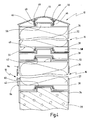
- Fig. 1 an inventive noise protection element is shown in its entirety and designated 10 in total.
- the noise protection element 10 has two posts 12, which in foundations 14 (not shown here, see. Fig. 10 ) can be embedded. It is understood that the post 12 can be anchored in a suitable substrate just as directly, for example by ramming.
- the posts 12 are presently designed as H-profiles.
- noise protection elements 10 according to the invention can be particularly easy to a Noise barrier be expanded.
- the wall part 16 is frontally closed by a grid assembly 18 to the outside. It is understood that the grid assembly 18 may be provided both front side and rearward on the wall part 16.
- the noise protection element 10 has a compensating element 20, which is used as a grounding and location of the wall part 16.
- the compensating element 20 may, for example, be cast together with the foundations 14 of the posts 12, possibly made of concrete or the like. In this case, it is conceivable on the one hand to produce the compensating element 20 directly on site, so that a height alignment can be carried out particularly easily taking into account the on-site conditions.
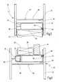
- the wall part 16 has at least one noise protection plate 22 (cf. Fig. 4 ), which are fixed by means of frame parts 24, which are arranged on end faces 26 of the noise protection plate 22, in receiving profiles 28 of the posts 12.
- the frame part 24 is fixed to the post 12 using an elastic clamping element 30.
- Fig. 2 shows an embodiment in which the determination is realized indirectly using a spacer 32.
- the noise protection element 10 can be constructed without special measures for adaptation of the frame parts 24 would be required on dimensions of the post 12.
- the frame parts 24 are preferably made of extruded profiles made of a metallic material, in particular of aluminum or an aluminum alloy, so that as few variants as possible are to be produced in order to promote the profitability of the method. Consequently, it is desirable to use only one profile size that is usable both on the right and left sides of the noise protection plate 22, and to allow adaptation to different sizes of posts 12, in this case the spacing of legs between which the frame parts 24 are received. This is done in a simple manner by spacers 32, which can be produced in a modular manner in different sizes with little effort, procured and kept.
- Fig. 4 shows a vertical section through an inventive noise protection element 10, wherein the representation of the posts 12 and the lateral frame parts 24 has been omitted for reasons of clarity.
- the noise protection element 10 has two wall parts 16 arranged one above the other, shown discontinuously.
- the lower wall part 16 is arranged on the compensation element 20.
- a ceiling profile 34 and a bottom profile 36 are provided on each wall part 16.
- the ceiling profile 34 and the bottom profile 36 may advantageously be formed as extruded components of an aluminum material. Alternatively, it is conceivable to produce these parts from sheets by bending or similar forming processes.
- inclined surfaces 40 and the bottom profile 36 inclined surfaces 42 are formed on the ceiling profile.
- a wall portion 16 which is usually supplied from above by insertion into the receiving profiles 28 of the posts 12, for example, by merely lowering to an already mounted wall portion 16 are aligned.
- the inclined surfaces 40, 42 have a shape that allows such a large mounting game that the to be mounted wall part 16 without additional guidance during installation always safe and accurate on an underlying ceiling profile 34 can come to rest. Accordingly, no special requirements are to be placed on the assembly of the noise protection element 10 according to the invention, provided that the compensation element 20 is aligned correctly. Nevertheless, a high accuracy can be achieved by the mating surfaces caused by the inclined surfaces 40, 42, which can be particularly easily secured by the above-described mounting of the elastic clamping elements 30.
- Fig. 4 is on the compensation element 20 as well as a ceiling profile 34 is provided.
- the embodied here by the ceiling profile 34 contour can also be realized directly in the compensation element 20. This is particularly useful when the compensating element 20 is made approximately by prototypes of concrete or the like.
- an intermediate profile 38 is arranged, which may also consist of an extruded aluminum material and therefore also readily with inclined surfaces 40, 42 may be provided to be mounted and aligned analogous to the wall portion 16.
- the intermediate profile 38 can serve the optical design subdivision of the noise protection element 10. Furthermore, with the intermediate profile 38, a height adjustment can be effected, for example, in a plurality of mutually adjacent arranged noise protection elements 10, which are placed along a slope, despite the changing height levels a uniform conclusion, namely for each of the noise protection elements 10, the same absolute height to realize ,
- intermediate profiles 38 can be arranged one above the other as needed.
- the noise protection element 10 is at the top by a final profile 44, also produced by extrusion or by sheet metal forming completed.
- the end profile 44 can serve aesthetic purposes and generally the protection of the noise protection element 10 against external influences.
- the end profile 44 for example, suitable for the discharge of precipitates, as well as to cover the elastic clamping elements 30 (in Fig. 4 not shown), which define the wall portion 16 located below the end profile 44 on the posts 12.
- the elastic clamping elements 30 can not be viewed from the outside or even undesirably manipulated or removed. In this way, an integrated closed, compact shape of the noise protection element 10 can result, so that the likelihood of wanton damage or destruction can be reduced.
- the end profile 44 is attached via a rear snap, a snap-in connection, on the underlying wall part 16.
- latching members 46 in the present case designed as curved springs, are provided.
- the locking members 46 are arranged in receptacles 48 of the end profile 44. It is also conceivable to carry out an end profile with integrated locking members in one piece. If this is done in an extruded profile, correspondingly lower elasticities and possible deformation paths of the latching members are to be considered.
- the end profile 44 is produced from a sheet metal, for example a sheet steel, by forming, sufficiently elastic locking members 46 can be formed on this sheet metal.
- the locking members 46 act in the assembled state with locking lugs 50 which are formed on the ceiling profile 34 of each wall portion 16, together.
- the inclined surface 40 which is also the recording and orientation of the soil profile Can serve 36, advantageously come as an assembly aid for use.
- the locking members 46 can slide, deflected or deformed during assembly of the end profile 44, and then, when the end profile 44 comes to rest against the underlying wall portion 16, snap behind the locking lugs 50.
- the ceiling profiles 34, the bottom profiles 36 and the intermediate profile 38 are designed such that upon contact with the edge surfaces 52, 54 of the noise protection plates 22 cavities 56, 58 result over the noise protection plates 22 effectively and can be vented. This can be effected particularly easily when using extruded ceiling profiles 34, floor profiles 36 and intermediate profiles 38 without additional manufacturing steps. It should be added that the noise protection plates 22 are formed as compact as possible, for example as a rectangular body, without exposed or filigree structures due to their limited inherent stability.
- noise protection plates 22 In plantable noise barriers a certain water absorption capacity of the noise protection plates 22 is quite desirable in order to provide moisture to adhering plants can. However, excessive water absorption and storage is to be avoided, since this is quite a Damage to the greening, such as through rot, may result. An excessively damp wall may result in a reduced soundproofing capability. In the noise protection element 10 according to the invention, an automatic ventilation and removal of excess water can be effected despite a high security against manipulation and a closed design.
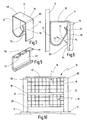
- the posts 12 may for example be designed as steel profiles, such as cold or hot rolled or drawn. Likewise, posts 12 made of extruded aluminum materials, concrete or masonry are conceivable. The posts 12 may also be formed of plastic.
- the posts 12 in the FIGS. 5 and 6 differ only in the width of the receiving profile 28. Usual widths may be about 160 mm, 180 mm or 200 mm. In contrast, the frame parts 24 in the FIGS. 5 and 6 identical outside dimensions.
- the frame parts 24 receptacles 62, in which a contact element 60 is arranged.
- the contact element 60 is advantageously designed as an elastomer, generally as a deformable body.
- the receptacles 62 are present undercut for receiving a Christmas tree profile.
- the contact element 60 can further improve the ability to compensate for tolerances in the assembly and operation of the noise protection element 10. Furthermore, a vibration decoupling of the wall parts 16 from the post 12 can thus be effected.
- the contact elements 60 can serve to avoid a direct mechanical contact between the posts 12 and the frame parts 24, so that damage, such as scratches, contact corrosion or the like, can be avoided during assembly and operation.
- the noise protection plate extends over the entire width of the frame part 24. It can be seen that a noise protection element 10 designed in this way can be planted from both sides.
- the frame part 24 in Fig. 6 Means are provided to accommodate in addition to the noise protection plate 22 and other plate or bar-shaped elements, preferably a photovoltaic device 64.
- a as shown in FIG Fig. 6 configured noise protection element 10 can thus be planted from one side, while the other side can be used to generate energy.
- FIGS. 5 and 6 clarify that in the attachment of the wall parts 16 to the post 12 no forces in the longitudinal direction of the wall parts 16 are effected, which could adversely affect the noise protection plates 22 or the photovoltaic device 64.
- the elastic clamping element 30 has a base leg 70 and a spreader leg 72.
- Such elastic clamping elements may be made of strip material, preferably spring steel strips, or of wire material.
- Fig. 7 shown embodiment of the elastic clamping member 30 is also suitable for urformenden production, such as plastic injection molding.
- a mounted elastic clamping element 30 is shown.
- the base leg 70 and the expansion leg 72 engage around the stop surface 25 of the frame part 24. Furthermore, the expansion limb 72 is supported rearwardly via a flat piece 71 on the post 12.
- the elastic clamping element 30 can be completed by simple bending process in the flow.
- the base leg 70, one or optionally a plurality of flat pieces 71 and the expansion limb 72 are interconnected via deflection regions 69, which represent transitions in the form of radii.
- the flat pieces 71 can also be replaced by bent portions, for example to effect increased deformability, but the flat pieces 71 are particularly suitable for mounting with a hammer, since they provide a suitable flat approach surface for the hammer blows.
- the expansion leg 72 also has an end portion 76, which in the present case based on the FIGS. 7 and 8 can be seen as a radius transition.
- the end region 76 can be made sharp-edged in the direction of the base limb 70 or the element to be clamped.
- the expansion limb 72 can be designed in its inclination relative to the base limb 70 such that release of the elastic clamping element 30 is only destructive.
- a curvature 75 on or formed, with which the clamping and holding action can be additionally reinforced or hedged.
- the elastic clamping element 30 can be secured non-positively and positively.
- Fig. 9 shows an example of a locking member 46, as it is for fastening the end profile 44 on the wall part 16 (see. Fig. 4 ) can be used.
- the locking member 46 may also be formed of a strip material, in particular a spring steel.
- receiving lugs 77, 78 are formed, which are inserted into the receptacle 48.
- the receiving lugs 77 are slightly entangled with respect to the receiving lug 78, so that good guidance and clamping of the latching member 46 in the receptacle 48 of the terminating profile 44 can result.
- the receptacle 48 of the end profile 44 can be manufactured with larger tolerances, thus with less effort.
- Fig. 10 finally shows a frontal view of the noise protection element 10 according to the invention. This may be the front or the back.
- the posts 12 are mounted on the foundations 14, for leveling the compensation element 20 is used.
- the two wall parts 16 are arranged, which are interrupted by the intermediate profile 38 and covered at the top by the end profile 44.
- the wall parts 16 have on the outside vertical bars 80 and horizontal bars 82, which are the grid assembly 18 associated. It can be seen that the vertical grid bars 80 have larger cross sections than the horizontal grid bars 82. With this configuration, the noise protection element 10 can be particularly well adapted to possible wind loads, the bidirectional structure of the grid assembly 18 leads to a configuration which simultaneously with high resistance material saving is formed.
- the grid arrangement 18 can be connected via flat profiles 84 to the ceiling profile 34 and the bottom profile 36 of the wall part 16.
- the vertical bars 80 can act as tie rods and on the one hand improve the cohesion of the wall portion 16, on the other hand dissipate it in the frame structure in the presence of external loads.
Landscapes
- Engineering & Computer Science (AREA)
- Architecture (AREA)
- Civil Engineering (AREA)
- Structural Engineering (AREA)
- Life Sciences & Earth Sciences (AREA)
- Sustainable Development (AREA)
- Building Environments (AREA)
Applications Claiming Priority (1)
| Application Number | Priority Date | Filing Date | Title |
|---|---|---|---|
| PCT/EP2010/000060 WO2011082717A1 (de) | 2010-01-08 | 2010-01-08 | Lärmschutzelement und lärmschutzwand |
Publications (2)
| Publication Number | Publication Date |
|---|---|
| EP2521815A1 EP2521815A1 (de) | 2012-11-14 |
| EP2521815B1 true EP2521815B1 (de) | 2016-10-26 |
Family
ID=42805950
Family Applications (1)
| Application Number | Title | Priority Date | Filing Date |
|---|---|---|---|
| EP10700941.7A Active EP2521815B1 (de) | 2010-01-08 | 2010-01-08 | Begrünbares lärmschutzelement und lärmschutzwand |
Country Status (4)
| Country | Link |
|---|---|
| EP (1) | EP2521815B1 (pl) |
| LT (1) | LT2521815T (pl) |
| PL (1) | PL2521815T3 (pl) |
| WO (1) | WO2011082717A1 (pl) |
Families Citing this family (1)
| Publication number | Priority date | Publication date | Assignee | Title |
|---|---|---|---|---|
| ITBO20120654A1 (it) * | 2012-11-30 | 2014-05-31 | Cir Ambiente S P A | Pannello, in particolare per barriere. |
Family Cites Families (6)
| Publication number | Priority date | Publication date | Assignee | Title |
|---|---|---|---|---|
| US4143495A (en) * | 1976-10-22 | 1979-03-13 | Fa. Pass & Co. | Sound-absorbing panel |
| NL8303128A (nl) * | 1983-09-09 | 1985-04-01 | Alcoa Nederland Bv | Geluidsisolerende wand. |
| US5467567A (en) * | 1992-12-29 | 1995-11-21 | The Reinforced Earth Company | Spring biased apparatus for maintaining precast panels in a stable removable position in a vertical slot |
| DE9311806U1 (de) * | 1993-08-07 | 1993-10-14 | Koch GmbH & Co. KG, 56412 Nentershausen | Lärmschutzelement zur Bildung von Lärmschutzwänden |
| DE29510861U1 (de) | 1995-07-05 | 1995-09-28 | Koch GmbH & Co. KG, 56412 Nentershausen | Lärmschutzwand |
| DE10310202A1 (de) | 2003-03-06 | 2004-09-16 | Maas-Gmbh | Lärmschutzwand |
-
2010
- 2010-01-08 EP EP10700941.7A patent/EP2521815B1/de active Active
- 2010-01-08 PL PL10700941T patent/PL2521815T3/pl unknown
- 2010-01-08 LT LTEP10700941.7T patent/LT2521815T/lt unknown
- 2010-01-08 WO PCT/EP2010/000060 patent/WO2011082717A1/de not_active Ceased
Also Published As
| Publication number | Publication date |
|---|---|
| LT2521815T (lt) | 2017-01-25 |
| WO2011082717A1 (de) | 2011-07-14 |
| EP2521815A1 (de) | 2012-11-14 |
| PL2521815T3 (pl) | 2017-04-28 |
Similar Documents
| Publication | Publication Date | Title |
|---|---|---|
| DE2842325A1 (de) | Absorbereinheit und daraus hergestelltes laermschutzschild | |
| EP2851477B1 (de) | Entwässerungsrinne | |
| DE2935745C2 (de) | Lärmschutzwand | |
| EP2278072A2 (de) | Schutzvorrichtung | |
| DE2013857A1 (de) | Befestigungsvorrichtung fur Wand Verkleidungsplatten | |
| EP2521815B1 (de) | Begrünbares lärmschutzelement und lärmschutzwand | |
| EP3473773B1 (de) | Wandelement zur verwendung bei einer einrichtung zum zurückhalten von wasser sowie einrichtung zum zurückhalten von wasser | |
| EP2447620A1 (de) | Vorrichtung zur Anordnung von Solarpaneelen und/oder Wärmekollektoren auf einem Untergrund sowie ein System, das wenigstens zwei solcher Vorrichtungen umfasst | |
| DE102005033545B4 (de) | Ausrüstungsträger mit zurgeordneter Beschwerungsmasse, der zur Befestigung bautechnischer Ausrüstungen dient | |
| EP3786362B1 (de) | Begrünbares wandelement, bausatz zur montage eines begrünbaren wandelements sowie verfahren zur montage eines begrünbaren wandelements | |
| EP2372267A2 (de) | Haltegestell für Solarmodule | |
| EP2006450B1 (de) | Schallabsorbierende Bauelemente einer Lärmschutzwand | |
| DE202005003255U1 (de) | Lärmschutzwand | |
| EP2522928A1 (de) | Vorrichtung für die Montage von Aufbauten auf einer flachen Ebene oder einer Ebene mit geringer Neigung | |
| DE102014217767A1 (de) | Schallschutzvorrichtung, insbesondere für eine Gleisanlage | |
| DE2451520C2 (de) | Lärmschutzelement | |
| EP3346058A1 (de) | Gabionenwandmodul und verfahren zur herstellung einer gabionenwand mit wenigstens einem gabionenwandmodul | |
| DE102010031294A1 (de) | Koppelelement eines Lärmschutzwandelementes mit dem Pfosten | |
| DE19710129A1 (de) | Künstliche Böschung | |
| DE9014624U1 (de) | Wand, insbesondere Sichtschutzwand, Lärmschutzwand, Stützwand oder Böschungswand | |
| EP1739250B1 (de) | Aufhängevorrichtung für eine Fassadenverkleidung mit Drahtgitterkörben | |
| EP1441067B1 (de) | Profilgitterelement | |
| DE29823733U1 (de) | Gitterkonstruktion zum Hinterfüllen mit Schüttmaterial | |
| DE19938676A1 (de) | Schallschutzwand für Verkehrswege | |
| DE102010031295A1 (de) | Koppelelement eines Lärmschutzwandelementes mit dem Pfosten |
Legal Events
| Date | Code | Title | Description |
|---|---|---|---|
| PUAI | Public reference made under article 153(3) epc to a published international application that has entered the european phase |
Free format text: ORIGINAL CODE: 0009012 |
|
| 17P | Request for examination filed |
Effective date: 20120808 |
|
| AK | Designated contracting states |
Kind code of ref document: A1 Designated state(s): AT BE BG CH CY CZ DE DK EE ES FI FR GB GR HR HU IE IS IT LI LT LU LV MC MK MT NL NO PL PT RO SE SI SK SM TR |
|
| DAX | Request for extension of the european patent (deleted) | ||
| 17Q | First examination report despatched |
Effective date: 20150625 |
|
| GRAP | Despatch of communication of intention to grant a patent |
Free format text: ORIGINAL CODE: EPIDOSNIGR1 |
|
| INTG | Intention to grant announced |
Effective date: 20160503 |
|
| GRAS | Grant fee paid |
Free format text: ORIGINAL CODE: EPIDOSNIGR3 |
|
| GRAA | (expected) grant |
Free format text: ORIGINAL CODE: 0009210 |
|
| AK | Designated contracting states |
Kind code of ref document: B1 Designated state(s): AT BE BG CH CY CZ DE DK EE ES FI FR GB GR HR HU IE IS IT LI LT LU LV MC MK MT NL NO PL PT RO SE SI SK SM TR |
|
| REG | Reference to a national code |
Ref country code: GB Ref legal event code: FG4D Free format text: NOT ENGLISH |
|
| REG | Reference to a national code |
Ref country code: CH Ref legal event code: EP |
|
| REG | Reference to a national code |
Ref country code: AT Ref legal event code: REF Ref document number: 840138 Country of ref document: AT Kind code of ref document: T Effective date: 20161115 Ref country code: CH Ref legal event code: NV Representative=s name: TROESCH SCHEIDEGGER WERNER AG, CH |
|
| REG | Reference to a national code |
Ref country code: IE Ref legal event code: FG4D Free format text: LANGUAGE OF EP DOCUMENT: GERMAN |
|
| REG | Reference to a national code |
Ref country code: DE Ref legal event code: R096 Ref document number: 502010012626 Country of ref document: DE |
|
| REG | Reference to a national code |
Ref country code: FR Ref legal event code: PLFP Year of fee payment: 8 |
|
| REG | Reference to a national code |
Ref country code: NL Ref legal event code: FP |
|
| REG | Reference to a national code |
Ref country code: EE Ref legal event code: FG4A Ref document number: E013241 Country of ref document: EE Effective date: 20170104 |
|
| PG25 | Lapsed in a contracting state [announced via postgrant information from national office to epo] |
Ref country code: NO Free format text: LAPSE BECAUSE OF FAILURE TO SUBMIT A TRANSLATION OF THE DESCRIPTION OR TO PAY THE FEE WITHIN THE PRESCRIBED TIME-LIMIT Effective date: 20170126 Ref country code: GR Free format text: LAPSE BECAUSE OF FAILURE TO SUBMIT A TRANSLATION OF THE DESCRIPTION OR TO PAY THE FEE WITHIN THE PRESCRIBED TIME-LIMIT Effective date: 20170127 Ref country code: SE Free format text: LAPSE BECAUSE OF FAILURE TO SUBMIT A TRANSLATION OF THE DESCRIPTION OR TO PAY THE FEE WITHIN THE PRESCRIBED TIME-LIMIT Effective date: 20161026 |
|
| PGFP | Annual fee paid to national office [announced via postgrant information from national office to epo] |
Ref country code: EE Payment date: 20170111 Year of fee payment: 8 Ref country code: LT Payment date: 20170106 Year of fee payment: 8 Ref country code: CH Payment date: 20170119 Year of fee payment: 8 |
|
| PG25 | Lapsed in a contracting state [announced via postgrant information from national office to epo] |
Ref country code: BE Free format text: LAPSE BECAUSE OF NON-PAYMENT OF DUE FEES Effective date: 20170131 Ref country code: FI Free format text: LAPSE BECAUSE OF FAILURE TO SUBMIT A TRANSLATION OF THE DESCRIPTION OR TO PAY THE FEE WITHIN THE PRESCRIBED TIME-LIMIT Effective date: 20161026 Ref country code: IS Free format text: LAPSE BECAUSE OF FAILURE TO SUBMIT A TRANSLATION OF THE DESCRIPTION OR TO PAY THE FEE WITHIN THE PRESCRIBED TIME-LIMIT Effective date: 20170226 Ref country code: HR Free format text: LAPSE BECAUSE OF FAILURE TO SUBMIT A TRANSLATION OF THE DESCRIPTION OR TO PAY THE FEE WITHIN THE PRESCRIBED TIME-LIMIT Effective date: 20161026 Ref country code: PT Free format text: LAPSE BECAUSE OF FAILURE TO SUBMIT A TRANSLATION OF THE DESCRIPTION OR TO PAY THE FEE WITHIN THE PRESCRIBED TIME-LIMIT Effective date: 20170227 Ref country code: ES Free format text: LAPSE BECAUSE OF FAILURE TO SUBMIT A TRANSLATION OF THE DESCRIPTION OR TO PAY THE FEE WITHIN THE PRESCRIBED TIME-LIMIT Effective date: 20161026 |
|
| PGFP | Annual fee paid to national office [announced via postgrant information from national office to epo] |
Ref country code: AT Payment date: 20170123 Year of fee payment: 8 Ref country code: CZ Payment date: 20170104 Year of fee payment: 8 |
|
| PGFP | Annual fee paid to national office [announced via postgrant information from national office to epo] |
Ref country code: TR Payment date: 20170111 Year of fee payment: 8 |
|
| REG | Reference to a national code |
Ref country code: DE Ref legal event code: R097 Ref document number: 502010012626 Country of ref document: DE |
|
| PG25 | Lapsed in a contracting state [announced via postgrant information from national office to epo] |
Ref country code: SK Free format text: LAPSE BECAUSE OF FAILURE TO SUBMIT A TRANSLATION OF THE DESCRIPTION OR TO PAY THE FEE WITHIN THE PRESCRIBED TIME-LIMIT Effective date: 20161026 Ref country code: RO Free format text: LAPSE BECAUSE OF FAILURE TO SUBMIT A TRANSLATION OF THE DESCRIPTION OR TO PAY THE FEE WITHIN THE PRESCRIBED TIME-LIMIT Effective date: 20161026 Ref country code: DK Free format text: LAPSE BECAUSE OF FAILURE TO SUBMIT A TRANSLATION OF THE DESCRIPTION OR TO PAY THE FEE WITHIN THE PRESCRIBED TIME-LIMIT Effective date: 20161026 |
|
| PG25 | Lapsed in a contracting state [announced via postgrant information from national office to epo] |
Ref country code: SM Free format text: LAPSE BECAUSE OF FAILURE TO SUBMIT A TRANSLATION OF THE DESCRIPTION OR TO PAY THE FEE WITHIN THE PRESCRIBED TIME-LIMIT Effective date: 20161026 Ref country code: IT Free format text: LAPSE BECAUSE OF FAILURE TO SUBMIT A TRANSLATION OF THE DESCRIPTION OR TO PAY THE FEE WITHIN THE PRESCRIBED TIME-LIMIT Effective date: 20161026 Ref country code: BG Free format text: LAPSE BECAUSE OF FAILURE TO SUBMIT A TRANSLATION OF THE DESCRIPTION OR TO PAY THE FEE WITHIN THE PRESCRIBED TIME-LIMIT Effective date: 20170126 |
|
| PLBE | No opposition filed within time limit |
Free format text: ORIGINAL CODE: 0009261 |
|
| STAA | Information on the status of an ep patent application or granted ep patent |
Free format text: STATUS: NO OPPOSITION FILED WITHIN TIME LIMIT |
|
| GBPC | Gb: european patent ceased through non-payment of renewal fee |
Effective date: 20170126 |
|
| PG25 | Lapsed in a contracting state [announced via postgrant information from national office to epo] |
Ref country code: MC Free format text: LAPSE BECAUSE OF FAILURE TO SUBMIT A TRANSLATION OF THE DESCRIPTION OR TO PAY THE FEE WITHIN THE PRESCRIBED TIME-LIMIT Effective date: 20161026 |
|
| 26N | No opposition filed |
Effective date: 20170727 |
|
| REG | Reference to a national code |
Ref country code: IE Ref legal event code: MM4A |
|
| PG25 | Lapsed in a contracting state [announced via postgrant information from national office to epo] |
Ref country code: GB Free format text: LAPSE BECAUSE OF NON-PAYMENT OF DUE FEES Effective date: 20170126 Ref country code: SI Free format text: LAPSE BECAUSE OF FAILURE TO SUBMIT A TRANSLATION OF THE DESCRIPTION OR TO PAY THE FEE WITHIN THE PRESCRIBED TIME-LIMIT Effective date: 20161026 Ref country code: LU Free format text: LAPSE BECAUSE OF NON-PAYMENT OF DUE FEES Effective date: 20170108 |
|
| REG | Reference to a national code |
Ref country code: FR Ref legal event code: PLFP Year of fee payment: 9 |
|
| REG | Reference to a national code |
Ref country code: BE Ref legal event code: MM Effective date: 20170131 |
|
| PG25 | Lapsed in a contracting state [announced via postgrant information from national office to epo] |
Ref country code: IE Free format text: LAPSE BECAUSE OF NON-PAYMENT OF DUE FEES Effective date: 20170108 |
|
| REG | Reference to a national code |
Ref country code: LT Ref legal event code: MM4D Effective date: 20180108 |
|
| REG | Reference to a national code |
Ref country code: EE Ref legal event code: MM4A Ref document number: E013241 Country of ref document: EE Effective date: 20180131 |
|
| REG | Reference to a national code |
Ref country code: CH Ref legal event code: PL |
|
| REG | Reference to a national code |
Ref country code: AT Ref legal event code: MM01 Ref document number: 840138 Country of ref document: AT Kind code of ref document: T Effective date: 20180108 |
|
| PG25 | Lapsed in a contracting state [announced via postgrant information from national office to epo] |
Ref country code: MT Free format text: LAPSE BECAUSE OF FAILURE TO SUBMIT A TRANSLATION OF THE DESCRIPTION OR TO PAY THE FEE WITHIN THE PRESCRIBED TIME-LIMIT Effective date: 20161026 |
|
| PG25 | Lapsed in a contracting state [announced via postgrant information from national office to epo] |
Ref country code: EE Free format text: LAPSE BECAUSE OF NON-PAYMENT OF DUE FEES Effective date: 20180131 Ref country code: LT Free format text: LAPSE BECAUSE OF NON-PAYMENT OF DUE FEES Effective date: 20180108 |
|
| PG25 | Lapsed in a contracting state [announced via postgrant information from national office to epo] |
Ref country code: CZ Free format text: LAPSE BECAUSE OF NON-PAYMENT OF DUE FEES Effective date: 20180108 Ref country code: CH Free format text: LAPSE BECAUSE OF NON-PAYMENT OF DUE FEES Effective date: 20180131 Ref country code: LI Free format text: LAPSE BECAUSE OF NON-PAYMENT OF DUE FEES Effective date: 20180131 Ref country code: AT Free format text: LAPSE BECAUSE OF NON-PAYMENT OF DUE FEES Effective date: 20180108 |
|
| PG25 | Lapsed in a contracting state [announced via postgrant information from national office to epo] |
Ref country code: HU Free format text: LAPSE BECAUSE OF FAILURE TO SUBMIT A TRANSLATION OF THE DESCRIPTION OR TO PAY THE FEE WITHIN THE PRESCRIBED TIME-LIMIT; INVALID AB INITIO Effective date: 20100108 |
|
| PG25 | Lapsed in a contracting state [announced via postgrant information from national office to epo] |
Ref country code: CY Free format text: LAPSE BECAUSE OF NON-PAYMENT OF DUE FEES Effective date: 20161026 |
|
| PG25 | Lapsed in a contracting state [announced via postgrant information from national office to epo] |
Ref country code: MK Free format text: LAPSE BECAUSE OF FAILURE TO SUBMIT A TRANSLATION OF THE DESCRIPTION OR TO PAY THE FEE WITHIN THE PRESCRIBED TIME-LIMIT Effective date: 20161026 |
|
| PG25 | Lapsed in a contracting state [announced via postgrant information from national office to epo] |
Ref country code: TR Free format text: LAPSE BECAUSE OF NON-PAYMENT OF DUE FEES Effective date: 20180108 |
|
| PGFP | Annual fee paid to national office [announced via postgrant information from national office to epo] |
Ref country code: LV Payment date: 20230115 Year of fee payment: 14 |
|
| P01 | Opt-out of the competence of the unified patent court (upc) registered |
Effective date: 20230513 |
|
| PG25 | Lapsed in a contracting state [announced via postgrant information from national office to epo] |
Ref country code: LV Free format text: LAPSE BECAUSE OF NON-PAYMENT OF DUE FEES Effective date: 20240108 |
|
| PG25 | Lapsed in a contracting state [announced via postgrant information from national office to epo] |
Ref country code: LV Free format text: LAPSE BECAUSE OF NON-PAYMENT OF DUE FEES Effective date: 20240108 |
|
| PGFP | Annual fee paid to national office [announced via postgrant information from national office to epo] |
Ref country code: DE Payment date: 20250226 Year of fee payment: 16 |
|
| PGFP | Annual fee paid to national office [announced via postgrant information from national office to epo] |
Ref country code: FR Payment date: 20250127 Year of fee payment: 16 |
|
| PGFP | Annual fee paid to national office [announced via postgrant information from national office to epo] |
Ref country code: PL Payment date: 20251229 Year of fee payment: 17 |
|
| PGFP | Annual fee paid to national office [announced via postgrant information from national office to epo] |
Ref country code: NL Payment date: 20260121 Year of fee payment: 17 |