EP2520398A1 - Drive device and conveyance device - Google Patents
Drive device and conveyance device Download PDFInfo
- Publication number
- EP2520398A1 EP2520398A1 EP10840757A EP10840757A EP2520398A1 EP 2520398 A1 EP2520398 A1 EP 2520398A1 EP 10840757 A EP10840757 A EP 10840757A EP 10840757 A EP10840757 A EP 10840757A EP 2520398 A1 EP2520398 A1 EP 2520398A1
- Authority
- EP
- European Patent Office
- Prior art keywords
- arm
- actuator
- arm unit
- conveyance
- drive device
- Prior art date
- Legal status (The legal status is an assumption and is not a legal conclusion. Google has not performed a legal analysis and makes no representation as to the accuracy of the status listed.)
- Withdrawn
Links
Images








Classifications
-
- B—PERFORMING OPERATIONS; TRANSPORTING
- B25—HAND TOOLS; PORTABLE POWER-DRIVEN TOOLS; MANIPULATORS
- B25J—MANIPULATORS; CHAMBERS PROVIDED WITH MANIPULATION DEVICES
- B25J9/00—Program-controlled manipulators
- B25J9/06—Program-controlled manipulators characterised by multi-articulated arms
-
- H—ELECTRICITY
- H10—SEMICONDUCTOR DEVICES; ELECTRIC SOLID-STATE DEVICES NOT OTHERWISE PROVIDED FOR
- H10P—GENERIC PROCESSES OR APPARATUS FOR THE MANUFACTURE OR TREATMENT OF DEVICES COVERED BY CLASS H10
- H10P72/00—Handling or holding of wafers, substrates or devices during manufacture or treatment thereof
- H10P72/30—Handling or holding of wafers, substrates or devices during manufacture or treatment thereof for conveying, e.g. between different workstations
- H10P72/33—Handling or holding of wafers, substrates or devices during manufacture or treatment thereof for conveying, e.g. between different workstations into and out of processing chamber
- H10P72/3302—Mechanical parts of transfer devices
-
- B—PERFORMING OPERATIONS; TRANSPORTING
- B25—HAND TOOLS; PORTABLE POWER-DRIVEN TOOLS; MANIPULATORS
- B25J—MANIPULATORS; CHAMBERS PROVIDED WITH MANIPULATION DEVICES
- B25J11/00—Manipulators not otherwise provided for
- B25J11/0095—Manipulators transporting wafers
-
- B—PERFORMING OPERATIONS; TRANSPORTING
- B25—HAND TOOLS; PORTABLE POWER-DRIVEN TOOLS; MANIPULATORS
- B25J—MANIPULATORS; CHAMBERS PROVIDED WITH MANIPULATION DEVICES
- B25J9/00—Program-controlled manipulators
- B25J9/02—Program-controlled manipulators characterised by movement of the arms, e.g. cartesian coordinate type
- B25J9/04—Program-controlled manipulators characterised by movement of the arms, e.g. cartesian coordinate type by rotating at least one arm, excluding the head movement itself, e.g. cylindrical coordinate type or polar coordinate type
- B25J9/041—Cylindrical coordinate type
- B25J9/042—Cylindrical coordinate type comprising an articulated arm
- B25J9/043—Cylindrical coordinate type comprising an articulated arm double selective compliance articulated robot arms [SCARA]
-
- B—PERFORMING OPERATIONS; TRANSPORTING
- B25—HAND TOOLS; PORTABLE POWER-DRIVEN TOOLS; MANIPULATORS
- B25J—MANIPULATORS; CHAMBERS PROVIDED WITH MANIPULATION DEVICES
- B25J9/00—Program-controlled manipulators
- B25J9/10—Program-controlled manipulators characterised by positioning means for manipulator elements
- B25J9/106—Program-controlled manipulators characterised by positioning means for manipulator elements with articulated links
- B25J9/1065—Program-controlled manipulators characterised by positioning means for manipulator elements with articulated links with parallelograms
-
- B—PERFORMING OPERATIONS; TRANSPORTING
- B25—HAND TOOLS; PORTABLE POWER-DRIVEN TOOLS; MANIPULATORS
- B25J—MANIPULATORS; CHAMBERS PROVIDED WITH MANIPULATION DEVICES
- B25J9/00—Program-controlled manipulators
- B25J9/10—Program-controlled manipulators characterised by positioning means for manipulator elements
- B25J9/12—Program-controlled manipulators characterised by positioning means for manipulator elements electric
- B25J9/126—Rotary actuators
-
- B—PERFORMING OPERATIONS; TRANSPORTING
- B25—HAND TOOLS; PORTABLE POWER-DRIVEN TOOLS; MANIPULATORS
- B25J—MANIPULATORS; CHAMBERS PROVIDED WITH MANIPULATION DEVICES
- B25J9/00—Program-controlled manipulators
- B25J9/003—Program-controlled manipulators having parallel kinematics
Definitions
- the present invention relates to a conveyance device that conveys a semi-conductor substrate, a glass substrate, and the like, and to a drive device to be used in the same.
- conveyance devices each including multijoint arms as a conveyance means for conveying a conveyance object such as a wafer or glass substrate under vacuum or in a process gas atmosphere, for example. Extending and retracting or turning the arm, such a conveyance device moves a distal end of the arm to an arbitrary position and conveys the conveyance object.
- Some arms allow three-dimensional movement by extending and retracting or turning in a horizontal direction with a rotational power in the horizontal direction and moving up and down in a vertical direction.
- a drive portion that drives the arm needs a mechanism for generating the rotational power in the horizontal direction and a mechanism for moving up and down in the vertical direction.
- Patent Document 1 describes a conveyance device including a casing that houses main parts of a drive portion and a drive-portion support frame housed in the casing.
- the drive-portion support frame supports a plurality of motors and the like for extending/retracting and turning arms and the like.
- the drive-portion support frame moves up and down within the casing along linear guide rails provided in the vertical direction via a ball screw mechanism by the motors provided at the bottom portion of the casing.
- all the arms move up and down (for example, see paragraph [0016] and FIG. 1 of Patent Document 1).
- a base plate is connected to the upper portion of the casing.
- the base plate is provided in an opening portion formed in a scaffold (fixing portion) in the vacuum atmosphere. That is, the drive portion is supported by the base plate such that (the drive portion of) the conveyance device is hung from the opening portion formed in the scaffold.
- Patent Document1 Japanese Patent Application Laid-open No. 2008-135630
- a drive device that drives a conveyance body and includes an actuator and a frame, the conveyance body being provided within a chamber including a division wall and capable of conveying a conveyance object.
- the actuator drives the conveyance body.
- the frame is formed by integral molding, is connected to the division wall of the chamber, and installs the actuator.
- a conveyance device includes a conveyance body, an actuator, and a frame.
- the conveyance body is provided in a chamber including a division wall and is capable of conveying a conveyance object.
- the actuator drives the conveyance body.
- the frame is formed by integral molding, is connected to the division wall of the chamber, and installs the actuator.
- a drive device is a drive device that drives a conveyance body and includes an actuator and a frame, the conveyance body being provided within a chamber including a division wall and capable of conveying a conveyance object.
- the actuator drives the conveyance body.
- the frame is formed by integral molding, is connected to the division wall of the chamber, and installs the actuator.
- the frame is formed by integral molding, and hence it is possible to enhance the rigidity and durability of the frame.
- a part of the frame is connected to the division wall, and hence even if a stress due to a reaction when the actuator drives the conveyance body is added to the frame, it is possible to reliably prevent damages and the like of the frame.
- the actuator may include a turn shaft, a motor, and a support base.
- the turn shaft is connected to the conveyance body and turns the conveyance body.
- the motor provides the turn shaft with a rotational driving force.
- the support base supports the turn shaft and the motor.
- the actuator the turning shaft and the motor are integrated by the support base.
- the drive device includes the actuator and the frame.
- the conveyance body may be a multijoint-type arm unit.
- the actuator further includes an extension and retraction shaft for extending and retracting an arm of the arm unit.
- the frame may include a connecting portion, an opposed portion, and a coupling portion.
- the connecting portion is connected to the division wall.
- the opposed portion is provided to be opposed to the connecting portion.
- the coupling portion couples the connecting portion and the opposed portion to each other such that the support base is provided between the connecting portion and the opposed portion.
- the user is able to assemble the thus integrated actuator to the frame in such a manner that the actuator is inserted from a side of the connecting portion or a side of the opposed portion into the frame.
- the actuator may further include a raising and lowering mechanism that raises and lowers the support base between the connecting portion and the opposed portion.
- a raising and lowering mechanism that raises and lowers the support base between the connecting portion and the opposed portion.
- the connecting portion or the opposed portion may include a cutout portion
- the raising and lowering mechanism may include a raising and lowering drive source unit provided to the cutout portion.
- the conveyance body may be a multijoint-type arm unit and include a plurality of conveyance bodies.
- the actuator only needs to include a first rotating shaft, a second rotating shaft, a turning shaft, and a motor.
- the first rotating shaft is connected to a first arm unit of the plurality of arm units and extends and retracts an arm of the first arm unit.
- the second rotating shaft is connected to a second arm unit of the plurality of arm units and extends and retracts an arm of the second arm unit.
- the turning shaft integrally turns the first arm unit and the second arm unit.
- the motors each drive the first rotating shaft, the second rotating shaft, and the turning shaft.
- the motors may be arranged at equiangular intervals along a direction in which the first arm unit and the second arm unit turn. Thus, it is possible to evenly distribute a stress added to the frame and the like via the motors.
- the actuator may further include a raising and lowering motor and a plurality of guide shafts.
- the raising and lowering motor raises and lowers the support base along a direction in which the shaft extends.
- the plurality of guide shafts are arranged at equiangular intervals along a direction in which the shaft rotates to guide raising and lowering operations of the support base by the raising and lowering motor.
- the coupling portion may include a plurality of coupling portions arranged at equiangular intervals in a circumference with the turn shaft being a center.
- the conveyance body may be a single multijoint-type arm unit.
- the actuator includes a rotating shaft, a turning shaft, and motors.
- the rotating shaft is connected to the arm unit and extends and retracts an arm of the arm unit.
- the turning shaft turns the arm unit.
- the motors each drive the rotating shaft and the turning shaft.
- a conveyance device includes a conveyance body, an actuator, and a frame.
- the conveyance body is provided in a chamber including a division wall and is capable of conveying a conveyance object.
- the actuator drives the conveyance body.
- the frame is formed by integral molding, is connected to the division wall of the chamber, and installs the actuator.
- FIG. 1 is a perspective view showing a conveyance device according to an embodiment of the present invention.
- a conveyance device 100 conveys a substrate G being a conveyance object between chambers for processing under vacuum, for example.
- the examples of the substrate G include a glass substrate provided to a display device.
- the conveyance device 100 includes two arm units 30 and a drive unit 50 (drive device).
- the arm units 30 are provided to the upper portion of the conveyance device 100 and each serve as a conveyance body.
- the drive unit 50 is connected to the arm units 30 beneath the arm units 30 and drives the arm units 30.
- Each of the two arm units 30 includes a first arm 1, a second arm 2, a third arm 3, a fourth arm 4, a link member 5, a hand base 6, and a hand member 7. Further, the two arm units 30 include a common turning block 8. The two arm units 30 are capable of extending and retracting independently of each other. Further, the turning block 8 is turned by a single turning shaft 73 driven by the drive unit 50, which will be described later. When the turning block 8 turns, the two arm units 30 integrally turn. The two arm units 30 have substantially the same structure. Hereinafter, therefore, the structure of one of the arm units 30 will be described.
- the first arm 1 and the second arm 2 constitute a parallel link and the third arm 3 and the fourth arm 4 constitute another parallel link.
- a first joint shaft 11 is connected to the drive unit 50 via the turning block 8.
- the first joint shafts 11 are connected via the turning block 8 to a single common shaft 71 (or 72)(see FIG. 8 ) provided to the drive unit 50.
- the single shaft 71 (or 72) is driven to rotate in the drive unit 50, one of the arm units 30 extends or retracts.
- each of the first arm 1 and the second arm 2 is provided with a second joint shaft 12.
- One end of each of the third arm 3 and the fourth arm 4 is provided with a guide shaft 15.
- the guide shaft 15 is connected to a guide plate 16 as will be described later.
- the hand base 6 is connected via the third joint shaft 13, the hand base 6 having a T-like plate shape.
- the hand base 6 is provided with the hand member 7 including two long members, for example. Thereby, the substrate G is disposed on the hand member 7.
- the hand member 7 is provided with a mechanism (not shown) for supporting the substrate G using vacuum adsorption, for example.
- the second joint shafts 12 described above are connected.
- the first arm 1 and the second arm 2 are connected to the third arm 3 and the fourth arm 4, respectively.
- the link member 5 is connected to the first arm 1 and the second arm 2 via link shafts 14.
- the link member 5 assists the function of the parallel link of the first arm 1 and the second arm 2.
- bearing rollers 18 are connected to end portions of the guide shafts 15, which is on an opposite side of a side on which the third arm 3 and the fourth arm 4 are connected thereto.
- Each of the bearing rollers 18 is engaged to a cam groove 17a formed to have a long-hole shape in a cam plate 17 attached to the guide plate 16.
- the guide plate 16 is connected to the first arm 1 and the second arm 2 via the link shafts 14 described above.
- the bearing roller 18 is, within each cam groove 17a, positioned at an end portion of the cam groove 17a on a side away from center shafts (three coaxial shafts 75) of the drive unit 50.
- the bearing roller 18 is, within each cam groove 17a, positioned at an end portion of the cam groove 17a on a side closer to the three coaxial shafts 75 of the drive unit 50.
- both the arm units 30 are capable of extending and retracting without interferences.
- Each of the one ends of the third arm 3 and the fourth arm 4 is free to move in one direction and guided in the one direction by the guide shaft 15 and the cam plate.
- the one direction means a direction orthogonal to a direction in which the arm unit 30 extends and retracts.
- a guide mechanism 10 acts to limit the movement of an end portion of a second parallel link mechanism 32 in a Y-axis direction.
- a retaining portion 67 which is the acting end of the second parallel link mechanism 32, and its positioning with high accurate.
- the guide mechanism 10 it is possible to achieve downsizing of the arm unit 30. At the same time, even when the substrate G having a large size is conveyed, it is possible to ensure an operating range of the arm unit 30 corresponding to a desired occupied footprint of the large substrate G.
- FIG. 2 is a plan view showing a cluster type vacuum processing apparatus to which the conveyance device 100 according to this embodiment is applied, for example.
- This vacuum processing apparatus 200 includes a plurality of vacuum processing units 210, a load-lock unit 220, and a conveyance unit 150.
- the conveyance unit 150 is connected to the vacuum processing units 210 and the load-lock unit 220 via respective gates 205.
- the vacuum processing units 210 are units for performing, for example, PVD (Physical Vapor Deposition), CVD (Chemical Vapor Deposition), or other vacuum processing.
- the conveyance unit 150 includes a conveyance chamber 151 capable of maintaining a vacuum state, for example.
- the arm units 30 of the conveyance device 100 are provided within the conveyance chamber 151.
- the drive unit 50 of the conveyance device 100 is provided outside the conveyance chamber 151.
- the conveyance device 100 is capable of accessing the load-lock unit 220 and the vacuum processing units 210 and conveying the substrate G thereto/therefrom.
- the apparatus to which the conveyance device 100 is applied is not limited to the cluster type one described above and the conveyance device 100 is applicable to various vacuum processing apparatuses 200.
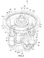
- FIG. 3 is a perspective view showing the drive unit 50 and FIG. 4 is a plan view thereof.
- the drive unit 50 includes a actuator 70 and a frame 60 installing the actuator 70.
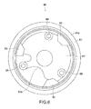
- FIG. 5 is a perspective view showing the frame 60 and FIG. 6 is a plan view thereof.
- the frame 60 is made of metal material such as iron and steel, aluminum, or magnesium and formed by integral molding by casting.
- the frame 60 includes a connecting portion 61, a bottom plate portion 62, and a plurality of coupling portions 63.
- the connecting portion 61 is connectable to a division wall 152 (see FIG. 8 ) of the conveyance chamber 151 described above.
- the bottom plate portion 62 is provided to be opposed to the connecting portion 61 and serves as an opposed portion.
- the plurality of coupling portions 63 couple the connecting portion 61 and the bottom plate portion 62 to each other.
- the connecting portion 61 is formed in a ring shape and includes a flange 61a. It should be noted that a lid 65 can be attached and detached to/from the connecting portion 61. Although not shown in the figures, the flange 61a is provided with a plurality of holes through which bolts pass. By fixing the flange 61a to an opening portion 152a formed in the division wall 152 with bolts 53 as shown in FIG. 8 , the frame 60 is fixed to the division wall 152.
- the three coupling portions 63 are provided.
- the coupling portions 63 are arranged at equiangular intervals, i.e., 120° intervals along a turning direction of the arm unit 30 (in circumference with shafts 75 being center). Further, each of the coupling portions 63 on a side closer to the connecting portion 61 than the bottom plate portion 62 is formed to be wider than on a side of the bottom plate portion 62.
- the frame 60 is formed by the integral molding, and hence it is possible to enhance the rigidity and durability of the frame 60. In particular, it is possible to realize the frame 60 having sufficient resistance to a stress due to a reaction of the actuator 70 during driving of the arm unit 30.
- the frame 60 is formed by the integral molding, and hence the number of components can be reduced. Therefore, assembling of the drive unit 50 becomes easy.
- the coupling portions 63 are arranged at the equiangular intervals along the turning direction of the arm unit 30, and hence it is possible to evenly distribute a stress added to the coupling portions 63 and the connecting portion 61 especially when the arm unit 30 turns.
- the portions of the coupling portions 63 on the side of the connecting portion 61 become portions subjected to a large shear stress of the stress due to the reaction during the driving of the arm unit 30.
- Each of the coupling portions 63 on the connecting portion 61 side is formed to be wider than on the bottom plate portion 62 side, and hence it is possible to realize the frame 60 rigid enough to endure the stress described above.
- FIG. 7 is a perspective view showing the actuator 70.
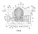
- FIG. 8 is a schematic cross-sectional view taken along the line A-A of FIG. 4 .
- FIG. 8 shows a state in which the actuator 70 is installed in the frame 60.
- the actuator 70 includes the three coaxial shafts 75 (two rotating shafts 71 and 72 and single turning shaft 73), three motors 74, and a transmission mechanism.
- the transmission mechanism transmits a rotational driving force generated by the three motors 74 to the three shafts 75.
- the turning shaft 73 and the rotating shaft 72 are each formed to have a hollow shape.
- the rotating shaft 72 having a smaller diameter than that of the turning shaft 73 is provided.
- the rotating shaft 71 having a smaller than that of the rotating shaft 72 is, in turn, provided.
- the transmission mechanism typically includes driving pulleys 76, driven pulleys 83, and belts 77.
- Each of the driving pulleys 76 is connected to each of the motors 74.
- Each of the driven pulleys 83 is provided to each of the shafts 71, 72, and 73.
- Each of the belts 77 is bridged between the driving pulley 76 and the driven pulley 83.
- the actuator 70 includes a support base 40 that supports the three shafts 75, the motors 74, and the like.
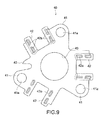
- FIG. 9 is a plan view showing the support base 40.
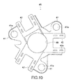
- FIG. 10 is a bottom view showing the support base 40.
- the support base 40 is formed by integral molding by casting.
- the support base 40 includes motor-mounting portions 42 arranged around the opening 49 at equiangular intervals along a rotation direction of the three shafts 75 (the turning direction of the arm unit 30).
- the motor-mounting portions 42 are provided to be different in height from each other depending on the height positions of the driven pulleys 83 of the shafts 71, 72, and 73. Therefore, the motors 74 are provided in different heights.
- the motor-mounting portions 42 are provided with screw holes 42a. The motors 74 are fixed on the support base 40 with screws.
- vacuum-sealed bearings 82 Between the rotating shaft 71 and the rotating shaft 72 and between the rotating shaft 72 and the turning shaft 73, there are provided vacuum-sealed bearings 82. Also, between the turning shaft 73 and an outer tube 81 uprightly provided on the support base 40, vacuum-sealed bearings 82 are further provided. On an outer peripheral side of the outer tube 81, between the support base 40 and a backside of the connecting portion 61 of the frame 60, a bellows 79 is provided. With this configuration, it becomes possible to maintain the outside of the bellows 79 at atmospheric pressure and the inside of the division wall 152 of the conveyance chamber 151 in a vacuum state.
- the actuator 70 includes a raising and lowering mechanism 35 (not shown in FIG. 7 ) that drives the support base 40 to move up and down.
- the raising and lowering mechanism 35 includes a raising and lowering drive source unit 36 and a ball screw 37.
- the raising and lowering drive source unit 36 is mounted to the bottom plate portion 62.
- the ball screw 37 is provided to extend from the raising and lowering drive source unit 36 and driven to rotate by the raising and lowering drive source unit 36.
- a drive mechanism for driving the ball screw 37 of the raising and lowering drive source unit 36 is, although not shown in the figures, constituted of a raising and lowering motor, a belt, pulleys (partially shown in the figures), and the like.
- the raising and lowering drive source unit 36 is fixed with a bolt or the like in a cutout portion 62a (see FIG. 5 ) formed in the bottom plate portion 62.
- the support base 40 is provided with an insertion portion 43 into which the ball screw 37 is inserted.
- a ball nut 78 is fastened in a lower portion of the insertion portion 43.
- the support base 40 includes a plurality of guide portions 41 arranged at equiangular intervals along the rotation direction of the shafts 71, 72, and 73.
- Each of the guide portions 41 includes a hole 41a, into which a raising and lowering guide shaft 64 (see FIGS. 3 and 8 and the like) is inserted, and a bearing (bush) that supports the raising and lowering guide shaft 64. Smooth raising and lowering operations by the raising and lowering guide shafts 64 are thus ensured.
- the raising and lowering guide shafts 64 are mounted and fixed to mounting portions 69.
- Each of the mounting portions 69 is provided to the bottom plate portion 62 of the frame 60 shown in FIG. 5 and has a hole shape.
- the three raising and lowering guide shafts 64 are provided and arranged at 120° intervals along the rotation direction of the shafts 71, 72, and 73.
- the ball screw 37 of the raising and lowering mechanism 35 rotates, the ball nut 78 receives the rotational power.
- the support base 40 moves up and down while being guided by the raising and lowering guide shafts 64 in the guide portions 41.
- the turning block 8 and both the arm units 30 move up and down.
- the shafts and the motors 74 are integrated by the support base 40.
- the shafts and the motors 74 are integrated by the support base 40.
- the motors 74 are arranged at equiangular intervals, and hence it is possible to evenly distribute a stress added to the frame 60 via the motors 74 during turning of the arm units 30.
- the raising and lowering guide shafts 64 are also arranged at equiangular intervals, and hence it is possible to evenly distribute a stress added to the guide shafts 64 and a stress added to the frame 60 via the guide shafts 64.
- FIG. 11 is a schematic cross-sectional view showing an inner structure of the turning block 8.
- FIG. 12 is a plan view showing engagement states of gears within the turning block 8.
- the turning block 8 includes a case 27 fixed to the turning shaft 73. Within the case 27, a gear 21 is fixed to the rotating shaft 71 and a gear 22 is fixed to the rotating shaft 72. At the center of the gear 22, there is formed a hole through which the rotating shaft 71 passes. The gears 21 and 22 are coaxially arranged.
- gears 25a and 25b that mesh with the gear 21 are fixed, respectively.
- the gears 25a and 25b are arranged side by side in a horizontal plane.
- gears 26a and 26b that mesh the gear 22 are fixed, respectively.
- the gears 26a and 26b are arranged side by side in a horizontal plane.
- each of the first joint shafts 11 is housed in a tubular case 24 via a bearing 23.
- the cases 24 are fixed to the case 27 of the turning block 8.
- the drive unit 50 can be driven to extend and retract using the coaxial rotating shafts 71 and 72 with the arm units 30 being independent of each other, and can turn both the arm units 30 using the turning shaft 73 coaxial with the rotating shafts 71 and 72.
- the driving shafts 11 rotate relative to the respective cases 37 due to an inertial force, and hence the rotating shafts 71 and 72 may be driven so as to suppress such rotation.
- the rotating shafts 71 and 72 may be driven in synchronization with the driving of the turning shaft 73 to rotate.
- FIG. 13 is a perspective view schematically showing a conveyance device according to a second embodiment of the present invention.
- a conveyance device 200 according to this embodiment includes an arm unit 210 and a drive unit 220 (drive device).
- the arm unit 210 serves as the conveyance body.
- the drive unit 220 drives the arm unit 210 to turn, extend/retract, and move up/down.
- the arm unit 210 includes a multijoint arm 201, a hand member 202 formed at a distal end of the multijoint arm 201, and a turning block 203 that supports the multijoint arm 201.
- the multijoint arm 201 is constituted of a coupling body of a first arm 201a and a second arm 201b. One end of the first arm 201a is connected to the turning block 203. The other end of the first arm 201a is rotatably connected to one end of the second arm 202 via a rotational shaft R2. The other end of the second arm 201b is rotatably connected to the hand member 202 via a rotational shaft R3.
- the arm unit 210 thus configured constitutes a so-called SCARA (Selective Compliance Assembly Robot Arm) type substrate-conveying robot.
- the drive unit 220 includes a turning shaft 273 and a rotating shaft 271.
- the turning shaft 273 is connected to the turning block 203 and turns the arm unit 210 in a horizontal plane in cooperation with the turning block 203.
- the rotating shaft 271 is connected to a rotational shaft R1, the rotational shaft R1 being mounted to the end of the first arm 201a so as to penetrate the turning block 203.
- the rotational shaft R1 and the rotational shaft R2 are coupled to each other via a first timing belt (omitted in the figures).
- the rotational shaft R2 and the rotational shaft R3 are coupled to each other via a second timing belt (omitted in the figures).
- the multijoint arm 201 is driven to extend and retract.
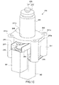
- FIG. 14 is a perspective view of the drive unit 220.
- the drive unit 220 includes an actuator 270 and a frame 260 installing the actuator 270.
- FIG. 15 is a perspective view of the actuator 270 and
- FIG. 16 is a cross-sectional view of main parts of the actuator 270.
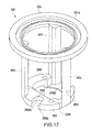
- FIG. 17 is a perspective view of the frame 260.
- the frame 260 is made of metal material such as iron and steel, aluminum, or magnesium and formed by integral molding by casting.
- the frame 260 includes a connecting portion 261, a bottom plate portion 262, and a plurality of coupling portions 263.
- the connecting portion 261 is connectable to a division wall of a conveyance chamber (see FIG. 8 ).
- the bottom plate portion 262 is provided to be opposed to the connecting portion 261 and serves as the opposed portion.
- the plurality of coupling portions 263 couple the connecting portion 261 and the bottom plate portion 262 to each other.
- the connecting portion 261 is formed in a ring shape and includes a flange 261a. It should be noted that a lid 265 can be attached and detached to/from the connecting portion 261.
- the flange 261a is provided with a plurality of holes through which bolts pass.
- the frame 260 is fixed to the division wall.
- the three coupling portions 263 are provided. The coupling portions 263 are arranged at equiangular intervals, i.e., 120° intervals along a turning direction of the arm unit 210.
- the frame 260 is formed by the integral molding, and hence it is possible to enhance the rigidity and durability of the frame 260. In particular, it is possible to realize the frame 260 having sufficient resistance to a stress due to a reaction of the actuator 270 during driving of the arm unit 210.
- the frame 260 is formed by the integral molding, and hence the number of components can be reduced. Therefore, assembling of the drive unit 220 becomes easy.
- the coupling portions 263 are arranged at the equiangular intervals along the turning direction of the arm unit 210, and hence it is possible to evenly distribute a stress added to the coupling portions 263 and the connecting portion 261 especially when the arm unit 210 turns.
- the actuator 270 includes two coaxial shafts (single rotating shaft 271 and single turning shaft 273) and two motors M1 and M2.
- the motor M1 is connected to a lower end of the rotating shaft 271 and rotates the rotating shaft 271.
- the motor M1 passes through an opening 262a ( FIG. 17 ) formed at the center of the bottom plate portion 262 of the frame 260.
- the motor M2 rotates the turning shaft 273 via a rotation transmission mechanism.
- the bottom plate portion 262 is provided with a thin-wall portion 262b ( FIG. 17 ).
- the turning shaft 273 is formed to have a hollow shape. Into the turning shaft 273, the rotating shaft 271 is provided having a smaller diameter than that of the turning shaft 273. As shown in FIGS. 15 and 16 , the transmission mechanism typically includes a driving pulley 276, a driven pulley 283, and a belt 277.
- the driving pulley 276 is connected to the motor M1.
- the driven pulley 283 is provided to the turning shaft 273.
- the belt 277 is bridged between the driving pulley 276 and the driven pulley 283.
- the actuator 270 includes a support base 240 that supports the two shafts 275, the motors M1 and M2, and the like.
- the support base 240 is made of, for example, the metal material same as the frame 260 and formed by integral molding by casting.
- the transmission mechanism includes an adjustment unit 290 for adjusting the tension of the belt 277.
- the adjustment unit 290 includes a movable body 291, a fixing plate 292, and an adjustment portion 293.
- the movable body 291 supports the motor M2.
- the fixing plate 292 is fixed on the support base 240 and supports the movable body 291.
- the adjustment portion 293 is capable of moving the movable body 291 with respect to the fixing plate 292.
- the adjustment unit 290 includes a bracket 293a and a bolt member 293b.
- the bracket 293a is fixed on the support base 240.
- the bolt member 293b has a distal end to be screwed into the bracket 293a and abut against the movable body 291.
- the driving shaft of the motor M1 passes through a long hole 291a and is coupled to the rotating shaft 271, the long hole 291a being formed in a bottom surface of the movable body 291. Between the movable body 291 and the fixing plate 292, there is provided a linear guide rail 294.
- the adjustment unit 290 moves the movable body 291 relative to the fixing plate 292 in directions in which the driving pulley 276 and the driven pulley 283 move away from/closer to each other by a rotation operation of the bolt member 293b.
- the actuator 270 it is possible to prevent the actuator 270 from increasing in size and realize the adjustment mechanism using the belt tension.
- the actuator 270 includes a raising and lowering mechanism 236 that drives the support base 240 to move up and down with respect to the frame 260.
- the raising and lowering mechanism 236 includes a motor M3 and a ball screw 237.
- the motor M3 is mounted to the bottom plate portion 262.
- the ball screw 237 is driven to rotate by the motor M3.
- An upper end portion of the ball screw 237 is rotatably supported by a back surface of the lid 265.
- the motor M3 is fixed to a cutout portion 262a (see FIGS. 14 and 17 ) formed in the bottom plate portion 262 with bolts or the like.
- the support base 240 is provided with an insertion portion 243 into which the ball screw 237 is inserted.
- a ball nut 278 is fastened.
- the support base 240 includes a plurality of guide portions 241 arranged at equiangular intervals along the rotation direction of the shafts 271 and 273.
- Each of the guide portions 241 includes a hole 241a, into which a raising and lowering guide shaft 264 (see FIG. 14 ) is inserted, and a bearing (bush) that supports the raising and lowering guide shaft 264. Smooth raising and lowering operations of the support base 40 by the raising and lowering guide shafts 264 are thus ensured.
- An upper end portion of each of the raising and lowering guide shafts 264 is fixed to the lid 265.
- each of the raising and lowering guide shafts 264 is mounted and fixed to a mounting portion 269, the mounting portion 269 being provided to the bottom plate portion 262 of the frame 260 and having a hole shape.
- the four raising and lowering guide shafts 264 are provided and arranged at 90° intervals along the rotation direction of the shafts 271 and 273.
- the ball screw 237 of the raising and lowering mechanism 236 rotates, the ball nut 278 receives the rotational power.
- the support base 240 moves up and down while being guided by the raising and lowering guide shafts 264 in the guide portions 241.
- the turning block 203 and the arm unit 210 move up and down.
- the shafts 275 and the motors M1 and M2 are integrated by the support base 240.
- the user assembling the thus integrated actuator 70 to the frame 260 in such a manner that the actuator 270 is inserted from a side of the connecting portion 261 into the frame 260, it is possible to easily assemble the drive unit 220. Further, even after the actuator 270 is assembled to the frame 260, it is possible to easily assemble the raising and lowering mechanism 236 to the frame 260 and the actuator 270.
- the raising and lowering guide shafts 264 are also arranged at equiangular intervals, and hence it is possible to evenly distribute a stress added to the guide shafts 264 and a stress added to the frame 260 via the guide shafts 264.
- the drive unit 220 is capable of driving the arm unit 210 to extend and retract using the rotating shaft 271 and turning the arm unit 210 using the turning shaft 273.
- Embodiments according to the present invention are not limited to the above-mentioned embodiments and various other embodiments can be conceived.
- the glass substrate G has been exemplified as the substrate, the substrate for a semi-conductor wafer may be applied.
- the conveyance object is not limited to the substrate and various components and products, etc. may be applied.
- the conveyance device 100 is used within a vacuum chamber, the conveyance device 100 may be used at atmospheric pressure.
- the belt drive mechanism has been exemplified.
- a gear drive mechanism may be used.
- an embodiment in which a rotational axis of each rotating shaft corresponds to a rotational axis of each motor that rotates the rotating shaft, that is, the motor is directly connected to the shaft may be adopted.
- the multijoint-type arm unit (arm robot) has been exemplified.
- a linearly moving-type slider unit (slider type robot) may be applied.
- a single turning shaft is connected to the slider unit so that the slider unit is driven to turn.
- a plurality of slider units may be provided, for example, two slider units at upper and lower stages.
- the hand member that holds the conveyance object of this slider unit only needs to be driven by a well-known drive mechanism included in the slider unit itself, such as a belt drive mechanism, linear motor drive mechanism, a rack-and-pinion drive mechanism, or a ball screw drive mechanism.
- a well-known drive mechanism included in the slider unit itself such as a belt drive mechanism, linear motor drive mechanism, a rack-and-pinion drive mechanism, or a ball screw drive mechanism.
Landscapes
- Engineering & Computer Science (AREA)
- Robotics (AREA)
- Mechanical Engineering (AREA)
- Manipulator (AREA)
- Container, Conveyance, Adherence, Positioning, Of Wafer (AREA)
Abstract
Description
- The present invention relates to a conveyance device that conveys a semi-conductor substrate, a glass substrate, and the like, and to a drive device to be used in the same.
- In the semi-conductor manufacturing field and the like, there is conveyance devices each including multijoint arms as a conveyance means for conveying a conveyance object such as a wafer or glass substrate under vacuum or in a process gas atmosphere, for example. Extending and retracting or turning the arm, such a conveyance device moves a distal end of the arm to an arbitrary position and conveys the conveyance object. Some arms allow three-dimensional movement by extending and retracting or turning in a horizontal direction with a rotational power in the horizontal direction and moving up and down in a vertical direction. In this case, a drive portion that drives the arm needs a mechanism for generating the rotational power in the horizontal direction and a mechanism for moving up and down in the vertical direction.
- For example,
Patent Document 1 describes a conveyance device including a casing that houses main parts of a drive portion and a drive-portion support frame housed in the casing. The drive-portion support frame supports a plurality of motors and the like for extending/retracting and turning arms and the like. The drive-portion support frame moves up and down within the casing along linear guide rails provided in the vertical direction via a ball screw mechanism by the motors provided at the bottom portion of the casing. When the drive-portion support frame moves up and down, all the arms move up and down (for example, see paragraph [0016] andFIG. 1 of Patent Document 1). - To the upper portion of the casing, a base plate is connected. The base plate is provided in an opening portion formed in a scaffold (fixing portion) in the vacuum atmosphere. That is, the drive portion is supported by the base plate such that (the drive portion of) the conveyance device is hung from the opening portion formed in the scaffold.
- Patent Document1: Japanese Patent Application Laid-open No.
2008-135630 - In the conveyance device as described above, during driving of the arm, a force added from the drive portion to the arm is added to the drive-portion support frame and the casing as a reaction. Therefore, a stress generates in the drive-portion support frame and the casing. In particular, during driving of the arm to turn, the casing receives a rotational force about an axis in the vertical direction and a shear stress generates in the portion connected to the base plate. Consequently, there is a fear that the connected portion of the casing may have a distortion or may be damaged.
- In view of the above-mentioned circumstances, it is an object of the present invention to provide a drive device rigid enough to endure a stress due to a reaction during driving of an arm unit, and to provide a conveyance device including the same.
- In order to achieve the above-mentioned object, a drive device according to an embodiment of the present invention is a drive device that drives a conveyance body and includes an actuator and a frame, the conveyance body being provided within a chamber including a division wall and capable of conveying a conveyance object.
The actuator drives the conveyance body.
The frame is formed by integral molding, is connected to the division wall of the chamber, and installs the actuator. - A conveyance device according to an embodiment of the present invention includes a conveyance body, an actuator, and a frame.
The conveyance body is provided in a chamber including a division wall and is capable of conveying a conveyance object.
The actuator drives the conveyance body.
The frame is formed by integral molding, is connected to the division wall of the chamber, and installs the actuator. -
- [
FIG. 1 ] A perspective view showing a conveyance device according to a first embodiment of the present invention. - [
FIG. 2 ] A plan view schematically showing a cluster type vacuum processing apparatus to which the conveyance device according to the first embodiment is applied. - [
FIG. 3 ] A perspective view showing a drive unit of the conveyance device according to the first embodiment. - [
FIG. 4 ] A plan view showing the drive unit according to the first embodiment. - [
FIG. 5 ] A perspective view showing a frame of the drive unit according to the first embodiment. - [
FIG. 6 ] A plan view showing the frame according to the first embodiment. - [
FIG. 7 ] A perspective view showing an actuator of the drive unit according to the first embodiment. - [
FIG. 8 ] A schematic cross-sectional view taken along the line A-A ofFIG. 4 . - [
FIG. 9 ] A plan view showing a support base according to the first embodiment. - [
FIG. 10 ] A bottom view showing the support base according to the first embodiment. - [
FIG. 11 ] A schematic cross-sectional view showing an inner structure of a turning block according to the first embodiment. - [
FIG. 12 ] A plan view showing engagement states of gears in the turning block according to the first embodiment. - [
FIG. 13 ] A perspective view showing a conveyance device according to the second embodiment of the present invention. - [
FIG. 14 ] A perspective view showing a drive unit of the conveyance device according to the second embodiment. - [
FIG. 15 ] A perspective view showing an actuator of the drive unit according to the second embodiment. - [
FIG. 16 ] A cross-sectional view of the main parts of the actuator according to the second embodiment. - [
FIG. 17 ] A perspective view showing a frame of the drive unit according to the second embodiment. - A drive device according to an embodiment is a drive device that drives a conveyance body and includes an actuator and a frame, the conveyance body being provided within a chamber including a division wall and capable of conveying a conveyance object.
The actuator drives the conveyance body.
The frame is formed by integral molding, is connected to the division wall of the chamber, and installs the actuator. - The frame is formed by integral molding, and hence it is possible to enhance the rigidity and durability of the frame. A part of the frame is connected to the division wall, and hence even if a stress due to a reaction when the actuator drives the conveyance body is added to the frame, it is possible to reliably prevent damages and the like of the frame.
- The actuator may include a turn shaft, a motor, and a support base.
The turn shaft is connected to the conveyance body and turns the conveyance body.
The motor provides the turn shaft with a rotational driving force.
The support base supports the turn shaft and the motor. - In other words, in the actuator, the turning shaft and the motor are integrated by the support base. Thus, by a user assembling the thus integrated actuator to the frame, it is possible to easily assemble the drive unit of the conveyance device. The drive device includes the actuator and the frame.
- The conveyance body may be a multijoint-type arm unit. In this case, the actuator further includes an extension and retraction shaft for extending and retracting an arm of the arm unit.
- The frame may include a connecting portion, an opposed portion, and a coupling portion.
The connecting portion is connected to the division wall.
The opposed portion is provided to be opposed to the connecting portion.
The coupling portion couples the connecting portion and the opposed portion to each other such that the support base is provided between the connecting portion and the opposed portion. - With this configuration, the user is able to assemble the thus integrated actuator to the frame in such a manner that the actuator is inserted from a side of the connecting portion or a side of the opposed portion into the frame.
- The actuator may further include a raising and lowering mechanism that raises and lowers the support base between the connecting portion and the opposed portion. When the raising and lowering mechanism drives the support base to move up and down, the conveyance body is capable of moving up and down.
- The connecting portion or the opposed portion may include a cutout portion, and the raising and lowering mechanism may include a raising and lowering drive source unit provided to the cutout portion. By providing the raising and lowering drive source unit to the cutout portion, it is possible to realize downsizing of the drive unit.
- The conveyance body may be a multijoint-type arm unit and include a plurality of conveyance bodies.
In this case, the actuator only needs to include a first rotating shaft, a second rotating shaft, a turning shaft, and a motor.
The first rotating shaft is connected to a first arm unit of the plurality of arm units and extends and retracts an arm of the first arm unit.
The second rotating shaft is connected to a second arm unit of the plurality of arm units and extends and retracts an arm of the second arm unit.
The turning shaft integrally turns the first arm unit and the second arm unit.
The motors each drive the first rotating shaft, the second rotating shaft, and the turning shaft. - The motors may be arranged at equiangular intervals along a direction in which the first arm unit and the second arm unit turn. Thus, it is possible to evenly distribute a stress added to the frame and the like via the motors.
- The actuator may further include a raising and lowering motor and a plurality of guide shafts.
The raising and lowering motor raises and lowers the support base along a direction in which the shaft extends.
The plurality of guide shafts are arranged at equiangular intervals along a direction in which the shaft rotates to guide raising and lowering operations of the support base by the raising and lowering motor. - Thus, it is possible to evenly distribute a stress added to the guide shafts and a stress added to the frame via the guide shafts especially when the conveyance body turns.
- The coupling portion may include a plurality of coupling portions arranged at equiangular intervals in a circumference with the turn shaft being a center. Thus, it is possible to evenly distribute a stress added to the coupling portion and the connecting portion especially when the conveyance body turns.
- The conveyance body may be a single multijoint-type arm unit.
In this case, the actuator includes a rotating shaft, a turning shaft, and motors.
The rotating shaft is connected to the arm unit and extends and retracts an arm of the arm unit.
The turning shaft turns the arm unit.
The motors each drive the rotating shaft and the turning shaft. - A conveyance device according to an embodiment of the present invention includes a conveyance body, an actuator, and a frame.
The conveyance body is provided in a chamber including a division wall and is capable of conveying a conveyance object.
The actuator drives the conveyance body.
The frame is formed by integral molding, is connected to the division wall of the chamber, and installs the actuator. - Hereinafter, embodiments of the present invention will be described with reference to the drawings.
-
FIG. 1 is a perspective view showing a conveyance device according to an embodiment of the present invention. - A
conveyance device 100 conveys a substrate G being a conveyance object between chambers for processing under vacuum, for example. The examples of the substrate G include a glass substrate provided to a display device. Theconveyance device 100 includes twoarm units 30 and a drive unit 50 (drive device). Thearm units 30 are provided to the upper portion of theconveyance device 100 and each serve as a conveyance body. Thedrive unit 50 is connected to thearm units 30 beneath thearm units 30 and drives thearm units 30. - Each of the two
arm units 30 includes afirst arm 1, asecond arm 2, athird arm 3, a fourth arm 4, alink member 5, a hand base 6, and ahand member 7. Further, the twoarm units 30 include acommon turning block 8. The twoarm units 30 are capable of extending and retracting independently of each other. Further, theturning block 8 is turned by asingle turning shaft 73 driven by thedrive unit 50, which will be described later. When theturning block 8 turns, the twoarm units 30 integrally turn. The twoarm units 30 have substantially the same structure. Hereinafter, therefore, the structure of one of thearm units 30 will be described. - The
first arm 1 and thesecond arm 2 constitute a parallel link and thethird arm 3 and the fourth arm 4 constitute another parallel link. At one end of each of thefirst arm 1 and thesecond arm 2, a firstjoint shaft 11 is connected to thedrive unit 50 via theturning block 8. As will be described later, the firstjoint shafts 11 are connected via theturning block 8 to a single common shaft 71 (or 72)(seeFIG. 8 ) provided to thedrive unit 50. When the single shaft 71 (or 72) is driven to rotate in thedrive unit 50, one of thearm units 30 extends or retracts. - The other end of each of the
first arm 1 and thesecond arm 2 is provided with a secondjoint shaft 12. One end of each of thethird arm 3 and the fourth arm 4 is provided with aguide shaft 15. Theguide shaft 15 is connected to aguide plate 16 as will be described later. To the other end of each of thethird arm 3 and the fourth arm 4, the hand base 6 is connected via the thirdjoint shaft 13, the hand base 6 having a T-like plate shape. The hand base 6 is provided with thehand member 7 including two long members, for example. Thereby, the substrate G is disposed on thehand member 7. Thehand member 7 is provided with a mechanism (not shown) for supporting the substrate G using vacuum adsorption, for example. - Between the
guide shafts 15 and the thirdjoint shafts 13 of thethird arm 3 and the fourth arm 4, on a side closer to theguide shafts 15 than the thirdjoint shafts 13, the secondjoint shafts 12 described above are connected. Via the secondjoint shafts 12, thefirst arm 1 and thesecond arm 2 are connected to thethird arm 3 and the fourth arm 4, respectively. - Between the first
joint shafts 11 and the secondjoint shafts 12 of thefirst arm 1 and thesecond arm 2, on a side closer to the secondjoint shafts 12 than the firstjoint shafts 11, thelink member 5 is connected to thefirst arm 1 and thesecond arm 2 vialink shafts 14. Thelink member 5 assists the function of the parallel link of thefirst arm 1 and thesecond arm 2. - To end portions of the
guide shafts 15, which is on an opposite side of a side on which thethird arm 3 and the fourth arm 4 are connected thereto, bearing rollers 18 are connected. Each of the bearing rollers 18 is engaged to acam groove 17a formed to have a long-hole shape in acam plate 17 attached to theguide plate 16. Thereby, with driving of thearm unit 30 to extend or retract, the bearing rollers 18 slide within thecam grooves 17a. Further, theguide plate 16 is connected to thefirst arm 1 and thesecond arm 2 via thelink shafts 14 described above. - When the
arm unit 30 is driven so that thethird arm 3 and the fourth arm 4 form an angle of substantially 0° with respect to thefirst arm 1 and thesecond arm 2, respectively, that is, when thearm unit 30 is folded to have a minimum footprint, the bearing roller 18 is, within eachcam groove 17a, positioned at an end portion of thecam groove 17a on a side away from center shafts (three coaxial shafts 75) of thedrive unit 50. - In contrast, when the
arm unit 30 is driven so that thethird arm 3 and the fourth arm 4 form a maximum angle with respect to thefirst arm 1 and thesecond arm 2, respectively, the bearing roller 18 is, within eachcam groove 17a, positioned at an end portion of thecam groove 17a on a side closer to the threecoaxial shafts 75 of thedrive unit 50. - Upon the driving of the
arm unit 30 to extend or retract, thehand member 7, the hand base 6, theguide plate 16, and thelink member 5 move without changing their own orientation. Such that thethird arm 3 and the fourth arm of the onearm unit 30 are different in height from thethird arm 3 and the fourth arm 4 of theother arm unit 30, the lengths of theguide shaft 15 and the secondjoint shaft 12 are set. Thus, both thearm units 30 are capable of extending and retracting without interferences. - Each of the one ends of the
third arm 3 and the fourth arm 4 is free to move in one direction and guided in the one direction by theguide shaft 15 and the cam plate. The one direction means a direction orthogonal to a direction in which thearm unit 30 extends and retracts.
In other words, a guide mechanism 10 acts to limit the movement of an end portion of a second parallel link mechanism 32 in a Y-axis direction. Thus, it is possible to control the operation of a retaining portion 67, which is the acting end of the second parallel link mechanism 32, and its positioning with high accurate. Further, with the guide mechanism 10, it is possible to achieve downsizing of thearm unit 30. At the same time, even when the substrate G having a large size is conveyed, it is possible to ensure an operating range of thearm unit 30 corresponding to a desired occupied footprint of the large substrate G. -
FIG. 2 is a plan view showing a cluster type vacuum processing apparatus to which theconveyance device 100 according to this embodiment is applied, for example. Thisvacuum processing apparatus 200 includes a plurality ofvacuum processing units 210, a load-lock unit 220, and aconveyance unit 150. Theconveyance unit 150 is connected to thevacuum processing units 210 and the load-lock unit 220 viarespective gates 205. Thevacuum processing units 210 are units for performing, for example, PVD (Physical Vapor Deposition), CVD (Chemical Vapor Deposition), or other vacuum processing. - The
conveyance unit 150 includes aconveyance chamber 151 capable of maintaining a vacuum state, for example. Thearm units 30 of theconveyance device 100 are provided within theconveyance chamber 151. As will be described later, thedrive unit 50 of theconveyance device 100 is provided outside theconveyance chamber 151. Theconveyance device 100 is capable of accessing the load-lock unit 220 and thevacuum processing units 210 and conveying the substrate G thereto/therefrom. - The apparatus to which the
conveyance device 100 is applied is not limited to the cluster type one described above and theconveyance device 100 is applicable to variousvacuum processing apparatuses 200. -
FIG. 3 is a perspective view showing thedrive unit 50 andFIG. 4 is a plan view thereof. Thedrive unit 50 includes aactuator 70 and aframe 60 installing theactuator 70. -
FIG. 5 is a perspective view showing theframe 60 andFIG. 6 is a plan view thereof.
Theframe 60 is made of metal material such as iron and steel, aluminum, or magnesium and formed by integral molding by casting. Theframe 60 includes a connectingportion 61, abottom plate portion 62, and a plurality ofcoupling portions 63. The connectingportion 61 is connectable to a division wall 152 (seeFIG. 8 ) of theconveyance chamber 151 described above. Thebottom plate portion 62 is provided to be opposed to the connectingportion 61 and serves as an opposed portion. The plurality ofcoupling portions 63 couple the connectingportion 61 and thebottom plate portion 62 to each other. - The connecting
portion 61 is formed in a ring shape and includes aflange 61a. It should be noted that alid 65 can be attached and detached to/from the connectingportion 61. Although not shown in the figures, theflange 61a is provided with a plurality of holes through which bolts pass. By fixing theflange 61a to anopening portion 152a formed in thedivision wall 152 withbolts 53 as shown inFIG. 8 , theframe 60 is fixed to thedivision wall 152. - For example, the three
coupling portions 63 are provided. Thecoupling portions 63 are arranged at equiangular intervals, i.e., 120° intervals along a turning direction of the arm unit 30 (in circumference withshafts 75 being center). Further, each of thecoupling portions 63 on a side closer to the connectingportion 61 than thebottom plate portion 62 is formed to be wider than on a side of thebottom plate portion 62. - In this embodiment, the
frame 60 is formed by the integral molding, and hence it is possible to enhance the rigidity and durability of theframe 60. In particular, it is possible to realize theframe 60 having sufficient resistance to a stress due to a reaction of theactuator 70 during driving of thearm unit 30. - Further, the
frame 60 is formed by the integral molding, and hence the number of components can be reduced. Therefore, assembling of thedrive unit 50 becomes easy. - The
coupling portions 63 are arranged at the equiangular intervals along the turning direction of thearm unit 30, and hence it is possible to evenly distribute a stress added to thecoupling portions 63 and the connectingportion 61 especially when thearm unit 30 turns. - The portions of the
coupling portions 63 on the side of the connectingportion 61 become portions subjected to a large shear stress of the stress due to the reaction during the driving of thearm unit 30. Each of thecoupling portions 63 on the connectingportion 61 side is formed to be wider than on thebottom plate portion 62 side, and hence it is possible to realize theframe 60 rigid enough to endure the stress described above. -
FIG. 7 is a perspective view showing theactuator 70.FIG. 8 is a schematic cross-sectional view taken along the line A-A ofFIG. 4 .FIG. 8 shows a state in which theactuator 70 is installed in theframe 60. - The
actuator 70 includes the three coaxial shafts 75 (tworotating shafts motors 74, and a transmission mechanism. The transmission mechanism transmits a rotational driving force generated by the threemotors 74 to the threeshafts 75. The turningshaft 73 and therotating shaft 72 are each formed to have a hollow shape. Into the turningshaft 73, the rotatingshaft 72 having a smaller diameter than that of the turningshaft 73 is provided. Into the rotatingshaft 72, the rotatingshaft 71 having a smaller than that of therotating shaft 72 is, in turn, provided. As shown inFIG. 8 , the transmission mechanism typically includes drivingpulleys 76, drivenpulleys 83, andbelts 77. Each of the driving pulleys 76 is connected to each of themotors 74. Each of the driven pulleys 83 is provided to each of theshafts belts 77 is bridged between the drivingpulley 76 and the drivenpulley 83. - The
actuator 70 includes asupport base 40 that supports the threeshafts 75, themotors 74, and the like.FIG. 9 is a plan view showing thesupport base 40.FIG. 10 is a bottom view showing thesupport base 40. Thesupport base 40 is formed by integral molding by casting. - At substantially the center of the
support base 40, anopening 49 through which the threeshafts 75 pass is formed. Further, as shown inFIGS. 9 and10 , thesupport base 40 includes motor-mountingportions 42 arranged around theopening 49 at equiangular intervals along a rotation direction of the three shafts 75 (the turning direction of the arm unit 30). The motor-mountingportions 42 are provided to be different in height from each other depending on the height positions of the drivenpulleys 83 of theshafts motors 74 are provided in different heights. The motor-mountingportions 42 are provided withscrew holes 42a. Themotors 74 are fixed on thesupport base 40 with screws. - Between the rotating
shaft 71 and therotating shaft 72 and between therotating shaft 72 and the turningshaft 73, there are provided vacuum-sealedbearings 82. Also, between the turningshaft 73 and anouter tube 81 uprightly provided on thesupport base 40, vacuum-sealedbearings 82 are further provided. On an outer peripheral side of theouter tube 81, between thesupport base 40 and a backside of the connectingportion 61 of theframe 60, a bellows 79 is provided. With this configuration, it becomes possible to maintain the outside of thebellows 79 at atmospheric pressure and the inside of thedivision wall 152 of theconveyance chamber 151 in a vacuum state. - As shown in
FIG. 3 , theactuator 70 includes a raising and lowering mechanism 35 (not shown inFIG. 7 ) that drives thesupport base 40 to move up and down. The raising and loweringmechanism 35 includes a raising and loweringdrive source unit 36 and aball screw 37. The raising and loweringdrive source unit 36 is mounted to thebottom plate portion 62. The ball screw 37 is provided to extend from the raising and loweringdrive source unit 36 and driven to rotate by the raising and loweringdrive source unit 36. A drive mechanism for driving theball screw 37 of the raising and loweringdrive source unit 36 is, although not shown in the figures, constituted of a raising and lowering motor, a belt, pulleys (partially shown in the figures), and the like. - The raising and lowering
drive source unit 36 is fixed with a bolt or the like in acutout portion 62a (seeFIG. 5 ) formed in thebottom plate portion 62. As shown inFIGS. 8 to 10 , thesupport base 40 is provided with aninsertion portion 43 into which theball screw 37 is inserted. For example, as shown inFIGS. 3 and8 , in a lower portion of theinsertion portion 43, aball nut 78 is fastened. As described above, by providing thecutout portion 62a and then providing the raising and loweringdrive source unit 36 to thecutout portion 62a, it is possible to realize downsizing of thedrive unit 50. Further, it is possible to easily mount the raising and loweringdrive source unit 36 to theframe 60 and theactuator 70. - The
support base 40 includes a plurality ofguide portions 41 arranged at equiangular intervals along the rotation direction of theshafts guide portions 41 includes ahole 41a, into which a raising and lowering guide shaft 64 (seeFIGS. 3 and8 and the like) is inserted, and a bearing (bush) that supports the raising and loweringguide shaft 64. Smooth raising and lowering operations by the raising and loweringguide shafts 64 are thus ensured. The raising and loweringguide shafts 64 are mounted and fixed to mountingportions 69. Each of the mountingportions 69 is provided to thebottom plate portion 62 of theframe 60 shown inFIG. 5 and has a hole shape. For example, the three raising and loweringguide shafts 64 are provided and arranged at 120° intervals along the rotation direction of theshafts ball screw 37 of the raising and loweringmechanism 35 rotates, theball nut 78 receives the rotational power. Then, thesupport base 40 moves up and down while being guided by the raising and loweringguide shafts 64 in theguide portions 41. When thesupport base 40 moves up and down, theturning block 8 and both thearm units 30 move up and down. - As discussed above, in this embodiment, in the
actuator 70, the shafts and themotors 74 are integrated by thesupport base 40. Thus, by a user assembling the thus integratedactuator 70 to theframe 60 in such a manner that theactuator 70 is inserted from a side of the connectingportion 61 into theframe 60, it is possible to easily assemble thedrive unit 50. Further, even after theactuator 70 is assembled to theframe 60, it is possible to easily assemble the raising and loweringdrive source unit 36 to theframe 60 and theactuator 70. - In this embodiment, the
motors 74 are arranged at equiangular intervals, and hence it is possible to evenly distribute a stress added to theframe 60 via themotors 74 during turning of thearm units 30. Further, the raising and loweringguide shafts 64 are also arranged at equiangular intervals, and hence it is possible to evenly distribute a stress added to theguide shafts 64 and a stress added to theframe 60 via theguide shafts 64. -
FIG. 11 is a schematic cross-sectional view showing an inner structure of theturning block 8.FIG. 12 is a plan view showing engagement states of gears within theturning block 8. - The
turning block 8 includes acase 27 fixed to the turningshaft 73. Within thecase 27, agear 21 is fixed to therotating shaft 71 and agear 22 is fixed to therotating shaft 72. At the center of thegear 22, there is formed a hole through which therotating shaft 71 passes. Thegears - To the first
joint shafts 11 connected to thefirst arm 1 and thesecond arm 2 of the onearm unit 30, gears 25a and 25b that mesh with thegear 21 are fixed, respectively. Thegears - Further, similarly, to the first
joint shafts 11 connected to thefirst arm 1 and thesecond arm 2 of theother arm unit 30, gears 26a and 26b that mesh thegear 22 are fixed, respectively. Thegears - As shown in
FIG. 11 , the plane in which thegears gears FIG. 11 , the first joint shaft 11s of the onearm unit 30 are shown and the firstjoint shafts 11 of theother arm unit 30 are not shown in the figures. Within theturning block 8, each of the firstjoint shafts 11 is housed in atubular case 24 via abearing 23. Thecases 24 are fixed to thecase 27 of theturning block 8. - With this configuration, the
drive unit 50 can be driven to extend and retract using the coaxialrotating shafts arm units 30 being independent of each other, and can turn both thearm units 30 using the turningshaft 73 coaxial with therotating shafts turning block 8 turns using the turningshaft 73, the drivingshafts 11 rotate relative to therespective cases 37 due to an inertial force, and hence therotating shafts shafts shaft 73 to rotate. -
FIG. 13 is a perspective view schematically showing a conveyance device according to a second embodiment of the present invention. Aconveyance device 200 according to this embodiment includes anarm unit 210 and a drive unit 220 (drive device). Thearm unit 210 serves as the conveyance body. Thedrive unit 220 drives thearm unit 210 to turn, extend/retract, and move up/down. - The
arm unit 210 includes amultijoint arm 201, ahand member 202 formed at a distal end of themultijoint arm 201, and aturning block 203 that supports themultijoint arm 201. Themultijoint arm 201 is constituted of a coupling body of afirst arm 201a and asecond arm 201b. One end of thefirst arm 201a is connected to theturning block 203. The other end of thefirst arm 201a is rotatably connected to one end of thesecond arm 202 via a rotational shaft R2. The other end of thesecond arm 201b is rotatably connected to thehand member 202 via a rotational shaft R3. - The
arm unit 210 thus configured constitutes a so-called SCARA (Selective Compliance Assembly Robot Arm) type substrate-conveying robot. As will be described later, thedrive unit 220 includes a turningshaft 273 and arotating shaft 271. The turningshaft 273 is connected to theturning block 203 and turns thearm unit 210 in a horizontal plane in cooperation with theturning block 203. Therotating shaft 271 is connected to a rotational shaft R1, the rotational shaft R1 being mounted to the end of thefirst arm 201a so as to penetrate theturning block 203. The rotational shaft R1 and the rotational shaft R2 are coupled to each other via a first timing belt (omitted in the figures). The rotational shaft R2 and the rotational shaft R3 are coupled to each other via a second timing belt (omitted in the figures). Thus, in the rotation direction of the rotating shaft described above, themultijoint arm 201 is driven to extend and retract. - Next, a configuration of the
drive unit 220 will be described later. -
FIG. 14 is a perspective view of thedrive unit 220. Thedrive unit 220 includes anactuator 270 and aframe 260 installing theactuator 270.FIG. 15 is a perspective view of theactuator 270 andFIG. 16 is a cross-sectional view of main parts of theactuator 270.FIG. 17 is a perspective view of theframe 260. - The
frame 260 is made of metal material such as iron and steel, aluminum, or magnesium and formed by integral molding by casting. Theframe 260 includes a connectingportion 261, abottom plate portion 262, and a plurality ofcoupling portions 263. The connectingportion 261 is connectable to a division wall of a conveyance chamber (seeFIG. 8 ). Thebottom plate portion 262 is provided to be opposed to the connectingportion 261 and serves as the opposed portion. The plurality ofcoupling portions 263 couple the connectingportion 261 and thebottom plate portion 262 to each other. - The connecting
portion 261 is formed in a ring shape and includes aflange 261a. It should be noted that alid 265 can be attached and detached to/from the connectingportion 261. Although not shown in the figures, theflange 261a is provided with a plurality of holes through which bolts pass. By fixing theflange 261a to an opening portion formed in the above-mentioned division wall with a plurality of bolts, theframe 260 is fixed to the division wall. For example, the threecoupling portions 263 are provided. Thecoupling portions 263 are arranged at equiangular intervals, i.e., 120° intervals along a turning direction of thearm unit 210. - In this embodiment, the
frame 260 is formed by the integral molding, and hence it is possible to enhance the rigidity and durability of theframe 260. In particular, it is possible to realize theframe 260 having sufficient resistance to a stress due to a reaction of theactuator 270 during driving of thearm unit 210. - Further, the
frame 260 is formed by the integral molding, and hence the number of components can be reduced. Therefore, assembling of thedrive unit 220 becomes easy. - The
coupling portions 263 are arranged at the equiangular intervals along the turning direction of thearm unit 210, and hence it is possible to evenly distribute a stress added to thecoupling portions 263 and the connectingportion 261 especially when thearm unit 210 turns. - The
actuator 270 includes two coaxial shafts (singlerotating shaft 271 and single turning shaft 273) and two motors M1 and M2. The motor M1 is connected to a lower end of therotating shaft 271 and rotates therotating shaft 271. The motor M1 passes through anopening 262a (FIG. 17 ) formed at the center of thebottom plate portion 262 of theframe 260. The motor M2 rotates the turningshaft 273 via a rotation transmission mechanism. In order to prevent interference of the motor M2 and thebottom plate portion 262, thebottom plate portion 262 is provided with a thin-wall portion 262b (FIG. 17 ). - The turning
shaft 273 is formed to have a hollow shape. Into the turningshaft 273, therotating shaft 271 is provided having a smaller diameter than that of the turningshaft 273. As shown inFIGS. 15 and16 , the transmission mechanism typically includes a drivingpulley 276, a drivenpulley 283, and abelt 277. The drivingpulley 276 is connected to the motor M1. The drivenpulley 283 is provided to the turningshaft 273. Thebelt 277 is bridged between the drivingpulley 276 and the drivenpulley 283. - The
actuator 270 includes asupport base 240 that supports the twoshafts 275, the motors M1 and M2, and the like. Thesupport base 240 is made of, for example, the metal material same as theframe 260 and formed by integral molding by casting. - At substantially the center of the
support base 240, anopening 249 through which the twoshafts 275 pass is formed. The transmission mechanism is provided directly beneath theopening 249 of thesupport base 240. As shown inFIG. 16 , the transmission mechanism includes anadjustment unit 290 for adjusting the tension of thebelt 277. Theadjustment unit 290 includes amovable body 291, a fixingplate 292, and anadjustment portion 293. Themovable body 291 supports the motor M2. The fixingplate 292 is fixed on thesupport base 240 and supports themovable body 291. Theadjustment portion 293 is capable of moving themovable body 291 with respect to the fixingplate 292. - The
adjustment unit 290 includes abracket 293a and abolt member 293b. Thebracket 293a is fixed on thesupport base 240. Thebolt member 293b has a distal end to be screwed into thebracket 293a and abut against themovable body 291. The driving shaft of the motor M1 passes through along hole 291a and is coupled to therotating shaft 271, thelong hole 291a being formed in a bottom surface of themovable body 291. Between themovable body 291 and the fixingplate 292, there is provided alinear guide rail 294. Theadjustment unit 290 moves themovable body 291 relative to the fixingplate 292 in directions in which the drivingpulley 276 and the drivenpulley 283 move away from/closer to each other by a rotation operation of thebolt member 293b. Thus, it is possible to prevent the actuator 270 from increasing in size and realize the adjustment mechanism using the belt tension. - Between the
rotating shaft 271 and the turningshaft 273, vacuum-sealed bearings are provided. Also, between the turningshaft 273 and anouter tube 281 uprightly provided on thesupport base 240, vacuum-sealed bearings are further provided. As shown inFIG. 14 , on an outer peripheral side of theouter tube 281, between thesupport base 240 and alid 265 provided to the connectingportion 261 of theframe 260, a bellows 279 is provided. With this configuration, it becomes possible to maintain the outside of thebellows 279 at atmospheric pressure and the inside of the division wall of the conveyance chamber in a vacuum state. - The
actuator 270 includes a raising and loweringmechanism 236 that drives thesupport base 240 to move up and down with respect to theframe 260. The raising and loweringmechanism 236 includes a motor M3 and aball screw 237. The motor M3 is mounted to thebottom plate portion 262. Theball screw 237 is driven to rotate by the motor M3. An upper end portion of theball screw 237 is rotatably supported by a back surface of thelid 265. - The motor M3 is fixed to a
cutout portion 262a (seeFIGS. 14 and17 ) formed in thebottom plate portion 262 with bolts or the like. As shown inFIG. 14 , thesupport base 240 is provided with aninsertion portion 243 into which theball screw 237 is inserted. In a lower portion of theinsertion portion 243, aball nut 278 is fastened. As described above, by providing thecutout portion 262a and then providing the motor M3 to thecutout portion 262a, it is possible to realize downsizing of thedrive unit 220. Further, it is possible to easily mount the raising and loweringmechanism 236 to theframe 260 and theactuator 270. - The
support base 240 includes a plurality ofguide portions 241 arranged at equiangular intervals along the rotation direction of theshafts guide portions 241 includes ahole 241a, into which a raising and lowering guide shaft 264 (seeFIG. 14 ) is inserted, and a bearing (bush) that supports the raising and loweringguide shaft 264. Smooth raising and lowering operations of thesupport base 40 by the raising and loweringguide shafts 264 are thus ensured. An upper end portion of each of the raising and loweringguide shafts 264 is fixed to thelid 265. A lower end portion of each of the raising and loweringguide shafts 264 is mounted and fixed to a mountingportion 269, the mountingportion 269 being provided to thebottom plate portion 262 of theframe 260 and having a hole shape. For example, the four raising and loweringguide shafts 264 are provided and arranged at 90° intervals along the rotation direction of theshafts ball screw 237 of the raising and loweringmechanism 236 rotates, theball nut 278 receives the rotational power. Then, thesupport base 240 moves up and down while being guided by the raising and loweringguide shafts 264 in theguide portions 241. When thesupport base 240 moves up and down, theturning block 203 and thearm unit 210 move up and down. - As discussed above, in this embodiment, in the
actuator 270, theshafts 275 and the motors M1 and M2 are integrated by thesupport base 240. Thus, by the user assembling the thus integratedactuator 70 to theframe 260 in such a manner that theactuator 270 is inserted from a side of the connectingportion 261 into theframe 260, it is possible to easily assemble thedrive unit 220. Further, even after theactuator 270 is assembled to theframe 260, it is possible to easily assemble the raising and loweringmechanism 236 to theframe 260 and theactuator 270. - In this embodiment, the raising and lowering
guide shafts 264 are also arranged at equiangular intervals, and hence it is possible to evenly distribute a stress added to theguide shafts 264 and a stress added to theframe 260 via theguide shafts 264. - With this configuration, the
drive unit 220 is capable of driving thearm unit 210 to extend and retract using therotating shaft 271 and turning thearm unit 210 using the turningshaft 273. - Embodiments according to the present invention are not limited to the above-mentioned embodiments and various other embodiments can be conceived.
- Although in each of the above-mentioned embodiments, the glass substrate G has been exemplified as the substrate, the substrate for a semi-conductor wafer may be applied. The conveyance object is not limited to the substrate and various components and products, etc. may be applied.
- Although in
FIG. 2 , theconveyance device 100 is used within a vacuum chamber, theconveyance device 100 may be used at atmospheric pressure. - In each of the above-mentioned embodiments, as the mechanism for rotationally driving the
shafts actuator 70, the belt drive mechanism has been exemplified. However, in place of the belt drive mechanism, a gear drive mechanism may be used. Alternatively, an embodiment in which a rotational axis of each rotating shaft corresponds to a rotational axis of each motor that rotates the rotating shaft, that is, the motor is directly connected to the shaft may be adopted. - In each of the above-mentioned embodiments, as the conveyance body that conveys the conveyance object, the multijoint-type arm unit (arm robot) has been exemplified. However, alternatively, a linearly moving-type slider unit (slider type robot) may be applied. In this case, for example, a single turning shaft is connected to the slider unit so that the slider unit is driven to turn. Also, regarding such a slider unit, a plurality of slider units may be provided, for example, two slider units at upper and lower stages. It should be noted that the hand member that holds the conveyance object of this slider unit only needs to be driven by a well-known drive mechanism included in the slider unit itself, such as a belt drive mechanism, linear motor drive mechanism, a rack-and-pinion drive mechanism, or a ball screw drive mechanism.
- 1
- G
- substrate
- 30, 210
- arm unit
- 35, 236
- raising and lowering mechanism
- 36
- raising and lowering drive source unit
- 40, 240
- support base
- 41, 241
- guide portion
- 41a, 241a
- hole
- 50, 220
- drive unit
- 60, 260
- frame
- 61, 261
- connecting portion
- 62, 262
- bottom plate portion
- 62a, 262a
- cutout portion
- 63, 263
- coupling portion
- 64, 264
- raising and lowering guide shaft
- 70, 270
- actuator
- 71, 271
- rotating shaft
- 72
- rotating shaft
- 73, 273
- turning shaft
- 74, M1, M2, M3
- motor
- 100, 200
- conveyance device
- 151
- conveyance chamber
- 152
- division wall
Claims (13)
- A drive device that is adapted to drive a conveyance body, the conveyance body being provided within a chamber including a division wall and capable of conveying a conveyance object, the drive device comprising:an actuator for driving the conveyance body; anda frame formed by integral molding, connected to the division wall of the chamber, installing the actuator.
- The drive device according to claim 1, wherein
the actuator includes
a turn shaft connected to the conveyance body for turning the conveyance body,
a motor that provides the turn shaft with a rotational driving force, and
a support base that supports the turn shaft and the motor. - The drive device according to claim 2, wherein
the conveyance body is a multijoint-type arm unit, and
the actuator further includes
an extension and retraction shaft for extending and retracting an arm of the arm unit. - The drive device according to claim 2, wherein
the frame includes
a connecting portion connected to the division wall,
an opposed portion provided to be opposed to the connecting portion, and
a coupling portion that couples the connecting portion and the opposed portion to each other such that the support base is provided between the connecting portion and the opposed portion. - The drive device according to claim 4, wherein
the actuator further includes
a raising and lowering mechanism that raises and lowers the support base between the connecting portion and the opposed portion. - The drive device according to claim 5, wherein
the connecting portion or the opposed portion includes a cutout portion, and
the raising and lowering mechanism includes a raising and lowering drive source unit provided to the cutout portion. - The drive device according to claim 1, wherein
the conveyance body is a multijoint-type arm unit and includes a plurality of conveyance bodies, and
the actuator includes
a first rotating shaft connected to a first arm unit of the plurality of arm units for extending and retracting an arm of the first arm unit,
a second rotating shaft connected to a second arm unit of the plurality of arm units for extending and retracting an arm of the second arm unit,
a turning shaft for integrally turning the first arm unit and the second arm unit,
motors that each drive the first rotating shaft, the second rotating shaft, and the turning shaft. - The drive device according to claim 7, wherein
the motors are arranged at equiangular intervals along a direction in which the first arm unit and the second arm unit turn. - The drive device according to claim 5, wherein
the actuator further includes
a raising and lowering motor for raising and lowering the support base along a direction in which the turn shaft extends, and
a plurality of guide shafts arranged at equiangular intervals along a direction in which the turn shaft rotates to guide raising and lowering operations of the support base by the raising and lowering motor. - The drive device according to claim 9, wherein
the support base includes
a plurality of guide portions that each support the plurality of guide shafts. - The drive device according to claim 2, wherein
the coupling portion includes a plurality of coupling portions arranged at equiangular intervals in a circumference with the turn shaft being a center. - The drive device according to claim 1, wherein
the conveyance body is a single multijoint-type arm unit, and
the actuator includes
a rotating shaft connected to the arm unit for extending and retracting an arm of the arm unit,
a turning shaft for turning the arm unit, and motors that each drive the rotating shaft and the turning shaft. - A conveyance device, comprising:a conveyance body provided in a chamber including a division wall and capable of conveying a conveyance object,an actuator for driving the conveyance body, anda frame formed by integral molding, connected to the division wall of the chamber, and installing the actuator.
Applications Claiming Priority (2)
| Application Number | Priority Date | Filing Date | Title |
|---|---|---|---|
| JP2009297918 | 2009-12-28 | ||
| PCT/JP2010/007446 WO2011080897A1 (en) | 2009-12-28 | 2010-12-22 | Drive device and conveyance device |
Publications (2)
| Publication Number | Publication Date |
|---|---|
| EP2520398A1 true EP2520398A1 (en) | 2012-11-07 |
| EP2520398A4 EP2520398A4 (en) | 2014-10-29 |
Family
ID=44226325
Family Applications (1)
| Application Number | Title | Priority Date | Filing Date |
|---|---|---|---|
| EP10840757.8A Withdrawn EP2520398A4 (en) | 2009-12-28 | 2010-12-22 | DRIVE DEVICE AND TRANSPORT DEVICE |
Country Status (7)
| Country | Link |
|---|---|
| US (1) | US9252038B2 (en) |
| EP (1) | EP2520398A4 (en) |
| JP (1) | JP5463367B2 (en) |
| KR (1) | KR101477366B1 (en) |
| CN (1) | CN102686367B (en) |
| TW (1) | TWI498203B (en) |
| WO (1) | WO2011080897A1 (en) |
Families Citing this family (20)
| Publication number | Priority date | Publication date | Assignee | Title |
|---|---|---|---|---|
| US8573919B2 (en) * | 2005-07-11 | 2013-11-05 | Brooks Automation, Inc. | Substrate transport apparatus |
| JP5729319B2 (en) | 2012-02-01 | 2015-06-03 | 株式会社安川電機 | robot |
| KR102153608B1 (en) * | 2012-07-05 | 2020-09-08 | 어플라이드 머티어리얼스, 인코포레이티드 | Boom drive apparatus, multi-arm robot apparatus, electronic device processing systems, and methods for transporting substrates in electronic device manufacturing systems |
| JP5682721B1 (en) * | 2014-03-31 | 2015-03-11 | ソニー株式会社 | Industrial robot and its mounting unit |
| JP6474971B2 (en) * | 2014-07-03 | 2019-02-27 | 株式会社ダイヘン | Work transfer device |
| CN106695763B (en) * | 2017-01-20 | 2023-05-05 | 珠海格力智能装备有限公司 | Pneumatic components installation structure |
| CN107283405B (en) * | 2017-08-24 | 2024-01-30 | 上海岭先机器人科技股份有限公司 | Mechanical arm |
| DE102017217907B4 (en) * | 2017-10-09 | 2019-06-19 | Kuka Deutschland Gmbh | Robot arm with a robot hand drive device |
| US10109517B1 (en) | 2018-01-10 | 2018-10-23 | Lam Research Corporation | Rotational indexer with additional rotational axes |
| CN109227571A (en) * | 2018-11-20 | 2019-01-18 | 东台市海邦电气有限公司 | Rocker arm robot primary axes rotating control assembly improved process |
| US11781238B2 (en) | 2019-05-20 | 2023-10-10 | Applied Materials, Inc. | Systems and methods for plate-up detection |
| US11574826B2 (en) | 2019-07-12 | 2023-02-07 | Applied Materials, Inc. | High-density substrate processing systems and methods |
| US11443973B2 (en) | 2019-07-12 | 2022-09-13 | Applied Materials, Inc. | Robot for simultaneous substrate transfer |
| US11476135B2 (en) | 2019-07-12 | 2022-10-18 | Applied Materials, Inc. | Robot for simultaneous substrate transfer |
| WO2021011233A1 (en) * | 2019-07-12 | 2021-01-21 | Applied Materials, Inc. | Robot for simultaneous substrate transfer |
| US11117265B2 (en) | 2019-07-12 | 2021-09-14 | Applied Materials, Inc. | Robot for simultaneous substrate transfer |
| US12076859B2 (en) * | 2020-10-14 | 2024-09-03 | Applied Materials, Inc. | Infinite rotation of vacuum robot linkage through timing belt with isolated environment |
| KR102307690B1 (en) * | 2021-06-25 | 2021-10-05 | (주) 티로보틱스 | Transfer robot for transferring substrate in vaccum chamber |
| TWI881640B (en) * | 2022-12-28 | 2025-04-21 | 日商川崎重工業股份有限公司 | Substrate transfer robot |
| KR20250175226A (en) * | 2024-06-07 | 2025-12-16 | 에이치디현대로보틱스 주식회사 | Weight Balancing Structure for Industrial Robot |
Family Cites Families (25)
| Publication number | Priority date | Publication date | Assignee | Title |
|---|---|---|---|---|
| JPS63315387A (en) | 1988-06-10 | 1988-12-23 | 本田技研工業株式会社 | Car body frame |
| JPH0224075A (en) * | 1988-07-13 | 1990-01-26 | Mitsubishi Electric Corp | Industrial robot |
| JP2808826B2 (en) * | 1990-05-25 | 1998-10-08 | 松下電器産業株式会社 | Substrate transfer device |
| JP3033083B2 (en) | 1992-10-19 | 2000-04-17 | コベルコ建機株式会社 | Wheel loader floor step device |
| JP3264076B2 (en) * | 1994-01-31 | 2002-03-11 | 松下電器産業株式会社 | Vacuum processing equipment |
| JPH10249757A (en) * | 1997-03-18 | 1998-09-22 | Komatsu Ltd | Carrying robot |
| US5993142A (en) * | 1997-07-10 | 1999-11-30 | Genmark Automation, Inc. | Robot having multiple degrees of freedom in an isolated environment |
| JP3722598B2 (en) * | 1997-07-16 | 2005-11-30 | 株式会社ダイヘン | 2-arm type transfer robot |
| JPH1138909A (en) * | 1997-07-18 | 1999-02-12 | Toa Resin Kk | Signboard |
| JP3806812B2 (en) * | 1997-07-16 | 2006-08-09 | 株式会社ダイヘン | 2-arm type transfer robot |
| JPH11188670A (en) * | 1997-12-26 | 1999-07-13 | Daihen Corp | Two-arm transfer robot device |
| JPH11188671A (en) * | 1997-12-26 | 1999-07-13 | Daihen Corp | Two-arm transfer robot device |
| JP2000195923A (en) * | 1998-12-28 | 2000-07-14 | Hitachi Ltd | Transfer robot, transfer device, transfer device in vacuum chamber and process processing device |
| JP2003054482A (en) | 2001-08-09 | 2003-02-26 | Yamaha Motor Co Ltd | Frame structure of snowmobile |
| US8573919B2 (en) | 2005-07-11 | 2013-11-05 | Brooks Automation, Inc. | Substrate transport apparatus |
| JP5264050B2 (en) * | 2005-09-02 | 2013-08-14 | 東京エレクトロン株式会社 | Lifting mechanism and transfer device |
| CN100519095C (en) * | 2005-09-30 | 2009-07-29 | 株式会社大亨 | Conveying device |
| JP4699312B2 (en) * | 2005-09-30 | 2011-06-08 | 株式会社ダイヘン | Transport device |
| JP4668100B2 (en) | 2006-03-17 | 2011-04-13 | コバレントマテリアル株式会社 | Recharge tube for solid material and recharge method using the same |
| JP2008035630A (en) * | 2006-07-28 | 2008-02-14 | Toyota Motor Corp | Stepping motor |
| US8366375B2 (en) * | 2006-11-14 | 2013-02-05 | Ulvac, Inc. | Rotation introduction mechanism, substrate transfer apparatus, and vacuum processing apparatus |
| JP2008135630A (en) | 2006-11-29 | 2008-06-12 | Jel:Kk | Substrate transfer device |
| KR101312989B1 (en) * | 2007-03-08 | 2013-10-01 | 주식회사 로보스타 | A transfer robot for specific environment |
| JP4758376B2 (en) | 2007-03-20 | 2011-08-24 | 株式会社岡本工作機械製作所 | Semiconductor substrate delivery method |
| JP4950745B2 (en) * | 2007-04-19 | 2012-06-13 | 株式会社ダイヘン | Transport device |
-
2010
- 2010-12-22 CN CN201080059894.1A patent/CN102686367B/en active Active
- 2010-12-22 US US13/519,232 patent/US9252038B2/en active Active
- 2010-12-22 JP JP2011547308A patent/JP5463367B2/en active Active
- 2010-12-22 EP EP10840757.8A patent/EP2520398A4/en not_active Withdrawn
- 2010-12-22 WO PCT/JP2010/007446 patent/WO2011080897A1/en not_active Ceased
- 2010-12-22 KR KR1020127016014A patent/KR101477366B1/en active Active
- 2010-12-27 TW TW099146103A patent/TWI498203B/en active
Also Published As
| Publication number | Publication date |
|---|---|
| KR101477366B1 (en) | 2015-01-06 |
| KR20120097528A (en) | 2012-09-04 |
| TW201139250A (en) | 2011-11-16 |
| JPWO2011080897A1 (en) | 2013-05-09 |
| CN102686367A (en) | 2012-09-19 |
| US20120293026A1 (en) | 2012-11-22 |
| US9252038B2 (en) | 2016-02-02 |
| CN102686367B (en) | 2015-05-20 |
| TWI498203B (en) | 2015-09-01 |
| JP5463367B2 (en) | 2014-04-09 |
| EP2520398A4 (en) | 2014-10-29 |
| WO2011080897A1 (en) | 2011-07-07 |
Similar Documents
| Publication | Publication Date | Title |
|---|---|---|
| US9252038B2 (en) | Drive device and conveyance device | |
| US7736118B2 (en) | Transfer apparatus | |
| TWI433765B (en) | Industrial robotic arm and collection processing device | |
| KR100955405B1 (en) | Articulated robot and its reducer replacement method | |
| JP4971063B2 (en) | Transport device | |
| JP5627599B2 (en) | Transfer arm and transfer robot including the same | |
| JP2011199121A (en) | Conveying apparatus | |
| JP4955447B2 (en) | Transport device | |
| JP4070994B2 (en) | Work transfer robot and work processing apparatus equipped with the robot | |
| KR20150090834A (en) | Industrial robot | |
| CN1981371A (en) | Drive source and transportation robot | |
| KR101544252B1 (en) | Robot, mothod of installing the same, and manufacturing apparatus including the same | |
| JP2014037027A (en) | Wafer conveying apparatus | |
| JPWO2011161888A1 (en) | Conveying device and manufacturing method of conveying device | |
| KR20080082225A (en) | Transfer robot for working in vacuum environments | |
| US20130269465A1 (en) | Robot and robot installation method | |
| CN1282838C (en) | Traction drive reducers and conveyors | |
| CN111571639B (en) | Testing device for industrial robot wrist | |
| JP4879833B2 (en) | Transport device | |
| JP2006088293A (en) | Robot station | |
| JP5255683B2 (en) | Transport device | |
| JP2003285283A (en) | SCARA robot | |
| CN119590799A (en) | Silicon wafer conveying equipment and silicon wafer production line | |
| JP2003285282A (en) | SCARA robot |
Legal Events
| Date | Code | Title | Description |
|---|---|---|---|
| PUAI | Public reference made under article 153(3) epc to a published international application that has entered the european phase |
Free format text: ORIGINAL CODE: 0009012 |
|
| 17P | Request for examination filed |
Effective date: 20120626 |
|
| AK | Designated contracting states |
Kind code of ref document: A1 Designated state(s): AL AT BE BG CH CY CZ DE DK EE ES FI FR GB GR HR HU IE IS IT LI LT LU LV MC MK MT NL NO PL PT RO RS SE SI SK SM TR |
|
| DAX | Request for extension of the european patent (deleted) | ||
| A4 | Supplementary search report drawn up and despatched |
Effective date: 20140930 |
|
| RIC1 | Information provided on ipc code assigned before grant |
Ipc: B25J 9/06 20060101AFI20140924BHEP Ipc: B65G 49/07 20060101ALI20140924BHEP Ipc: B25J 9/10 20060101ALI20140924BHEP Ipc: H01L 21/677 20060101ALI20140924BHEP Ipc: B25J 9/04 20060101ALI20140924BHEP |
|
| STAA | Information on the status of an ep patent application or granted ep patent |
Free format text: STATUS: THE APPLICATION HAS BEEN WITHDRAWN |
|
| 18W | Application withdrawn |
Effective date: 20200113 |