EP2519364B1 - Methode de régulation des guides latéraux d'une bande métallique - Google Patents
Methode de régulation des guides latéraux d'une bande métallique Download PDFInfo
- Publication number
- EP2519364B1 EP2519364B1 EP10799027.7A EP10799027A EP2519364B1 EP 2519364 B1 EP2519364 B1 EP 2519364B1 EP 10799027 A EP10799027 A EP 10799027A EP 2519364 B1 EP2519364 B1 EP 2519364B1
- Authority
- EP
- European Patent Office
- Prior art keywords
- guide
- forces
- measured
- ruler
- force
- Prior art date
- Legal status (The legal status is an assumption and is not a legal conclusion. Google has not performed a legal analysis and makes no representation as to the accuracy of the status listed.)
- Active
Links
- 238000000034 method Methods 0.000 title claims description 35
- 239000002184 metal Substances 0.000 title claims description 19
- 230000001105 regulatory effect Effects 0.000 claims description 3
- 230000005540 biological transmission Effects 0.000 claims 1
- 230000003247 decreasing effect Effects 0.000 claims 1
- 230000001276 controlling effect Effects 0.000 description 3
- 238000005259 measurement Methods 0.000 description 3
- 238000005516 engineering process Methods 0.000 description 2
- 238000005096 rolling process Methods 0.000 description 2
- 229910000831 Steel Inorganic materials 0.000 description 1
- 238000007664 blowing Methods 0.000 description 1
- 238000006243 chemical reaction Methods 0.000 description 1
- 230000008878 coupling Effects 0.000 description 1
- 238000010168 coupling process Methods 0.000 description 1
- 238000005859 coupling reaction Methods 0.000 description 1
- 230000002950 deficient Effects 0.000 description 1
- 238000001914 filtration Methods 0.000 description 1
- 239000000463 material Substances 0.000 description 1
- 239000010959 steel Substances 0.000 description 1
Images

Classifications
-
- B—PERFORMING OPERATIONS; TRANSPORTING
- B21—MECHANICAL METAL-WORKING WITHOUT ESSENTIALLY REMOVING MATERIAL; PUNCHING METAL
- B21C—MANUFACTURE OF METAL SHEETS, WIRE, RODS, TUBES OR PROFILES, OTHERWISE THAN BY ROLLING; AUXILIARY OPERATIONS USED IN CONNECTION WITH METAL-WORKING WITHOUT ESSENTIALLY REMOVING MATERIAL
- B21C47/00—Winding-up, coiling or winding-off metal wire, metal band or other flexible metal material characterised by features relevant to metal processing only
- B21C47/34—Feeding or guiding devices not specially adapted to a particular type of apparatus
-
- B—PERFORMING OPERATIONS; TRANSPORTING
- B21—MECHANICAL METAL-WORKING WITHOUT ESSENTIALLY REMOVING MATERIAL; PUNCHING METAL
- B21B—ROLLING OF METAL
- B21B37/00—Control devices or methods specially adapted for metal-rolling mills or the work produced thereby
- B21B37/68—Camber or steering control for strip, sheets or plates, e.g. preventing meandering
-
- B—PERFORMING OPERATIONS; TRANSPORTING
- B21—MECHANICAL METAL-WORKING WITHOUT ESSENTIALLY REMOVING MATERIAL; PUNCHING METAL
- B21D—WORKING OR PROCESSING OF SHEET METAL OR METAL TUBES, RODS OR PROFILES WITHOUT ESSENTIALLY REMOVING MATERIAL; PUNCHING METAL
- B21D43/00—Feeding, positioning or storing devices combined with, or arranged in, or specially adapted for use in connection with, apparatus for working or processing sheet metal, metal tubes or metal profiles; Associations therewith of cutting devices
- B21D43/02—Advancing work in relation to the stroke of the die or tool
- B21D43/021—Control or correction devices in association with moving strips
- B21D43/023—Centering devices, e.g. edge guiding
-
- B—PERFORMING OPERATIONS; TRANSPORTING
- B21—MECHANICAL METAL-WORKING WITHOUT ESSENTIALLY REMOVING MATERIAL; PUNCHING METAL
- B21B—ROLLING OF METAL
- B21B39/00—Arrangements for moving, supporting, or positioning work, or controlling its movement, combined with or arranged in, or specially adapted for use in connection with, metal-rolling mills
- B21B39/14—Guiding, positioning or aligning work
Definitions
- the invention relates to a method for controlling side guides of a metal strip, in particular in rolling plants according to the preamble of claim 1 (see, for example, US Pat. DE 698 29 454 T ), for example in the inlet or outlet of rolling mills or before blowing apparatus or in other belt processing lines.
- a ruler is operated position-controlled while guiding a band, while the other ruler is pressed against the band with a defined force.
- the determination of the contact force between ruler and belt is carried out in this method for both sides.
- the ruler While guiding the tape, the ruler on one Position-controlled held on a fixed position.
- the other ruler is force-controlled with a defined force pressed against the belt.
- the nominal force of the force-controlled ruler is fixed depending on the characteristics of the belt to be led such as material, width, thickness, temperature or speed.
- This target force is chosen such that it is greater than the contact force of the band on the force-controlled side in any case, otherwise the guide could be opened on this side of the band.
- a disadvantage of this method is that when the band exerts a force on the position-controlled side, both this reaction force and, in addition, the predetermined force of the force-regulated side must be recorded on this side. Damage to the band and also to the rulers are the result. To repair the rulers, long plant downtimes are unavoidable.
- another disadvantage of this method results from the fact that the width of the tape to be fed is generally not constant. By specifying a fixed target force regardless of the width of the tape to be led the rulers can not be adjusted to different bandwidth gradients, so at best the leadership is deficient or such high forces between band and rulers that considerable damage occurs.
- the publication DE 4003717 A1 discloses another method for side guidance of a rolled strip.
- the object of the disclosed method is to increase the service life of the guide rulers in a roller table.
- a regulation of the guide rulers is proposed, which operates in such a way that they can be pressed against the strip edges alternately and then lifted off from them again.
- a disadvantage of this method is, inter alia, that setpoints for a force control loop are predetermined by a process computer according to an input and thereby the control can not run sufficiently accurate in many cases. Due to the predetermined desired forces, this method also has the above-mentioned disadvantages, so that the rulers still wear unsatisfactorily fast by this method and also significant band edge damage can occur.
- the invention is defined by the defined in claim 1 method for controlling a side guide of a metal strip, wherein the side guide on one side of the metal strip comprises a first and on the other side of the metal strip a second ruler, the rulers can be moved independently and each operated position-controlled and forces of the metal strip, which act on the first and on the second ruler, are measured and according to the invention, the target position for the first and / or the second ruler is controlled depending on the forces measured on the first and on the second ruler forces in that only the smaller value of the forces measured on the first and second ruler is above a selectable lower limit force and below a selectable upper limit force.
- both rulers are operated position-controlled independently of each other and that the forces measured at the rulers are used for the determination of the desired position as described, reduces damage to the rulers.
- the control of the invention proves to be extremely advantageous.
- the control according to the invention is also particularly advantageous when width variations of the band occur.
- the upper limit force is greater than the lower limit force.
- this embodiment comprises the feature that when the smaller value of the forces measured on the first ruler and the second ruler falls below the lower limit force, the positions for the first and / or second ruler are adjusted such that the forces measured at the first and at the second ruler are increased.
- the positions for the first and / or second ruler are adjusted so that those at the first and second rulers measured forces are lowered. If this is done in a controlled manner, the forces between the belt and the rulers are particularly effectively reduced, which reduces the wear on the rulers and prevents damage to the rulers even more effectively.
- the measured forces are filtered with a low-pass filter. Due to the low-pass filtering, the process can work reliably and insensitive. High frequencies, which are often due to interference, can be filtered out in this way.
- the first and the second ruler are driven by a drive, wherein at least one of these drives is either hydraulically or pneumatically.
- the hydraulic or pneumatic drives comprise two cylinder chambers, wherein the forces acting on the first or on the second ruler are determined from the pressures measured in the cylinder chambers.
- the first and the second ruler are driven by a drive, wherein at least one of these drives is optionally effected by an electric linear motor.
- the force acting on the first or the second ruler is determined from measured electrical variables of the linear motor.
- the first and the second ruler are driven by a drive, wherein at least one of these drives via a rotary motor and a spindle gear and wherein the rotary motor is selectively driven hydraulically or pneumatically.
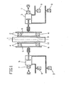
- FIG. 1 an example of an arrangement for carrying out the method according to the invention is shown.
- a metal strip 1, preferably a steel strip 1 is guided on its two sides, or longitudinal sides, by lateral guides.
- Such per se known side guides each comprise a ruler 2, 4.
- the metal strip 1 is contacted by the guide edges 9, 10 of the ruler 2, 4.
- the rulers 2, 4 are preferably made laterally to the belt 1 by drives or adjusting devices 3, 5.
- drives or adjusting devices 3, 5 may be formed, for example, by hydraulic or pneumatic cylinders, as shown.
- Position measuring sensor 7 is provided which can measure the travel of the piston in the adjusting devices 3, 5.
- Positionmessaufêt 7 for example, so that they determine directly in contact with the rulers 2, 4, the position of the rulers.
- contactless position measurements such as with the help of electromagnetic waves.
- Pressure measuring 8, or pressure transducer 8 shown that can measure 3.5 pressure values in a piston-cylinder unit. From these values, it is possible to deduce the forces K1, K2 which act on the rulers 2, 4 according to a known procedure.
- a drive with a motor 3, 5 in particular a rotary motor whose drive torque for determining a force on the rulers 2, 4 are used.
- FIG. 2 a control loop scheme is shown, which is intended to illustrate the inventive method purely by way of example.
- a position control loop for the first ruler 2 is shown, to the right of a position control loop for the second ruler 4.
- the ruler 2 is to be maintained at a desired position S1.
- a fault Z1 acts in the form of a pressure of the belt 1 on the controlled system RS 1 of the control loop, ie on the ruler 2.
- This fault results in a resulting position P1 of the first ruler, which can be determined by the measuring element MG.
- a measuring element can be, for example, the position measuring transducer 7.
- the measured value follows with the setpoint S1 the position of the ruler 2 compared.
- the actuator SG 1 is preferably made by one of the adjusting devices 3, 5 FIG. 1 educated. Alternatively, however, are also electric or rotary motors in question. Finally, the actuator SG 1 again influences the controlled system RS 1 or the ruler 2 and its position.
- the position control loop of the ruler 4 or of the second ruler 4 operates analogously to the control loop just described.
- a disturbance Z2, or a pressure of the metal strip 1 acts on the controlled system RS 2 of the position of the ruler 4.
- This position P2 can be measured by the measuring element MG 2.
- this measured position P2 is compared with a target position S2 of the ruler 4.
- An existing difference between these two values is transferred to the control element RG 2.
- This control element RG 2 is, as usual in control technology, a control value to the actuator SG 2, which thus has an influence on the controlled system RS 2, whereby the control circuit closes.
- the forces K1 measured on the first ruler 2 are compared with the forces K2 measured on the second ruler 4, wherein the smaller of the two forces K1, K2, which is referred to below as the force K ', preferably passed to the controller or control devices R 1 and / or R 2 becomes.
- K1 is the lower force and thus corresponds to the force K '
- this is passed to the controller 1, which outputs a modified setpoint S1 for the position of the first ruler 2.
- This value of the position of the first ruler S1 modified by the force measurement is then compared with the measured position value of the first ruler 2 when the control loop of the first ruler 2 is again passed through.
- the setpoint values S1 and S2 are preferably output by the controllers R1 and R2 in such a way that the smaller of the measured forces K1, K2 or the contact forces K1, K2 lies between a predefinable lower limit or limit force and a predefinable upper limit or limit force.
- the lower limit is preferably chosen so that the friction of the system, or that of the belt 1, can be overcome and thus the control can always have an influence on the movement of the belt 1.
- the upper limit is preferably determined by plant parameters, such as the frictional forces occurring or may also depend on the desired measurement accuracy, depending on the system.
Landscapes
- Engineering & Computer Science (AREA)
- Mechanical Engineering (AREA)
- Registering, Tensioning, Guiding Webs, And Rollers Therefor (AREA)
- Bending Of Plates, Rods, And Pipes (AREA)
- Heat Treatment Of Strip Materials And Filament Materials (AREA)
Claims (8)
- Procédé pour le réglage d'un guidage latéral d'une bande métallique (1), en particulier à l'entrée ou la sortie de cages de laminoir ou d'appareils d'entraînement, dans lequel le guidage latéral comprend, d'un côté de la bande métallique (1), une première règle (2) et de l'autre côté de la bande métallique (1), une deuxième règle (4), dans lequel les règles (2, 4) peuvent être déplacées indépendamment l'une de l'autre et peuvent être entraînées respectivement dans des conditions telles que leur position est réglée, et dans lequel on mesure les forces (K1, K2) de la bande métallique (1) qui s'exercent sur la première règle (2) et sur la deuxième règle (4), caractérisé en ce que l'on règle la position de consigne (S1, S2) pour la première et/ou la deuxième règle (2, 4), en fonction des forces mesurées à la première et à la deuxième règle (2, 4), de telle sorte que la plus petite valeur (K') des forces (K1, K2) mesurées respectivement à la première règle (2) et à la deuxième règle (4), que l'on sélectionne par comparaison entre ces deux forces mesurées (K1, K2), est supérieure à une force limite inférieure sélectionnable et inférieure à une force limite supérieure sélectionnable.
- Procédé selon la revendication 1, dans lequel la force limite supérieure est supérieure à la force limite inférieure, et dans lequel, lorsque la plus petite valeur (K') des forces (K1, K2) mesurées à la première règle (2) et à la deuxième règle (4) dépasse vers le bas la force limite inférieure, on règle les positions pour la première et/ou la deuxième règle (2, 4) de telle sorte que l'on augmente les forces (K1, K2) mesurées à la première règle (2) et à la deuxième règle (4), et dans lequel, lorsque la plus petite valeur (K') des forces (K1, K2) mesurées à la première règle (2) et à la deuxième règle (4) dépasse vers le haut la force limite supérieure, on règle les positions pour la première et/ou pour la deuxième règle (2, 4) de telle sorte que l'on diminue les forces (K1, K2) mesurées à la première et à la deuxième règle (2, 4).
- Procédé selon la revendication 1 ou 2, dans lequel les forces mesurées (K1, K2) sont filtrées et avec un filtre passe-bas.
- Procédé selon l'une quelconque des revendications précédentes, dans lequel la première et la deuxième règle (2, 4) sont entraînées via un entraînement (3, 5) et au moins un de ces entraînements (3, 5) a lieu soit par voie hydraulique, soit par voie pneumatique.
- Procédé selon la revendication 4, dans lequel les entraînements hydrauliques ou pneumatiques (3, 5) comprennent une chambre de cylindre et les forces (K1, K2) qui s'exercent sur la première ou sur la deuxième règle (2, 4) sont déterminées à partir des pressions mesurées dans la chambre de cylindre.
- Procédé selon l'une quelconque des revendications 1 à 3, dans laquelle la première et la deuxième règle (2, 4) sont entraînées via un entraînement (3, 5) et au moins un de ces entraînements a lieu si on le souhaite via un moteur électrique linéaire.
- Procédé selon la revendication 6, dans lequel la force qui s'exerce sur la première ou sur la deuxième règle (2, 4) est déterminée à partir de valeurs électriques mesurées du moteur linéaire.
- Procédé selon l'une quelconque des revendications précédentes, dans lequel la première et la deuxième règle (2, 4) sont entraînées via un entraînement (3, 5) et dans lequel au moins un de ces entraînements a lieu via un moteur rotatif et une transmission à broche, le moteur rotatif étant entraîné soit par voie hydraulique, soit par voie pneumatique.
Applications Claiming Priority (2)
| Application Number | Priority Date | Filing Date | Title |
|---|---|---|---|
| DE102009060826A DE102009060826A1 (de) | 2009-12-29 | 2009-12-29 | Regelung der Seitenführung eines Metallbandes |
| PCT/EP2010/070473 WO2011080174A2 (fr) | 2009-12-29 | 2010-12-22 | Régulation du guide latéral d'une bande métallique |
Publications (2)
| Publication Number | Publication Date |
|---|---|
| EP2519364A2 EP2519364A2 (fr) | 2012-11-07 |
| EP2519364B1 true EP2519364B1 (fr) | 2015-02-25 |
Family
ID=44226877
Family Applications (1)
| Application Number | Title | Priority Date | Filing Date |
|---|---|---|---|
| EP10799027.7A Active EP2519364B1 (fr) | 2009-12-29 | 2010-12-22 | Methode de régulation des guides latéraux d'une bande métallique |
Country Status (8)
| Country | Link |
|---|---|
| US (1) | US8616035B2 (fr) |
| EP (1) | EP2519364B1 (fr) |
| JP (1) | JP5563099B2 (fr) |
| KR (1) | KR101421983B1 (fr) |
| CN (1) | CN102770220B (fr) |
| DE (1) | DE102009060826A1 (fr) |
| RU (1) | RU2524485C2 (fr) |
| WO (1) | WO2011080174A2 (fr) |
Families Citing this family (8)
| Publication number | Priority date | Publication date | Assignee | Title |
|---|---|---|---|---|
| DE102009014099A1 (de) * | 2008-10-28 | 2010-04-29 | Sms Siemag Aktiengesellschaft | Vorrichtung und Verfahren zur seitlichen Führung eines auf einem Rollgang transportierten Walzbandes |
| DE102012224351A1 (de) * | 2012-12-21 | 2014-06-26 | Sms Siemag Ag | Verfahren und Vorrichtung zum Wickeln eines Metallbandes |
| DE102012224505A1 (de) * | 2012-12-28 | 2014-07-03 | Sms Siemag Aktiengesellschaft | Vorrichtung und Verfahren zum seitlichen Führen eines Walz- oder Gießerzeugnisses auf einer Transportstraße |
| DE102013105628A1 (de) * | 2013-05-31 | 2014-12-04 | Sandvik Materials Technology Deutschland Gmbh | Ofenmuffel für einen Glühofen |
| EP3552723A1 (fr) * | 2018-04-12 | 2019-10-16 | Primetals Technologies Austria GmbH | Dispositif et procédé de guidage de bandes métalliques pourvues d'éléments d'usure au moyen de l'élément de support |
| EP3599038A1 (fr) | 2018-07-25 | 2020-01-29 | Primetals Technologies Austria GmbH | Procédé et dispositif de détermination du contour de bande latéral d'une bande métallique en mouvement |
| CN110303482B (zh) * | 2019-07-12 | 2022-03-29 | 大连理工大学 | 一种用于微小多孔零件定心夹持装置 |
| CN111215459A (zh) * | 2019-11-12 | 2020-06-02 | 中冶京诚工程技术有限公司 | 带推板角度可调式推床的轧机区生产设备及热轧生产线 |
Family Cites Families (13)
| Publication number | Priority date | Publication date | Assignee | Title |
|---|---|---|---|---|
| DE3116278A1 (de) * | 1981-04-24 | 1982-11-11 | Betriebsforschungsinstitut VDEh - Institut für angewandte Forschung GmbH, 4000 Düsseldorf | Vorrichtung zum steuern der lage des bandlaufs beim walzen |
| DE3240692A1 (de) * | 1982-11-04 | 1984-05-10 | Mannesmann AG, 4000 Düsseldorf | Hydraulischer antrieb an verschieber- u. zentriereinrichtungen |
| DE3423560A1 (de) * | 1984-06-27 | 1986-01-09 | SMS Schloemann-Siemag AG, 4000 Düsseldorf | Positioniersteuereinrichtung fuer vor dem eingang von warmbreitband-fertigwalzstrassen angeordnete, quer zur walzrichtung verschiebbare fuehrungslineale bzw. fuehrungsrollen |
| JPS61108415A (ja) * | 1984-10-31 | 1986-05-27 | Kawasaki Steel Corp | 熱間連続圧延ラインにおける鋼板サイドガイドの制御方法 |
| JPH02235519A (ja) * | 1989-03-09 | 1990-09-18 | Sumitomo Metal Ind Ltd | ストリップ巻取機のサイドガイドの制御方法 |
| DE3935434A1 (de) * | 1989-10-25 | 1991-05-02 | Schloemann Siemag Ag | Verfahren zur kompensation von durch walzenexzentrizitaeten verursachten stoerungen |
| DE4003717C2 (de) | 1990-02-08 | 1999-05-06 | Schloemann Siemag Ag | Seitenführung für auf einem Rollgang transportiertes Walzband |
| DE19713604A1 (de) * | 1997-04-02 | 1998-10-08 | Schloemann Siemag Ag | Einer Fertigstraße für stranggegossenes Bandmaterial vorgeordnetes positionsgeregeltes Stauchgerüst |
| RU2116146C1 (ru) * | 1997-08-05 | 1998-07-27 | Открытое акционерное общество "Северсталь" | Устройство для центрирования транспортируемой полосы |
| IT1296906B1 (it) * | 1997-12-24 | 1999-08-02 | Abb Sistemi Ind Spa | Dispositivo di regolazione delle guide di ingresso del nastro in un laminatoio |
| DE19915344C2 (de) * | 1999-04-03 | 2001-03-08 | Karl Heess Gmbh & Co Maschb | Wellenricht- und -härtemaschine |
| EP1502673B1 (fr) * | 2003-07-26 | 2006-04-26 | Trumpf Werkzeugmaschinen GmbH + Co. KG | Machine-outil avec un dispositif d'actionnement de l 'outil |
| DE102006058630B4 (de) * | 2006-12-13 | 2012-12-06 | Schuler Pressen Gmbh & Co. Kg | Elektrohydraulische Pressenhaupt- oder Nebenantriebseinrichtung, insbesondere elektrohydraulischer Ziehkissenantrieb |
-
2009
- 2009-12-29 DE DE102009060826A patent/DE102009060826A1/de not_active Withdrawn
-
2010
- 2010-12-22 RU RU2012132395/02A patent/RU2524485C2/ru active
- 2010-12-22 CN CN201080064933.7A patent/CN102770220B/zh active Active
- 2010-12-22 US US13/520,015 patent/US8616035B2/en active Active
- 2010-12-22 JP JP2012546417A patent/JP5563099B2/ja not_active Expired - Fee Related
- 2010-12-22 EP EP10799027.7A patent/EP2519364B1/fr active Active
- 2010-12-22 WO PCT/EP2010/070473 patent/WO2011080174A2/fr active Application Filing
- 2010-12-22 KR KR1020127019719A patent/KR101421983B1/ko active IP Right Grant
Also Published As
| Publication number | Publication date |
|---|---|
| JP5563099B2 (ja) | 2014-07-30 |
| CN102770220A (zh) | 2012-11-07 |
| US20120279267A1 (en) | 2012-11-08 |
| DE102009060826A1 (de) | 2011-06-30 |
| RU2524485C2 (ru) | 2014-07-27 |
| CN102770220B (zh) | 2015-01-28 |
| EP2519364A2 (fr) | 2012-11-07 |
| US8616035B2 (en) | 2013-12-31 |
| WO2011080174A3 (fr) | 2011-12-01 |
| JP2013515615A (ja) | 2013-05-09 |
| RU2012132395A (ru) | 2014-02-10 |
| KR101421983B1 (ko) | 2014-07-22 |
| WO2011080174A2 (fr) | 2011-07-07 |
| KR20120098936A (ko) | 2012-09-05 |
Similar Documents
| Publication | Publication Date | Title |
|---|---|---|
| EP2519364B1 (fr) | Methode de régulation des guides latéraux d'une bande métallique | |
| EP2519365B1 (fr) | Methode de régulation des guides latéraux d'une bande métallique | |
| EP2285506B1 (fr) | Procédé et dispositif de suppression des oscillations dans un système de laminage | |
| WO2013092152A1 (fr) | Procédé et dispositif de refroidissement de cylindres | |
| EP3535069A1 (fr) | Procédé permettant de faire fonctionner une installation mixte de laminage en coulée continue | |
| EP3544751B1 (fr) | Réglage de position de bande consistant à positionner des guides latéraux sur la bande métallique, avec limitation de force | |
| DE112007000641B4 (de) | Kontinuierliche Kaltwalzanlage | |
| AT522234B1 (de) | Verfahren und Vorrichtung zum Geraderichten von Draht oder Bandmaterial | |
| DE3422762C2 (fr) | ||
| DE2828151A1 (de) | Vorrichtung zur steuerung der lage einer walze in ihrer axialen richtung beim walzen eines materials | |
| AT500766A1 (de) | Verfahren und vorrichtung zur vermeidung von schwingungen | |
| DE2608551A1 (de) | Verfahren und einrichtung zum herstellen von gewichts- oder volumengenauen halbzeug-, insbesondere knueppelabschnitten fuer kalt- oder warmverformung | |
| EP2817110B1 (fr) | Procédé de planage comprenant le positionnement du matériau à planer | |
| EP2258492A1 (fr) | Procédé de fabrication d'un produit de laminage à l'aide d'une chaîne de laminage, dispositif de commande et/ou de réglage d'une chaîne de laminage, installation de laminage destinée à la fabrication de produits de laminage laminés, code de programme lisible sur machine et support de stockage | |
| EP2268427B1 (fr) | Procédé d'exploitation pour un train de laminoir à froid avec dynamique améliorée | |
| DE19725726C2 (de) | Verfahren zur Planheitsmessung von Bändern, insbesondere Metallbändern | |
| DE102009014099A1 (de) | Vorrichtung und Verfahren zur seitlichen Führung eines auf einem Rollgang transportierten Walzbandes | |
| DE2657986A1 (de) | Richtmaschine zum richten von blechen und flachmaterialien | |
| DE2261176B2 (de) | Vorrichtung zum Erfassen der Zugspannung von zwischen einzelnen Walzgerüsten eines Walzwerkes laufendem strangförmigen Material und zum Verändern der Geschwindigkeit der Walzen der einzelnen Walzgerüste | |
| DE10159608C5 (de) | Walzverfahren und Walzstraße für ein Band mit einer Schweißnaht | |
| EP4100177B1 (fr) | Procédé d'étalonnage de rouleaux verticaux d'une cage de laminoir vertical et laminoir avec ensemble d'étalonnage pour la mise en oeuvre du procédé | |
| DE3837101A1 (de) | Verfahren zum steuern des bandlaufs beim walzen, in einer walzstrasse | |
| WO2012072603A1 (fr) | Concept de réglage de paramètres d'un processus de laminage au moyen d'un glissement de palier mesuré | |
| EP3487647A1 (fr) | Procédé et dispositif pour cisailler un matériau en tige | |
| DE102021209261A1 (de) | Verfahren zur Steuerung einer Walzgutführung in einer Walzstraße sowie Zwischengerüstführung |
Legal Events
| Date | Code | Title | Description |
|---|---|---|---|
| PUAI | Public reference made under article 153(3) epc to a published international application that has entered the european phase |
Free format text: ORIGINAL CODE: 0009012 |
|
| 17P | Request for examination filed |
Effective date: 20120620 |
|
| AK | Designated contracting states |
Kind code of ref document: A2 Designated state(s): AL AT BE BG CH CY CZ DE DK EE ES FI FR GB GR HR HU IE IS IT LI LT LU LV MC MK MT NL NO PL PT RO RS SE SI SK SM TR |
|
| DAX | Request for extension of the european patent (deleted) | ||
| GRAP | Despatch of communication of intention to grant a patent |
Free format text: ORIGINAL CODE: EPIDOSNIGR1 |
|
| INTG | Intention to grant announced |
Effective date: 20140825 |
|
| GRAP | Despatch of communication of intention to grant a patent |
Free format text: ORIGINAL CODE: EPIDOSNIGR1 |
|
| INTG | Intention to grant announced |
Effective date: 20140923 |
|
| GRAS | Grant fee paid |
Free format text: ORIGINAL CODE: EPIDOSNIGR3 |
|
| GRAA | (expected) grant |
Free format text: ORIGINAL CODE: 0009210 |
|
| AK | Designated contracting states |
Kind code of ref document: B1 Designated state(s): AL AT BE BG CH CY CZ DE DK EE ES FI FR GB GR HR HU IE IS IT LI LT LU LV MC MK MT NL NO PL PT RO RS SE SI SK SM TR |
|
| REG | Reference to a national code |
Ref country code: GB Ref legal event code: FG4D Free format text: NOT ENGLISH |
|
| REG | Reference to a national code |
Ref country code: CH Ref legal event code: EP |
|
| REG | Reference to a national code |
Ref country code: IE Ref legal event code: FG4D Free format text: LANGUAGE OF EP DOCUMENT: GERMAN |
|
| REG | Reference to a national code |
Ref country code: DE Ref legal event code: R096 Ref document number: 502010009012 Country of ref document: DE Effective date: 20150409 |
|
| REG | Reference to a national code |
Ref country code: AT Ref legal event code: REF Ref document number: 711476 Country of ref document: AT Kind code of ref document: T Effective date: 20150415 |
|
| REG | Reference to a national code |
Ref country code: NL Ref legal event code: VDEP Effective date: 20150225 |
|
| REG | Reference to a national code |
Ref country code: LT Ref legal event code: MG4D |
|
| RAP2 | Party data changed (patent owner data changed or rights of a patent transferred) |
Owner name: SMS GROUP GMBH |
|
| PG25 | Lapsed in a contracting state [announced via postgrant information from national office to epo] |
Ref country code: HR Free format text: LAPSE BECAUSE OF FAILURE TO SUBMIT A TRANSLATION OF THE DESCRIPTION OR TO PAY THE FEE WITHIN THE PRESCRIBED TIME-LIMIT Effective date: 20150225 Ref country code: LT Free format text: LAPSE BECAUSE OF FAILURE TO SUBMIT A TRANSLATION OF THE DESCRIPTION OR TO PAY THE FEE WITHIN THE PRESCRIBED TIME-LIMIT Effective date: 20150225 Ref country code: NO Free format text: LAPSE BECAUSE OF FAILURE TO SUBMIT A TRANSLATION OF THE DESCRIPTION OR TO PAY THE FEE WITHIN THE PRESCRIBED TIME-LIMIT Effective date: 20150525 Ref country code: ES Free format text: LAPSE BECAUSE OF FAILURE TO SUBMIT A TRANSLATION OF THE DESCRIPTION OR TO PAY THE FEE WITHIN THE PRESCRIBED TIME-LIMIT Effective date: 20150225 Ref country code: SE Free format text: LAPSE BECAUSE OF FAILURE TO SUBMIT A TRANSLATION OF THE DESCRIPTION OR TO PAY THE FEE WITHIN THE PRESCRIBED TIME-LIMIT Effective date: 20150225 Ref country code: FI Free format text: LAPSE BECAUSE OF FAILURE TO SUBMIT A TRANSLATION OF THE DESCRIPTION OR TO PAY THE FEE WITHIN THE PRESCRIBED TIME-LIMIT Effective date: 20150225 |
|
| REG | Reference to a national code |
Ref country code: DE Ref legal event code: R082 Ref document number: 502010009012 Country of ref document: DE Representative=s name: HEMMERICH & KOLLEGEN, DE Ref country code: DE Ref legal event code: R081 Ref document number: 502010009012 Country of ref document: DE Owner name: SMS GROUP GMBH, DE Free format text: FORMER OWNER: SMS SIEMAG AG, 40237 DUESSELDORF, DE |
|
| PG25 | Lapsed in a contracting state [announced via postgrant information from national office to epo] |
Ref country code: LV Free format text: LAPSE BECAUSE OF FAILURE TO SUBMIT A TRANSLATION OF THE DESCRIPTION OR TO PAY THE FEE WITHIN THE PRESCRIBED TIME-LIMIT Effective date: 20150225 Ref country code: IS Free format text: LAPSE BECAUSE OF FAILURE TO SUBMIT A TRANSLATION OF THE DESCRIPTION OR TO PAY THE FEE WITHIN THE PRESCRIBED TIME-LIMIT Effective date: 20150625 Ref country code: RS Free format text: LAPSE BECAUSE OF FAILURE TO SUBMIT A TRANSLATION OF THE DESCRIPTION OR TO PAY THE FEE WITHIN THE PRESCRIBED TIME-LIMIT Effective date: 20150225 Ref country code: GR Free format text: LAPSE BECAUSE OF FAILURE TO SUBMIT A TRANSLATION OF THE DESCRIPTION OR TO PAY THE FEE WITHIN THE PRESCRIBED TIME-LIMIT Effective date: 20150526 |
|
| PG25 | Lapsed in a contracting state [announced via postgrant information from national office to epo] |
Ref country code: NL Free format text: LAPSE BECAUSE OF FAILURE TO SUBMIT A TRANSLATION OF THE DESCRIPTION OR TO PAY THE FEE WITHIN THE PRESCRIBED TIME-LIMIT Effective date: 20150225 |
|
| PG25 | Lapsed in a contracting state [announced via postgrant information from national office to epo] |
Ref country code: SK Free format text: LAPSE BECAUSE OF FAILURE TO SUBMIT A TRANSLATION OF THE DESCRIPTION OR TO PAY THE FEE WITHIN THE PRESCRIBED TIME-LIMIT Effective date: 20150225 Ref country code: RO Free format text: LAPSE BECAUSE OF FAILURE TO SUBMIT A TRANSLATION OF THE DESCRIPTION OR TO PAY THE FEE WITHIN THE PRESCRIBED TIME-LIMIT Effective date: 20150225 Ref country code: DK Free format text: LAPSE BECAUSE OF FAILURE TO SUBMIT A TRANSLATION OF THE DESCRIPTION OR TO PAY THE FEE WITHIN THE PRESCRIBED TIME-LIMIT Effective date: 20150225 Ref country code: EE Free format text: LAPSE BECAUSE OF FAILURE TO SUBMIT A TRANSLATION OF THE DESCRIPTION OR TO PAY THE FEE WITHIN THE PRESCRIBED TIME-LIMIT Effective date: 20150225 Ref country code: CZ Free format text: LAPSE BECAUSE OF FAILURE TO SUBMIT A TRANSLATION OF THE DESCRIPTION OR TO PAY THE FEE WITHIN THE PRESCRIBED TIME-LIMIT Effective date: 20150225 |
|
| REG | Reference to a national code |
Ref country code: DE Ref legal event code: R097 Ref document number: 502010009012 Country of ref document: DE |
|
| PG25 | Lapsed in a contracting state [announced via postgrant information from national office to epo] |
Ref country code: PL Free format text: LAPSE BECAUSE OF FAILURE TO SUBMIT A TRANSLATION OF THE DESCRIPTION OR TO PAY THE FEE WITHIN THE PRESCRIBED TIME-LIMIT Effective date: 20150225 |
|
| PLBE | No opposition filed within time limit |
Free format text: ORIGINAL CODE: 0009261 |
|
| STAA | Information on the status of an ep patent application or granted ep patent |
Free format text: STATUS: NO OPPOSITION FILED WITHIN TIME LIMIT |
|
| 26N | No opposition filed |
Effective date: 20151126 |
|
| PG25 | Lapsed in a contracting state [announced via postgrant information from national office to epo] |
Ref country code: SI Free format text: LAPSE BECAUSE OF FAILURE TO SUBMIT A TRANSLATION OF THE DESCRIPTION OR TO PAY THE FEE WITHIN THE PRESCRIBED TIME-LIMIT Effective date: 20150225 |
|
| PG25 | Lapsed in a contracting state [announced via postgrant information from national office to epo] |
Ref country code: BE Free format text: LAPSE BECAUSE OF NON-PAYMENT OF DUE FEES Effective date: 20151231 |
|
| PG25 | Lapsed in a contracting state [announced via postgrant information from national office to epo] |
Ref country code: MC Free format text: LAPSE BECAUSE OF FAILURE TO SUBMIT A TRANSLATION OF THE DESCRIPTION OR TO PAY THE FEE WITHIN THE PRESCRIBED TIME-LIMIT Effective date: 20150225 Ref country code: LU Free format text: LAPSE BECAUSE OF FAILURE TO SUBMIT A TRANSLATION OF THE DESCRIPTION OR TO PAY THE FEE WITHIN THE PRESCRIBED TIME-LIMIT Effective date: 20151222 |
|
| REG | Reference to a national code |
Ref country code: CH Ref legal event code: PL |
|
| REG | Reference to a national code |
Ref country code: IE Ref legal event code: MM4A |
|
| REG | Reference to a national code |
Ref country code: FR Ref legal event code: ST Effective date: 20160831 |
|
| PG25 | Lapsed in a contracting state [announced via postgrant information from national office to epo] |
Ref country code: LI Free format text: LAPSE BECAUSE OF NON-PAYMENT OF DUE FEES Effective date: 20151231 Ref country code: CH Free format text: LAPSE BECAUSE OF NON-PAYMENT OF DUE FEES Effective date: 20151231 Ref country code: IE Free format text: LAPSE BECAUSE OF NON-PAYMENT OF DUE FEES Effective date: 20151222 |
|
| PG25 | Lapsed in a contracting state [announced via postgrant information from national office to epo] |
Ref country code: FR Free format text: LAPSE BECAUSE OF NON-PAYMENT OF DUE FEES Effective date: 20151231 |
|
| PG25 | Lapsed in a contracting state [announced via postgrant information from national office to epo] |
Ref country code: SM Free format text: LAPSE BECAUSE OF FAILURE TO SUBMIT A TRANSLATION OF THE DESCRIPTION OR TO PAY THE FEE WITHIN THE PRESCRIBED TIME-LIMIT Effective date: 20150225 Ref country code: HU Free format text: LAPSE BECAUSE OF FAILURE TO SUBMIT A TRANSLATION OF THE DESCRIPTION OR TO PAY THE FEE WITHIN THE PRESCRIBED TIME-LIMIT; INVALID AB INITIO Effective date: 20101222 Ref country code: BG Free format text: LAPSE BECAUSE OF FAILURE TO SUBMIT A TRANSLATION OF THE DESCRIPTION OR TO PAY THE FEE WITHIN THE PRESCRIBED TIME-LIMIT Effective date: 20150225 |
|
| PG25 | Lapsed in a contracting state [announced via postgrant information from national office to epo] |
Ref country code: CY Free format text: LAPSE BECAUSE OF FAILURE TO SUBMIT A TRANSLATION OF THE DESCRIPTION OR TO PAY THE FEE WITHIN THE PRESCRIBED TIME-LIMIT Effective date: 20150225 |
|
| PG25 | Lapsed in a contracting state [announced via postgrant information from national office to epo] |
Ref country code: MT Free format text: LAPSE BECAUSE OF FAILURE TO SUBMIT A TRANSLATION OF THE DESCRIPTION OR TO PAY THE FEE WITHIN THE PRESCRIBED TIME-LIMIT Effective date: 20150225 |
|
| PG25 | Lapsed in a contracting state [announced via postgrant information from national office to epo] |
Ref country code: PT Free format text: LAPSE BECAUSE OF FAILURE TO SUBMIT A TRANSLATION OF THE DESCRIPTION OR TO PAY THE FEE WITHIN THE PRESCRIBED TIME-LIMIT Effective date: 20150225 Ref country code: TR Free format text: LAPSE BECAUSE OF FAILURE TO SUBMIT A TRANSLATION OF THE DESCRIPTION OR TO PAY THE FEE WITHIN THE PRESCRIBED TIME-LIMIT Effective date: 20150225 Ref country code: MK Free format text: LAPSE BECAUSE OF FAILURE TO SUBMIT A TRANSLATION OF THE DESCRIPTION OR TO PAY THE FEE WITHIN THE PRESCRIBED TIME-LIMIT Effective date: 20150225 |
|
| PG25 | Lapsed in a contracting state [announced via postgrant information from national office to epo] |
Ref country code: AL Free format text: LAPSE BECAUSE OF FAILURE TO SUBMIT A TRANSLATION OF THE DESCRIPTION OR TO PAY THE FEE WITHIN THE PRESCRIBED TIME-LIMIT Effective date: 20150225 |
|
| P01 | Opt-out of the competence of the unified patent court (upc) registered |
Effective date: 20230707 |
|
| PGFP | Annual fee paid to national office [announced via postgrant information from national office to epo] |
Ref country code: GB Payment date: 20231220 Year of fee payment: 14 |
|
| PGFP | Annual fee paid to national office [announced via postgrant information from national office to epo] |
Ref country code: IT Payment date: 20231228 Year of fee payment: 14 Ref country code: DE Payment date: 20231214 Year of fee payment: 14 Ref country code: AT Payment date: 20231221 Year of fee payment: 14 |