EP2519364B1 - Method of controlling the side guides of a metal strip - Google Patents
Method of controlling the side guides of a metal strip Download PDFInfo
- Publication number
- EP2519364B1 EP2519364B1 EP10799027.7A EP10799027A EP2519364B1 EP 2519364 B1 EP2519364 B1 EP 2519364B1 EP 10799027 A EP10799027 A EP 10799027A EP 2519364 B1 EP2519364 B1 EP 2519364B1
- Authority
- EP
- European Patent Office
- Prior art keywords
- guide
- forces
- measured
- ruler
- force
- Prior art date
- Legal status (The legal status is an assumption and is not a legal conclusion. Google has not performed a legal analysis and makes no representation as to the accuracy of the status listed.)
- Active
Links
- 238000000034 method Methods 0.000 title claims description 35
- 239000002184 metal Substances 0.000 title claims description 19
- 230000001105 regulatory effect Effects 0.000 claims description 3
- 230000005540 biological transmission Effects 0.000 claims 1
- 230000003247 decreasing effect Effects 0.000 claims 1
- 230000001276 controlling effect Effects 0.000 description 3
- 238000005259 measurement Methods 0.000 description 3
- 238000005516 engineering process Methods 0.000 description 2
- 238000005096 rolling process Methods 0.000 description 2
- 229910000831 Steel Inorganic materials 0.000 description 1
- 238000007664 blowing Methods 0.000 description 1
- 238000006243 chemical reaction Methods 0.000 description 1
- 230000008878 coupling Effects 0.000 description 1
- 238000010168 coupling process Methods 0.000 description 1
- 238000005859 coupling reaction Methods 0.000 description 1
- 230000002950 deficient Effects 0.000 description 1
- 238000001914 filtration Methods 0.000 description 1
- 239000000463 material Substances 0.000 description 1
- 239000010959 steel Substances 0.000 description 1
Images

Classifications
-
- B—PERFORMING OPERATIONS; TRANSPORTING
- B21—MECHANICAL METAL-WORKING WITHOUT ESSENTIALLY REMOVING MATERIAL; PUNCHING METAL
- B21C—MANUFACTURE OF METAL SHEETS, WIRE, RODS, TUBES OR PROFILES, OTHERWISE THAN BY ROLLING; AUXILIARY OPERATIONS USED IN CONNECTION WITH METAL-WORKING WITHOUT ESSENTIALLY REMOVING MATERIAL
- B21C47/00—Winding-up, coiling or winding-off metal wire, metal band or other flexible metal material characterised by features relevant to metal processing only
- B21C47/34—Feeding or guiding devices not specially adapted to a particular type of apparatus
-
- B—PERFORMING OPERATIONS; TRANSPORTING
- B21—MECHANICAL METAL-WORKING WITHOUT ESSENTIALLY REMOVING MATERIAL; PUNCHING METAL
- B21B—ROLLING OF METAL
- B21B37/00—Control devices or methods specially adapted for metal-rolling mills or the work produced thereby
- B21B37/68—Camber or steering control for strip, sheets or plates, e.g. preventing meandering
-
- B—PERFORMING OPERATIONS; TRANSPORTING
- B21—MECHANICAL METAL-WORKING WITHOUT ESSENTIALLY REMOVING MATERIAL; PUNCHING METAL
- B21D—WORKING OR PROCESSING OF SHEET METAL OR METAL TUBES, RODS OR PROFILES WITHOUT ESSENTIALLY REMOVING MATERIAL; PUNCHING METAL
- B21D43/00—Feeding, positioning or storing devices combined with, or arranged in, or specially adapted for use in connection with, apparatus for working or processing sheet metal, metal tubes or metal profiles; Associations therewith of cutting devices
- B21D43/02—Advancing work in relation to the stroke of the die or tool
- B21D43/021—Control or correction devices in association with moving strips
- B21D43/023—Centering devices, e.g. edge guiding
-
- B—PERFORMING OPERATIONS; TRANSPORTING
- B21—MECHANICAL METAL-WORKING WITHOUT ESSENTIALLY REMOVING MATERIAL; PUNCHING METAL
- B21B—ROLLING OF METAL
- B21B39/00—Arrangements for moving, supporting, or positioning work, or controlling its movement, combined with or arranged in, or specially adapted for use in connection with, metal-rolling mills
- B21B39/14—Guiding, positioning or aligning work
Definitions
- the invention relates to a method for controlling side guides of a metal strip, in particular in rolling plants according to the preamble of claim 1 (see, for example, US Pat. DE 698 29 454 T ), for example in the inlet or outlet of rolling mills or before blowing apparatus or in other belt processing lines.
- a ruler is operated position-controlled while guiding a band, while the other ruler is pressed against the band with a defined force.
- the determination of the contact force between ruler and belt is carried out in this method for both sides.
- the ruler While guiding the tape, the ruler on one Position-controlled held on a fixed position.
- the other ruler is force-controlled with a defined force pressed against the belt.
- the nominal force of the force-controlled ruler is fixed depending on the characteristics of the belt to be led such as material, width, thickness, temperature or speed.
- This target force is chosen such that it is greater than the contact force of the band on the force-controlled side in any case, otherwise the guide could be opened on this side of the band.
- a disadvantage of this method is that when the band exerts a force on the position-controlled side, both this reaction force and, in addition, the predetermined force of the force-regulated side must be recorded on this side. Damage to the band and also to the rulers are the result. To repair the rulers, long plant downtimes are unavoidable.
- another disadvantage of this method results from the fact that the width of the tape to be fed is generally not constant. By specifying a fixed target force regardless of the width of the tape to be led the rulers can not be adjusted to different bandwidth gradients, so at best the leadership is deficient or such high forces between band and rulers that considerable damage occurs.
- the publication DE 4003717 A1 discloses another method for side guidance of a rolled strip.
- the object of the disclosed method is to increase the service life of the guide rulers in a roller table.
- a regulation of the guide rulers is proposed, which operates in such a way that they can be pressed against the strip edges alternately and then lifted off from them again.
- a disadvantage of this method is, inter alia, that setpoints for a force control loop are predetermined by a process computer according to an input and thereby the control can not run sufficiently accurate in many cases. Due to the predetermined desired forces, this method also has the above-mentioned disadvantages, so that the rulers still wear unsatisfactorily fast by this method and also significant band edge damage can occur.
- the invention is defined by the defined in claim 1 method for controlling a side guide of a metal strip, wherein the side guide on one side of the metal strip comprises a first and on the other side of the metal strip a second ruler, the rulers can be moved independently and each operated position-controlled and forces of the metal strip, which act on the first and on the second ruler, are measured and according to the invention, the target position for the first and / or the second ruler is controlled depending on the forces measured on the first and on the second ruler forces in that only the smaller value of the forces measured on the first and second ruler is above a selectable lower limit force and below a selectable upper limit force.
- both rulers are operated position-controlled independently of each other and that the forces measured at the rulers are used for the determination of the desired position as described, reduces damage to the rulers.
- the control of the invention proves to be extremely advantageous.
- the control according to the invention is also particularly advantageous when width variations of the band occur.
- the upper limit force is greater than the lower limit force.
- this embodiment comprises the feature that when the smaller value of the forces measured on the first ruler and the second ruler falls below the lower limit force, the positions for the first and / or second ruler are adjusted such that the forces measured at the first and at the second ruler are increased.
- the positions for the first and / or second ruler are adjusted so that those at the first and second rulers measured forces are lowered. If this is done in a controlled manner, the forces between the belt and the rulers are particularly effectively reduced, which reduces the wear on the rulers and prevents damage to the rulers even more effectively.
- the measured forces are filtered with a low-pass filter. Due to the low-pass filtering, the process can work reliably and insensitive. High frequencies, which are often due to interference, can be filtered out in this way.
- the first and the second ruler are driven by a drive, wherein at least one of these drives is either hydraulically or pneumatically.
- the hydraulic or pneumatic drives comprise two cylinder chambers, wherein the forces acting on the first or on the second ruler are determined from the pressures measured in the cylinder chambers.
- the first and the second ruler are driven by a drive, wherein at least one of these drives is optionally effected by an electric linear motor.
- the force acting on the first or the second ruler is determined from measured electrical variables of the linear motor.
- the first and the second ruler are driven by a drive, wherein at least one of these drives via a rotary motor and a spindle gear and wherein the rotary motor is selectively driven hydraulically or pneumatically.
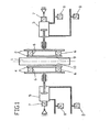
- FIG. 1 an example of an arrangement for carrying out the method according to the invention is shown.
- a metal strip 1, preferably a steel strip 1 is guided on its two sides, or longitudinal sides, by lateral guides.
- Such per se known side guides each comprise a ruler 2, 4.
- the metal strip 1 is contacted by the guide edges 9, 10 of the ruler 2, 4.
- the rulers 2, 4 are preferably made laterally to the belt 1 by drives or adjusting devices 3, 5.
- drives or adjusting devices 3, 5 may be formed, for example, by hydraulic or pneumatic cylinders, as shown.
- Position measuring sensor 7 is provided which can measure the travel of the piston in the adjusting devices 3, 5.
- Positionmessaufêt 7 for example, so that they determine directly in contact with the rulers 2, 4, the position of the rulers.
- contactless position measurements such as with the help of electromagnetic waves.
- Pressure measuring 8, or pressure transducer 8 shown that can measure 3.5 pressure values in a piston-cylinder unit. From these values, it is possible to deduce the forces K1, K2 which act on the rulers 2, 4 according to a known procedure.
- a drive with a motor 3, 5 in particular a rotary motor whose drive torque for determining a force on the rulers 2, 4 are used.
- FIG. 2 a control loop scheme is shown, which is intended to illustrate the inventive method purely by way of example.
- a position control loop for the first ruler 2 is shown, to the right of a position control loop for the second ruler 4.
- the ruler 2 is to be maintained at a desired position S1.
- a fault Z1 acts in the form of a pressure of the belt 1 on the controlled system RS 1 of the control loop, ie on the ruler 2.
- This fault results in a resulting position P1 of the first ruler, which can be determined by the measuring element MG.
- a measuring element can be, for example, the position measuring transducer 7.
- the measured value follows with the setpoint S1 the position of the ruler 2 compared.
- the actuator SG 1 is preferably made by one of the adjusting devices 3, 5 FIG. 1 educated. Alternatively, however, are also electric or rotary motors in question. Finally, the actuator SG 1 again influences the controlled system RS 1 or the ruler 2 and its position.
- the position control loop of the ruler 4 or of the second ruler 4 operates analogously to the control loop just described.
- a disturbance Z2, or a pressure of the metal strip 1 acts on the controlled system RS 2 of the position of the ruler 4.
- This position P2 can be measured by the measuring element MG 2.
- this measured position P2 is compared with a target position S2 of the ruler 4.
- An existing difference between these two values is transferred to the control element RG 2.
- This control element RG 2 is, as usual in control technology, a control value to the actuator SG 2, which thus has an influence on the controlled system RS 2, whereby the control circuit closes.
- the forces K1 measured on the first ruler 2 are compared with the forces K2 measured on the second ruler 4, wherein the smaller of the two forces K1, K2, which is referred to below as the force K ', preferably passed to the controller or control devices R 1 and / or R 2 becomes.
- K1 is the lower force and thus corresponds to the force K '
- this is passed to the controller 1, which outputs a modified setpoint S1 for the position of the first ruler 2.
- This value of the position of the first ruler S1 modified by the force measurement is then compared with the measured position value of the first ruler 2 when the control loop of the first ruler 2 is again passed through.
- the setpoint values S1 and S2 are preferably output by the controllers R1 and R2 in such a way that the smaller of the measured forces K1, K2 or the contact forces K1, K2 lies between a predefinable lower limit or limit force and a predefinable upper limit or limit force.
- the lower limit is preferably chosen so that the friction of the system, or that of the belt 1, can be overcome and thus the control can always have an influence on the movement of the belt 1.
- the upper limit is preferably determined by plant parameters, such as the frictional forces occurring or may also depend on the desired measurement accuracy, depending on the system.
Description
Die Erfindung betrifft ein Verfahren zur Regelung von Seitenführungen eines Metallbandes, insbesondere in Walzanlagen gemäß dem Oberbegriff des Anspruchs 1 (siehe, z.B.,
Aus dem Stand der Technik sind bereits Verfahren zur Regelung von Seitenführungen eines Metallbandes bekannt. Solche Führungen bestehen in der Regel aus zwei seitlich zum Weg des Bandes angeordneten Linealen, die mit Hydraulikzylindern positioniert und bei Durchlauf eines Bandes an das Band angedrückt bzw. angestellt werden können. Häufig weisen die bekannten Systeme eine mechanische Kopplung beider Lineale, wie auch eine gemeinsame Regelung für deren Verstellung, auf. Zwar sind derartige Systeme relativ einfach zu konzeptionieren, jedoch sind deren Verstellmöglichkeiten und insbesondere deren Regelung sehr eingeschränkt. Nicht alle Bandverläufe können hinreichend korrigiert werden. Schäden an den Metallbändern und an den Linealen sind nicht immer hinreichend zu vermeiden.Methods for controlling side guides of a metal strip are already known from the prior art. Such guides usually consist of two laterally arranged to the path of the tape rulers, which can be positioned with hydraulic cylinders and pressed or employed in the passage of a tape to the tape. Frequently, the known systems have a mechanical coupling of both rulers, as well as a common control for the adjustment on. Although such systems are relatively easy to conceptualize, but their adjustment options and in particular their control are very limited. Not all band progressions can be sufficiently corrected. Damage to the metal bands and rulers is not always to be avoided sufficiently.
Weiterhin sind Verfahren bekannt, bei denen während des Führens eines Bandes ein Lineal positionsgeregelt betrieben wird, während das andere Lineal mit einer definierten Kraft an das Band angedrückt wird. Die Bestimmung der Anpresskraft zwischen Lineal und Band wird bei dieser Methode für beide Seiten durchgeführt. Während des Führens des Bandes wird dabei das Lineal auf einer Seite positionsgeregelt auf einer festen Position gehalten. Das andere Lineal wird kraftgeregelt mit einer definierten Kraft an das Band angedrückt. Die Sollkraft des kraftgeregelten Lineals wird abhängig von den Eigenschaften des zu führenden Bandes wie Material, Breite, Dicke, Temperatur oder Geschwindigkeit fest vorgegeben. Diese Sollkraft wird derart gewählt, dass sie in jedem Falle größer als die Kontaktkraft des Bandes auf die kraftgeregelte Seite ist, da sonst die Führung auf dieser Seite von dem Band geöffnet werden könnte. Ein Nachteil dieser Methode besteht darin, dass wenn das Band auf die positionsgeregelte Seite eine Kraft ausübt, auf dieser Seite sowohl diese Reaktionskraft und zusätzlich die vorgegebene Kraft der kraftgeregelten Seite aufgenommen werden muss. Schäden am Band und auch an den Linealen sind die Folge. Zur Instandsetzung der Lineale sind somit lange Anlagenstillstände unvermeidbar. Zudem ergibt sich ein weiterer Nachteil dieses Verfahrens daraus, dass die Breite des zu führenden Bandes im Allgemeinen nicht konstant ist. Durch die Vorgabe einer festen Sollkraft unabhängig von der Breite des zu führenden Bandes können die Lineale nicht angemessen an verschiedene Bandbreitenverläufe angestellt werden, wodurch bestenfalls die Führung mangelhaft ist oder derart hohe Kräfte zwischen Band und Linealen wirken, dass erhebliche Schäden auftreten.Furthermore, methods are known in which a ruler is operated position-controlled while guiding a band, while the other ruler is pressed against the band with a defined force. The determination of the contact force between ruler and belt is carried out in this method for both sides. While guiding the tape, the ruler on one Position-controlled held on a fixed position. The other ruler is force-controlled with a defined force pressed against the belt. The nominal force of the force-controlled ruler is fixed depending on the characteristics of the belt to be led such as material, width, thickness, temperature or speed. This target force is chosen such that it is greater than the contact force of the band on the force-controlled side in any case, otherwise the guide could be opened on this side of the band. A disadvantage of this method is that when the band exerts a force on the position-controlled side, both this reaction force and, in addition, the predetermined force of the force-regulated side must be recorded on this side. Damage to the band and also to the rulers are the result. To repair the rulers, long plant downtimes are unavoidable. In addition, another disadvantage of this method results from the fact that the width of the tape to be fed is generally not constant. By specifying a fixed target force regardless of the width of the tape to be led the rulers can not be adjusted to different bandwidth gradients, so at best the leadership is deficient or such high forces between band and rulers that considerable damage occurs.
Die Offenlegungsschrift
Die technische Aufgabe, welche sich aus dem Stand der Technik ergibt, ist folglich darin zu sehen, ein verbessertes Regelungsverfahren für Seitenführungen von Metallbändern zur Verfügung zu stellen oder zumindest einen der oben genannten Nachteile zu vermeiden.The technical task, which results from the prior art, is therefore to be seen to provide an improved control method for side guides of metal bands available or at least to avoid one of the above-mentioned disadvantages.
Die Erfindung wird durch das im Anspruch 1 definierte Verfahren zur Regelung einer Seitenführung eines Metallbandes definiert, wobei die Seitenführung auf einer Seite der Metallbandes ein erstes und auf der anderen Seite des Metallbandes ein zweites Lineal umfasst, wobei die Lineale unabhängig voneinander bewegt werden können und jeweils positionsgeregelt betrieben werden und Kräfte des Metallbandes, die auf das erste und auf das zweite Lineal wirken, gemessen werden und erfindungsgemäß die Sollposition für das erste und/oder das zweite Lineal abhängig von den an dem ersten und an dem zweiten Lineal gemessen Kräften derart geregelt wird, dass nur der kleinere Wert der jeweils am ersten und am zweiten Lineal gemessenen Kräfte, oberhalb einer wählbaren unteren Grenzkraft und unterhalb einer wählbaren oberen Grenzkraft liegt. Dadurch, dass beide Lineale unabhängig voneinander positionsgeregelt betrieben werden und dadurch, dass die an den Linealen gemessenen Kräfte für die Bestimmung der Sollposition wie beschrieben eingesetzt werden, werden Schäden an den Linealen reduziert. Insbesondere bei schwergängigen Führungen erweist sich die erfindungsgemäße Regelung als äußerst vorteilhaft. Die erfindungsgemäße Regelung ist zudem besonders vorteilhaft, wenn Breitenschwankungen des Bandes auftreten.The invention is defined by the defined in
In einer bevorzugten Ausführungsform des erfindungsgemäßen Verfahrens ist die obere Grenzkraft grösser als die untere Grenzkraft. Weiterhin umfasst diese Ausführungsform das Merkmal, dass wenn der kleinere Wert, der am ersten Lineal und am zweiten Lineal gemessenen Kräfte, die untere Grenzkraft unterschreitet, die Positionen für das erste und/oder das zweite Lineal derart verstellt werden, dass die an dem ersten und die an dem zweiten Lineal gemessenen Kräfte erhöht werden. Darüberhinaus gilt, dass wenn der kleinere Wert, der am ersten Lineal und am zweiten Lineal gemessenen Kräfte die obere Grenzkraft überschreitet, die Positionen für das erste und/oder das zweite Lineal derart verstellt werden, dass die an dem ersten und die an dem zweiten Lineal gemessenen Kräfte erniedrigt werden. Läuft die Regelung derart ab, werden die Kräfte zwischen Band und Linealen besonders effektiv reduziert, wodurch der Verschleiß der Lineale reduziert wird und Schäden an diesen noch wirksamer vermieden werden.In a preferred embodiment of the method according to the invention, the upper limit force is greater than the lower limit force. Furthermore, this embodiment comprises the feature that when the smaller value of the forces measured on the first ruler and the second ruler falls below the lower limit force, the positions for the first and / or second ruler are adjusted such that the forces measured at the first and at the second ruler are increased. In addition, when the smaller value of the forces measured on the first ruler and the second ruler exceeds the upper limit force, the positions for the first and / or second ruler are adjusted so that those at the first and second rulers measured forces are lowered. If this is done in a controlled manner, the forces between the belt and the rulers are particularly effectively reduced, which reduces the wear on the rulers and prevents damage to the rulers even more effectively.
In einer weiteren bevorzugten Ausführungsform des erfindungsgemäßen Verfahrens werden die gemessenen Kräfte mit einem Tiefpassfilter gefiltert. Durch die Tiefpassfilterung kann das Verfahren zuverlässig und unempfindlich arbeiten. Hohe Frequenzen, die häufig auf Störungen zurückgehen, können so herausgefiltert werden.In a further preferred embodiment of the method according to the invention, the measured forces are filtered with a low-pass filter. Due to the low-pass filtering, the process can work reliably and insensitive. High frequencies, which are often due to interference, can be filtered out in this way.
In einer weiteren Ausführungsform des erfindungsgemäßen Verfahrens werden das erste und das zweite Lineal durch einen Antrieb angetrieben, wobei mindestens einer dieser Antriebe wahlweise hydraulisch oder pneumatisch erfolgt.In a further embodiment of the method according to the invention, the first and the second ruler are driven by a drive, wherein at least one of these drives is either hydraulically or pneumatically.
In einer weiteren Ausführungsform des erfindungsgemäßen Verfahrens umfassen die hydraulischen oder pneumatischen Antriebe zwei Zylinderkammern, wobei die auf das erste oder die auf das zweite Lineal wirkenden Kräfte, aus den in den Zylinderkammern gemessenen Drücken bestimmt werden.In a further embodiment of the method according to the invention, the hydraulic or pneumatic drives comprise two cylinder chambers, wherein the forces acting on the first or on the second ruler are determined from the pressures measured in the cylinder chambers.
In einer weiteren Ausführungsform des erfindungsgemäßen Verfahrens werden das erste und das zweite Lineal durch einen Antrieb angetrieben, wobei mindestens einer dieser Antriebe wahlweise durch einen elektrischen Linearmotor erfolgt.In a further embodiment of the method according to the invention, the first and the second ruler are driven by a drive, wherein at least one of these drives is optionally effected by an electric linear motor.
In einer weiteren Ausführungsform des erfindungsgemäßen Verfahrens wird die Kraft, die auf das erste oder das zweite Lineal wirkt, aus gemessenen elektrischen Größen des Linearmotors bestimmt.In a further embodiment of the method according to the invention, the force acting on the first or the second ruler is determined from measured electrical variables of the linear motor.
In einer weiteren Ausführungsform des erfindungsgemäßen Verfahrens werden das erste und das zweite Lineal durch einen Antrieb angetrieben, wobei mindestens einer dieser Antriebe über einen rotatorischen Motor und ein Spindelgetriebe erfolgt und wobei der rotatorische Motor wahlweise hydraulisch oder pneumatisch angetrieben wird.In a further embodiment of the method according to the invention, the first and the second ruler are driven by a drive, wherein at least one of these drives via a rotary motor and a spindle gear and wherein the rotary motor is selectively driven hydraulically or pneumatically.
Im Folgenden werden kurz die Figuren der Ausführungsbeispiele beschrieben. Weitere Details sind der detaillierten Beschreibung der Ausführungsbeispiele zu entnehmen.The figures of the embodiments will be briefly described below. Further details can be found in the detailed description of the embodiments.
Es zeigen:
Figur 1- eine Schemaskizze einer Seitenführung eines Metallbandes samt Steuer- und Regeltechnik; und
Figur 2- ein Regelschema.
- FIG. 1
- a schematic of a side guide of a metal strip together with control and regulation technology; and
- FIG. 2
- a rule scheme.
In
In
Analog zu dem gerade beschriebenen Regelkreis arbeitet der Positionsregelkreis des Lineals 4 bzw. des zweiten Lineals 4. Auf die Regelstrecke RS 2 der Position des Lineals 4 wirkt eine Störgröße Z2, bzw. ein Druck des Metallbandes 1. Insgesamt stellt sich die Position P2 des Lineals 4 ein. Diese Position P2 kann durch das Messglied MG 2 gemessen werden. Nachfolgend wird diese gemessene Position P2 mit einer Sollposition S2 des Lineals 4 verglichen. Eine bestehende Differenz zwischen diesen beiden Werten wird an das Regelglied RG 2 übergeben. Dieses Regelglied RG 2 gibt, wie in der Regelungstechnik üblich, einen Stellwert an das Stellglied SG 2 aus, welches somit Einfluss auf die Regelstrecke RS 2 nimmt, wodurch sich der Regelkreis schließt.The position control loop of the
Erfindungsgemäß werden zusätzlich zu der Positionsregelung auf beiden Seiten des Metallbandes 1 auch die Kräfte gemessen, die auf die Lineale 2, 4 wirken. Das heißt insbesondere, dass zu jeder Position P1 eine Kraft K1 existiert und dass zu jeder Position P2 auch eine Kraft K2 existiert. Diese Kräfte K1, K2 sind ebenfalls in
- 11
- Metallbandmetal band
- 22
- erstes Linealfirst ruler
- 33
- erste Anstellvorrichtungfirst adjusting device
- 44
- zweites Linealsecond ruler
- 55
- zweite Anstellvorrichtungsecond adjusting device
- 66
- Kraftmessaufnehmerload cells
- 77
- PositionsmessaufnehmerPositionsmessaufnehmer
- 88th
- Druckmessaufnehmerpressure transducers
- 99
- erste Führungskantefirst leading edge
- 1010
- zweite Führungskantesecond leading edge
- K1K1
- Am ersten Lineal vorliegende KraftPower present on the first ruler
- K2K2
- Am zweiten Lineal vorliegende KraftPower present on the second ruler
- K'K '
- kleinere der gemessenen Kräfte K1, K2smaller of the measured forces K1, K2
-
MG 1
MG 1 - Positionsmessgerät des ersten LinealsPosition measuring device of the first ruler
-
MG 2
MG 2 - Positionsmessgerät des zweiten LinealsPosition measuring device of the second ruler
- MG 1'MG 1 '
- Kraftmessgerät des ersten LinealsForce gauge of the first ruler
- MG 2'MG 2 '
- Kraftmessgerät des zweiten LinealsForce gauge of the second ruler
- P1P1
- Position des ersten LinealsPosition of the first ruler
- P2P2
- Position des zweiten LinealsPosition of the second ruler
-
R 1
R 1 -
Regler 1 für die Ausgabe des Positionssollwertes S1 für das erste Lineal
Controller 1 for the output of the position setpoint S1 for the first ruler -
R 2
R 2 -
Regler 2 für die Ausgabe des Positionssollwertes S2 für das zweite Lineal
Controller 2 for the output of the position setpoint S2 for the second ruler -
RG 1
RG 1 - Regelglied des Positionsregelkreises des ersten LinealsControl element of the position control loop of the first ruler
-
RG 2
RG 2 - Regelglied des Positionsregelkreises des zweiten LinealsControl element of the position control loop of the second ruler
-
RS 1
RS 1 - Regelstrecke des Positionsregelkreises des ersten LinealsControlled system of the position control loop of the first ruler
-
RS 2
RS 2 - Regelstrecke des Positionsregelkreises des zweiten LinealsControlled system of the position control loop of the second ruler
- S1S1
- Sollwert für die Position des ersten LinealsSetpoint for the position of the first ruler
- S2S2
- Sollwert für die Position des zweiten LinealsSetpoint for the position of the second ruler
-
SG 1
SG 1 - Stellglied des Positionsregelkreises des ersten LinealsActuator of the position control loop of the first ruler
-
SG 2
SG 2 - Stellglied des Positionsregelkreises des zweiten LinealsActuator of the position control loop of the second ruler
- Z1Z1
- Störung des Positionsregelkreises des ersten LinealsDisturbance of the position control loop of the first ruler
- Z2Z2
- Störung des Positionsregelkreises des zweiten LinealsDisturbance of the position control loop of the second ruler
Claims (8)
- Method of regulating a lateral guide of a metal strip (1), particularly in the inlet or outlet of roll stands or in front of drive apparatus, wherein the lateral guide comprises a first guide (2) on one side of the metal strip (1) and a second guide (4) on the other side of the metal strip (1), wherein the guides (2, 4) can be moved independently of one another and each can be operated under positional regulation and wherein forces K1, K2), which act on the first guide (2) and on the second guide (4), of the metal strip (1) can be measured,
characterised in that
the target position (S1, S2) for the first and/or the second guide (2, 4) is so regulated in dependence on the forces (K1, K2) measured at the first and the second guide (2, 4) that the lower value (K') of the forces (K1, K2) respectively measured at the first guide (2) and at the second guide (4), which lower value is selected by comparison between these two measured forces (K1, K2), lies above a selectable lower limit force and below a selectable upper limit force. - Method according to claim 1, wherein the upper limit force is greater than the lower limit force and wherein if the lower value (K') of the forces (K1, K2) measured at the first guide (2) and at the second guide (4) falls below the lower limit force the positions for the first and/or second guide (2, 4) are so adjusted that the forces (K1, K2) measured at the first and the second guide (2, 4) are increased and if the lower value (K') of the forces (K1, K2) measured at the first guide (2) and at the second guide (4) exceeds the upper limit force the positions for the first and/or second guide (2, 4) are so adjusted that the forces (K1, K2) measured at the first and the second guide (2, 4) are decreased.
- Method according to claim 1 or 2, wherein the measured forces (K1, K2) are filtered by a low-pass filter.
- Method according to any one of the preceding claims, wherein the first and the second guides (2, 4) are driven by a drive (3, 5) and at least one of these drives (3, 5) is realised selectably hydraulically or pneumatically.
- Method according to claim 4, wherein the hydraulic or pneumatic drives (3, 5) comprise a cylinder chamber and the forces (K1, K2) acting on the first or second guide (2, 4) are determined from the pressures measured in the cylinder chamber.
- Method according to any one of claims 1 to 3, wherein the first and the second guides (2, 4) are driven by a drive (3, 5) and at least one of these drives (3, 5) is realised selectably by an electric linear motor.
- Method according to claim 6, wherein the force acting on the first or second guide (2, 4) is determined from measured electrical variables of the linear motor.
- Method according to any one of the preceding claims, wherein the first and the second guides (2, 4) are driven by a drive (3, 5) and wherein at least one of these drives is realised by way of a rotary motor and a spindle transmission, wherein the rotary motor is driven selectably hydraulically or pneumatically.
Applications Claiming Priority (2)
| Application Number | Priority Date | Filing Date | Title |
|---|---|---|---|
| DE102009060826A DE102009060826A1 (en) | 2009-12-29 | 2009-12-29 | Regulation of the lateral guidance of a metal strip |
| PCT/EP2010/070473 WO2011080174A2 (en) | 2009-12-29 | 2010-12-22 | Controlling the side guide of a metal strip |
Publications (2)
| Publication Number | Publication Date |
|---|---|
| EP2519364A2 EP2519364A2 (en) | 2012-11-07 |
| EP2519364B1 true EP2519364B1 (en) | 2015-02-25 |
Family
ID=44226877
Family Applications (1)
| Application Number | Title | Priority Date | Filing Date |
|---|---|---|---|
| EP10799027.7A Active EP2519364B1 (en) | 2009-12-29 | 2010-12-22 | Method of controlling the side guides of a metal strip |
Country Status (8)
| Country | Link |
|---|---|
| US (1) | US8616035B2 (en) |
| EP (1) | EP2519364B1 (en) |
| JP (1) | JP5563099B2 (en) |
| KR (1) | KR101421983B1 (en) |
| CN (1) | CN102770220B (en) |
| DE (1) | DE102009060826A1 (en) |
| RU (1) | RU2524485C2 (en) |
| WO (1) | WO2011080174A2 (en) |
Families Citing this family (8)
| Publication number | Priority date | Publication date | Assignee | Title |
|---|---|---|---|---|
| DE102009014099A1 (en) * | 2008-10-28 | 2010-04-29 | Sms Siemag Aktiengesellschaft | Device and method for lateral guidance of a rolled strip transported on a roller table |
| DE102012224351A1 (en) * | 2012-12-21 | 2014-06-26 | Sms Siemag Ag | Method and device for winding a metal strip |
| DE102012224505A1 (en) | 2012-12-28 | 2014-07-03 | Sms Siemag Aktiengesellschaft | Apparatus and method for laterally guiding a rolled or cast product on a transport line |
| DE102013105628A1 (en) * | 2013-05-31 | 2014-12-04 | Sandvik Materials Technology Deutschland Gmbh | Furnace muffle for an annealing furnace |
| EP3552723A1 (en) * | 2018-04-12 | 2019-10-16 | Primetals Technologies Austria GmbH | Device and method for guiding metal strips with grinding bodies having a carrier member |
| EP3599038A1 (en) * | 2018-07-25 | 2020-01-29 | Primetals Technologies Austria GmbH | Method and device for determining the lateral contour of a running metal strip |
| CN110303482B (en) * | 2019-07-12 | 2022-03-29 | 大连理工大学 | Centering and clamping device for micro porous parts |
| CN111215459A (en) * | 2019-11-12 | 2020-06-02 | 中冶京诚工程技术有限公司 | Rolling mill area production equipment with push plate angle-adjustable push bed and hot rolling production line |
Family Cites Families (13)
| Publication number | Priority date | Publication date | Assignee | Title |
|---|---|---|---|---|
| DE3116278A1 (en) * | 1981-04-24 | 1982-11-11 | Betriebsforschungsinstitut VDEh - Institut für angewandte Forschung GmbH, 4000 Düsseldorf | DEVICE FOR CONTROLLING THE POSITION OF THE TAPE ROLL WHILE ROLLING |
| DE3240692A1 (en) * | 1982-11-04 | 1984-05-10 | Mannesmann AG, 4000 Düsseldorf | Hydraulic drive on displacing and centring devices |
| DE3423560A1 (en) * | 1984-06-27 | 1986-01-09 | SMS Schloemann-Siemag AG, 4000 Düsseldorf | POSITIONING CONTROL DEVICE FOR BEFORE THE INPUT OF WARM BROADBAND FINISHING ROLLING MILLS, CROSS-SLIDING GUIDE LINEAL OR. LEADERSHIP ROLES |
| JPS61108415A (en) | 1984-10-31 | 1986-05-27 | Kawasaki Steel Corp | Method for controlling side guide of steel sheet in hot continuous rolling line |
| JPH02235519A (en) * | 1989-03-09 | 1990-09-18 | Sumitomo Metal Ind Ltd | Method for controlling side guide of strip coiler |
| DE3935434A1 (en) * | 1989-10-25 | 1991-05-02 | Schloemann Siemag Ag | METHOD FOR COMPENSATING DISTURBANCES CAUSED BY ROLLER Eccentricities |
| DE4003717C2 (en) | 1990-02-08 | 1999-05-06 | Schloemann Siemag Ag | Lateral guide for rolled strip transported on a roller table |
| DE19713604A1 (en) * | 1997-04-02 | 1998-10-08 | Schloemann Siemag Ag | A position-controlled compression frame arranged upstream of a finishing train for continuously cast strip material |
| RU2116146C1 (en) * | 1997-08-05 | 1998-07-27 | Открытое акционерное общество "Северсталь" | Apparatus for centering transported strip |
| IT1296906B1 (en) * | 1997-12-24 | 1999-08-02 | Abb Sistemi Ind Spa | DEVICE FOR ADJUSTING THE TAPE INPUT GUIDES IN A ROLLING MILL |
| DE19915344C2 (en) * | 1999-04-03 | 2001-03-08 | Karl Heess Gmbh & Co Maschb | Shaft straightening and hardening machine |
| EP1502673B1 (en) * | 2003-07-26 | 2006-04-26 | Trumpf Werkzeugmaschinen GmbH + Co. KG | Machine tool with driving means for the tool |
| DE102006058630B4 (en) * | 2006-12-13 | 2012-12-06 | Schuler Pressen Gmbh & Co. Kg | Electro-hydraulic press main or auxiliary drive device, in particular electro-hydraulic die cushion drive |
-
2009
- 2009-12-29 DE DE102009060826A patent/DE102009060826A1/en not_active Withdrawn
-
2010
- 2010-12-22 JP JP2012546417A patent/JP5563099B2/en not_active Expired - Fee Related
- 2010-12-22 KR KR1020127019719A patent/KR101421983B1/en active IP Right Grant
- 2010-12-22 US US13/520,015 patent/US8616035B2/en active Active
- 2010-12-22 CN CN201080064933.7A patent/CN102770220B/en active Active
- 2010-12-22 RU RU2012132395/02A patent/RU2524485C2/en active
- 2010-12-22 WO PCT/EP2010/070473 patent/WO2011080174A2/en active Application Filing
- 2010-12-22 EP EP10799027.7A patent/EP2519364B1/en active Active
Also Published As
| Publication number | Publication date |
|---|---|
| KR20120098936A (en) | 2012-09-05 |
| CN102770220B (en) | 2015-01-28 |
| US20120279267A1 (en) | 2012-11-08 |
| EP2519364A2 (en) | 2012-11-07 |
| CN102770220A (en) | 2012-11-07 |
| RU2524485C2 (en) | 2014-07-27 |
| US8616035B2 (en) | 2013-12-31 |
| KR101421983B1 (en) | 2014-07-22 |
| JP2013515615A (en) | 2013-05-09 |
| WO2011080174A2 (en) | 2011-07-07 |
| WO2011080174A3 (en) | 2011-12-01 |
| JP5563099B2 (en) | 2014-07-30 |
| DE102009060826A1 (en) | 2011-06-30 |
| RU2012132395A (en) | 2014-02-10 |
Similar Documents
| Publication | Publication Date | Title |
|---|---|---|
| EP2519364B1 (en) | Method of controlling the side guides of a metal strip | |
| EP2519365B1 (en) | Method of controlling side guides of a metal strip | |
| WO2013092152A1 (en) | Method and device for cooling rolls | |
| AT506398A4 (en) | METHOD AND DEVICE FOR SUPPRESSING VIBRATIONS IN A ROLLING SYSTEM | |
| EP3535069A1 (en) | Method for operating a combined casting/rolling installation | |
| EP3544751B1 (en) | Strip position control with force-limited placement of lateral guiding devices on the metal strip | |
| DE112007000641B4 (en) | Continuous cold rolling mill | |
| AT522234B1 (en) | Method and device for straightening wire or strip material | |
| DE3422762C2 (en) | ||
| DE2828151A1 (en) | DEVICE FOR CONTROLLING THE POSITION OF A ROLL IN ITS AXIAL DIRECTION WHEN ROLLING A MATERIAL | |
| AT500766A1 (en) | METHOD AND DEVICE FOR AVOIDING VIBRATIONS | |
| DE2608551A1 (en) | PROCESS AND EQUIPMENT FOR MANUFACTURING WEIGHT- OR VOLUME-ACCURATE SEMI-PRODUCTS, IN PARTICULAR BUBBLE SECTIONS, FOR COLD OR HOT FORMING | |
| EP2258492A1 (en) | Method for producing a milling product with a mill train, control and/or regulating device for a mill assembly for producing milled products, mill assembly for producing milled products, machine readable program code and storage medium | |
| EP2268427B1 (en) | Operating method for a cold-rolling line with improved dynamics | |
| DE19725726C2 (en) | Method for measuring flatness of strips, in particular metal strips | |
| DE102009014099A1 (en) | Device and method for lateral guidance of a rolled strip transported on a roller table | |
| DE2657986A1 (en) | LEVELING MACHINE FOR LEVELING PLATES AND FLAT MATERIALS | |
| DE2261176B2 (en) | Device for detecting the tensile stress of strand-like material running between individual roll stands of a rolling mill and for changing the speed of the rolls of the individual roll stands | |
| DE10159608C5 (en) | Rolling process and rolling train for a band with a weld | |
| EP4100177B1 (en) | Method for calibrating vertical rolls of a vertical roll stand, and rolling mill with calibrating assembly for carrying out the method | |
| DE3837101A1 (en) | Method for controlling the running of the strip during rolling in a mill train | |
| DE1527612B2 (en) | DEVICE FOR REGULATING THE THICKNESS AND SECTIONAL SHAPE OR FLATNESS OF SHEET METALS AND STRIPS IN ROLLING MILLS | |
| EP2646883A1 (en) | Concept for adjusting process parameters of a rolling process by means of a measured bearing slip | |
| EP3487647A1 (en) | Method and device for shearing off bar stock | |
| DE102021209261A1 (en) | Method for controlling a rolling stock guide in a rolling train and intermediate stand guide |
Legal Events
| Date | Code | Title | Description |
|---|---|---|---|
| PUAI | Public reference made under article 153(3) epc to a published international application that has entered the european phase |
Free format text: ORIGINAL CODE: 0009012 |
|
| 17P | Request for examination filed |
Effective date: 20120620 |
|
| AK | Designated contracting states |
Kind code of ref document: A2 Designated state(s): AL AT BE BG CH CY CZ DE DK EE ES FI FR GB GR HR HU IE IS IT LI LT LU LV MC MK MT NL NO PL PT RO RS SE SI SK SM TR |
|
| DAX | Request for extension of the european patent (deleted) | ||
| GRAP | Despatch of communication of intention to grant a patent |
Free format text: ORIGINAL CODE: EPIDOSNIGR1 |
|
| INTG | Intention to grant announced |
Effective date: 20140825 |
|
| GRAP | Despatch of communication of intention to grant a patent |
Free format text: ORIGINAL CODE: EPIDOSNIGR1 |
|
| INTG | Intention to grant announced |
Effective date: 20140923 |
|
| GRAS | Grant fee paid |
Free format text: ORIGINAL CODE: EPIDOSNIGR3 |
|
| GRAA | (expected) grant |
Free format text: ORIGINAL CODE: 0009210 |
|
| AK | Designated contracting states |
Kind code of ref document: B1 Designated state(s): AL AT BE BG CH CY CZ DE DK EE ES FI FR GB GR HR HU IE IS IT LI LT LU LV MC MK MT NL NO PL PT RO RS SE SI SK SM TR |
|
| REG | Reference to a national code |
Ref country code: GB Ref legal event code: FG4D Free format text: NOT ENGLISH |
|
| REG | Reference to a national code |
Ref country code: CH Ref legal event code: EP |
|
| REG | Reference to a national code |
Ref country code: IE Ref legal event code: FG4D Free format text: LANGUAGE OF EP DOCUMENT: GERMAN |
|
| REG | Reference to a national code |
Ref country code: DE Ref legal event code: R096 Ref document number: 502010009012 Country of ref document: DE Effective date: 20150409 |
|
| REG | Reference to a national code |
Ref country code: AT Ref legal event code: REF Ref document number: 711476 Country of ref document: AT Kind code of ref document: T Effective date: 20150415 |
|
| REG | Reference to a national code |
Ref country code: NL Ref legal event code: VDEP Effective date: 20150225 |
|
| REG | Reference to a national code |
Ref country code: LT Ref legal event code: MG4D |
|
| RAP2 | Party data changed (patent owner data changed or rights of a patent transferred) |
Owner name: SMS GROUP GMBH |
|
| PG25 | Lapsed in a contracting state [announced via postgrant information from national office to epo] |
Ref country code: HR Free format text: LAPSE BECAUSE OF FAILURE TO SUBMIT A TRANSLATION OF THE DESCRIPTION OR TO PAY THE FEE WITHIN THE PRESCRIBED TIME-LIMIT Effective date: 20150225 Ref country code: LT Free format text: LAPSE BECAUSE OF FAILURE TO SUBMIT A TRANSLATION OF THE DESCRIPTION OR TO PAY THE FEE WITHIN THE PRESCRIBED TIME-LIMIT Effective date: 20150225 Ref country code: NO Free format text: LAPSE BECAUSE OF FAILURE TO SUBMIT A TRANSLATION OF THE DESCRIPTION OR TO PAY THE FEE WITHIN THE PRESCRIBED TIME-LIMIT Effective date: 20150525 Ref country code: ES Free format text: LAPSE BECAUSE OF FAILURE TO SUBMIT A TRANSLATION OF THE DESCRIPTION OR TO PAY THE FEE WITHIN THE PRESCRIBED TIME-LIMIT Effective date: 20150225 Ref country code: SE Free format text: LAPSE BECAUSE OF FAILURE TO SUBMIT A TRANSLATION OF THE DESCRIPTION OR TO PAY THE FEE WITHIN THE PRESCRIBED TIME-LIMIT Effective date: 20150225 Ref country code: FI Free format text: LAPSE BECAUSE OF FAILURE TO SUBMIT A TRANSLATION OF THE DESCRIPTION OR TO PAY THE FEE WITHIN THE PRESCRIBED TIME-LIMIT Effective date: 20150225 |
|
| REG | Reference to a national code |
Ref country code: DE Ref legal event code: R082 Ref document number: 502010009012 Country of ref document: DE Representative=s name: HEMMERICH & KOLLEGEN, DE Ref country code: DE Ref legal event code: R081 Ref document number: 502010009012 Country of ref document: DE Owner name: SMS GROUP GMBH, DE Free format text: FORMER OWNER: SMS SIEMAG AG, 40237 DUESSELDORF, DE |
|
| PG25 | Lapsed in a contracting state [announced via postgrant information from national office to epo] |
Ref country code: LV Free format text: LAPSE BECAUSE OF FAILURE TO SUBMIT A TRANSLATION OF THE DESCRIPTION OR TO PAY THE FEE WITHIN THE PRESCRIBED TIME-LIMIT Effective date: 20150225 Ref country code: IS Free format text: LAPSE BECAUSE OF FAILURE TO SUBMIT A TRANSLATION OF THE DESCRIPTION OR TO PAY THE FEE WITHIN THE PRESCRIBED TIME-LIMIT Effective date: 20150625 Ref country code: RS Free format text: LAPSE BECAUSE OF FAILURE TO SUBMIT A TRANSLATION OF THE DESCRIPTION OR TO PAY THE FEE WITHIN THE PRESCRIBED TIME-LIMIT Effective date: 20150225 Ref country code: GR Free format text: LAPSE BECAUSE OF FAILURE TO SUBMIT A TRANSLATION OF THE DESCRIPTION OR TO PAY THE FEE WITHIN THE PRESCRIBED TIME-LIMIT Effective date: 20150526 |
|
| PG25 | Lapsed in a contracting state [announced via postgrant information from national office to epo] |
Ref country code: NL Free format text: LAPSE BECAUSE OF FAILURE TO SUBMIT A TRANSLATION OF THE DESCRIPTION OR TO PAY THE FEE WITHIN THE PRESCRIBED TIME-LIMIT Effective date: 20150225 |
|
| PG25 | Lapsed in a contracting state [announced via postgrant information from national office to epo] |
Ref country code: SK Free format text: LAPSE BECAUSE OF FAILURE TO SUBMIT A TRANSLATION OF THE DESCRIPTION OR TO PAY THE FEE WITHIN THE PRESCRIBED TIME-LIMIT Effective date: 20150225 Ref country code: RO Free format text: LAPSE BECAUSE OF FAILURE TO SUBMIT A TRANSLATION OF THE DESCRIPTION OR TO PAY THE FEE WITHIN THE PRESCRIBED TIME-LIMIT Effective date: 20150225 Ref country code: DK Free format text: LAPSE BECAUSE OF FAILURE TO SUBMIT A TRANSLATION OF THE DESCRIPTION OR TO PAY THE FEE WITHIN THE PRESCRIBED TIME-LIMIT Effective date: 20150225 Ref country code: EE Free format text: LAPSE BECAUSE OF FAILURE TO SUBMIT A TRANSLATION OF THE DESCRIPTION OR TO PAY THE FEE WITHIN THE PRESCRIBED TIME-LIMIT Effective date: 20150225 Ref country code: CZ Free format text: LAPSE BECAUSE OF FAILURE TO SUBMIT A TRANSLATION OF THE DESCRIPTION OR TO PAY THE FEE WITHIN THE PRESCRIBED TIME-LIMIT Effective date: 20150225 |
|
| REG | Reference to a national code |
Ref country code: DE Ref legal event code: R097 Ref document number: 502010009012 Country of ref document: DE |
|
| PG25 | Lapsed in a contracting state [announced via postgrant information from national office to epo] |
Ref country code: PL Free format text: LAPSE BECAUSE OF FAILURE TO SUBMIT A TRANSLATION OF THE DESCRIPTION OR TO PAY THE FEE WITHIN THE PRESCRIBED TIME-LIMIT Effective date: 20150225 |
|
| PLBE | No opposition filed within time limit |
Free format text: ORIGINAL CODE: 0009261 |
|
| STAA | Information on the status of an ep patent application or granted ep patent |
Free format text: STATUS: NO OPPOSITION FILED WITHIN TIME LIMIT |
|
| 26N | No opposition filed |
Effective date: 20151126 |
|
| PG25 | Lapsed in a contracting state [announced via postgrant information from national office to epo] |
Ref country code: SI Free format text: LAPSE BECAUSE OF FAILURE TO SUBMIT A TRANSLATION OF THE DESCRIPTION OR TO PAY THE FEE WITHIN THE PRESCRIBED TIME-LIMIT Effective date: 20150225 |
|
| PG25 | Lapsed in a contracting state [announced via postgrant information from national office to epo] |
Ref country code: BE Free format text: LAPSE BECAUSE OF NON-PAYMENT OF DUE FEES Effective date: 20151231 |
|
| PG25 | Lapsed in a contracting state [announced via postgrant information from national office to epo] |
Ref country code: MC Free format text: LAPSE BECAUSE OF FAILURE TO SUBMIT A TRANSLATION OF THE DESCRIPTION OR TO PAY THE FEE WITHIN THE PRESCRIBED TIME-LIMIT Effective date: 20150225 Ref country code: LU Free format text: LAPSE BECAUSE OF FAILURE TO SUBMIT A TRANSLATION OF THE DESCRIPTION OR TO PAY THE FEE WITHIN THE PRESCRIBED TIME-LIMIT Effective date: 20151222 |
|
| REG | Reference to a national code |
Ref country code: CH Ref legal event code: PL |
|
| REG | Reference to a national code |
Ref country code: IE Ref legal event code: MM4A |
|
| REG | Reference to a national code |
Ref country code: FR Ref legal event code: ST Effective date: 20160831 |
|
| PG25 | Lapsed in a contracting state [announced via postgrant information from national office to epo] |
Ref country code: LI Free format text: LAPSE BECAUSE OF NON-PAYMENT OF DUE FEES Effective date: 20151231 Ref country code: CH Free format text: LAPSE BECAUSE OF NON-PAYMENT OF DUE FEES Effective date: 20151231 Ref country code: IE Free format text: LAPSE BECAUSE OF NON-PAYMENT OF DUE FEES Effective date: 20151222 |
|
| PG25 | Lapsed in a contracting state [announced via postgrant information from national office to epo] |
Ref country code: FR Free format text: LAPSE BECAUSE OF NON-PAYMENT OF DUE FEES Effective date: 20151231 |
|
| PG25 | Lapsed in a contracting state [announced via postgrant information from national office to epo] |
Ref country code: SM Free format text: LAPSE BECAUSE OF FAILURE TO SUBMIT A TRANSLATION OF THE DESCRIPTION OR TO PAY THE FEE WITHIN THE PRESCRIBED TIME-LIMIT Effective date: 20150225 Ref country code: HU Free format text: LAPSE BECAUSE OF FAILURE TO SUBMIT A TRANSLATION OF THE DESCRIPTION OR TO PAY THE FEE WITHIN THE PRESCRIBED TIME-LIMIT; INVALID AB INITIO Effective date: 20101222 Ref country code: BG Free format text: LAPSE BECAUSE OF FAILURE TO SUBMIT A TRANSLATION OF THE DESCRIPTION OR TO PAY THE FEE WITHIN THE PRESCRIBED TIME-LIMIT Effective date: 20150225 |
|
| PG25 | Lapsed in a contracting state [announced via postgrant information from national office to epo] |
Ref country code: CY Free format text: LAPSE BECAUSE OF FAILURE TO SUBMIT A TRANSLATION OF THE DESCRIPTION OR TO PAY THE FEE WITHIN THE PRESCRIBED TIME-LIMIT Effective date: 20150225 |
|
| PG25 | Lapsed in a contracting state [announced via postgrant information from national office to epo] |
Ref country code: MT Free format text: LAPSE BECAUSE OF FAILURE TO SUBMIT A TRANSLATION OF THE DESCRIPTION OR TO PAY THE FEE WITHIN THE PRESCRIBED TIME-LIMIT Effective date: 20150225 |
|
| PG25 | Lapsed in a contracting state [announced via postgrant information from national office to epo] |
Ref country code: PT Free format text: LAPSE BECAUSE OF FAILURE TO SUBMIT A TRANSLATION OF THE DESCRIPTION OR TO PAY THE FEE WITHIN THE PRESCRIBED TIME-LIMIT Effective date: 20150225 Ref country code: TR Free format text: LAPSE BECAUSE OF FAILURE TO SUBMIT A TRANSLATION OF THE DESCRIPTION OR TO PAY THE FEE WITHIN THE PRESCRIBED TIME-LIMIT Effective date: 20150225 Ref country code: MK Free format text: LAPSE BECAUSE OF FAILURE TO SUBMIT A TRANSLATION OF THE DESCRIPTION OR TO PAY THE FEE WITHIN THE PRESCRIBED TIME-LIMIT Effective date: 20150225 |
|
| PG25 | Lapsed in a contracting state [announced via postgrant information from national office to epo] |
Ref country code: AL Free format text: LAPSE BECAUSE OF FAILURE TO SUBMIT A TRANSLATION OF THE DESCRIPTION OR TO PAY THE FEE WITHIN THE PRESCRIBED TIME-LIMIT Effective date: 20150225 |
|
| P01 | Opt-out of the competence of the unified patent court (upc) registered |
Effective date: 20230707 |
|
| PGFP | Annual fee paid to national office [announced via postgrant information from national office to epo] |
Ref country code: GB Payment date: 20231220 Year of fee payment: 14 |
|
| PGFP | Annual fee paid to national office [announced via postgrant information from national office to epo] |
Ref country code: IT Payment date: 20231228 Year of fee payment: 14 Ref country code: DE Payment date: 20231214 Year of fee payment: 14 Ref country code: AT Payment date: 20231221 Year of fee payment: 14 |