EP2268427B1 - Operating method for a cold-rolling line with improved dynamics - Google Patents
Operating method for a cold-rolling line with improved dynamics Download PDFInfo
- Publication number
- EP2268427B1 EP2268427B1 EP09718646A EP09718646A EP2268427B1 EP 2268427 B1 EP2268427 B1 EP 2268427B1 EP 09718646 A EP09718646 A EP 09718646A EP 09718646 A EP09718646 A EP 09718646A EP 2268427 B1 EP2268427 B1 EP 2268427B1
- Authority
- EP
- European Patent Office
- Prior art keywords
- rolling
- cold
- stand
- rolling mill
- thickness
- Prior art date
- Legal status (The legal status is an assumption and is not a legal conclusion. Google has not performed a legal analysis and makes no representation as to the accuracy of the status listed.)
- Active
Links
- 238000005097 cold rolling Methods 0.000 title claims description 133
- 238000011017 operating method Methods 0.000 title claims description 24
- 238000005096 rolling process Methods 0.000 claims description 128
- 238000004590 computer program Methods 0.000 claims description 20
- 238000001514 detection method Methods 0.000 claims description 14
- 238000011144 upstream manufacturing Methods 0.000 claims description 5
- 230000000694 effects Effects 0.000 claims description 3
- 238000013500 data storage Methods 0.000 claims 1
- 230000002093 peripheral effect Effects 0.000 description 5
- 238000013461 design Methods 0.000 description 3
- 238000005516 engineering process Methods 0.000 description 3
- 238000000034 method Methods 0.000 description 3
- 230000001419 dependent effect Effects 0.000 description 2
- 238000005259 measurement Methods 0.000 description 2
- 230000001105 regulatory effect Effects 0.000 description 2
- 238000013459 approach Methods 0.000 description 1
- 238000013016 damping Methods 0.000 description 1
- 230000007547 defect Effects 0.000 description 1
- 238000004519 manufacturing process Methods 0.000 description 1
Images


Classifications
-
- B—PERFORMING OPERATIONS; TRANSPORTING
- B21—MECHANICAL METAL-WORKING WITHOUT ESSENTIALLY REMOVING MATERIAL; PUNCHING METAL
- B21B—ROLLING OF METAL
- B21B37/00—Control devices or methods specially adapted for metal-rolling mills or the work produced thereby
- B21B37/16—Control of thickness, width, diameter or other transverse dimensions
- B21B37/165—Control of thickness, width, diameter or other transverse dimensions responsive mainly to the measured thickness of the product
-
- B—PERFORMING OPERATIONS; TRANSPORTING
- B21—MECHANICAL METAL-WORKING WITHOUT ESSENTIALLY REMOVING MATERIAL; PUNCHING METAL
- B21B—ROLLING OF METAL
- B21B2275/00—Mill drive parameters
- B21B2275/02—Speed
- B21B2275/06—Product speed
-
- B—PERFORMING OPERATIONS; TRANSPORTING
- B21—MECHANICAL METAL-WORKING WITHOUT ESSENTIALLY REMOVING MATERIAL; PUNCHING METAL
- B21B—ROLLING OF METAL
- B21B37/00—Control devices or methods specially adapted for metal-rolling mills or the work produced thereby
- B21B37/46—Roll speed or drive motor control
-
- B—PERFORMING OPERATIONS; TRANSPORTING
- B21—MECHANICAL METAL-WORKING WITHOUT ESSENTIALLY REMOVING MATERIAL; PUNCHING METAL
- B21B—ROLLING OF METAL
- B21B37/00—Control devices or methods specially adapted for metal-rolling mills or the work produced thereby
- B21B37/48—Tension control; Compression control
-
- B—PERFORMING OPERATIONS; TRANSPORTING
- B21—MECHANICAL METAL-WORKING WITHOUT ESSENTIALLY REMOVING MATERIAL; PUNCHING METAL
- B21B—ROLLING OF METAL
- B21B37/00—Control devices or methods specially adapted for metal-rolling mills or the work produced thereby
- B21B37/58—Roll-force control; Roll-gap control
- B21B37/62—Roll-force control; Roll-gap control by control of a hydraulic adjusting device
-
- B—PERFORMING OPERATIONS; TRANSPORTING
- B21—MECHANICAL METAL-WORKING WITHOUT ESSENTIALLY REMOVING MATERIAL; PUNCHING METAL
- B21B—ROLLING OF METAL
- B21B37/00—Control devices or methods specially adapted for metal-rolling mills or the work produced thereby
- B21B37/58—Roll-force control; Roll-gap control
- B21B37/66—Roll eccentricity compensation systems
Definitions
- the present invention further relates to a computer program, the computer program comprising machine code which is directly executable by a control device for a multi-stand cold rolling mill.
- the present invention relates to a data carrier on which a computer program of the type described above is stored in machine-readable form.
- the present invention relates to a control device for a multi-stand cold rolling mill, wherein the control device is programmed with such a computer program.
- the strip thickness is usually measured behind the first and behind the last mill stand of the cold rolling mill. Tape thickness errors that occur in the intervening stands of the cold rolling mill are not noticed until after the thickness measurement behind the last mill stand of the cold rolling mill.
- the deadtime-dependent outlet-side monitor control of the cold rolling mill can only partially compensate for these errors.
- mode C in which the last rolling stand of the cold rolling mill is operated as a skin pass mill with constant rolling force, the compensation of the thickness errors designed as difficult.
- the monitor control system acts on the last roll-gap-controlled rolling stand, ie on the penultimate roll stand of the cold rolling mill.
- the dead time thus consists of the transport time, which requires the band from the penultimate roll stand of the rolling mill to the thickness gauge. As a result, only a very small control dynamics can be achieved.
- the last stand of the multi-stand cold rolling mill is operated with a constant rolling force.
- the employment of the last rolling stand is force-controlled. Due to the rolling force control, the last roll stand responds to thickness errors of the strip by giving way accordingly. The band thickness errors run through the last mill stand of the cold rolling line thus undamped.
- the outlet side monitor control, d. H. If necessary, the thickness gauge downstream of the cold rolling mill changes the stock removal of the penultimate roll stand of the cold rolling mill. Due to the large dead time between the control intervention on the penultimate rolling stand of the cold rolling mill and the subsequent measurement by means of the thickness gauge, however, only low-frequency disturbances can be adequately compensated.
- the object of the present invention is to provide opportunities by means of which thickness errors in the rolled strip can be adjusted with higher dynamics.
- the roll gap control device is additionally supplied with an eccentricity compensation value as an additional setpoint.
- eccentricity compensation value as an additional setpoint.
- the output from the force control device manipulated variable of the roll gap control device is supplied as an additional setpoint.
- the force control device of the roll gap control device is superimposed, so that as a result the last rolling stand of the cold rolling train is operated directly controlled by force.
- the further thickness measuring device it is possible to design the further thickness measuring device in a conventional manner. Alternatively, it is possible for the further thickness measuring device to determine the further actual thickness of the strip indirectly on the basis of a speed of the strip detected before the penultimate roll stand of the cold rolling train, a known corresponding actual thickness of the strip and a detected speed of the strip between the penultimate and last rolling stands of the cold rolling line ,
- the task is further solved programmatically by a computer program having the features of claim 10.
- the computer program comprises machine code provided by a controller for a multi-stand cold rolling mill is directly executable.
- the execution of the machine code by the control means causes the control means to realize the above-mentioned control means, to drive the above-mentioned detecting and measuring means and to drive the above-mentioned adjusting members.
- the cold rolling mill is operated by the control device according to an operating method of the type described above.
- the object is further achieved by a data carrier on which a computer program of the type described last is stored in machine-readable form.
- the object is achieved by a control device for a multi-stand cold rolling mill, wherein the control device is programmed with a computer program of the type described above.
- the control device is able to implement the corresponding control devices, to control the corresponding detection and measuring devices and to control the corresponding control elements, so that as a result the cold rolling train is operated by the control device according to an operating method of the type described above.
- the multi-stand cold rolling mill has several rolling stands, which are passed through in succession by a strip during operation of the cold rolling mill.
- the last rolling stand of the cold rolling mill is assigned a rolling force detecting device by means of which an actual rolling force of the last rolling stand can be detected.
- the last rolling stand of the cold rolling mill is a thickness measuring device, by means of which an actual thickness of the belt is detected, immediately downstream.
- the cold rolling line has a control device of the type described above, which with the rolling stands of the cold rolling mill, the rolling force detecting device and the thickness measuring device is technically connected, so that the cold rolling mill are operated by the control device according to an operating method of the type described above.
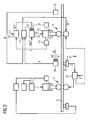
- a cold rolling mill has a plurality of rolling mills 1 to 4, which are passed through in succession by a strip 5 during operation of the cold rolling mill.
- the cold rolling mill has four such rolling stands 1 to 4.
- the number of stands 1 to 4 could alternatively be larger or smaller.
- the cold rolling mill further has a control device 6.
- the control device 6 is connected to the rolling stands 1 to 4 of the cold rolling mill data technically.
- the control device 6 operates the cold rolling mill according to one of the operating methods which will be described below in connection with FIGS FIGS. 2 to 4 be explained in more detail. This is under the FIGS. 2 to 4 In particular, the operation of the last rolling stand 4 and the penultimate rolling stand 3 of the cold rolling mill.
- the remaining rolling stands 1, 2 of the cold rolling mill can be operated in a manner known per se.
- the control device 6 is generally designed as a programmable control device 6, which executes a computer program 7 during operation.
- the computer program 7 in this case comprises machine code 8, which directly from the control device 6 is executable.
- the execution of the machine code 8 causes in this case that the control device 6 operates the cold rolling mill according to an operating method according to the invention.
- the computer program 7 may already have been deposited in the control device 6 during the production of the control device 6. Alternatively, it is possible to supply the computer program 7 to the control device 6 via a computer-computer connection.
- the calculator-computer connection is in FIG. 1 not shown here. It can be designed, for example, as a connection to a LAN or to the Internet. Again alternatively, it is possible to store the computer program 7 on a data carrier 9 in machine-readable form and to supply the computer program 7 to the control device 6 via the data carrier 9.
- the design of the data carrier 9 is hereby arbitrary nature. For example, it is possible that the data carrier 9 is designed as a USB memory stick or as a memory card. Is shown in FIG. 1 an embodiment of the data carrier 9 as a CD-ROM.
- the thickness of the last rolling mill 4 of the cold rolling mill is immediately followed by a thickness measuring device 10.
- a thickness measuring device 10 By means of the thickness measuring device 10, an actual thickness d is detected, which has the band 5 at the location of the thickness measuring device 10.
- the thickness measuring device 10 supplies the actual thickness d detected by it to a thickness control device 11.
- the thickness control device 11 acts on the last stand 4 of the cold rolling mill.
- the thickness control device 11 determines a desired value s * for an adjusting device 12.
- a rolling gap of the last rolling stand 4 of the cold rolling train can be set.
- the determined setpoint value s * is supplied to the thickness control device 11 of a roll gap control device 13 as the setpoint value s *.
- the roll gap control device 13 is further supplied as an actual value s a travel s of the adjusting device 12.
- the roll gap control device 13 determines, based on the quantities s *, s supplied to it, a setting command Q for adjusting the adjusting device 12. It outputs the adjusting command Q to the adjusting device 12.
- the adjusting device 12 is designed as a hydraulic cylinder device. However, this is not mandatory. The only factor is that the adjustment 12 is adjustable under load.
- the thickness control device 11 determines a further manipulated variable ⁇ v *, which acts on the roller speed of the last rolling stand 4 of the cold rolling train.
- a rolling force detecting device 14 is assigned to the last rolling stand 4 of the cold rolling mill.
- an actual rolling force F of the last rolling stand 4 of the cold rolling train is detected and supplied to a force control device 15.
- the rolling force control device 15 determines based on the supplied actual rolling force F and a Sollwalzkraft F * a manipulated variable ⁇ s1 * and outputs this manipulated variable ⁇ s1 * from.
- the manipulated variable ⁇ s1 * output by the force control device 15 is fed to the roll gap control device 13 as an additional setpoint value ⁇ s1 *.
- the roll gap control device 13 is further supplied as a further additional setpoint ⁇ s2 * an eccentricity compensation value ⁇ s2 *.
- This embodiment is preferred, but not mandatory.
- the thickness control device 11 dynamically to the last stand 4 of the cold rolling mill acts. This is in contrast to the prior art, in which although the thickness measuring device 10 is also located behind the last rolling stand 4 of the cold rolling mill, the thickness control device 11, however, acts on the penultimate rolling stand 3 of the cold rolling mill.
- the last rolling mill 4 of the cold rolling mill another thickness gauge 16 is disposed directly upstream.
- a further actual thickness d ' is detected, which has the band 5 at the location of the further thickness measuring device 16.
- the further actual thickness d ' is determined according to FIG. 2 also fed to the thickness control device 11.
- the thickness control device 11 is therefore able to take into account the further actual thickness d 'when determining the setpoint value s *.
- the control variable ⁇ e Q acting on the last roll stand 4 of the cold rolling train is thus varied on the basis of the detected further actual thickness d '.
- the manipulated variable s * which is varied on the basis of the further actual thickness d ', thus acts on the roll gap control device 13.
- a strip tension Z is detected, which prevails between the last rolling stand 4 and the penultimate rolling stand 3 of the cold rolling line in the band 5.
- the strip tension Z and a desired tension Z * are fed to a tension control device 17 which controls the tension Z on the desired tension Z *.
- the tension control device 17 can in this case act in particular on the roller speed of the penultimate rolling stand 3 of the cold rolling train. Alternatively, it is possible as in FIG. 2 indicated by dashed lines that the tension control device 17 acts on the roller speed of the last rolling stand 4 of the cold rolling train.
- the thickness measuring device 10 is arranged downstream of the last rolling stand 4 of the cold rolling mill.
- the thickness measuring device 10 detects the actual thickness d of the strip 5 behind the last roll stand 4 of the cold rolling train and supplies the actual thickness d of the thickness control device 11.
- the thickness control device 11 acts on the last stand 4 of the cold rolling mill.
- the thickness control device 11 the setpoint s * for the adjusting device 12 and leads him to the roll gap control 13 as a setpoint s *.
- the roll gap control device 13 takes the setpoint value s * and the corresponding actual value s and determines in the same way as described above the control command Q for adjusting the adjusting device 12.
- the rolling force detecting device 14 is present, which detects the actual rolling force F of the last rolling stand 4 and the force control device 15 supplies.
- the force control device 15 determines a manipulated variable ⁇ v '* based on the actual rolling force F supplied to it and the nominal rolling force F * also supplied to it and outputs this manipulated variable ⁇ v' *.
- the output from the force control device 15 manipulated variable ⁇ v '* acts on the roller speed of the penultimate roll stand 3 of the cold rolling mill.
- the thickness control device 11 determines a further manipulated variable ⁇ v *, which acts on the roller speed of the last rolling stand 4 of the cold rolling train.
- ⁇ v * a further manipulated variable
- the strip tension Z between the last roll stand 4 and the penultimate roll stand 3 of the cold rolling mill is detected and fed to the tension control device 17.
- the tension control device 17 controls the strip tension Z on the desired train Z *.
- the tension control device 17 acts on the roll gap control device 13.
- FIG. 3 Various advantageous embodiments are possible.
- it is - analogous to FIG. 2 -
- it is possible to feed the roll gap control device 13 as an additional setpoint value ⁇ s2 * the eccentricity compensation value ⁇ s2 *.
- the further actual thickness d 'of the band 5 is detected by means of the further thickness measuring device 16 and fed to the thickness control device 11.
- the thickness control device 11 can vary a manipulated variable s * acting on the last rolling stand 4 of the cold rolling train on the basis of the detected further actual thickness d 'of the belt 5.
- the thickness measuring device 10 the last rolling stand 4 of the cold rolling train immediately downstream. Furthermore, the thickness control device 11 is still present, to which the actual thickness d of the strip 5 is supplied. The thickness control device 11 acts according to the embodiment FIG. 4 continue on the last mill stand 4 of the cold rolling mill.
- the rolling force detecting device 14 is present, which detects the actual rolling force F of the last rolling stand 4 and the force control device 15 supplies.
- the force control device 15 determines (as before) based on their supplied actual rolling force F and a Sollwalzkraft F * a manipulated variable ⁇ s1 * and outputs the manipulated variable ⁇ s1 *.
- the manipulated variable ⁇ s1 * acts - analogous to the embodiment according to FIG. 2 - on the roll gap .regel Singer 13.
- the further actual thickness d 'of the belt 5 is detected by means of the further thickness measuring device 16 immediately preceding the last rolling stand 4 of the cold rolling train and fed to a further thickness control device 11' as the actual value d '.
- the further thickness control device 11 ' in this case acts on the penultimate rolling stand 3 of the cold rolling mill.
- the further thickness control device 11 requires not only the further actual thickness d ', but also a desired thickness d' * for proper regulation.
- the desired thickness d '* is determined by means of a setpoint determination device 18.
- Speed detection devices 19, 20 are provided for this purpose. By means of the speed detection devices 19, 20, speeds v ', v are detected, with which the belt 5 enters the last rolling stand 4 of the cold rolling train and runs out of the last rolling stand 4 of the cold rolling train.
- the detected velocities v ', v and a final thickness d *, which the band 5 should have behind the last mill stand 4 of the cold rolling mill, are fed to the nominal value determination device 18.
- the setpoint determination device 18 determines the desired thickness d '* as a function of the quantities d *, d, v', v supplied to it, and supplies them to the thickness control device 11 as the setpoint value d '*.
- the speeds v, v ' can be determined in various ways.
- the last mill stand 4 according to FIG. 1 an S-roller set 21 is arranged downstream and the peripheral speed of the rollers of the S-roller set 21 is detected.
- This speed v corresponds very well with the outlet side speed of the belt 5 behind the last rolling stand 4.
- other approaches are possible.
- the roll gap control device 13 can be supplied with the additionality setpoint value ⁇ s2 * as additional setpoint value ⁇ s2 *.
- the setpoint determination device 18 can take into account the actual thickness d when determining the setpoint thickness d '*.
- the thickness measuring device 10 by means of which the actual thickness d of the strip 5 is determined behind the last rolling stand 4, is preferably designed as a conventional thickness measuring device.
- the further thickness gauge 16, by means of of which the actual thickness d 'of the strip 5 between the next to last and the last roll stand 3, 4 of the cold rolling train is determined, may be formed in a conventional manner. The following will be in connection with FIG. 5 however, an alternative embodiment of this thickness measuring device 16 is explained.
- the speed v 'of the belt 5 between the penultimate and the last rolling stand 3, 4 of the cold rolling mill is detected.
- the peripheral speed of the tension measuring roller 22 can be detected.
- the peripheral speed of the rollers of the penultimate rolling stand 3 of the cold rolling mill can be detected, and the speed v 'of the belt 5 between the penultimate and last rolling stands 3, 4 of the cold rolling mill can be determined by considering the lead.
- this may alternatively be a point between the penultimate and the third last roll stand 3, 2 or a further from the penultimate roll stand 3 - a speed v0 of the strip 5 and the existing at this point Band thickness d0 detected and the further thickness gauge 16 supplied.
- an input thickness d0 of the strip 5 can be detected on the input side of the cold rolling train by means of an additional thickness measuring device 23.
- an additional thickness measuring device 23 on the input side of the cold rolling mill - for example by detecting the peripheral speed of rollers of an upstream S-roller set 24 - a corresponding input-side belt speed v0 can be detected.
- the respective locations of the belt 4 for which the entrance thicknesses d0 were detected are traced through the cold rolling mill.
- d0 is the initial thickness d0 of the strip 5, with which the point of the strip 5 currently emerging from the penultimate rolling stand 3 was detected by the additional thickness measuring device 23.
- the various control devices 11, 11 ', 13, 15 and 17 and also the setpoint determination device 18 are usually software-implemented. They are therefore parts of the computer program 7.
- the execution of the computer program 7 by the control device 6 therefore causes the control device 6, the corresponding control devices 11, 11 ', 13, 15 and 17 and the setpoint determination device 18 realized.
- the control device 6 controls the detection devices 14, 19, 20 and the control elements 12 (and others).
- the cold rolling mill is operated by the controller 6 in accordance with one of the operation methods explained above.
- the control device 6 is of course also connected to the mentioned devices 10, 12, 14, 16, 19, 20, etc., in terms of data technology.
- the present invention has many advantages.
- the contradiction held in the prior art “constant rolling force control on the last roll stand 4 for the skin pass mill” and “utilization of the setting effect of the setting of the last rolling stand 4 for the damping of thickness defects” is achieved according to the invention. It is both the requirements of a skin pass mill accounted for and the requirements for the dimensional accuracy of the manufactured band 5. Nevertheless, compared to the prior art not previously considered possible dynamics achieved.
Description
Die vorliegende Erfindung betrifft ein Betriebsverfahren für eine mehrgerüstige Kaltwalzstraße zum Walzen eines Bandes,
- wobei mittels einer Walzkrafterfassungseinrichtung eine Istwalzkraft eines letzten Walzgerüsts der Walzstraße erfasst und einer Kraftregeleinrichtung zugeführt wird,
- wobei die Kraftregeleinrichtung anhand der ihr zugeführten Istwalzkraft und einer Sollwalzkraft mindestens eine Stellgröße ermittelt und ausgibt,
- wobei mittels einer dem letzten Walzgerüst der Walzstraße unmittelbar nachgeordneten Dickenmesseinrichtung eine Istdicke des Bandes erfasst und einer Dickenregeleinrichtung zugeführt wird,
- wobei die Dickenregeleinrichtung auf das letzte Walzgerüst der Kaltwalzstraße wirkt.
- wherein, by means of a rolling force detection device, an actual rolling force of a last rolling stand of the rolling train is detected and fed to a force regulating device,
- wherein the force control device determines and outputs at least one manipulated variable on the basis of the actual rolling force supplied thereto and a set rolling force,
- wherein an actual thickness of the strip is detected by means of a last mill stand of the rolling train immediately downstream thickness measuring device and fed to a thickness control device,
- wherein the thickness control device acts on the last stand of the cold rolling mill.
Die vorliegende Erfindung betrifft weiterhin ein Computerprogramm, wobei das Computerprogramm Maschinencode umfasst, der von einer Steuereinrichtung für eine mehrgerüstige Kaltwalzstraße unmittelbar ausführbar ist.The present invention further relates to a computer program, the computer program comprising machine code which is directly executable by a control device for a multi-stand cold rolling mill.
Weiterhin betrifft die vorliegende Erfindung einen Datenträger, auf dem in maschinenlesbarer Form ein Computerprogramm der obenstehend beschriebenen Art gespeichert ist.Furthermore, the present invention relates to a data carrier on which a computer program of the type described above is stored in machine-readable form.
Weiterhin betrifft die vorliegende Erfindung eine Steuereinrichtung für eine mehrgerüstige Kaltwalzstraße, wobei die Steuereinrichtung mit einem derartigen Computerprogramm programmiert ist.Furthermore, the present invention relates to a control device for a multi-stand cold rolling mill, wherein the control device is programmed with such a computer program.
Schließlich betrifft die vorliegende Erfindung eine mehrgerüstige Walzstraße,
- wobei die Kaltwalzstraße mehrere Walzgerüste aufweist, die im Betrieb der Kaltwalzstraße von einem Band nacheinander durchlaufen werden,
- wobei dem letzten Walzgerüst der Kaltwalzstraße eine Walzkrafterfassungseinrichtung zugeordnet ist, mittels derer eine Istwalzkraft des letzten Walzgerüsts erfassbar ist,
- wobei dem letzten Walzgerüst der Kaltwalzstraße eine Dickenmesseinrichtung, mittels derer eine Istdicke des Bandes erfassbar ist, unmittelbar nachgeordnet ist,
- wobei die Kaltwalzstraße eine Steuereinrichtung der obenstehend beschriebenen Art aufweiset, die mit den Walzgerüsten der Kaltwalzstraße, der Walzkrafterfassungseinrichtung und der Dickenmesseinrichtung datentechnisch verbunden ist.
- wherein the cold rolling mill has a plurality of rolling mills, which are passed through in succession by a strip during operation of the cold rolling mill,
- wherein the last rolling stand of the cold rolling train is assigned a rolling force detecting device by means of which an actual rolling force of the last rolling stand can be detected,
- wherein the last rolling stand of the cold rolling train is a thickness measuring device, by means of which an actual thickness of the belt is detected, immediately downstream,
- wherein the cold rolling line comprises a control device of the type described above, which is connected to the rolling stands of the cold rolling mill, the rolling force detecting device and the thickness measuring device in terms of data technology.
Die obenstehend beschriebenen Gegenstände sind allgemein bekannt. Rein beispielhaft wird auf die
Bei mehrgerüstigen Kaltwalzwerken wird üblicherweise die Banddicke hinter dem ersten und hinter dem letzten Walzgerüst der Kaltwalzstraße gemessen. Banddickenfehler, die in den dazwischen liegenden Walzgerüsten der Kaltwalzstraße auftreten, werden erst durch die Dickenmessung hinter dem letzten Walzgerüst der Kaltwalzstraße bemerkt. Die totzeitbehaftete auslaufseitige Monitorregelung der Kaltwalzstraße kann diese Fehler prinzipbedingt nur unvollständig ausregeln. Insbesondere im sogenannten Modus C, in dem das letzte Walzgerüst der Kaltwalzstraße als Dressiergerüst mit konstanter Walzkraft betrieben wird, gestaltet sich die Ausregelung der Dickenfehler als schwierig. Der Grund besteht hierbei darin, dass die Monitorregelung auf das letzte walzspaltgeregelte Walzgerüst wirkt, d. h. auf das vorletzte Walzgerüst der Kaltwalzstraße. Die Totzeit besteht somit aus der Transportzeit, die das Band vom vorletzten Walzgerüst der Walzstraße bis zur Dickenmesseinrichtung benötigt. Dadurch ist nur eine sehr geringe Reglerdynamik erreichbar.In multi-stand cold rolling mills, the strip thickness is usually measured behind the first and behind the last mill stand of the cold rolling mill. Tape thickness errors that occur in the intervening stands of the cold rolling mill are not noticed until after the thickness measurement behind the last mill stand of the cold rolling mill. The deadtime-dependent outlet-side monitor control of the cold rolling mill can only partially compensate for these errors. In particular, in the so-called mode C, in which the last rolling stand of the cold rolling mill is operated as a skin pass mill with constant rolling force, the compensation of the thickness errors designed as difficult. The reason for this is that the monitor control system acts on the last roll-gap-controlled rolling stand, ie on the penultimate roll stand of the cold rolling mill. The dead time thus consists of the transport time, which requires the band from the penultimate roll stand of the rolling mill to the thickness gauge. As a result, only a very small control dynamics can be achieved.
Wie bereits erwähnt, wird im Dressiermodus C das letzte Walzgerüst der mehrgerüstigen Kaltwalzstraße mit konstanter Walzkraft betrieben. Zu diesem Zweck ist die Anstellung des letzten Walzgerüsts kraftgeregelt. Auf Grund der Walzkraftregelung reagiert das letzte Walzgerüst auf Dickenfehler des Bandes dadurch, dass es entsprechend nachgibt. Die Banddickenfehler durchlaufen das letzte Walzgerüst der Kaltwalzstraße somit ungedämpft. Die auslaufseitige Monitorregelung, d. h. die Dickenmesseinrichtung hinter der Kaltwalzstraße, verändert bei Bedarf die Stichabnahme des vorletzten Walzgerüsts der Kaltwalzstraße. Auf Grund der großen Totzeit zwischen dem Stelleingriff am vorletzten Walzgerüst der Kaltwalzstraße und der nachfolgenden Messung mittels der Dickenmesseinrichtung können jedoch nur niederfrequente Störungen ausreichend ausgeregelt werden.As already mentioned, in rolling-through mode C, the last stand of the multi-stand cold rolling mill is operated with a constant rolling force. For this purpose, the employment of the last rolling stand is force-controlled. Due to the rolling force control, the last roll stand responds to thickness errors of the strip by giving way accordingly. The band thickness errors run through the last mill stand of the cold rolling line thus undamped. The outlet side monitor control, d. H. If necessary, the thickness gauge downstream of the cold rolling mill changes the stock removal of the penultimate roll stand of the cold rolling mill. Due to the large dead time between the control intervention on the penultimate rolling stand of the cold rolling mill and the subsequent measurement by means of the thickness gauge, however, only low-frequency disturbances can be adequately compensated.
Die Aufgabe der vorliegenden Erfindung besteht darin, Möglichkeiten zu schaffen, mittels derer Dickenfehler im gewalzten Band mit höherer Dynamik ausregelbar sind.The object of the present invention is to provide opportunities by means of which thickness errors in the rolled strip can be adjusted with higher dynamics.
Die Aufgabe wird verfahrenstechnisch durch ein Betriebsverfahren mit den Merkmalen des Anspruchs 1 gelöst. Vorteilhafte Ausgestaltungen des Betriebsverfahrens sind Gegenstand der abhängigen Ansprüche 2 bis 15.The object is procedurally achieved by an operating method with the features of claim 1. Advantageous embodiments of the operating method are the subject of the dependent claims 2 to 15.
Erfindungsgemäß ist bei einem Betriebsverfahren der obenstehend beschriebenen Art vorgesehen,
- dass mittels einer dem letzten Walzgerüst der Kaltwalzstra-βe unmittelbar vorgeordneten weiteren Dickenmesseinrichtung eine weitere Istdicke des Bandes erfasst wird,
- dass mittels Geschwindigkeitserfassungseinrichtungen Geschwindigkeiten erfasst werden, mit denen das Band in das letzte Walzgerüst der Kaltwalzstraße einläuft und aus dem letzten Walzgerüst der Kaltwalzstraße ausläuft,
- dass die erfassten Geschwindigkeiten und eine vorbestimmte Enddicke, die das Band hinter dem letzten Walzgerüst der Kaltwalzstraße aufweisen soll, einer Sollwertermittlungseinrichtung zugeführt werden,
- dass die Sollwertermittlungseinrichtung in Abhängigkeit von den ihr zugeführten Größen eine Solldicke ermittelt und
- dass einer auf das vorletzte Walzgerüst der Kaltwalzstraße wirkenden weiteren Dickenregeleinrichtung die Solldicke als Sollwert und die weitere Istdicke als Istwert zugeführt werden.
- that a further actual thickness of the strip is detected by means of a further thickness measuring device directly preceding the last rolling stand of the cold rolling train βe,
- in that speeds are detected by means of speed detection devices with which the strip enters the last mill stand of the cold rolling mill and runs out of the last mill stand of the cold rolling mill,
- that the detected speeds and a predetermined final thickness, which the strip is to have behind the last mill stand of the cold rolling mill, are fed to a nominal value determination device,
- the setpoint determination device determines a setpoint thickness as a function of the quantities supplied to it and
- in that a further thickness control device acting on the penultimate roll stand of the cold rolling train is supplied with the setpoint thickness as desired value and the further actual thickness as actual value.
Eine vorteilhafte Ausgestaltung der vorliegenden Erfindung besteht darin,
- dass die Dickenregeleinrichtung einen Sollwert für eine Verstelleinrichtung für den Walzspalt des letzten Walzgerüsts der Kaltwalzstraße ermittelt und einer Walzspaltregeleinrichtung als Sollwert zuführt,
- dass der Walzspaltregeleinrichtung weiterhin als Istwert ein Stellweg der Verstelleinrichtung zugeführt wird,
- dass die Walzspaltregeleinrichtung anhand der ihr zugeführten Größen einen Stellbefehl zum Verstellen der Verstelleinrichtung ermittelt und an die Verstelleinrichtung ausgibt und
- dass die Dickenregeleinrichtung eine Stellgröße für die Walzengeschwindigkeit des letzten Walzgerüsts der Kaltwalzstraße ermittelt und an das letzte Walzgerüst der Kaltwalzstraße ausgibt.
- the thickness control device determines a setpoint value for an adjustment device for the roll gap of the last roll stand of the cold rolling train and feeds it to a roll gap control device as the setpoint,
- that the roll gap control device is further supplied as an actual value a travel of the adjusting device,
- that the roll gap control device determines, based on the quantities supplied to it, a positioning command for adjusting the adjusting device and outputs it to the adjusting device and
- that the thickness control device determines a manipulated variable for the roller speed of the last roll stand of the cold rolling mill and outputs it to the last roll stand of the cold rolling mill.
Vorzugsweise wird der Walzspaltregeleinrichtung als Zusatzsollwert weiterhin ein Exzentrizitätskompensationswert zugeführt. Durch diese Maßnahme können exzentrizitätsbedingte Banddickenfehler kompensiert werden.Preferably, the roll gap control device is additionally supplied with an eccentricity compensation value as an additional setpoint. By this measure, eccentricity-related band thickness errors can be compensated.
Vorzugsweise ist weiterhin vorgesehen, dass die von der Kraftregeleinrichtung ausgegebene Stellgröße der Walzspaltregeleinrichtung als zusätzlicher Sollwert zugeführt wird. Durch diese Ausgestaltung ist die Kraftregeleinrichtung der Walzspaltregeleinrichtung überlagert, so dass im Ergebnis das letzte Walzgerüst der Kaltwalzstraße direkt kraftgeregelt betrieben wird.Preferably, it is further provided that the output from the force control device manipulated variable of the roll gap control device is supplied as an additional setpoint. By this embodiment, the force control device of the roll gap control device is superimposed, so that as a result the last rolling stand of the cold rolling train is operated directly controlled by force.
Alternativ ist es möglich,
- dass die von der Kraftregeleinrichtung ausgegebene Stellgröße auf die Walzengeschwindigkeit des vorletzten Walzgerüsts der Kaltwalzstraße wirkt,
- dass ein im Band zwischen dem letzten Walzgerüst und dem vorletzten Walzgerüst der Kaltwalzstraße herrschender Bandzug erfasst und mittels einer Zugregeleinrichtung auf einen Sollzug geregelt wird und
- dass die Zugregeleinrichtung auf die Walzspaltregeleinrichtung wirkt.
- that the manipulated variable output by the force control device acts on the roller speed of the penultimate rolling mill stand of the cold rolling mill,
- that a strip tension prevailing in the strip between the last roll stand and the penultimate roll stand of the cold rolling mill is detected and regulated by means of a tension control device to a desired tension, and
- that the tension control device acts on the roll gap control device.
In diesem Fall ergibt sich eine indirekte Kraftregelung des letzten Walzgerüsts der Kaltwalzstraße.In this case, there is an indirect force control of the last mill stand of the cold rolling mill.
In einer bevorzugten Ausgestaltung der vorliegenden Erfindung ist weiterhin vorgesehen,
- dass der Sollwertermittlungseinrichtung auch die Istdicke zugeführt wird und
- dass die Sollwertermittlungseinrichtung die Istdicke bei der Ermittlung der Solldicke berücksichtigt.
- the setpoint determination device is also supplied with the actual thickness and
- the setpoint determination device takes into account the actual thickness in the determination of the setpoint thickness.
Durch diese Ausgestaltung werden noch bessere Regelergebnisse erzielt.This refinement results in even better control results.
Es ist möglich, die weitere Dickenmesseinrichtung auf konventionelle Art und Weise auszugestalten. Alternativ ist es möglich, dass die weitere Dickenmesseinrichtung die weitere Istdicke des Bandes indirekt anhand einer vor dem vorletzten Walzgerüst der Kaltwalzstraße erfassten Geschwindigkeit des Bandes, einer bekannten korrespondierenden Istdicke des Bandes und einer erfassten Geschwindigkeit des Bandes zwischen dem vorletzten und dem letzten Walzgerüst der Kaltwalzstraße ermittelt.It is possible to design the further thickness measuring device in a conventional manner. Alternatively, it is possible for the further thickness measuring device to determine the further actual thickness of the strip indirectly on the basis of a speed of the strip detected before the penultimate roll stand of the cold rolling train, a known corresponding actual thickness of the strip and a detected speed of the strip between the penultimate and last rolling stands of the cold rolling line ,
Die Aufgabe wird weiterhin programmtechnisch durch ein Computerprogramm mit den Merkmalen des Anspruchs 10 gelöst. In diesem Fall umfasst das Computerprogramm Maschinencode, der von einer Steuereinrichtung für eine mehrgerüstige Kaltwalzstraße unmittelbar ausführbar ist. Die Ausführung des Maschinencodes durch die Steuereinrichtung bewirkt, dass die Steuereinrichtung die obenstehend erwähnten Regeleinrichtungen realisiert, die obenstehend erwähnten Erfassungs- und Messeinrichtungen ansteuert und die obenstehend erwähnten Stellelemente ansteuert. Im Ergebnis wird dadurch erreicht, dass die Kaltwalzstraße von der Steuereinrichtung gemäß einem Betriebsverfahren der obenstehend beschriebenen Art betrieben wird.The task is further solved programmatically by a computer program having the features of
Die Aufgabe wird weiterhin durch einen Datenträger gelöst, auf dem in maschinenlesbarer Form ein Computerprogramm der zuletzt beschriebenen Art gespeichert ist.The object is further achieved by a data carrier on which a computer program of the type described last is stored in machine-readable form.
Einrichtungstechnisch wird die Aufgabe durch eine Steuereinrichtung für eine mehrgerüstige Kaltwalzstraße gelöst, wobei die Steuereinrichtung mit einem Computerprogramm der obenstehend beschriebenen Art programmiert ist. Dadurch ist die Steuereinrichtung in der Lage, die entsprechenden Regeleinrichtungen zu realisieren, die entsprechenden Erfassungs- und Messeinrichtungen anzusteuern und die entsprechenden Stellelemente anzusteuern, so dass im Ergebnis die Kaltwalzstraße von der Steuereinrichtung gemäß einem Betriebsverfahren der obenstehend beschriebenen Art betrieben wird.In terms of equipment, the object is achieved by a control device for a multi-stand cold rolling mill, wherein the control device is programmed with a computer program of the type described above. As a result, the control device is able to implement the corresponding control devices, to control the corresponding detection and measuring devices and to control the corresponding control elements, so that as a result the cold rolling train is operated by the control device according to an operating method of the type described above.
Anlagentechnisch wird die Aufgabe durch eine mehrgerüstige Kaltwalzstraße mit den Merkmalen des Anspruchs 13 gelöst. Die mehrgerüstige Kaltwalzstraße weist mehrere Walzgerüste auf, die im Betrieb der Kaltwalzstraße von einem Band nacheinander durchlaufen werden. Dem letzten Walzgerüst der Kaltwalzstraße ist eine Walzkrafterfassungseinrichtung zugeordnet, mittels derer eine Istwalzkraft des letzten Walzgerüsts erfassbar ist. Dem letzten Walzgerüst der Kaltwalzstraße ist eine Dickenmesseinrichtung, mittels derer eine Istdicke des Bandes erfassbar ist, unmittelbar nachgeordnet. Die Kaltwalzstraße weist eine Steuereinrichtung der obenstehend beschriebenen Art auf, die mit den Walzgerüsten der Kaltwalzstraße, der Walzkrafterfassungseinrichtung und der Dickenmesseinrichtung datentechnisch verbunden ist, so dass die Kaltwalzstraße von der Steuereinrichtung gemäß einem Betriebsverfahren der obenstehend beschriebenen Art betrieben werden.Plant technology, the problem is solved by a multi-stand cold rolling mill with the features of
Weitere Vorteile und Einzelheiten ergeben sich aus der nachfolgenden Beschreibung von Ausführungsbeispielen in Verbindung mit den Zeichnungen. Es zeigen in Prinzipdarstellung:
- FIG 1
- eine mehrgerüstige Kaltwalzstraße,
- FIG 2 bis 4
- mögliche Ausgestaltungen eines Ausschnitts der Kaltwalzstraße von
FIG 1 und - FIG 5
- eine mögliche Ausgestaltung einer Dickenmesseinrichtung.
- FIG. 1
- a multi-stand cold rolling mill,
- FIGS. 2 to 4
- possible embodiments of a section of the cold rolling mill of
FIG. 1 and - FIG. 5
- a possible embodiment of a thickness measuring device.
Gemäß
Die Kaltwalzstraße weist weiterhin eine Steuereinrichtung 6 auf. Die Steuereinrichtung 6 ist mit den Walzgerüsten 1 bis 4 der Kaltwalzstraße datentechnisch verbunden. Die Steuereinrichtung 6 betreibt die Kaltwalzstraße gemäß einem der Betriebsverfahren, die nachfolgend in Verbindung mit den
Die Steuereinrichtung 6 ist in der Regel als programmierbare Steuereinrichtung 6 ausgebildet, die im Betrieb ein Computerprogramm 7 ausführt. Das Computerprogramm 7 umfasst hierbei Maschinencode 8, der von der Steuereinrichtung 6 unmittelbar ausführbar ist. Die Ausführung des Maschinencodes 8 bewirkt in diesem Fall, dass die Steuereinrichtung 6 die Kaltwalzstraße entsprechend einem erfindungsgemäßen Betriebsverfahren betreibt.The control device 6 is generally designed as a programmable control device 6, which executes a
Das Computerprogramm 7 kann bereits bei der Herstellung der Steuereinrichtung 6 in der Steuereinrichtung 6 hinterlegt worden sein. Alternativ ist es möglich, das Computerprogramm 7 der Steuereinrichtung 6 über eine Rechner-Rechner-Verbindung zuzuführen. Die Rechner-Rechner-Verbindung ist in
Gemäß
Insbesondere ermittelt die Dickenregeleinrichtung 11 einen Sollwert s* für eine Verstelleinrichtung 12. Mittels der Verstelleinrichtung 12 ist ein Walzspalt des letzten Walzgerüsts 4 der Kaltwalzstraße einstellbar. Den ermittelten Sollwert s* führt die Dickenregeleinrichtung 11 einer Walzspaltregeleinrichtung 13 als Sollwert s* zu.In particular, the
Der Walzspaltregeleinrichtung 13 wird weiterhin als Istwert s ein Stellweg s der Verstelleinrichtung 12 zugeführt. Die Walzspaltregeleinrichtung 13 ermittelt anhand der ihr zugeführten Größen s*, s einen Stellbefehl Q zum Verstellen der Verstelleinrichtung 12. Sie gibt den Verstellbefehl Q an die Verstelleinrichtung 12 aus.The roll
Gemäß
Weiterhin ermittelt die Dickenregeleinrichtung 11 eine weitere Stellgröße δv*, welche auf die Walzengeschwindigkeit des letzten Walzgerüsts 4 der Kaltwalzstraße wirkt.Furthermore, the
Gemäß
Gemäß
Auf Grund der obenstehend in Verbindung mit
Die obenstehend in Verbindung mit
Gemäß
Alternativ zu der Ausgestaltung gemäß
Auch bei der Ausgestaltung gemäß
Weiterhin ermittelt auch bei der Ausgestaltung gemäß
Weiterhin ist auch bei der Ausgestaltung gemäß
Durch die Ausgestaltung gemäß
Auch bei der Ausgestaltung gemäß
Weiterhin ist es möglich, dass mittels der weiteren Dickenmesseinrichtung 16 die weitere Istdicke d' des Bandes 5 erfasst und der Dickenregeleinrichtung 11 zugeführt wird. Auch in diesem Fall kann die Dickenregeleinrichtung 11 anhand der erfassten weiteren Istdicke d' des Bandes 5 eine auf das letzte Walzgerüst 4 der Kaltwalzstraße wirkende Stellgröße s* variieren.Furthermore, it is possible that the further actual thickness d 'of the
Weiterhin ist es möglich, die Kaltwalzstraße gemäß einem Betriebsverfahren zu betreiben, das nachfolgend in Verbindung mit
Auch bei der Ausgestaltung gemäß
Bei der Ausgestaltung gemäß
Weiterhin wird bei der Ausgestaltung gemäß
Die weitere Dickenregeleinrichtung 11 benötigt zum ordnungsgemäßen Regeln nicht nur die weitere Istdicke d', sondern auch eine Solldicke d'*. Die Solldicke d'* wird mittels einer Sollwertermittlungseinrichtung 18 ermittelt. Zu diesem Zweck sind Geschwindigkeitserfassungseinrichtungen 19, 20 vorhanden. Mittels der Geschwindigkeitserfassungseinrichtungen 19, 20 werden Geschwindigkeiten v', v erfasst, mit denen das Band 5 in das letzte Walzgerüst 4 der Kaltwalzstraße einläuft und aus dem letzten Walzgerüst 4 der Kaltwalzstraße ausläuft. Die erfassten Geschwindigkeiten v', v und eine Enddicke d*, die das Band 5 hinter den letzten Walzgerüst 4 der Kaltwalzstraße aufweisen soll, werden der Sollwertermittlungseinrichtung 18 zugeführt. Die Sollwertermittlungseinrichtung 18 ermittelt in Abhängigkeit von den ihr zugeführten Größen d*, d, v', v die Solldicke d'* und führt sie der Dickenregeleinrichtung 11 als Sollwert d'* zu.The further
Die Formel zum Ermitteln der Solldicke d* ergibt sich anhand der Kontinuitätsgleichung. Denn es soll gelten ![]()
![]()
Die Geschwindigkeiten v, v' können auf verschiedene Arten ermittelt werden. Beispielsweise ist es möglich, dass dem letzten Walzgerüst 4 gemäß
Auch bei der Ausgestaltung gemäß
Auch bei der Ausgestaltung gemäß
Als weitere Ausgestaltung des Betriebsverfahrens gemäß
Die Dickenmesseinrichtung 10, mittels derer die Istdicke d des Bandes 5 hinter dem letzten Walzgerüst 4 ermittelt wird, ist vorzugsweise als konventionelle Dickenmesseinrichtung ausgebildet. Auch die weitere Dickenmesseinrichtung 16, mittels derer die Istdicke d' des Bandes 5 zwischen dem vorletzten und dem letzten Walzgerüst 3, 4 der Kaltwalzstraße ermittelt wird, kann auf konventionelle Weise ausgebildet sein. Nachfolgend wird in Verbindung mit
Gemäß
Weiterhin wird an einer dem vorletzten Walzgerüst 3 vorgeordneten Stelle - dies kann alternativ eine Stelle zwischen dem vorletzten und dem drittletzten Walzgerüst 3, 2 oder eine noch weiter vom vorletzten Walzgerüst 3 entfernte Stelle sein - eine Geschwindigkeit v0 des Bandes 5 und die an dieser Stelle vorhandene Banddicke d0 erfasst und der weiteren Dickenmesseinrichtung 16 zugeführt. Beispielsweise kann mittels einer zusätzlichen Dickenmesseinrichtung 23 eingangsseitig der Kaltwalzstraße eine Eingangsdicke d0 des Bandes 5 erfasst werden. In analoger Weise kann eingangsseitig der Kaltwalzstraße - beispielsweise durch Erfassung der Umfangsgeschwindigkeit von Rollen eines vorgeordneten S-Rollensatzes 24 - eine korrespondierende eingangsseitige Bandgeschwindigkeit v0 erfasst werden.Furthermore, at a position upstream of the penultimate rolling stand 3 - this may alternatively be a point between the penultimate and the third
Die jeweiligen Stellen des Bandes 4, für welche die Eingangsdicken d0 erfasst wurden, werden durch die Kaltwalzstraße hindurch wegverfolgt. Zum korrekten Zeitpunkt wird mittels der weiteren Dickenmesseinrichtung 16 die weitere Istdicke d' ermittelt. Die Ermittlung erfolgt hierbei anhand der Beziehung ![]()
v0 und v' sind hierbei die aktuell erfassten Geschwindigkeiten. d0 ist die Anfangsdicke d0 des Bandes 5, mit der die momentan aus dem vorletzten Walzgerüst 3 auslaufende Stelle des Bandes 5 von der zusätzlichen Dickenmesseinrichtung 23 erfasst wurde.The respective locations of the belt 4 for which the entrance thicknesses d0 were detected are traced through the cold rolling mill. At the correct time, the further actual thickness d 'is determined by means of the further ![]()
v0 and v 'are the currently recorded speeds. d0 is the initial thickness d0 of the
Die verschiedenen Regeleinrichtungen 11, 11', 13, 15 und 17 und auch die Sollwertermittlungseinrichtung 18 sind in der Regel softwarerealisiert. Sie sind also Teile des Computerprogramms 7. Die Ausführung des Computerprogramms 7 durch die Steuereinrichtung 6 bewirkt daher, dass die Steuereinrichtung 6 die entsprechenden Regeleinrichtungen 11, 11', 13, 15 und 17 sowie die Sollwertermittlungseinrichtung 18 realisiert. Weiterhin steuert die Steuereinrichtung 6 auf Grund der Ausführung des Maschinencodes 8 die Erfassungseinrichtungen 14, 19, 20 und die Stellelemente 12 (und andere) an. Im Ergebnis wird daher die Kaltwalzstraße von der Steuereinrichtung 6 gemäß einem der obenstehend erläuterten Betriebsverfahren betrieben. Weiterhin ist die Steuereinrichtung 6 selbstverständlich auch mit den genannten Einrichtungen 10, 12, 14, 16, 19, 20 usw. datentechnisch verbunden.The
Die vorliegende Erfindung weist viele Vorteile auf. Insbesondere wird der im Stand der Technik für unauflösbar gehaltene Widerspruch "konstante Walzkraftregelung am letzten Walzgerüst 4 für den Dressierbetrieb" und "Nutzung der Stellwirkung der Anstellung des letzten Walzgerüsts 4 für die Bedämpfung von Dickenfehlern" erfindungsgemäß gelöst. Es wird sowohl den Anforderungen an einen Dressierbetrieb Rechnung getragen als auch den Anforderungen an die Maßhaltigkeit des gefertigten Bandes 5. Dennoch wird eine gegenüber dem Stand der Technik bisher nicht für möglich gehaltene Dynamik erreicht.The present invention has many advantages. In particular, the contradiction held in the prior art "constant rolling force control on the last roll stand 4 for the skin pass mill" and "utilization of the setting effect of the setting of the last rolling stand 4 for the damping of thickness defects" is achieved according to the invention. It is both the requirements of a skin pass mill accounted for and the requirements for the dimensional accuracy of the manufactured
Die obige Beschreibung dient ausschließlich der Erläuterung der vorliegenden Erfindung. Der Schutzumfang der vorliegenden Erfindung soll hingegen ausschließlich durch die beigefügten Ansprüche bestimmt sein.The above description is only for explanation of the present invention. The scope of protection of the present On the other hand, the invention should be determined solely by the appended claims.
Claims (13)
- Operating method for a multi-stand cold-rolling mill train for rolling a strip (5),- wherein an actual rolling force (F) of a last rolling stand (4) of the cold-rolling mill train is detected and fed to a force controlling device (15) by means of a rolling force detection device (14),- wherein the force controlling device (15) determines at least one manipulated variable (δs1*, δv'*) on the basis of the actual rolling force (F) fed thereto and a desired rolling force (F*), and outputs said variable,- wherein an actual thickness (d) of the strip (5) is detected and fed to a thickness controlling device (11) by means of a thickness measuring device (10) arranged immediately downstream from the last rolling stand (4) of the cold-rolling mill train,- wherein the thickness controlling device (11) acts on the last rolling stand (4) of the cold-rolling mill train,characterized- in that a further actual thickness (d') of the strip (5) is detected by means of a further thickness measuring device (16) arranged immediately upstream from the last rolling stand (4) of the cold-rolling mill train,- in that speed detection devices (19, 20) are used to detect speeds (v', v) at which the strip (5) runs into the last rolling stand (4) of the cold-rolling mill train and runs out of the last rolling stand (4) of the cold-rolling mill train,- in that the detected speeds (v', v) and a predetermined final thickness (d*), which the strip (5) should have downstream from the last rolling stand (4) of the cold-rolling mill train, are fed to a setpoint value determination device (18),- in that the setpoint value determination device (18) determines a desired thickness (d'*) as a function of the variables (v', v, d*, d) fed thereto, and- in that a further thickness controlling device (11') acting on the penultimate rolling stand (3) of the cold-rolling mill train is fed the desired thickness (d'*) as a setpoint value (d'*) and the further actual thickness (d') as an actual value (d').
- Operating method according to Claim 1,
characterized- in that the thickness controlling device (11) determines a setpoint value (s*) for an adjustment device (12) for the roll nip of the last rolling stand (4) of the cold-rolling mill train and feeds it as a setpoint value (s*) to a roll nip controlling device (13),- in that an adjustment distance (s) of the adjustment device (12) is also fed as an actual value (s) to the roll nip controlling device (13),- in that the roll nip controlling device (13) determines an adjustment command (Q) for adjusting the adjustment device (12) on the basis of the variables (s, s*, δs1*, δs2*) fed thereto, and outputs said command to the adjustment device (12), and- in that the thickness controlling device (11) determines a manipulated variable (δv*) for the rolling speed of the last rolling stand (4) of the cold-rolling mill train and outputs it to the last rolling stand (4) of the cold-rolling mill train. - Operating method according to Claim 2,
characterized in that an eccentricity compensation value (δs2*) is also fed as an additional setpoint value (δs2*) to the roll nip controlling device (13). - Operating method according to Claim 2 or 3,
characterized in that the manipulated variable (δs1*) output by the force controlling device (15) is fed as an additional setpoint value (δs1*) to the roll nip controlling device (13). - Operating method according to Claim 4,
characterized in that a strip tension (Z) prevailing in the strip (5) between the last rolling stand (4) and the penultimate rolling stand (3) of the cold-rolling mill train is detected and controlled to a desired tension (Z*) by means of a tension controlling device (17). - Operating method according to Claim 5,
characterized in that the tension controlling device (17) acts on the rolling speed of the last rolling stand (4) or of the penultimate rolling stand (3) of the cold-rolling mill train or on the roll nip controlling device (13). - Operating method according to Claim 2 or 3,
characterized- in that the manipulated variable (δv'*) output by the force controlling device (15) acts on the rolling speed of the penultimate rolling stand (3) of the cold-rolling mill train,- in that a strip tension (Z) prevailing in the strip (5) between the last rolling stand (4) and the penultimate rolling stand (3) of the cold-rolling mill train is detected and controlled to a desired tension (Z*) by means of a tension controlling device (17), and- in that the tension controlling device (17) acts on the roll nip controlling device (13). - Operating method according to one of the above claims, characterized- in that the actual thickness (d) is also fed to the setpoint value determination device (18), and- in that the setpoint value determination device (18) takes the actual thickness (d) into account when determining the desired thickness (d'*).
- Operating method according to one of the above claims, characterized in that the further thickness measuring device (16) determines the further actual thickness (d') of the strip (5) indirectly on the basis of a speed (v0) of the strip (5) detected upstream from the penultimate rolling stand (3) of the cold-rolling mill train, a known corresponding actual thickness (d0) of the strip (5) and a detected speed (v') of the strip (5) between the penultimate rolling stand (3) and the last rolling stand (4) of the cold-rolling mill train.
- Computer program, the computer program comprising machine code (8) which can be executed directly by a control device (6) for a multi-stand cold-rolling mill train, the execution of the machine code (8) by the control device (6) having the effect that the control device (6) realizes the controlling devices (11, 11', 13, 15, 17) mentioned in one of the above claims, controls the detection and measuring devices (10, 14, 16, 19, 20) mentioned in one of the above claims and controls the adjustment elements (12) mentioned in one of the above claims, and as a result the control device (6) operates the cold-rolling mill train in accordance with an operating method according to one of the above claims.
- Data storage medium, on which a computer program (7) according to Claim 10 is stored in machine-readable form.
- Control device for a multi-stand cold-rolling mill train, wherein the control device is programmed with a computer program (7) according to Claim 10 such that it is able to realize the controlling devices (11, 11', 13, 15, 17) mentioned in one of Claims 1 to 9, control the detection and measuring devices (10, 14, 16, 19, 20) mentioned in one of Claims 1 to 9 and control the adjustment elements (12) mentioned in one of Claims 1 to 9, and as a result the control device operates the cold-rolling mill train in accordance with an operating method according to one of Claims 1 to 9.
- Multi-stand cold-rolling mill train,- wherein the cold-rolling mill train has a plurality of rolling stands (1 to 4) through which a strip (5) passes in succession during operation of the cold-rolling mill train,- wherein a rolling force detection device (14) is assigned to the last rolling stand (4) of the cold-rolling mill train and can be used to detect an actual rolling force (F) of the last rolling stand (4),- wherein a thickness measuring device (10), which can be used to detect an actual thickness (d) of the strip (5), is arranged immediately downstream from the last rolling stand (4) of the cold-rolling mill train, and- wherein the cold-rolling mill train has a control device (6) according to Claim 12, and this control device is connected to the rolling stands (1 to 4) of the cold-rolling mill train, to the rolling force detection device (14) and to the thickness measuring device (10) by a data link, such that the control device (6) operates the cold-rolling mill train in accordance with an operating method according to one of Claims 1 to 9.
Priority Applications (1)
| Application Number | Priority Date | Filing Date | Title |
|---|---|---|---|
| PL09718646T PL2268427T3 (en) | 2008-03-14 | 2009-03-09 | Operating method for a cold-rolling line with improved dynamics |
Applications Claiming Priority (2)
| Application Number | Priority Date | Filing Date | Title |
|---|---|---|---|
| DE102008014304A DE102008014304A1 (en) | 2008-03-14 | 2008-03-14 | Operating procedure for a cold rolling mill with improved dynamics |
| PCT/EP2009/052697 WO2009112443A1 (en) | 2008-03-14 | 2009-03-09 | Operating method for a cold-rolling line with improved dynamics |
Publications (2)
| Publication Number | Publication Date |
|---|---|
| EP2268427A1 EP2268427A1 (en) | 2011-01-05 |
| EP2268427B1 true EP2268427B1 (en) | 2013-01-30 |
Family
ID=40670971
Family Applications (1)
| Application Number | Title | Priority Date | Filing Date |
|---|---|---|---|
| EP09718646A Active EP2268427B1 (en) | 2008-03-14 | 2009-03-09 | Operating method for a cold-rolling line with improved dynamics |
Country Status (8)
| Country | Link |
|---|---|
| US (1) | US8516869B2 (en) |
| EP (1) | EP2268427B1 (en) |
| CN (1) | CN101970140B (en) |
| BR (1) | BRPI0909292A2 (en) |
| DE (1) | DE102008014304A1 (en) |
| PL (1) | PL2268427T3 (en) |
| RU (1) | RU2500494C2 (en) |
| WO (1) | WO2009112443A1 (en) |
Families Citing this family (4)
| Publication number | Priority date | Publication date | Assignee | Title |
|---|---|---|---|---|
| DE102006008574A1 (en) * | 2006-02-22 | 2007-08-30 | Siemens Ag | Reducing the influence of roller excentricity on the thickness of a rolled material, comprises identifying the roller excentricity and determining a correction signal for a control unit |
| DE102008014304A1 (en) | 2008-03-14 | 2009-09-24 | Siemens Aktiengesellschaft | Operating procedure for a cold rolling mill with improved dynamics |
| CN104338754B (en) * | 2014-10-22 | 2016-04-13 | 山东钢铁股份有限公司 | A kind of reversing cold mill operating desk authority control method |
| JP7375947B2 (en) * | 2020-09-04 | 2023-11-08 | 東芝三菱電機産業システム株式会社 | Tandem cold rolling mill control system |
Family Cites Families (18)
| Publication number | Priority date | Publication date | Assignee | Title |
|---|---|---|---|---|
| CA932432A (en) | 1968-02-02 | 1973-08-21 | Andrew W. Smith, Jr. | Predictive gauge control method and apparatus with automatic plasticity determination for metal rolling mills |
| US3983194A (en) * | 1971-07-13 | 1976-09-28 | Oxy Metal Industries Corporation | Process for manufacturing a helical reverse osmosis segment |
| SU980891A1 (en) * | 1981-05-11 | 1982-12-15 | Всесоюзный Научно-Исследовательский Институт Автоматизации Черной Металлургии Научно-Производственное Объединение "Черметавтоматика" | System for simultaneous control of strip thickness and profile in continuous rolling mill stand |
| DE3274956D1 (en) * | 1981-09-30 | 1987-02-12 | Mitsubishi Electric Corp | Control device for a continuous rolling machine |
| SU1202650A1 (en) | 1983-07-08 | 1986-01-07 | Научно-Исследовательский Институт Тяжелого Машиностроения Производственного Объединения "Уралмаш" | Apparatus for automatic control of strip thickness of continuous rolling mill |
| ATE46464T1 (en) * | 1983-09-08 | 1989-10-15 | Lysaght Australia Ltd | STRIP THICKNESS CONTROLLER FOR A ROLLING MILL. |
| JPH0195810A (en) * | 1987-10-07 | 1989-04-13 | Sumitomo Light Metal Ind Ltd | Plate thickness control method for rolling mill |
| DE3821280A1 (en) | 1988-06-24 | 1989-12-28 | Sundwiger Eisen Maschinen | Control system for the roll gap of a rolling stand for strip |
| SU1611478A1 (en) * | 1988-07-18 | 1990-12-07 | Киевский институт автоматики им.ХХУ съезда КПСС | Method of adjusting stands of rolling mill |
| DE4105321A1 (en) * | 1991-02-20 | 1992-08-27 | Siemens Ag | CONTROL OF A HOT AND / OR COLD ROLLING PROCESS |
| JPH05169126A (en) * | 1991-12-26 | 1993-07-09 | Siemens Ag | Method for controlling cold strip rolling mill |
| JPH05200420A (en) * | 1992-01-28 | 1993-08-10 | Toshiba Corp | Plate thickness controller for rolling mat roll |
| DE4410960B4 (en) * | 1994-03-29 | 2005-03-03 | Siemens Ag | Method for suppressing the influence of roll eccentricities |
| JP3348540B2 (en) * | 1994-09-21 | 2002-11-20 | 住友金属工業株式会社 | Control method of tandem mill |
| DE19834758A1 (en) * | 1998-08-01 | 2000-02-03 | Salzgitter Ag | Compensation of the influence of roll eccentricities on the thickness of the rolled material in hot-rolling installations involves use of a non damped, automatically adaptive oscillator |
| FR2887480B1 (en) * | 2005-06-23 | 2007-09-21 | Vai Clecim Soc Par Actions Sim | METHOD AND DEVICE FOR REGULATING THE THICKNESS OF A LAMINATED PRODUCT OUTSIDE A TANDEM ROLLING PLANT |
| DE102007003243A1 (en) | 2007-01-23 | 2008-07-31 | Siemens Ag | Control arrangement for a roll stand and herewith corresponding objects |
| DE102008014304A1 (en) | 2008-03-14 | 2009-09-24 | Siemens Aktiengesellschaft | Operating procedure for a cold rolling mill with improved dynamics |
-
2008
- 2008-03-14 DE DE102008014304A patent/DE102008014304A1/en not_active Withdrawn
-
2009
- 2009-03-09 WO PCT/EP2009/052697 patent/WO2009112443A1/en active Application Filing
- 2009-03-09 CN CN2009801090892A patent/CN101970140B/en active Active
- 2009-03-09 PL PL09718646T patent/PL2268427T3/en unknown
- 2009-03-09 BR BRPI0909292A patent/BRPI0909292A2/en not_active IP Right Cessation
- 2009-03-09 RU RU2010141991/02A patent/RU2500494C2/en not_active IP Right Cessation
- 2009-03-09 EP EP09718646A patent/EP2268427B1/en active Active
- 2009-03-09 US US12/920,508 patent/US8516869B2/en not_active Expired - Fee Related
Also Published As
| Publication number | Publication date |
|---|---|
| WO2009112443A1 (en) | 2009-09-17 |
| EP2268427A1 (en) | 2011-01-05 |
| US20110011143A1 (en) | 2011-01-20 |
| DE102008014304A1 (en) | 2009-09-24 |
| BRPI0909292A2 (en) | 2019-09-24 |
| US8516869B2 (en) | 2013-08-27 |
| PL2268427T3 (en) | 2013-07-31 |
| RU2500494C2 (en) | 2013-12-10 |
| CN101970140A (en) | 2011-02-09 |
| RU2010141991A (en) | 2012-04-20 |
| CN101970140B (en) | 2013-10-30 |
Similar Documents
| Publication | Publication Date | Title |
|---|---|---|
| EP2252416B1 (en) | Regulation method for a cold-rolling train with complete mass flow regulation | |
| EP2519365B1 (en) | Method of controlling side guides of a metal strip | |
| EP2259882B1 (en) | Operating method for a multi-stand rolling mill train comprising a strip thickness detection means that utilizes the continuity equation | |
| EP2195127A1 (en) | Operating method for introducing a product to be rolled into a roll stand of a roll mill, control device, data carrier, and roll mill for rolling a strip-type product to be rolled | |
| DE3028368C2 (en) | ||
| DE60016999T2 (en) | Method and device for regulating the strip shape during strip rolling | |
| EP2790846B1 (en) | Method for processing milled goods in a hot rolling mill | |
| WO2001072444A1 (en) | Method and device for reeling up in the proper position a hot-rolled strip in a reeling installation | |
| EP2268427B1 (en) | Operating method for a cold-rolling line with improved dynamics | |
| EP3544751B1 (en) | Strip position control with force-limited placement of lateral guiding devices on the metal strip | |
| EP2454033B1 (en) | Ribbon stroke and loop control | |
| EP3437748B1 (en) | Mass flow rate regulation in rolling mill plants | |
| EP2621645B1 (en) | Method for actuating a tandem roll train, control and/or regulating device for a tandem roll train, machine-readable program code, storage medium and tandem roll train | |
| DE102006008574A1 (en) | Reducing the influence of roller excentricity on the thickness of a rolled material, comprises identifying the roller excentricity and determining a correction signal for a control unit | |
| EP0972581A2 (en) | Rolling method for bar-shaped rolling stock, in particular steel bars and wire | |
| EP2188074B1 (en) | Method for operating a rolling mill train with curvature recognition | |
| DE2836595A1 (en) | METHOD FOR CONTROLLING THE THICKNESS OF A FLAT PRODUCT DURING ROLLING AND DEVICE FOR CARRYING OUT THE METHOD | |
| EP0734795B1 (en) | Method for feedforward thickness control in rolling of foils | |
| DE102004005011B4 (en) | Control method and controller for a rolling stand | |
| DE102014215396A1 (en) | Differential tension control with optimized controller design | |
| EP2662158A1 (en) | Method for processing milled goods and milling system | |
| AT511029A2 (en) | METHOD FOR CONTROLLING THE WEIGHT VOLTAGE IN A TRAIN TENSION SECTION THAT HAS A DANCER | |
| EP2477763B1 (en) | Cold roller path with mass flow regulation on a roller frame | |
| EP3231522B1 (en) | Robust strip tension control | |
| EP3715000B1 (en) | Prevention of waves in the rolling of metal strips |
Legal Events
| Date | Code | Title | Description |
|---|---|---|---|
| PUAI | Public reference made under article 153(3) epc to a published international application that has entered the european phase |
Free format text: ORIGINAL CODE: 0009012 |
|
| 17P | Request for examination filed |
Effective date: 20100810 |
|
| AK | Designated contracting states |
Kind code of ref document: A1 Designated state(s): AT BE BG CH CY CZ DE DK EE ES FI FR GB GR HR HU IE IS IT LI LT LU LV MC MK MT NL NO PL PT RO SE SI SK TR |
|
| AX | Request for extension of the european patent |
Extension state: AL BA RS |
|
| DAX | Request for extension of the european patent (deleted) | ||
| GRAP | Despatch of communication of intention to grant a patent |
Free format text: ORIGINAL CODE: EPIDOSNIGR1 |
|
| GRAS | Grant fee paid |
Free format text: ORIGINAL CODE: EPIDOSNIGR3 |
|
| GRAA | (expected) grant |
Free format text: ORIGINAL CODE: 0009210 |
|
| AK | Designated contracting states |
Kind code of ref document: B1 Designated state(s): AT BE BG CH CY CZ DE DK EE ES FI FR GB GR HR HU IE IS IT LI LT LU LV MC MK MT NL NO PL PT RO SE SI SK TR |
|
| REG | Reference to a national code |
Ref country code: GB Ref legal event code: FG4D Free format text: NOT ENGLISH |
|
| REG | Reference to a national code |
Ref country code: CH Ref legal event code: EP |
|
| REG | Reference to a national code |
Ref country code: AT Ref legal event code: REF Ref document number: 595617 Country of ref document: AT Kind code of ref document: T Effective date: 20130215 Ref country code: CH Ref legal event code: EP |
|
| REG | Reference to a national code |
Ref country code: IE Ref legal event code: FG4D Free format text: LANGUAGE OF EP DOCUMENT: GERMAN |
|
| RAP2 | Party data changed (patent owner data changed or rights of a patent transferred) |
Owner name: SIEMENS AKTIENGESELLSCHAFT |
|
| REG | Reference to a national code |
Ref country code: DE Ref legal event code: R096 Ref document number: 502009006153 Country of ref document: DE Effective date: 20130328 |
|
| REG | Reference to a national code |
Ref country code: SE Ref legal event code: TRGR |
|
| PGFP | Annual fee paid to national office [announced via postgrant information from national office to epo] |
Ref country code: GB Payment date: 20130311 Year of fee payment: 5 |
|
| REG | Reference to a national code |
Ref country code: LT Ref legal event code: MG4D |
|
| REG | Reference to a national code |
Ref country code: NL Ref legal event code: VDEP Effective date: 20130130 |
|
| PG25 | Lapsed in a contracting state [announced via postgrant information from national office to epo] |
Ref country code: LT Free format text: LAPSE BECAUSE OF FAILURE TO SUBMIT A TRANSLATION OF THE DESCRIPTION OR TO PAY THE FEE WITHIN THE PRESCRIBED TIME-LIMIT Effective date: 20130130 Ref country code: BG Free format text: LAPSE BECAUSE OF FAILURE TO SUBMIT A TRANSLATION OF THE DESCRIPTION OR TO PAY THE FEE WITHIN THE PRESCRIBED TIME-LIMIT Effective date: 20130430 Ref country code: IS Free format text: LAPSE BECAUSE OF FAILURE TO SUBMIT A TRANSLATION OF THE DESCRIPTION OR TO PAY THE FEE WITHIN THE PRESCRIBED TIME-LIMIT Effective date: 20130530 Ref country code: NO Free format text: LAPSE BECAUSE OF FAILURE TO SUBMIT A TRANSLATION OF THE DESCRIPTION OR TO PAY THE FEE WITHIN THE PRESCRIBED TIME-LIMIT Effective date: 20130430 Ref country code: ES Free format text: LAPSE BECAUSE OF FAILURE TO SUBMIT A TRANSLATION OF THE DESCRIPTION OR TO PAY THE FEE WITHIN THE PRESCRIBED TIME-LIMIT Effective date: 20130511 |
|
| REG | Reference to a national code |
Ref country code: PL Ref legal event code: T3 |
|
| PG25 | Lapsed in a contracting state [announced via postgrant information from national office to epo] |
Ref country code: NL Free format text: LAPSE BECAUSE OF FAILURE TO SUBMIT A TRANSLATION OF THE DESCRIPTION OR TO PAY THE FEE WITHIN THE PRESCRIBED TIME-LIMIT Effective date: 20130130 Ref country code: SI Free format text: LAPSE BECAUSE OF FAILURE TO SUBMIT A TRANSLATION OF THE DESCRIPTION OR TO PAY THE FEE WITHIN THE PRESCRIBED TIME-LIMIT Effective date: 20130130 Ref country code: FI Free format text: LAPSE BECAUSE OF FAILURE TO SUBMIT A TRANSLATION OF THE DESCRIPTION OR TO PAY THE FEE WITHIN THE PRESCRIBED TIME-LIMIT Effective date: 20130130 Ref country code: GR Free format text: LAPSE BECAUSE OF FAILURE TO SUBMIT A TRANSLATION OF THE DESCRIPTION OR TO PAY THE FEE WITHIN THE PRESCRIBED TIME-LIMIT Effective date: 20130501 Ref country code: PT Free format text: LAPSE BECAUSE OF FAILURE TO SUBMIT A TRANSLATION OF THE DESCRIPTION OR TO PAY THE FEE WITHIN THE PRESCRIBED TIME-LIMIT Effective date: 20130530 Ref country code: LV Free format text: LAPSE BECAUSE OF FAILURE TO SUBMIT A TRANSLATION OF THE DESCRIPTION OR TO PAY THE FEE WITHIN THE PRESCRIBED TIME-LIMIT Effective date: 20130130 |
|
| PGFP | Annual fee paid to national office [announced via postgrant information from national office to epo] |
Ref country code: IT Payment date: 20130322 Year of fee payment: 5 |
|
| BERE | Be: lapsed |
Owner name: SIEMENS A.G. Effective date: 20130331 |
|
| PG25 | Lapsed in a contracting state [announced via postgrant information from national office to epo] |
Ref country code: HR Free format text: LAPSE BECAUSE OF FAILURE TO SUBMIT A TRANSLATION OF THE DESCRIPTION OR TO PAY THE FEE WITHIN THE PRESCRIBED TIME-LIMIT Effective date: 20130130 |
|
| PG25 | Lapsed in a contracting state [announced via postgrant information from national office to epo] |
Ref country code: EE Free format text: LAPSE BECAUSE OF FAILURE TO SUBMIT A TRANSLATION OF THE DESCRIPTION OR TO PAY THE FEE WITHIN THE PRESCRIBED TIME-LIMIT Effective date: 20130130 Ref country code: CZ Free format text: LAPSE BECAUSE OF FAILURE TO SUBMIT A TRANSLATION OF THE DESCRIPTION OR TO PAY THE FEE WITHIN THE PRESCRIBED TIME-LIMIT Effective date: 20130130 Ref country code: DK Free format text: LAPSE BECAUSE OF FAILURE TO SUBMIT A TRANSLATION OF THE DESCRIPTION OR TO PAY THE FEE WITHIN THE PRESCRIBED TIME-LIMIT Effective date: 20130130 Ref country code: SK Free format text: LAPSE BECAUSE OF FAILURE TO SUBMIT A TRANSLATION OF THE DESCRIPTION OR TO PAY THE FEE WITHIN THE PRESCRIBED TIME-LIMIT Effective date: 20130130 Ref country code: RO Free format text: LAPSE BECAUSE OF FAILURE TO SUBMIT A TRANSLATION OF THE DESCRIPTION OR TO PAY THE FEE WITHIN THE PRESCRIBED TIME-LIMIT Effective date: 20130130 Ref country code: MC Free format text: LAPSE BECAUSE OF NON-PAYMENT OF DUE FEES Effective date: 20130331 |
|
| REG | Reference to a national code |
Ref country code: CH Ref legal event code: PL |
|
| PG25 | Lapsed in a contracting state [announced via postgrant information from national office to epo] |
Ref country code: CY Free format text: LAPSE BECAUSE OF FAILURE TO SUBMIT A TRANSLATION OF THE DESCRIPTION OR TO PAY THE FEE WITHIN THE PRESCRIBED TIME-LIMIT Effective date: 20130130 |
|
| PLBE | No opposition filed within time limit |
Free format text: ORIGINAL CODE: 0009261 |
|
| STAA | Information on the status of an ep patent application or granted ep patent |
Free format text: STATUS: NO OPPOSITION FILED WITHIN TIME LIMIT |
|
| REG | Reference to a national code |
Ref country code: IE Ref legal event code: MM4A |
|
| 26N | No opposition filed |
Effective date: 20131031 |
|
| PG25 | Lapsed in a contracting state [announced via postgrant information from national office to epo] |
Ref country code: BE Free format text: LAPSE BECAUSE OF NON-PAYMENT OF DUE FEES Effective date: 20130331 Ref country code: LI Free format text: LAPSE BECAUSE OF NON-PAYMENT OF DUE FEES Effective date: 20130331 Ref country code: IE Free format text: LAPSE BECAUSE OF NON-PAYMENT OF DUE FEES Effective date: 20130309 Ref country code: CH Free format text: LAPSE BECAUSE OF NON-PAYMENT OF DUE FEES Effective date: 20130331 |
|
| REG | Reference to a national code |
Ref country code: DE Ref legal event code: R097 Ref document number: 502009006153 Country of ref document: DE Effective date: 20131031 |
|
| PG25 | Lapsed in a contracting state [announced via postgrant information from national office to epo] |
Ref country code: MT Free format text: LAPSE BECAUSE OF FAILURE TO SUBMIT A TRANSLATION OF THE DESCRIPTION OR TO PAY THE FEE WITHIN THE PRESCRIBED TIME-LIMIT Effective date: 20130130 |
|
| GBPC | Gb: european patent ceased through non-payment of renewal fee |
Effective date: 20140309 |
|
| PG25 | Lapsed in a contracting state [announced via postgrant information from national office to epo] |
Ref country code: GB Free format text: LAPSE BECAUSE OF NON-PAYMENT OF DUE FEES Effective date: 20140309 |
|
| REG | Reference to a national code |
Ref country code: FR Ref legal event code: PLFP Year of fee payment: 7 |
|
| PG25 | Lapsed in a contracting state [announced via postgrant information from national office to epo] |
Ref country code: IT Free format text: LAPSE BECAUSE OF NON-PAYMENT OF DUE FEES Effective date: 20140309 |
|
| REG | Reference to a national code |
Ref country code: AT Ref legal event code: MM01 Ref document number: 595617 Country of ref document: AT Kind code of ref document: T Effective date: 20140309 |
|
| PG25 | Lapsed in a contracting state [announced via postgrant information from national office to epo] |
Ref country code: MK Free format text: LAPSE BECAUSE OF FAILURE TO SUBMIT A TRANSLATION OF THE DESCRIPTION OR TO PAY THE FEE WITHIN THE PRESCRIBED TIME-LIMIT Effective date: 20130130 Ref country code: HU Free format text: LAPSE BECAUSE OF FAILURE TO SUBMIT A TRANSLATION OF THE DESCRIPTION OR TO PAY THE FEE WITHIN THE PRESCRIBED TIME-LIMIT; INVALID AB INITIO Effective date: 20090309 Ref country code: LU Free format text: LAPSE BECAUSE OF NON-PAYMENT OF DUE FEES Effective date: 20130309 |
|
| REG | Reference to a national code |
Ref country code: DE Ref legal event code: R081 Ref document number: 502009006153 Country of ref document: DE Owner name: PRIMETALS TECHNOLOGIES GERMANY GMBH, DE Free format text: FORMER OWNER: SIEMENS AKTIENGESELLSCHAFT, 80333 MUENCHEN, DE |
|
| PG25 | Lapsed in a contracting state [announced via postgrant information from national office to epo] |
Ref country code: AT Free format text: LAPSE BECAUSE OF NON-PAYMENT OF DUE FEES Effective date: 20140309 |
|
| REG | Reference to a national code |
Ref country code: FR Ref legal event code: TP Owner name: PRIMETALS TECHNOLOGIES GERMANY GMBH, DE Effective date: 20151105 |
|
| REG | Reference to a national code |
Ref country code: FR Ref legal event code: PLFP Year of fee payment: 8 |
|
| PGFP | Annual fee paid to national office [announced via postgrant information from national office to epo] |
Ref country code: TR Payment date: 20160224 Year of fee payment: 8 |
|
| PGFP | Annual fee paid to national office [announced via postgrant information from national office to epo] |
Ref country code: PL Payment date: 20160219 Year of fee payment: 8 Ref country code: FR Payment date: 20160321 Year of fee payment: 8 |
|
| REG | Reference to a national code |
Ref country code: FR Ref legal event code: ST Effective date: 20171130 |
|
| PG25 | Lapsed in a contracting state [announced via postgrant information from national office to epo] |
Ref country code: FR Free format text: LAPSE BECAUSE OF NON-PAYMENT OF DUE FEES Effective date: 20170331 |
|
| PG25 | Lapsed in a contracting state [announced via postgrant information from national office to epo] |
Ref country code: PL Free format text: LAPSE BECAUSE OF NON-PAYMENT OF DUE FEES Effective date: 20170309 |
|
| REG | Reference to a national code |
Ref country code: DE Ref legal event code: R081 Ref document number: 502009006153 Country of ref document: DE Owner name: PRIMETALS TECHNOLOGIES GERMANY GMBH, DE Free format text: FORMER OWNER: PRIMETALS TECHNOLOGIES GERMANY GMBH, 91052 ERLANGEN, DE |
|
| PGFP | Annual fee paid to national office [announced via postgrant information from national office to epo] |
Ref country code: SE Payment date: 20230314 Year of fee payment: 15 Ref country code: DE Payment date: 20230321 Year of fee payment: 15 |