EP2518809A1 - Reaction container and fuel cell system equipped with same - Google Patents
Reaction container and fuel cell system equipped with same Download PDFInfo
- Publication number
- EP2518809A1 EP2518809A1 EP10839203A EP10839203A EP2518809A1 EP 2518809 A1 EP2518809 A1 EP 2518809A1 EP 10839203 A EP10839203 A EP 10839203A EP 10839203 A EP10839203 A EP 10839203A EP 2518809 A1 EP2518809 A1 EP 2518809A1
- Authority
- EP
- European Patent Office
- Prior art keywords
- reaction container
- hydrogen
- fuel cell
- water
- container according
- Prior art date
- Legal status (The legal status is an assumption and is not a legal conclusion. Google has not performed a legal analysis and makes no representation as to the accuracy of the status listed.)
- Withdrawn
Links
Images


Classifications
-
- H—ELECTRICITY
- H01—ELECTRIC ELEMENTS
- H01M—PROCESSES OR MEANS, e.g. BATTERIES, FOR THE DIRECT CONVERSION OF CHEMICAL ENERGY INTO ELECTRICAL ENERGY
- H01M8/00—Fuel cells; Manufacture thereof
- H01M8/04—Auxiliary arrangements, e.g. for control of pressure or for circulation of fluids
- H01M8/04082—Arrangements for control of reactant parameters, e.g. pressure or concentration
- H01M8/04201—Reactant storage and supply, e.g. means for feeding, pipes
- H01M8/04208—Cartridges, cryogenic media or cryogenic reservoirs
-
- H—ELECTRICITY
- H01—ELECTRIC ELEMENTS
- H01M—PROCESSES OR MEANS, e.g. BATTERIES, FOR THE DIRECT CONVERSION OF CHEMICAL ENERGY INTO ELECTRICAL ENERGY
- H01M16/00—Structural combinations of different types of electrochemical generators
- H01M16/003—Structural combinations of different types of electrochemical generators of fuel cells with other electrochemical devices, e.g. capacitors, electrolysers
- H01M16/006—Structural combinations of different types of electrochemical generators of fuel cells with other electrochemical devices, e.g. capacitors, electrolysers of fuel cells with rechargeable batteries
-
- H—ELECTRICITY
- H01—ELECTRIC ELEMENTS
- H01M—PROCESSES OR MEANS, e.g. BATTERIES, FOR THE DIRECT CONVERSION OF CHEMICAL ENERGY INTO ELECTRICAL ENERGY
- H01M8/00—Fuel cells; Manufacture thereof
- H01M8/04—Auxiliary arrangements, e.g. for control of pressure or for circulation of fluids
- H01M8/04007—Auxiliary arrangements, e.g. for control of pressure or for circulation of fluids related to heat exchange
-
- H—ELECTRICITY
- H01—ELECTRIC ELEMENTS
- H01M—PROCESSES OR MEANS, e.g. BATTERIES, FOR THE DIRECT CONVERSION OF CHEMICAL ENERGY INTO ELECTRICAL ENERGY
- H01M8/00—Fuel cells; Manufacture thereof
- H01M8/04—Auxiliary arrangements, e.g. for control of pressure or for circulation of fluids
- H01M8/04082—Arrangements for control of reactant parameters, e.g. pressure or concentration
- H01M8/04201—Reactant storage and supply, e.g. means for feeding, pipes
-
- H—ELECTRICITY
- H01—ELECTRIC ELEMENTS
- H01M—PROCESSES OR MEANS, e.g. BATTERIES, FOR THE DIRECT CONVERSION OF CHEMICAL ENERGY INTO ELECTRICAL ENERGY
- H01M8/00—Fuel cells; Manufacture thereof
- H01M8/04—Auxiliary arrangements, e.g. for control of pressure or for circulation of fluids
- H01M8/04291—Arrangements for managing water in solid electrolyte fuel cell systems
-
- H—ELECTRICITY
- H01—ELECTRIC ELEMENTS
- H01M—PROCESSES OR MEANS, e.g. BATTERIES, FOR THE DIRECT CONVERSION OF CHEMICAL ENERGY INTO ELECTRICAL ENERGY
- H01M8/00—Fuel cells; Manufacture thereof
- H01M8/04—Auxiliary arrangements, e.g. for control of pressure or for circulation of fluids
- H01M8/04298—Processes for controlling fuel cells or fuel cell systems
- H01M8/04694—Processes for controlling fuel cells or fuel cell systems characterised by variables to be controlled
- H01M8/04701—Temperature
- H01M8/04738—Temperature of auxiliary devices, e.g. reformer, compressor, burner
-
- H—ELECTRICITY
- H01—ELECTRIC ELEMENTS
- H01M—PROCESSES OR MEANS, e.g. BATTERIES, FOR THE DIRECT CONVERSION OF CHEMICAL ENERGY INTO ELECTRICAL ENERGY
- H01M8/00—Fuel cells; Manufacture thereof
- H01M8/04—Auxiliary arrangements, e.g. for control of pressure or for circulation of fluids
- H01M8/04298—Processes for controlling fuel cells or fuel cell systems
- H01M8/04694—Processes for controlling fuel cells or fuel cell systems characterised by variables to be controlled
- H01M8/04746—Pressure; Flow
- H01M8/04776—Pressure; Flow at auxiliary devices, e.g. reformer, compressor, burner
-
- H—ELECTRICITY
- H01—ELECTRIC ELEMENTS
- H01M—PROCESSES OR MEANS, e.g. BATTERIES, FOR THE DIRECT CONVERSION OF CHEMICAL ENERGY INTO ELECTRICAL ENERGY
- H01M8/00—Fuel cells; Manufacture thereof
- H01M8/06—Combination of fuel cells with means for production of reactants or for treatment of residues
- H01M8/0606—Combination of fuel cells with means for production of reactants or for treatment of residues with means for production of gaseous reactants
- H01M8/065—Combination of fuel cells with means for production of reactants or for treatment of residues with means for production of gaseous reactants by dissolution of metals or alloys; by dehydriding metallic substances
-
- Y—GENERAL TAGGING OF NEW TECHNOLOGICAL DEVELOPMENTS; GENERAL TAGGING OF CROSS-SECTIONAL TECHNOLOGIES SPANNING OVER SEVERAL SECTIONS OF THE IPC; TECHNICAL SUBJECTS COVERED BY FORMER USPC CROSS-REFERENCE ART COLLECTIONS [XRACs] AND DIGESTS
- Y02—TECHNOLOGIES OR APPLICATIONS FOR MITIGATION OR ADAPTATION AGAINST CLIMATE CHANGE
- Y02E—REDUCTION OF GREENHOUSE GAS [GHG] EMISSIONS, RELATED TO ENERGY GENERATION, TRANSMISSION OR DISTRIBUTION
- Y02E60/00—Enabling technologies; Technologies with a potential or indirect contribution to GHG emissions mitigation
- Y02E60/10—Energy storage using batteries
-
- Y—GENERAL TAGGING OF NEW TECHNOLOGICAL DEVELOPMENTS; GENERAL TAGGING OF CROSS-SECTIONAL TECHNOLOGIES SPANNING OVER SEVERAL SECTIONS OF THE IPC; TECHNICAL SUBJECTS COVERED BY FORMER USPC CROSS-REFERENCE ART COLLECTIONS [XRACs] AND DIGESTS
- Y02—TECHNOLOGIES OR APPLICATIONS FOR MITIGATION OR ADAPTATION AGAINST CLIMATE CHANGE
- Y02E—REDUCTION OF GREENHOUSE GAS [GHG] EMISSIONS, RELATED TO ENERGY GENERATION, TRANSMISSION OR DISTRIBUTION
- Y02E60/00—Enabling technologies; Technologies with a potential or indirect contribution to GHG emissions mitigation
- Y02E60/30—Hydrogen technology
- Y02E60/50—Fuel cells
Definitions
- the present invention relates to a reaction container that allows reactions of a fuel cell to be controlled and a fuel cell system equipped with the same.
- Patent Document 1 proposes a regenerative fuel cell system.
- Fig. 11 is a schematic view showing a reaction mechanism of a fuel cell during power generation
- Fig. 12 is a schematic view showing a reaction mechanism of the fuel cell during charging.
- a fuel cell 520 described in Patent Document 1 is composed of a fuel electrode 521, an oxygen electrode 522, and an electrolyte membrane 523.
- protons and electrons are generated from the hydrogen, and the protons move from the fuel electrode 521 through the electrolyte membrane 523 to the oxygen electrode 522.
- oxide ions generated from oxygen react with the protons that have moved thereto to generate water, and by these electrochemical reactions, motive power is generated. Furthermore, at the time of charging, upon application of voltages of opposite polarities to the fuel electrode 521 and to the oxygen electrode 522, respectively, reactions reverse to the reactions that occur during power generation occur at the fuel electrode 521 and at the oxygen electrode 522, respectively, so that hydrogen is generated at the fuel electrode 521, and oxygen is generated at the oxygen electrode 522.
- the fuel cell system described in Patent Document 1 performs charging by taking the hydrogen generated at the fuel electrode 521 into a hydrogen occlusion material and power generation by emitting the hydrogen thus taken thereinto.
- Patent Document 1 JP-A-2002-151094
- reaction of storing hydrogen in a hydrogen occlusion material and the reaction of emitting hydrogen therefrom are endothermic reactions that require a high temperature, and thus, in order for the reactions to progress, it is required to heat the hydrogen occlusion material so as to accelerate the reactions.
- some type of reaction adjustment mechanism should be provided in a reaction container in which the hydrogen occlusion material is housed.
- the fuel cell system described in Patent Document 1 has given no consideration to a reaction adjustment mechanism for this purpose and is, therefore, conceivably unable to perform charging and discharging in a continuously repeated manner.
- reaction container that, in a fuel cell system, allows reactions of starting and stopping charging and discharging to be controlled and the fuel cell system equipped with the reaction container.
- the present invention provides a reaction container that supplies hydrogen to a fuel cell including: a fuel electrode; an oxygen electrode; and an electrolyte membrane that is disposed between the fuel electrode and the oxygen electrode.
- the reaction container has a hydrogen occlusion material provided therein and is provided with at least one of a temperature adjustment mechanism and an internal pressure adjustment mechanism.
- an internal condition in the reaction container is adjusted by the temperature adjustment mechanism or the internal pressure adjustment mechanism, and thus conditions for starting and stopping reactions of the hydrogen occlusion material can be controlled.
- hydrogen can be emitted stably from the hydrogen occlusion material, and during charging, hydrogen can be stored stably in the hydrogen occlusion material.
- the temperature adjustment mechanism includes at least one of a heater and a heat-insulated structure.
- the reactions of the hydrogen occlusion material can be controlled by adjusting heating by the heater. Furthermore, when the heat-insulated structure is used as the temperature adjustment mechanism, thermal efficiency of the reaction container as a whole can be increased.
- the reaction container configured as above, as the internal pressure adjustment mechanism, at least one of a valve mechanism and a pump is provided.
- the amount of a gas to be supplied that is intended to react with the hydrogen occlusion material and the discharge of products generated by the reactions of the hydrogen occlusion material can be adjusted by use of a valve or the pump.
- the hydrogen occlusion material is constituted by at least any one of iron, aluminum, and magnesium.
- the hydrogen occlusion material is constituted by iron
- hydrogen can be emitted by utilizing an oxidation reaction between the iron and water, and hydrogen can be stored by reducing iron oxide resulting from the oxidation with hydrogen.
- oxidation and reduction reactions of aluminum or magnesium also allow hydrogen emission and occlusion.
- the hydrogen occlusion material is prepared by being subjected to crushing so as to have an increased real surface area and then by forming minute cracks therein by hydrogen embrittlement, into which a sintering material is added by liquid phase deposition.
- reaction activity of the hydrogen occlusion material is enhanced, and thus hydrogen emission and occlusion can be performed stably.
- a sintering material into any metallic hydrogen occlusion material can provide a similar effect.
- a water supply mechanism for supplying water to the reaction container is provided.
- the water supply mechanism is provided with a valve mechanism.
- the amount of water to be supplied to the reaction container is adjusted by the valve mechanism, and thus the reaction between the hydrogen occlusion material and water can be controlled.
- water generated in the fuel cell is supplied to the reaction container via the water supply mechanism.
- a water discharging mechanism for discharging water generated by a reaction of the hydrogen occlusion material is provided.
- the water discharging mechanism utilizes a partial pressure difference of water vapor.
- water vapor generated by the reaction of the hydrogen occlusion material can be discharged efficiently from the reaction container.
- the water discharging mechanism discharges water generated by cooling of water vapor.
- the water discharging mechanism uses a water absorbent.
- the water discharging mechanism performs electrolysis of water and discharges oxygen by use of an oxygen permeable membrane.
- hydrogen can be generated from water vapor generated by the reaction of the hydrogen occlusion material, and thus a reaction of the hydrogen occlusion material can be accelerated.
- the hydrogen occlusion material is constituted by one of an organic hydride and a metal hydride.
- the hydrogen occlusion material is constituted by a complex hydride.
- the hydrogen occlusion material is constituted by a carbon material.
- a carbon material examples include a carbon nanotube.
- a hydrogen supply mechanism for supplying hydrogen to the reaction container is provided.
- the hydrogen supply mechanism is provided with a valve mechanism.
- the amount of hydrogen to be supplied from the hydrogen supply mechanism to the reaction container is adjusted by use of a valve, and thus the amount of hydrogen to be stored in the reaction container can be controlled. Furthermore, during power generation by the fuel cell, hydrogen supply to the reaction container is stopped, and during charging of the fuel cell, the hydrogen supply to the reaction container is started, whereby power generation by and charging of the fuel cell can be controlled.
- the hydrogen supply mechanism is provided with a hydrogen separation membrane.
- the hydrogen supply mechanism generates hydrogen by electrolysis of water.
- the hydrogen supply mechanism generates hydrogen by a water decomposition reaction of a photocatalyst.
- hydrogen can be generated merely by irradiation with light and used to perform charging.
- reaction container configured as above, surface plasmon resonance is used as an excitation source for the photocatalyst.
- any one of Si, glass, ceramic, metal, and plastic is used as a material of the reaction container configured as above.
- reaction container having excellent resistance to heat and pressure can be provided.
- the present invention also provides a fuel cell system having the reaction container configured as above and the fuel cell.
- the fuel cell is any one of a solid oxide fuel cell (SOFC), a polymer electrolyte fuel cell (PEFC), a phosphoric acid fuel cell (PAFC), and an alkaline fuel cell (AFC).
- SOFC solid oxide fuel cell
- PEFC polymer electrolyte fuel cell
- PAFC phosphoric acid fuel cell
- AFC alkaline fuel cell
- a fuel cell system in which hydrogen storage in the reaction container and hydrogen supply to the reaction container are performed stably and that thus is continuously regenerative.
- hydrogen can be generated at the fuel cell by such reverse reactions of the fuel cell.
- the hydrogen thus generated is supplied to and stored in the reaction container, thereby allowing charging of the fuel cell to be performed.
- the fuel cell system configured as above has a capacitor.
- the capacitor can be used as a power source for the temperature adjustment mechanism, the internal pressure adjustment mechanism, and the hydrogen supply mechanism.
- the fuel cell system configured as above has a lithium-ion cell.
- the lithium-ion cell can be used as a power source for the temperature adjustment mechanism, the internal pressure adjustment mechanism, and the hydrogen supply mechanism.
- reaction container that is capable of controlling reactions of a reversible hydrogen occlusion material and a fuel cell system that supplies hydrogen to a fuel cell by use of the reaction container.
- FIG. 1 is a schematic view showing part of a fuel cell system according to a first embodiment.
- a fuel cell system 101 includes a polymer electrolyte fuel cell 120 (hereinafter, abbreviated as PEFC), a reaction container 103, and an air chamber 124.
- the PEFC 120 is composed of a fuel electrode 121, an electrolyte membrane 123, and an oxygen electrode 122, with a fuel diffusion layer 121a formed on the fuel electrode 121 on the side of the reaction container 103 and an air diffusion layer 122a formed on the oxygen electrode 122 on the side of the air chamber 124.
- a first hydrogen separation membrane 116 is provided between the reaction container 103 and the fuel electrode 121, and inside the reaction container 103, as a hydrogen occlusion material 106, iron particles are provided at a predetermined position. Furthermore, the reaction container 103 adopts a two-tier structure in which a cavity 170 is provided between an outer wall and an inner wall and is provided with a heater 114 for heating the inside of the reaction container 103.
- the reaction container 103 communicates with a hydrogen supply line 112, and hydrogen is supplied into the reaction container 103 via the hydrogen supply line 112. Furthermore, the reaction container 103 communicates with a water discharge line 113, and water is discharged out of the reaction container 103 via the water discharge line 113.
- the hydrogen supply line 112 and the water discharge line 113 are provided with a valve 112a and a valve 113a, respectively, and these valve mechanisms allow water supply into the reaction container 103 and water discharge out of the reaction container 103 to be controlled.
- the air chamber 124 communicates with an oxygen supply line 125, and oxygen is supplied into the air chamber 124 via the oxygen supply line 125. Furthermore, the oxygen supply line 125 is provided with a valve 125a, and this allows air supply into the air chamber 124 to be controlled. Furthermore, the air chamber 124 and the reaction container 103 communicate with each other via a water flow path 109, and a gas-liquid separation filter 110 and a pump 111 are provided on the water flow path 109. Water generated at the oxygen electrode 122 is subjected to separation by the gas-liquid separation filter 110, and resulting water is supplied to the reaction container 103 via the pump 111.
- the water flow path 109, the gas-liquid separation filter 110, and the pump 111 represent one example of the "water supply mechanism" of the present invention.
- the hydrogen occlusion material 106 is constituted by iron particles, and the following oxidation and reduction reactions occur in the reaction container 103.
- the hydrogen occlusion material 106 emits hydrogen based on an oxidation reaction of iron, and during charging, it stores hydrogen based on a reduction reaction of iron oxide.
- the oxidation and reduction reactions of the hydrogen occlusion material 106 are endothermic reactions that require a high temperature
- the heater 114 is used to adjust a temperature inside the reaction container 103, and thus the reactions of the hydrogen occlusion material 106 can be controlled.
- the first hydrogen separation membrane 116 formed between the reaction container 103 and the fuel electrode 121 only hydrogen is separated from a gas containing water vapor and so on and then supplied to the fuel electrode 121.
- the reaction container 103 is sealed by closing the valve 112a of the hydrogen supply line 112 and the valve 113a on the water discharge line 113, and the inside thereof is heated by the heater 114, so that in the reaction container 103, an oxidation reaction of iron constituting the hydrogen occlusion material 106 occurs to generate hydrogen.
- the hydrogen is then supplied through the first hydrogen separation membrane 116 to the fuel electrode 121.
- oxygen is supplied to the oxygen electrode 122 by opening the valve 125a of the oxygen supply line 125, so that water is generated, and by these electrochemical reactions in the reaction container 103 and in the air chamber 124, the PEFC 120 generates power. Furthermore, water generated in the air chamber 124 is supplied into the reaction container 103 via the water flow path 109.
- the reaction of the hydrogen occlusion material 106 is stopped by stopping the heating by the heater 114, and the oxygen supply is stopped by closing the valve 125a of the oxygen supply line 125, so that the electrochemical reactions of the PEFC 120 are stopped.
- the valve 112a on the hydrogen supply line 112 and the valve 113a on the water discharge line 113 are opened, and the inside of the reaction container 103 is heated by the heater 114.
- This causes hydrogen supplied through the hydrogen supply line 112 into the reaction container 103 to reduce iron oxide and thus to be stored in the hydrogen occlusion material 106.
- a water discharging mechanism is provided that is connected to the water discharge line 113, and thus water vapor generated in the reduction reaction of iron oxide is discharged thereby out of the reaction container 103, and thus the reduction reaction can be accelerated.
- Fig. 2 is a schematic view showing one example of the water discharging mechanism, and as shown in Fig. 2 , a water discharging mechanism 117 is composed of a circulation path 130 and a cooling portion 131.
- the circulation path 130 communicates at one end with the water discharge line 113 and at the other end with the hydrogen supply line 112, and the cooling portion 131 is provided on the circulation path 130.
- Part of hydrogen supplied through the hydrogen supply line 112 into the reaction container 103 reacts with iron oxide constituting the hydrogen occlusion material 106 to generate water vapor, and the residual part of the hydrogen left without contributing to the reaction and the water vapor flow through the water discharge line 113 into the circulation path 130.
- the water vapor contained in a gas that has thus flowed thereinto is cooled to be liquefied and separated in the cooling portion 131.
- the hydrogen contained in the gas passes through the cooling portion 131 and flows through the hydrogen supply line 112 into the reaction container 103.
- the residual part of hydrogen left without reacting with the hydrogen occlusion material 106 circulates in the circulation path 130 and thus prevents a decrease in hydrogen concentration in the reaction container 103, so that the reduction reaction between the hydrogen occlusion material 106 and hydrogen is accelerated.
- a Peltier device can be used as the cooling portion 131, and providing the cooling portion 131 with a water-repellent structure allows liquefied water to be discharged efficiently.
- Fig. 3 is a schematic view showing one example of the water discharging mechanism, and as shown in Fig. 3 , a configuration is possible in which in the water discharging mechanism 117, a water vapor separation membrane 132 is provided at some point in the circulation path 130 so that water vapor is removed by use thereof.
- Fig. 4 is a schematic view showing one example of the water discharging mechanism, and as shown in Fig. 4 , a configuration is possible in which an electrolysis bath 134 and an oxygen permeable membrane 133 are provided on the circulation path 130 so that circulating water vapor is separated into oxygen and hydrogen by electrolysis and thus is removed.
- the oxygen is eliminated by use of the oxygen permeable membrane 133, and the resulting hydrogen is made to flow again into the reaction container 103, so that the reduction reaction between the hydrogen occlusion material 106 and hydrogen can be accelerated.
- a method utilizing a partial pressure difference of water vapor or a method using a water absorbent may be used to remove water vapor.
- any one of a solid oxide fuel cell (hereinafter, abbreviated as SOFC), a phosphoric acid fuel cell (hereinafter, abbreviated as PAFC), and an alkaline fuel cell (hereinafter, abbreviated as AFC) may be used as a fuel cell.
- SOFC solid oxide fuel cell
- PAFC phosphoric acid fuel cell
- AFC alkaline fuel cell
- the hydrogen occlusion material 106 iron in the form of iron particles is used, which is prepared by being subjected to crushing so as to have an increased real surface area and then by forming minute cracks therein by hydrogen embrittlement, into which a sintering material is added by liquid phase deposition. By this treatment, reactivity of the oxidation and reduction reactions between iron and water is enhanced, and thus in the reaction container 103, hydrogen emission and occlusion are performed stably.
- this embodiment uses iron as the reversible hydrogen occlusion material 106
- hydrogen occlusion materials of other types than iron can also be used to perform hydrogen emission and occlusion, and the use of aluminum or magnesium can bring about a similar reaction.
- a hydrogen occlusion material an organic hydride or a metal hydride, a complex hydride, a carbon material, a hydrogen occlusion material based on a hydration reaction, and an alloy-based hydrogen occlusion material can also be used.
- a material of the reaction container 103 any one of Si, glass, ceramic, metal, and plastic is used, and a material having excellent resistance to heat, chemicals, and pressure can be used favorably.
- FIG. 5 is a schematic structural view of a fuel cell system according to the second embodiment of the present invention
- Fig. 6 is a schematic view showing a reaction mechanism of the fuel cell system according to the second embodiment.
- a fuel cell system 201 includes a PEFC 220, a reaction container 203 that supplies hydrogen to the PEFC 220, a controller 204 that performs control of the entire fuel cell system 201, a capacitor 205, a charging power source 215, and a hydrogen supply mechanism 207 that, during charging, supplies hydrogen to the reaction container 203.
- the reaction container 203 and the PEFC 220 communicate with each other by way of a hydrogen flow path 208 and a water flow path 209, and the hydrogen flow path 208 is connected to the side of a fuel electrode 221 of the PEFC 220, while the water flow path 209 is connected to the side of an oxygen electrode 222 of the PEFC 220. Furthermore, a first hydrogen separation membrane 216 is provided on the hydrogen flow path 208 and used to supply only hydrogen separated from a gas containing water vapor and so on to the fuel electrode 221. A gas-liquid separation filter 210 and a pump 211 are provided on the water flow path 209.
- Water vapor generated at the oxygen electrode 222 is liquefied, after which only water is separated from the water vapor thus liquefied by the gas-liquid separation filter 210, and water vapor obtained by gasifying the water by use of a gasifier is supplied to the reaction container 303. Furthermore, an oxygen supply line 225 is connected to the side of the oxygen electrode 222.
- the reaction container 203 and the hydrogen supply mechanism 207 communicate with each other by way of a hydrogen supply line 212 and a water discharge line 213, and a second hydrogen separation membrane 218 is provided on the hydrogen supply line 212.
- a second hydrogen separation membrane 218 is provided on the hydrogen supply line 212.
- the hydrogen supply line 212, the water discharge line 213, and the oxygen supply line 225 are each provided with a valve (not shown), and these valve mechanisms allow hydrogen supply into the reaction container 203, water discharge out of the reaction container 203, and oxygen supply to the oxygen electrode 222 to be controlled.
- a heater 214 adjusts a temperature inside the reaction container 203 so as to control reactions of a hydrogen occlusion material 206.
- the capacitor 305 is used to provide an external voltage for the heater 214.
- the capacitor 205 is connected to the charging power source 215 and to the PEFC 220, and part of electricity generated in the PEFC 220 is stored therein.
- the controller 204 is connected to the heater 214, to the charging power source 215, to the pump 211, and to, though not shown, each of the valves on the hydrogen supply line 212, the water discharge line 213, and the oxygen supply line 225 and controls an adjustment of heating by the heater 214, driving of the hydrogen supply mechanism 207 by the charging power source 215, and opening and closing of the valves.
- the reaction container 203 is sealed by closing the valve on the hydrogen supply line 212 and the valve on the water discharge line 213, and the inside thereof is heated by the heater 214, so that an oxidation reaction of iron constituting the hydrogen occlusion material 206 is caused to generate hydrogen.
- the heating by the heater 214 is stopped, and the oxygen supply to the oxygen electrode 222 is stopped by closing the valve on the oxygen supply line 225, so that the electrochemical reactions of the PEFC 220 are stopped.
- the inside of the reaction container 203 is heated by the heater 214, and a voltage is applied from the charging power source 215 to the hydrogen supply mechanism 207.
- This causes hydrogen generated in the hydrogen supply mechanism 207 to be supplied into the reaction container 203 via the hydrogen supply line 212, and the hydrogen occlusion material 206 then occludes the hydrogen.
- These mechanisms of adjusting a temperature and an internal pressure in the reaction container 203 are controlled by the controller 204, and thus hydrogen emission and storage by the reversible hydrogen occlusion material 206 are performed stably, thereby allowing charging and discharging of the PEFC 220 to be controlled.
- the oxidation reaction between iron and water that occurs in the reaction container 203 during power generation uses water generated at the oxygen electrode 222 during power generation by the PEFC 220.
- the electrochemical reaction that occurs at the oxygen electrode 222 during power generation is prevented from being impaired, and the oxidation reaction between iron and water in the reaction container 203 can be accelerated.
- the water discharging mechanism described with regard to the first embodiment can be used to eliminate water through the water discharge line 213.
- the hydrogen supply mechanism 207 is a mechanism that generates hydrogen by electrolysis of water, and as water to be subjected to the electrolysis, water generated in the reaction container 203 during charging is used and supplied from the reaction container 203 to the hydrogen supply mechanism 207 via the water discharge line 213.
- the charging power source 215 is used as a power source used for the electrolysis.
- the hydrogen supply mechanism 207 is not limited to the mechanism utilizing electrolysis of water and may utilize a water decomposition reaction of a photocatalyst. Since in a water decomposition reaction of a photocatalyst, hydrogen can be generated by irradiating the photocatalyst with natural light, there is no need to connect the hydrogen supply mechanism 207 to the charging power source 215.
- the use of surface plasmon resonance as an excitation source for the photocatalyst is preferable in that it activates a water decomposition reaction of a photocatalyst and thus can accelerate the generation of hydrogen.
- FIG. 7 is a schematic structural view of a fuel cell system according to the third embodiment of the present invention
- Fig. 8 is a schematic view showing a reaction mechanism of the fuel cell system according to the third embodiment.
- a fuel cell system 301 includes a PEFC 320, a reaction container 303, a controller 304, a capacitor 305, a charging power source 315, and a hydrogen supply mechanism 307.
- the reaction container 303 and the PEFC 320 communicate with each other by way of a hydrogen flow path 308 that is connected to the side of a fuel electrode 321, and a first hydrogen separation membrane 316 is provided on the hydrogen flow path 308. Furthermore, an oxygen supply line 325 is connected to the side of an oxygen electrode 322.
- the reaction container 303 and the hydrogen supply mechanism 307 communicate with each other by way of a hydrogen supply line 312, and a second hydrogen separation membrane 318 is provided on the hydrogen supply line 312. By use thereof, only hydrogen is supplied from the hydrogen supply mechanism 307 into the reaction container 303.
- a valve (not shown) is provided, and these valve mechanisms allow hydrogen supply into the reaction container 303 and oxygen supply to the oxygen electrode 322 to be controlled.
- a complex hydride, Mg(BH 4 ) 2 is provided inside the reaction container 303, which emits hydrogen during power generation and stores hydrogen during charging based on the following reactions.
- Mg(BH 4 ) 2 ⁇ MgH 2 + 2B + 3H 2 MgH 2 ⁇ Mg + H 2
- MgH 2 + 2B + 3H 2 ⁇ Mg(BH 4 ) 2 Mg + H 2 ⁇ MgH 2
- reaction container 303 Since these reactions of hydrogen emission and hydrogen occlusion are endothermic reactions that require a relatively high temperature, a temperature adjustment mechanism for heating the inside of the reaction container 303 to a high temperature is required, and to that end, the reaction container 303 is provided with a heater 314.
- the capacitor 305 is used to provide an external voltage for the heater 314.
- the capacitor 305 is connected to the charging power source 315 and to the PEFC 320, and part of electricity generated in the PEFC 320 is stored in the capacitor 305.
- the controller 304 is connected to the heater 314, to the charging power source 315, and to, though not shown, each of the valves on the hydrogen supply line 312 and the oxygen supply line 325 and controls an adjustment of heating by the heater 314, driving of the hydrogen supply mechanism 307 by the charging power source 315, and opening and closing of the valves.
- the reaction container 303 is sealed by closing the valve on the hydrogen supply line 312, and the inside thereof is heated by the heater 314, so that a reaction of the hydrogen occlusion material 306 is caused to generate hydrogen.
- only hydrogen that has permeated through the first hydrogen separation membrane 316 provided on the hydrogen flow path 308 is supplied to the fuel electrode 321.
- oxygen electrode 322 oxygen is supplied thereto by opening the valve of the oxygen supply line 325, and by electrochemical reactions at the fuel electrode 321 and at the oxygen electrode 322, the PEFC 320 generates power.
- the heating by the heater 314 is stopped, and the oxygen supply to the oxygen electrode 322 is stopped by closing the valve on the oxygen supply line 325, so that the electrochemical reactions of the PEFC 320 are stopped.
- the inside of the reaction container 303 is heated by the heater 314, and a voltage is applied from the charging power source 315 to the hydrogen supply mechanism 307.
- This causes hydrogen generated in the hydrogen supply mechanism 307 to be supplied into the reaction container 303 via the hydrogen supply line 312, and the hydrogen occlusion material 306 then occludes the hydrogen.
- These mechanisms of adjusting a temperature and an internal pressure in the reaction container 303 are controlled by the controller 304, and thus hydrogen emission and storage by the reversible hydrogen occlusion material 306 are performed stably, thereby allowing charging and discharging of the PEFC 320 to be controlled.
- water vapor generated at the oxygen electrode 322 during power generation is stored in a liquefied state so as to be used in the hydrogen supply mechanism 307 during charging.
- the electrochemical reaction that occurs at the oxygen electrode 322 during power generation can be prevented from being impaired, and water to be used for the hydrogen supply mechanism 307 can be secured in the fuel cell system 301.
- FIG. 9 is a schematic structural view of a fuel cell system according to the fourth embodiment of the present invention
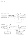
- Fig. 10 is a schematic view showing a reaction mechanism of the fuel cell system according to the fourth embodiment.
- a fuel cell system 401 includes a PEFC 420, a reaction container 403, a controller 404, a capacitor 405, a charging power source 415, a hydrogen supply mechanism 407, and a first liquefier tank 440 and a second liquefier tank 443 for storing a gasified hydrogen occlusion material 406.
- the reaction container 403 and the PEFC 420 communicate with each other via a hydrogen flow path 408 that is connected to the side of a fuel electrode 421, and a first hydrogen separation membrane 416 is provided on the hydrogen flow path 408. Furthermore, the reaction container 403 and the first liquefier tank 440 communicate with each other via a first flow path 441 and a second flow path 442, with the first flow path 441 branching off from the hydrogen flow path 408 at the first hydrogen separation membrane 416 and communicating with the first liquefier tank 440. Furthermore, the reaction container 403 and the second liquefier tank 443 communicate with each other via a third flow path 444 and a fourth flow path 445. Furthermore, an oxygen supply line 425 is connected to the side of an oxygen electrode 422.
- the reaction container 403 and the hydrogen supply mechanism 407 communicate with each other by way of a hydrogen supply line 412, and hydrogen is supplied from the hydrogen supply mechanism 407 into the reaction container 403 via the hydrogen supply line 412.
- a valve (not shown) is provided, and these valve mechanisms allow hydrogen supply into the reaction container 403 and oxygen supply to the oxygen electrode 422 to be controlled.
- an organic hydride, C 6 H 12 is provided inside the reaction container 403, as the reversible hydrogen occlusion material 406, an organic hydride, C 6 H 12 .
- the organic hydride, C 6 H 12 emits hydrogen during power generation and stores hydrogen during charging based on the following reactions.
- power generation C 6 H 12 (g) ⁇ C 6 H 6 (g) + 3H 2
- charging C 6 H 6 (g) + 3H 2 ⁇ C 6 H 12 (g)
- the reaction container 403 Since these reactions of dehydrogenation and hydrogenation are endothermic reactions that require a relatively high temperature, a temperature adjustment mechanism for heating the inside of the reaction container 403 to a high temperature is required, and to that end, the reaction container 403 is provided with a heater 414.
- the capacitor 405 is used to provide an external voltage for the heater 414.
- the capacitor 405 is connected to the charging power source 415 and to the PEFC 420, and part of electricity generated in the PEFC 420 is stored in the capacitor 405.
- C 6 H 6 generated by the dehydrogenation reaction of C 6 H 12 during power generation is in a gasified state and is therefore conveyed together with hydrogen to the hydrogen flow path 408 where C 6 H 6 is separated from the hydrogen by use of the first hydrogen separation membrane 416, after which C 6 H 6 passes through the first flow path 441 to be stored in the first liquefier tank 440. Then, during charging, C 6 H 6 in the first liquefier tank 440 is gasified and supplied in that state into the reaction container 403 via the second flow path 442.
- C 6 H 12 generated by the hydrogenation reaction of C 6 H 6 during charging is also in the form of a gas
- C 6 H 12 generated in the reaction container 403 is supplied to the second liquefier tank 443 via the third flow path 444 and stored in a liquefied state in the second liquefier tank 443.
- C 6 H 12 in the second liquefier tank 443 is gasified and supplied in that state into the reaction container 403 via the fourth flow path 445.
- the controller 404 is connected to the heater 414, to the charging power source 415, and to, though not shown, each of the valves on the hydrogen supply line 412, the oxygen supply line 425, the second flow path 442, the third flow path 444, and the fourth flow path 445 and controls an adjustment of heating by the heater 414, driving of the hydrogen supply mechanism 407 by the charging power source 415, and opening and closing of the valves.
- the valve on the hydrogen supply line 412 is closed, while the valve on the fourth flow path 445 is opened so that C 6 H 12 in the second liquefier tank 443 is supplied into the reaction container 403, and the inside of the reaction container 403 is heated by the heater 414, so that hydrogen is generated from the hydrogen occlusion material 406.
- the first hydrogen separation membrane 416 provided on the hydrogen flow path 408 is supplied to the fuel electrode, while C 6 H 6 in a gasified state, after being separated from the hydrogen by use of the first hydrogen separation membrane 416, passes through the first flow path 441 to be supplied to the first liquefier tank 440.
- oxygen electrode 422 oxygen is supplied thereto by opening the valve of the oxygen supply line 425, and by electrochemical reactions at the fuel electrode 421 and at the oxygen electrode 422, the PEFC 420 generates power.
- the heating by the heater 414 is stopped, and the supply of the organic hydride into the reaction container 403 is stopped by closing the valve on the fourth flow path 445, while the oxygen supply to the oxygen electrode 422 is stopped by closing the valve on the oxygen supply line 425, so that the electrochemical reactions of the PEFC 420 are stopped.
- the present invention is favorably applicable as a power source for electronic equipment without any limitation on the form of use thereof.
Abstract
A fuel cell system (101) comprising a fuel cell (120) and a reaction container (103), wherein the fuel cell (120) comprises a fuel electrode (121), an air electrode (122) and an electrolyte film (123) and the reaction container (103) comprises a hydrogen storage material (106) and a heater (114) and can supply hydrogen to the fuel cell (120), and wherein a water flow path (109) for supplying water produced in the air electrode (122) to the reaction container (103) is provided.
Description
- The present invention relates to a reaction container that allows reactions of a fuel cell to be controlled and a fuel cell system equipped with the same.
- In recent years, along with an improvement in performance of electronic equipment, there has been a growing demand for a cell having a larger capacity and a longer life. Conventional lithium-ion cells are limited in capacity since they have almost reached their theoretical limits of an energy density per volume and, therefore, can hardly be expected to achieve any further significant improvement in performance. With this being the situation, attention has been focused on a fuel cell that is significantly improved in energy density per volume compared with conventional cells and thus can achieve an increased capacity.
- For example,
Patent Document 1 proposes a regenerative fuel cell system.Fig. 11 is a schematic view showing a reaction mechanism of a fuel cell during power generation, andFig. 12 is a schematic view showing a reaction mechanism of the fuel cell during charging. Afuel cell 520 described inPatent Document 1 is composed of afuel electrode 521, anoxygen electrode 522, and anelectrolyte membrane 523. At the time of power generation, upon supply of hydrogen to thefuel electrode 521, protons and electrons are generated from the hydrogen, and the protons move from thefuel electrode 521 through theelectrolyte membrane 523 to theoxygen electrode 522. At theoxygen electrode 522, oxide ions generated from oxygen react with the protons that have moved thereto to generate water, and by these electrochemical reactions, motive power is generated. Furthermore, at the time of charging, upon application of voltages of opposite polarities to thefuel electrode 521 and to theoxygen electrode 522, respectively, reactions reverse to the reactions that occur during power generation occur at thefuel electrode 521 and at theoxygen electrode 522, respectively, so that hydrogen is generated at thefuel electrode 521, and oxygen is generated at theoxygen electrode 522. The fuel cell system described inPatent Document 1 performs charging by taking the hydrogen generated at thefuel electrode 521 into a hydrogen occlusion material and power generation by emitting the hydrogen thus taken thereinto. - Patent Document 1:
JP-A-2002-151094 - Generally speaking, however, the reaction of storing hydrogen in a hydrogen occlusion material and the reaction of emitting hydrogen therefrom are endothermic reactions that require a high temperature, and thus, in order for the reactions to progress, it is required to heat the hydrogen occlusion material so as to accelerate the reactions. To this end, some type of reaction adjustment mechanism should be provided in a reaction container in which the hydrogen occlusion material is housed. The fuel cell system described in
Patent Document 1, however, has given no consideration to a reaction adjustment mechanism for this purpose and is, therefore, conceivably unable to perform charging and discharging in a continuously repeated manner. - In order to solve the above-described problem, it is an object of the present invention to provide a reaction container that, in a fuel cell system, allows reactions of starting and stopping charging and discharging to be controlled and the fuel cell system equipped with the reaction container.
- In order to achieve the above-described object, the present invention provides a reaction container that supplies hydrogen to a fuel cell including: a fuel electrode; an oxygen electrode; and an electrolyte membrane that is disposed between the fuel electrode and the oxygen electrode. The reaction container has a hydrogen occlusion material provided therein and is provided with at least one of a temperature adjustment mechanism and an internal pressure adjustment mechanism.
- According to this configuration, an internal condition in the reaction container is adjusted by the temperature adjustment mechanism or the internal pressure adjustment mechanism, and thus conditions for starting and stopping reactions of the hydrogen occlusion material can be controlled. Thus, during power generation, hydrogen can be emitted stably from the hydrogen occlusion material, and during charging, hydrogen can be stored stably in the hydrogen occlusion material.
- Furthermore, in the present invention, in the reaction container configured as above, the temperature adjustment mechanism includes at least one of a heater and a heat-insulated structure.
- According to this configuration, the reactions of the hydrogen occlusion material can be controlled by adjusting heating by the heater. Furthermore, when the heat-insulated structure is used as the temperature adjustment mechanism, thermal efficiency of the reaction container as a whole can be increased.
- Furthermore, in the present invention, in the reaction container configured as above, as the internal pressure adjustment mechanism, at least one of a valve mechanism and a pump is provided.
- According to this configuration, the amount of a gas to be supplied that is intended to react with the hydrogen occlusion material and the discharge of products generated by the reactions of the hydrogen occlusion material can be adjusted by use of a valve or the pump.
- Furthermore, in the present invention, in the reaction container configured as above, the hydrogen occlusion material is constituted by at least any one of iron, aluminum, and magnesium.
- According to this configuration, in a case where the hydrogen occlusion material is constituted by iron, hydrogen can be emitted by utilizing an oxidation reaction between the iron and water, and hydrogen can be stored by reducing iron oxide resulting from the oxidation with hydrogen. Similarly, oxidation and reduction reactions of aluminum or magnesium also allow hydrogen emission and occlusion.
- Furthermore, in the present invention, in the reaction container configured as above, the hydrogen occlusion material is prepared by being subjected to crushing so as to have an increased real surface area and then by forming minute cracks therein by hydrogen embrittlement, into which a sintering material is added by liquid phase deposition.
- According to this configuration, reaction activity of the hydrogen occlusion material is enhanced, and thus hydrogen emission and occlusion can be performed stably. The above-described addition of a sintering material into any metallic hydrogen occlusion material can provide a similar effect.
- Furthermore, in the present invention, in the reaction container configured as above, a water supply mechanism for supplying water to the reaction container is provided.
- According to this configuration, water is supplied from the water supply mechanism to the reaction container, and thus the reaction between the hydrogen occlusion material and water can be accelerated.
- Furthermore, in the present invention, in the reaction container configured as above, the water supply mechanism is provided with a valve mechanism.
- According to this configuration, the amount of water to be supplied to the reaction container is adjusted by the valve mechanism, and thus the reaction between the hydrogen occlusion material and water can be controlled.
- Furthermore, in the present invention, in the reaction container configured as above, water generated in the fuel cell is supplied to the reaction container via the water supply mechanism.
- According to this configuration, water generated during electrochemical reactions of the fuel cell is removed, and thus the electrochemical reactions of the fuel cell can be accelerated. Furthermore, water generated in the fuel cell is used in the reaction container, and thus there is no need to newly provide a device for supplying water, thereby allowing size reduction of an apparatus as a whole.
- Furthermore, in the present invention, in the reaction container configured as above, a water discharging mechanism for discharging water generated by a reaction of the hydrogen occlusion material is provided.
- According to this configuration, water generated in the reaction of the hydrogen occlusion material is discharged from the water discharging mechanism, and thus the reaction of the hydrogen occlusion material can be accelerated.
- Furthermore, in the present invention, in the reaction container configured as above, the water discharging mechanism utilizes a partial pressure difference of water vapor.
- According to this configuration, water vapor generated by the reaction of the hydrogen occlusion material can be discharged efficiently from the reaction container.
- Furthermore, in the present invention, in the reaction container configured as above, the water discharging mechanism discharges water generated by cooling of water vapor.
- According to this configuration, since water vapor generated by the reaction of the hydrogen occlusion material is liquefied easily compared with other types of gases that build up in the reaction container, by utilizing this fact, water vapor can be discharged efficiently from the reaction container.
- Furthermore, in the present invention, in the reaction container configured as above, the water discharging mechanism uses a water absorbent.
- According to this configuration, by use of a water absorbent, water vapor can be discharged efficiently from the reaction container.
- Furthermore, in the present invention, in the reaction container configured as above, the water discharging mechanism performs electrolysis of water and discharges oxygen by use of an oxygen permeable membrane.
- According to this configuration, hydrogen can be generated from water vapor generated by the reaction of the hydrogen occlusion material, and thus a reaction of the hydrogen occlusion material can be accelerated.
- Furthermore, in the present invention, in the reaction container configured as above, the hydrogen occlusion material is constituted by one of an organic hydride and a metal hydride.
- According to this configuration, by use of an organic hydride or a metal hydride, hydrogen occlusion and emission can be performed efficiently.
- Furthermore, in the present invention, in the reaction container configured as above, the hydrogen occlusion material is constituted by a complex hydride.
- According to this configuration, by use of a complex hydride, hydrogen occlusion and emission can be performed efficiently.
- Furthermore, in the present invention, in the reaction container configured as above, the hydrogen occlusion material is constituted by a carbon material.
- According to this configuration, by use of a carbon material, hydrogen occlusion and emission can be performed efficiently. Examples of a carbon material include a carbon nanotube.
- Furthermore, in the present invention, in the reaction container configured as above, a hydrogen supply mechanism for supplying hydrogen to the reaction container is provided.
- According to this configuration, during charging, hydrogen is supplied from the hydrogen supply mechanism to the reaction container and can be stored in the reaction container.
- Furthermore, in the present invention, in the reaction container configured as above, the hydrogen supply mechanism is provided with a valve mechanism.
- According to this configuration, the amount of hydrogen to be supplied from the hydrogen supply mechanism to the reaction container is adjusted by use of a valve, and thus the amount of hydrogen to be stored in the reaction container can be controlled. Furthermore, during power generation by the fuel cell, hydrogen supply to the reaction container is stopped, and during charging of the fuel cell, the hydrogen supply to the reaction container is started, whereby power generation by and charging of the fuel cell can be controlled.
- Furthermore, in the present invention, in the reaction container configured as above, the hydrogen supply mechanism is provided with a hydrogen separation membrane.
- According to this configuration, only hydrogen can be supplied form the hydrogen supply mechanism to the reaction container.
- Furthermore, in the present invention, in the reaction container configured as above, the hydrogen supply mechanism generates hydrogen by electrolysis of water.
- According to this configuration, hydrogen can be generated easily from water, and thus a fuel for generating hydrogen can be obtained easily.
- Furthermore, in the present invention, in the reaction container configured as above, the hydrogen supply mechanism generates hydrogen by a water decomposition reaction of a photocatalyst.
- According to this configuration, hydrogen can be generated merely by irradiation with light and used to perform charging.
- Furthermore, in the present invention, in the reaction container configured as above, surface plasmon resonance is used as an excitation source for the photocatalyst.
- According to this configuration, a water decomposition reaction of a photocatalyst is further activated, and thus the generation of hydrogen can be accelerated.
- Furthermore, in the present invention, as a material of the reaction container configured as above, any one of Si, glass, ceramic, metal, and plastic is used.
- According to this configuration, a reaction container having excellent resistance to heat and pressure can be provided.
- Furthermore, the present invention also provides a fuel cell system having the reaction container configured as above and the fuel cell. In the fuel cell system, the fuel cell is any one of a solid oxide fuel cell (SOFC), a polymer electrolyte fuel cell (PEFC), a phosphoric acid fuel cell (PAFC), and an alkaline fuel cell (AFC).
- According to this configuration, a fuel cell system can be provided in which hydrogen storage in the reaction container and hydrogen supply to the reaction container are performed stably and that thus is continuously regenerative.
- Furthermore, in the present invention, in the fuel cell system configured as above, in the fuel cell, when a negative voltage is applied to the fuel electrode and a positive voltage is applied to the oxygen electrode, reactions reverse to reactions that occur during power generation occur at the fuel electrode and at the oxygen electrode, respectively.
- According to this configuration, hydrogen can be generated at the fuel cell by such reverse reactions of the fuel cell. The hydrogen thus generated is supplied to and stored in the reaction container, thereby allowing charging of the fuel cell to be performed.
- Furthermore, in the present invention, the fuel cell system configured as above has a capacitor.
- According to this configuration, electricity generated in the fuel cell can be charged in the capacitor. Furthermore, the capacitor can be used as a power source for the temperature adjustment mechanism, the internal pressure adjustment mechanism, and the hydrogen supply mechanism.
- Furthermore, in the present invention, the fuel cell system configured as above has a lithium-ion cell.
- According to this configuration, electricity generated in the fuel cell can be charged in the lithium-ion cell. Furthermore, the lithium-ion cell can be used as a power source for the temperature adjustment mechanism, the internal pressure adjustment mechanism, and the hydrogen supply mechanism.
- According to the present invention, there can be provided a reaction container that is capable of controlling reactions of a reversible hydrogen occlusion material and a fuel cell system that supplies hydrogen to a fuel cell by use of the reaction container.
-
- [
Fig. 1 ] is schematic view showing part of a fuel cell system according to a first embodiment. - [
Fig. 2 ] is a schematic view showing a water discharging mechanism. - [
Fig. 3 ] is a schematic view showing a water discharging mechanism. - [
Fig. 4 ] is a schematic view showing a water discharging mechanism. - [
Fig. 5 ] is a schematic structural view of a fuel cell system according to a second embodiment. - [
Fig. 6 ] is a schematic view showing a reaction mechanism of the fuel cell system according to the second embodiment. - [
Fig. 7 ] is a schematic structural view of a fuel cell system according to a third embodiment. - [
Fig. 8 ] is a schematic view showing a reaction mechanism of the fuel cell system according to the third embodiment. - [
Fig. 9 ] is a schematic structural view of a fuel cell system according to a fourth embodiment. - [
Fig. 10 ] is a schematic view showing a reaction mechanism of the fuel cell system according to the fourth embodiment. - [
Fig. 11 ] is a schematic view showing a reaction mechanism of a fuel cell during power generation. - [
Fig. 12 ] is a schematic view showing a reaction mechanism of the fuel cell during charging. - The following describes in detail a fuel cell system according to the present invention with reference to the appended drawings.
-
Fig. 1 is a schematic view showing part of a fuel cell system according to a first embodiment. Afuel cell system 101 includes a polymer electrolyte fuel cell 120 (hereinafter, abbreviated as PEFC), areaction container 103, and anair chamber 124. ThePEFC 120 is composed of afuel electrode 121, anelectrolyte membrane 123, and anoxygen electrode 122, with afuel diffusion layer 121a formed on thefuel electrode 121 on the side of thereaction container 103 and anair diffusion layer 122a formed on theoxygen electrode 122 on the side of theair chamber 124. A firsthydrogen separation membrane 116 is provided between thereaction container 103 and thefuel electrode 121, and inside thereaction container 103, as ahydrogen occlusion material 106, iron particles are provided at a predetermined position. Furthermore, thereaction container 103 adopts a two-tier structure in which acavity 170 is provided between an outer wall and an inner wall and is provided with aheater 114 for heating the inside of thereaction container 103. - The
reaction container 103 communicates with ahydrogen supply line 112, and hydrogen is supplied into thereaction container 103 via thehydrogen supply line 112. Furthermore, thereaction container 103 communicates with awater discharge line 113, and water is discharged out of thereaction container 103 via thewater discharge line 113. Thehydrogen supply line 112 and thewater discharge line 113 are provided with avalve 112a and avalve 113a, respectively, and these valve mechanisms allow water supply into thereaction container 103 and water discharge out of thereaction container 103 to be controlled. - The
air chamber 124, on the other hand, communicates with anoxygen supply line 125, and oxygen is supplied into theair chamber 124 via theoxygen supply line 125. Furthermore, theoxygen supply line 125 is provided with avalve 125a, and this allows air supply into theair chamber 124 to be controlled. Furthermore, theair chamber 124 and thereaction container 103 communicate with each other via awater flow path 109, and a gas-liquid separation filter 110 and apump 111 are provided on thewater flow path 109. Water generated at theoxygen electrode 122 is subjected to separation by the gas-liquid separation filter 110, and resulting water is supplied to thereaction container 103 via thepump 111. Thewater flow path 109, the gas-liquid separation filter 110, and thepump 111 represent one example of the "water supply mechanism" of the present invention. - The
hydrogen occlusion material 106 is constituted by iron particles, and the following oxidation and reduction reactions occur in thereaction container 103.
Oxidation reaction: 3Fe + 4H2O → Fe3O4 + 4H2
Reduction reaction: Fe3O4 + 4H2 → 3Fe + 4H2O
- By these reactions, during power generation, the
hydrogen occlusion material 106 emits hydrogen based on an oxidation reaction of iron, and during charging, it stores hydrogen based on a reduction reaction of iron oxide. Although the oxidation and reduction reactions of thehydrogen occlusion material 106 are endothermic reactions that require a high temperature, theheater 114 is used to adjust a temperature inside thereaction container 103, and thus the reactions of thehydrogen occlusion material 106 can be controlled. By use of the firsthydrogen separation membrane 116 formed between thereaction container 103 and thefuel electrode 121, only hydrogen is separated from a gas containing water vapor and so on and then supplied to thefuel electrode 121. - In the
PEFC 120, during power generation, the following reactions occur at thefuel electrode 121 and at theoxygen electrode 122, respectively, so that at thefuel electrode 121, protons and electrons are generated from hydrogen, and at theoxygen electrode 122, the protons that have moved thereto from thefuel electrode 121 and oxide ions generated from oxygen react with each other to generate water.
Fuel electrode: H2 → 2H+ + 2e-
Oxygen electrode: 4H+ + O2 + 4e- → 2H2O
- Furthermore, upon application of voltages of opposite polarities to the
fuel electrode 121 and theoxygen electrode 122, respectively, reactions reverse to the reactions that occur during power generation occur at thefuel electrode 121 and at theoxygen electrode 122, respectively.
Fuel electrode: 2H+ + 2e- → H2
Oxygen electrode: 2H2O → 4H+ + O2 + 4e-
- Next, the following describes a method of operation of the
fuel cell system 101. At the time of power generation, thereaction container 103 is sealed by closing thevalve 112a of thehydrogen supply line 112 and thevalve 113a on thewater discharge line 113, and the inside thereof is heated by theheater 114, so that in thereaction container 103, an oxidation reaction of iron constituting thehydrogen occlusion material 106 occurs to generate hydrogen. The hydrogen is then supplied through the firsthydrogen separation membrane 116 to thefuel electrode 121. - Meanwhile, in the
air chamber 124, oxygen is supplied to theoxygen electrode 122 by opening thevalve 125a of theoxygen supply line 125, so that water is generated, and by these electrochemical reactions in thereaction container 103 and in theair chamber 124, thePEFC 120 generates power. Furthermore, water generated in theair chamber 124 is supplied into thereaction container 103 via thewater flow path 109. - In a case of bringing the
fuel cell system 101 to a halt, the reaction of thehydrogen occlusion material 106 is stopped by stopping the heating by theheater 114, and the oxygen supply is stopped by closing thevalve 125a of theoxygen supply line 125, so that the electrochemical reactions of thePEFC 120 are stopped. - Furthermore, in a case of charging the
fuel cell system 101, thevalve 112a on thehydrogen supply line 112 and thevalve 113a on thewater discharge line 113 are opened, and the inside of thereaction container 103 is heated by theheater 114. This causes hydrogen supplied through thehydrogen supply line 112 into thereaction container 103 to reduce iron oxide and thus to be stored in thehydrogen occlusion material 106. Furthermore, in thereaction container 103, a water discharging mechanism is provided that is connected to thewater discharge line 113, and thus water vapor generated in the reduction reaction of iron oxide is discharged thereby out of thereaction container 103, and thus the reduction reaction can be accelerated. -
Fig. 2 is a schematic view showing one example of the water discharging mechanism, and as shown inFig. 2 , awater discharging mechanism 117 is composed of acirculation path 130 and acooling portion 131. Thecirculation path 130 communicates at one end with thewater discharge line 113 and at the other end with thehydrogen supply line 112, and the coolingportion 131 is provided on thecirculation path 130. Part of hydrogen supplied through thehydrogen supply line 112 into thereaction container 103 reacts with iron oxide constituting thehydrogen occlusion material 106 to generate water vapor, and the residual part of the hydrogen left without contributing to the reaction and the water vapor flow through thewater discharge line 113 into thecirculation path 130. The water vapor contained in a gas that has thus flowed thereinto is cooled to be liquefied and separated in the coolingportion 131. The hydrogen contained in the gas passes through the coolingportion 131 and flows through thehydrogen supply line 112 into thereaction container 103. As described above, the residual part of hydrogen left without reacting with thehydrogen occlusion material 106 circulates in thecirculation path 130 and thus prevents a decrease in hydrogen concentration in thereaction container 103, so that the reduction reaction between thehydrogen occlusion material 106 and hydrogen is accelerated. A Peltier device can be used as the coolingportion 131, and providing the coolingportion 131 with a water-repellent structure allows liquefied water to be discharged efficiently. -
Fig. 3 is a schematic view showing one example of the water discharging mechanism, and as shown inFig. 3 , a configuration is possible in which in thewater discharging mechanism 117, a watervapor separation membrane 132 is provided at some point in thecirculation path 130 so that water vapor is removed by use thereof.Fig. 4 is a schematic view showing one example of the water discharging mechanism, and as shown inFig. 4 , a configuration is possible in which anelectrolysis bath 134 and an oxygenpermeable membrane 133 are provided on thecirculation path 130 so that circulating water vapor is separated into oxygen and hydrogen by electrolysis and thus is removed. At this time, the oxygen is eliminated by use of the oxygenpermeable membrane 133, and the resulting hydrogen is made to flow again into thereaction container 103, so that the reduction reaction between thehydrogen occlusion material 106 and hydrogen can be accelerated. Furthermore, in addition to the above, a method utilizing a partial pressure difference of water vapor or a method using a water absorbent may be used to remove water vapor. - Although this embodiment uses the
PEFC 120 as a fuel cell, any one of a solid oxide fuel cell (hereinafter, abbreviated as SOFC), a phosphoric acid fuel cell (hereinafter, abbreviated as PAFC), and an alkaline fuel cell (hereinafter, abbreviated as AFC) may be used as a fuel cell. In a case of using a fuel cell in which, during power generation, water is generated at thefuel electrode 121, such as an SOFC, it is not required that theair chamber 124 and thereaction container 103 communicate with each other by way of thewater flow path 109. - As the
hydrogen occlusion material 106, iron in the form of iron particles is used, which is prepared by being subjected to crushing so as to have an increased real surface area and then by forming minute cracks therein by hydrogen embrittlement, into which a sintering material is added by liquid phase deposition. By this treatment, reactivity of the oxidation and reduction reactions between iron and water is enhanced, and thus in thereaction container 103, hydrogen emission and occlusion are performed stably. - Furthermore, although this embodiment uses iron as the reversible
hydrogen occlusion material 106, hydrogen occlusion materials of other types than iron can also be used to perform hydrogen emission and occlusion, and the use of aluminum or magnesium can bring about a similar reaction. - Furthermore, as a hydrogen occlusion material, an organic hydride or a metal hydride, a complex hydride, a carbon material, a hydrogen occlusion material based on a hydration reaction, and an alloy-based hydrogen occlusion material can also be used. Furthermore, as a material of the
reaction container 103, any one of Si, glass, ceramic, metal, and plastic is used, and a material having excellent resistance to heat, chemicals, and pressure can be used favorably. - Next, the following describes a second embodiment of the fuel cell system according to the present invention with reference to the appended drawings. In the following, duplicate descriptions of components identical to those in the fuel cell system according to the first embodiment are omitted.
Fig. 5 is a schematic structural view of a fuel cell system according to the second embodiment of the present invention, andFig. 6 is a schematic view showing a reaction mechanism of the fuel cell system according to the second embodiment. Afuel cell system 201 includes aPEFC 220, areaction container 203 that supplies hydrogen to thePEFC 220, acontroller 204 that performs control of the entirefuel cell system 201, acapacitor 205, a chargingpower source 215, and ahydrogen supply mechanism 207 that, during charging, supplies hydrogen to thereaction container 203. - The
reaction container 203 and thePEFC 220 communicate with each other by way of ahydrogen flow path 208 and awater flow path 209, and thehydrogen flow path 208 is connected to the side of afuel electrode 221 of thePEFC 220, while thewater flow path 209 is connected to the side of anoxygen electrode 222 of thePEFC 220. Furthermore, a firsthydrogen separation membrane 216 is provided on thehydrogen flow path 208 and used to supply only hydrogen separated from a gas containing water vapor and so on to thefuel electrode 221. A gas-liquid separation filter 210 and a pump 211 are provided on thewater flow path 209. Water vapor generated at theoxygen electrode 222 is liquefied, after which only water is separated from the water vapor thus liquefied by the gas-liquid separation filter 210, and water vapor obtained by gasifying the water by use of a gasifier is supplied to thereaction container 303. Furthermore, anoxygen supply line 225 is connected to the side of theoxygen electrode 222. - The
reaction container 203 and thehydrogen supply mechanism 207 communicate with each other by way of ahydrogen supply line 212 and awater discharge line 213, and a secondhydrogen separation membrane 218 is provided on thehydrogen supply line 212. By use of the secondhydrogen separation membrane 218, only hydrogen is supplied from thehydrogen supply mechanism 207 to thereaction container 203 via thehydrogen supply line 212, and water inside thereaction container 203 is supplied to thehydrogen supply mechanism 207 via thewater discharge line 213. - Furthermore, the
hydrogen supply line 212, thewater discharge line 213, and theoxygen supply line 225 are each provided with a valve (not shown), and these valve mechanisms allow hydrogen supply into thereaction container 203, water discharge out of thereaction container 203, and oxygen supply to theoxygen electrode 222 to be controlled. - A
heater 214 adjusts a temperature inside thereaction container 203 so as to control reactions of ahydrogen occlusion material 206. Thecapacitor 305 is used to provide an external voltage for theheater 214. Furthermore, thecapacitor 205 is connected to the chargingpower source 215 and to thePEFC 220, and part of electricity generated in thePEFC 220 is stored therein. As the chargingpower source 215, a lithium-ion cell can be used. - The
controller 204 is connected to theheater 214, to the chargingpower source 215, to the pump 211, and to, though not shown, each of the valves on thehydrogen supply line 212, thewater discharge line 213, and theoxygen supply line 225 and controls an adjustment of heating by theheater 214, driving of thehydrogen supply mechanism 207 by the chargingpower source 215, and opening and closing of the valves. Specifically, at the time of power generation, thereaction container 203 is sealed by closing the valve on thehydrogen supply line 212 and the valve on thewater discharge line 213, and the inside thereof is heated by theheater 214, so that an oxidation reaction of iron constituting thehydrogen occlusion material 206 is caused to generate hydrogen. At this time, only hydrogen that has permeated through the firsthydrogen separation membrane 216 provided on thehydrogen flow path 208 is supplied to thefuel electrode 221. Furthermore, at theoxygen electrode 222, oxygen is supplied thereto by opening the valve of theoxygen supply line 225, and by electrochemical reactions at thefuel electrode 221 and at theoxygen electrode 222, thePEFC 220 generates power. Furthermore, by the pump 211, water generated at theoxygen electrode 222 is conveyed through thewater flow path 209 to thereaction container 203. - At the time of stopping the power generation, the heating by the
heater 214 is stopped, and the oxygen supply to theoxygen electrode 222 is stopped by closing the valve on theoxygen supply line 225, so that the electrochemical reactions of thePEFC 220 are stopped. - Furthermore, at the time of charging, with the valve on the
hydrogen supply line 212 and the valve on thewater discharge line 213 opened, the inside of thereaction container 203 is heated by theheater 214, and a voltage is applied from the chargingpower source 215 to thehydrogen supply mechanism 207. This causes hydrogen generated in thehydrogen supply mechanism 207 to be supplied into thereaction container 203 via thehydrogen supply line 212, and thehydrogen occlusion material 206 then occludes the hydrogen. These mechanisms of adjusting a temperature and an internal pressure in thereaction container 203 are controlled by thecontroller 204, and thus hydrogen emission and storage by the reversiblehydrogen occlusion material 206 are performed stably, thereby allowing charging and discharging of thePEFC 220 to be controlled. - In the above-described
fuel cell system 201, the oxidation reaction between iron and water that occurs in thereaction container 203 during power generation uses water generated at theoxygen electrode 222 during power generation by thePEFC 220. By discharging water generated at theoxygen electrode 222 during power generation in this manner, the electrochemical reaction that occurs at theoxygen electrode 222 during power generation is prevented from being impaired, and the oxidation reaction between iron and water in thereaction container 203 can be accelerated. - Furthermore, during charging, water generated in the
reaction container 203 is discharged actively through thewater discharge line 213, and thus the reduction reaction that occurs in thereaction container 203 is accelerated, so that the reaction can be made to progress even in a case where a temperature in thereaction container 203 is relatively low. At this time, the water discharging mechanism described with regard to the first embodiment can be used to eliminate water through thewater discharge line 213. Furthermore, thehydrogen supply mechanism 207 is a mechanism that generates hydrogen by electrolysis of water, and as water to be subjected to the electrolysis, water generated in thereaction container 203 during charging is used and supplied from thereaction container 203 to thehydrogen supply mechanism 207 via thewater discharge line 213. As a power source used for the electrolysis, the chargingpower source 215 is used. - Furthermore, the
hydrogen supply mechanism 207 according to the present invention is not limited to the mechanism utilizing electrolysis of water and may utilize a water decomposition reaction of a photocatalyst. Since in a water decomposition reaction of a photocatalyst, hydrogen can be generated by irradiating the photocatalyst with natural light, there is no need to connect thehydrogen supply mechanism 207 to the chargingpower source 215. The use of surface plasmon resonance as an excitation source for the photocatalyst is preferable in that it activates a water decomposition reaction of a photocatalyst and thus can accelerate the generation of hydrogen. - Next, the following describes a third embodiment of the fuel cell system according to the present invention with reference to the appended drawings. In the following, duplicate descriptions of components identical to those in the fuel cell systems according to the first and second embodiments are omitted.
Fig. 7 is a schematic structural view of a fuel cell system according to the third embodiment of the present invention, andFig. 8 is a schematic view showing a reaction mechanism of the fuel cell system according to the third embodiment. Afuel cell system 301 includes aPEFC 320, areaction container 303, acontroller 304, acapacitor 305, a chargingpower source 315, and ahydrogen supply mechanism 307. - The
reaction container 303 and thePEFC 320 communicate with each other by way of ahydrogen flow path 308 that is connected to the side of afuel electrode 321, and a firsthydrogen separation membrane 316 is provided on thehydrogen flow path 308. Furthermore, anoxygen supply line 325 is connected to the side of anoxygen electrode 322. - The
reaction container 303 and thehydrogen supply mechanism 307 communicate with each other by way of ahydrogen supply line 312, and a secondhydrogen separation membrane 318 is provided on thehydrogen supply line 312. By use thereof, only hydrogen is supplied from thehydrogen supply mechanism 307 into thereaction container 303. On each of thehydrogen supply line 312 and theoxygen supply line 325, a valve (not shown) is provided, and these valve mechanisms allow hydrogen supply into thereaction container 303 and oxygen supply to theoxygen electrode 322 to be controlled. - Inside the
reaction container 303, as a reversiblehydrogen occlusion material 306, a complex hydride, Mg(BH4)2, is provided, which emits hydrogen during power generation and stores hydrogen during charging based on the following reactions. During power generation: Mg(BH4)2 → MgH2 + 2B + 3H2
: MgH2 → Mg + H2
During charging: MgH2 + 2B + 3H2 → Mg(BH4)2 : Mg + H2 → MgH2
- Since these reactions of hydrogen emission and hydrogen occlusion are endothermic reactions that require a relatively high temperature, a temperature adjustment mechanism for heating the inside of the
reaction container 303 to a high temperature is required, and to that end, thereaction container 303 is provided with aheater 314. Thecapacitor 305 is used to provide an external voltage for theheater 314. Thecapacitor 305 is connected to the chargingpower source 315 and to thePEFC 320, and part of electricity generated in thePEFC 320 is stored in thecapacitor 305. - The
controller 304 is connected to theheater 314, to the chargingpower source 315, and to, though not shown, each of the valves on thehydrogen supply line 312 and theoxygen supply line 325 and controls an adjustment of heating by theheater 314, driving of thehydrogen supply mechanism 307 by the chargingpower source 315, and opening and closing of the valves. Specifically, at the time of power generation, thereaction container 303 is sealed by closing the valve on thehydrogen supply line 312, and the inside thereof is heated by theheater 314, so that a reaction of thehydrogen occlusion material 306 is caused to generate hydrogen. At this time, only hydrogen that has permeated through the firsthydrogen separation membrane 316 provided on thehydrogen flow path 308 is supplied to thefuel electrode 321. Furthermore, at theoxygen electrode 322, oxygen is supplied thereto by opening the valve of theoxygen supply line 325, and by electrochemical reactions at thefuel electrode 321 and at theoxygen electrode 322, thePEFC 320 generates power. - At the time of stopping the power generation, the heating by the
heater 314 is stopped, and the oxygen supply to theoxygen electrode 322 is stopped by closing the valve on theoxygen supply line 325, so that the electrochemical reactions of thePEFC 320 are stopped. - Furthermore, at the time of charging, with the valve on the
hydrogen supply line 312 opened, the inside of thereaction container 303 is heated by theheater 314, and a voltage is applied from the chargingpower source 315 to thehydrogen supply mechanism 307. This causes hydrogen generated in thehydrogen supply mechanism 307 to be supplied into thereaction container 303 via thehydrogen supply line 312, and thehydrogen occlusion material 306 then occludes the hydrogen. These mechanisms of adjusting a temperature and an internal pressure in thereaction container 303 are controlled by thecontroller 304, and thus hydrogen emission and storage by the reversiblehydrogen occlusion material 306 are performed stably, thereby allowing charging and discharging of thePEFC 320 to be controlled. - In the
fuel cell system 301, as shown inFig. 8 , the following is also possible. That is, water vapor generated at theoxygen electrode 322 during power generation is stored in a liquefied state so as to be used in thehydrogen supply mechanism 307 during charging. By discharging water generated at theoxygen electrode 322 during power generation in this manner, the electrochemical reaction that occurs at theoxygen electrode 322 during power generation can be prevented from being impaired, and water to be used for thehydrogen supply mechanism 307 can be secured in thefuel cell system 301. - Next, the following describes a fourth embodiment of the fuel cell system according to the present invention with reference to the appended drawings. In the following, duplicate descriptions of components identical to those in the fuel cell systems according to the first to third embodiments are omitted.
Fig. 9 is a schematic structural view of a fuel cell system according to the fourth embodiment of the present invention, andFig. 10 is a schematic view showing a reaction mechanism of the fuel cell system according to the fourth embodiment. Afuel cell system 401 includes aPEFC 420, areaction container 403, acontroller 404, acapacitor 405, a chargingpower source 415, ahydrogen supply mechanism 407, and afirst liquefier tank 440 and asecond liquefier tank 443 for storing a gasifiedhydrogen occlusion material 406. - The
reaction container 403 and thePEFC 420 communicate with each other via ahydrogen flow path 408 that is connected to the side of afuel electrode 421, and a firsthydrogen separation membrane 416 is provided on thehydrogen flow path 408. Furthermore, thereaction container 403 and thefirst liquefier tank 440 communicate with each other via afirst flow path 441 and asecond flow path 442, with thefirst flow path 441 branching off from thehydrogen flow path 408 at the firsthydrogen separation membrane 416 and communicating with thefirst liquefier tank 440. Furthermore, thereaction container 403 and thesecond liquefier tank 443 communicate with each other via athird flow path 444 and a fourth flow path 445. Furthermore, anoxygen supply line 425 is connected to the side of anoxygen electrode 422. - The
reaction container 403 and thehydrogen supply mechanism 407 communicate with each other by way of ahydrogen supply line 412, and hydrogen is supplied from thehydrogen supply mechanism 407 into thereaction container 403 via thehydrogen supply line 412. On each of thehydrogen supply line 412 and theoxygen supply line 425, a valve (not shown) is provided, and these valve mechanisms allow hydrogen supply into thereaction container 403 and oxygen supply to theoxygen electrode 422 to be controlled. - Inside the
reaction container 403, as the reversiblehydrogen occlusion material 406, an organic hydride, C6H12, is provided. Herein, the organic hydride, C6H12, emits hydrogen during power generation and stores hydrogen during charging based on the following reactions.
During power generation: C6H12(g) → C6H6 (g) + 3H2
During charging: C6H6 (g) + 3H2 → C6H12(g)
- Since these reactions of dehydrogenation and hydrogenation are endothermic reactions that require a relatively high temperature, a temperature adjustment mechanism for heating the inside of the
reaction container 403 to a high temperature is required, and to that end, thereaction container 403 is provided with aheater 414. Thecapacitor 405 is used to provide an external voltage for theheater 414. Thecapacitor 405 is connected to the chargingpower source 415 and to thePEFC 420, and part of electricity generated in thePEFC 420 is stored in thecapacitor 405. - Furthermore, C6H6 generated by the dehydrogenation reaction of C6H12 during power generation is in a gasified state and is therefore conveyed together with hydrogen to the
hydrogen flow path 408 where C6H6 is separated from the hydrogen by use of the firsthydrogen separation membrane 416, after which C6H6 passes through thefirst flow path 441 to be stored in thefirst liquefier tank 440. Then, during charging, C6H6 in thefirst liquefier tank 440 is gasified and supplied in that state into thereaction container 403 via thesecond flow path 442. - Furthermore, C6H12 generated by the hydrogenation reaction of C6H6 during charging is also in the form of a gas, and C6H12 generated in the
reaction container 403 is supplied to thesecond liquefier tank 443 via thethird flow path 444 and stored in a liquefied state in thesecond liquefier tank 443. Then, during power generation, C6H12 in thesecond liquefier tank 443 is gasified and supplied in that state into thereaction container 403 via the fourth flow path 445. By eliminating C6H6 or C6H12 generated in thereaction container 403 in the above-described manner, the dehydrogenation reaction of C6H12 or the hydrogenation reaction of C6H6 can be accelerated. - The
controller 404 is connected to theheater 414, to the chargingpower source 415, and to, though not shown, each of the valves on thehydrogen supply line 412, theoxygen supply line 425, thesecond flow path 442, thethird flow path 444, and the fourth flow path 445 and controls an adjustment of heating by theheater 414, driving of thehydrogen supply mechanism 407 by the chargingpower source 415, and opening and closing of the valves. Specifically, at the time of power generation, the valve on thehydrogen supply line 412 is closed, while the valve on the fourth flow path 445 is opened so that C6H12 in thesecond liquefier tank 443 is supplied into thereaction container 403, and the inside of thereaction container 403 is heated by theheater 414, so that hydrogen is generated from thehydrogen occlusion material 406. At this time, only hydrogen that has permeated through the firsthydrogen separation membrane 416 provided on thehydrogen flow path 408 is supplied to the fuel electrode, while C6H6 in a gasified state, after being separated from the hydrogen by use of the firsthydrogen separation membrane 416, passes through thefirst flow path 441 to be supplied to thefirst liquefier tank 440. Meanwhile, at theoxygen electrode 422, oxygen is supplied thereto by opening the valve of theoxygen supply line 425, and by electrochemical reactions at thefuel electrode 421 and at theoxygen electrode 422, thePEFC 420 generates power. - At the time of stopping the power generation, the heating by the
heater 414 is stopped, and the supply of the organic hydride into thereaction container 403 is stopped by closing the valve on the fourth flow path 445, while the oxygen supply to theoxygen electrode 422 is stopped by closing the valve on theoxygen supply line 425, so that the electrochemical reactions of thePEFC 420 are stopped. - Furthermore, at the time of charging, with the valve on the
hydrogen supply line 412, the valve on thesecond flow path 442, and the valve on thethird flow path 444 opened, the inside of thereaction container 403 is heated by theheater 414, and a voltage is applied from the chargingpower source 415 to thehydrogen supply mechanism 407. This causes hydrogen to be supplied from thehydrogen supply mechanism 407 through thehydrogen supply line 412 into thereaction container 403 and C6H6 to be supplied from thefirst liquefier tank 440 into thereaction container 403, and by the hydrogenation reaction, C6H12 is generated. Then, C6H12 thus generated is supplied to thesecond liquefier tank 443 via thethird flow path 444. These mechanisms of adjusting a temperature and an internal pressure in thereaction container 403 are controlled, and thus hydrogen emission and occlusion by the reversiblehydrogen occlusion material 406 are performed stably, thereby allowing charging and discharging of thePEFC 420 to be controlled. - The present invention is favorably applicable as a power source for electronic equipment without any limitation on the form of use thereof.
-
- 101, 201
- fuel cell system
- 103, 203
- reaction container
- 204
- controller
- 205
- capacitor
- 106, 206
- hydrogen occlusion material
- 207
- hydrogen supply mechanism
- 208
- hydrogen flow path
- 109, 209
- water flow path
- 210
- gas-liquid separation filter
- 111, 211
- pump
- 112, 212
- hydrogen supply line
- 113, 213
- water discharge line
- 114,214
- heater
- 215
- charging power source
- 116,216
- first hydrogen separation membrane
- 117
- water discharging mechanism
- 218
- second hydrogen separation membrane
- 120, 220
- PEFC (fuel cell)
- 121,221
- fuel electrode
- 121a
- fuel diffusion layer
- 122, 222
- oxygen electrode
- 122a
- air diffusion layer
- 123, 223
- electrolyte membrane
- 125, 225
- oxygen supply line
- 124
- air chamber
- 130
- circulation path
- 131
- cooling portion
- 132
- water vapor separation membrane
- 133
- oxygen permeable membrane
- 160
- gasifiier
- 170
- cavity
- 440
- first liquefier tank
- 441
- first flow path
- 442
- second flow path
- 443
- second liquefier tank
- 444
- third flow path
- 445
- fourth flow path
Claims (27)
- A reaction container that supplies hydrogen to a fuel cell, the fuel cell comprising:a fuel electrode;an oxygen electrode; andan electrolyte membrane that is disposed between the fuel electrode and the oxygen electrode,wherein
the reaction container has a hydrogen occlusion material provided therein, and
at least one of a temperature adjustment mechanism and an internal pressure adjustment mechanism is provided. - The reaction container according to claim 1, wherein
the temperature adjustment mechanism includes at least one of a heater and a heat-insulated structure. - The reaction container according to claim 1 or 2, wherein
as the internal pressure adjustment mechanism, at least one of a valve mechanism and a pump is provided. - The reaction container according to any one of claims 1 to 3, wherein
the hydrogen occlusion material is constituted by at least any one of iron, aluminum, and magnesium. - The reaction container according to claim 4, wherein
the hydrogen occlusion material is prepared by being subjected to crushing so as to have an increased real surface area and then by forming minute cracks therein by hydrogen embrittlement, into which a sintering material is added by liquid phase deposition. - The reaction container according to claim 4 or 5, wherein
a water supply mechanism for supplying water to the reaction container is provided. - The reaction container according to claim 6, wherein
the water supply mechanism is provided with a valve mechanism. - The reaction container according to claim 6 or 7, wherein
water generated in the fuel cell is supplied to the reaction container via the water supply mechanism. - The reaction container according to any one of claims 4 to 8, wherein
a water discharging mechanism for discharging water generated by a reaction of the hydrogen occlusion material is provided. - The reaction container according to claim 9, wherein
the water discharging mechanism utilizes a partial pressure difference of water vapor. - The reaction container according to claim 9, wherein
the water discharging mechanism discharges water generated by cooling of water vapor. - The reaction container according to claim 9, wherein
the water discharging mechanism uses a water absorbent. - The reaction container according to claim 9, wherein
the water discharging mechanism performs electrolysis of water and discharges oxygen by use of an oxygen permeable membrane. - The reaction container according to any one of claims 1 to 3, wherein
the hydrogen occlusion material is constituted by one of an organic hydride and a metal hydride. - The reaction container according to any one of claims 1 to 3, wherein
the hydrogen occlusion material is constituted by a complex hydride. - The reaction container according to any one of claims 1 to 3, wherein
the hydrogen occlusion material is constituted by a carbon material. - The reaction container according to any one of claims 1 to 16, wherein
a hydrogen supply mechanism for supplying hydrogen to the reaction container is provided. - The reaction container according to claim 17, wherein
the hydrogen supply mechanism is provided with a valve mechanism. - The reaction container according to claim 17 or 18, wherein
the hydrogen supply mechanism is provided with a hydrogen separation membrane. - The reaction container according to any one of claims 17 to 19, wherein
the hydrogen supply mechanism generates hydrogen by electrolysis of water. - The reaction container according to any one of claims 17 to 19, wherein
the hydrogen supply mechanism generates hydrogen by a water decomposition reaction of a photocatalyst. - The reaction container according to claim 21, wherein
surface plasmon resonance is used as an excitation source for the photocatalyst. - The reaction container according to any one of claims 1 to 22, wherein
as a material of the reaction container, any one of Si, glass, ceramic, metal, and plastic is used. - A fuel cell system, comprising:the reaction container according to any one of claims 1 to 23; andthe fuel cell,whereinthe fuel cell is any one of a solid oxide fuel cell (SOFC), a polymer electrolyte fuel cell (PEFC), a phosphoric acid fuel cell (PAFC), and an alkaline fuel cell (AFC).
- The fuel cell system according to claim 24, wherein
in the fuel cell, when a negative voltage is applied to the fuel electrode and a positive voltage is applied to the oxygen electrode, reactions reverse to reactions that occur during power generation occur at the fuel electrode and at the oxygen electrode, respectively. - The fuel cell system according to claim 24 or 25, further comprising a capacitor.
- The fuel cell system according to any one of claims 24 to 26, further comprising a lithium-ion cell.
Applications Claiming Priority (2)
| Application Number | Priority Date | Filing Date | Title |
|---|---|---|---|
| JP2009292082 | 2009-12-24 | ||
| PCT/JP2010/072207 WO2011077969A1 (en) | 2009-12-24 | 2010-12-10 | Reaction container and fuel cell system equipped with same |
Publications (1)
| Publication Number | Publication Date |
|---|---|
| EP2518809A1 true EP2518809A1 (en) | 2012-10-31 |
Family
ID=44195501
Family Applications (1)
| Application Number | Title | Priority Date | Filing Date |
|---|---|---|---|
| EP10839203A Withdrawn EP2518809A1 (en) | 2009-12-24 | 2010-12-10 | Reaction container and fuel cell system equipped with same |
Country Status (4)
| Country | Link |
|---|---|
| US (1) | US8637198B2 (en) |
| EP (1) | EP2518809A1 (en) |
| JP (1) | JPWO2011077969A1 (en) |
| WO (1) | WO2011077969A1 (en) |
Cited By (2)
| Publication number | Priority date | Publication date | Assignee | Title |
|---|---|---|---|---|
| WO2013110509A3 (en) * | 2012-01-25 | 2013-10-17 | Siemens Aktiengesellschaft | Electrical energy store |
| EP2835853A4 (en) * | 2012-04-03 | 2015-11-18 | Konica Minolta Inc | Fuel cell system |
Families Citing this family (14)
| Publication number | Priority date | Publication date | Assignee | Title |
|---|---|---|---|---|
| EP2571087A4 (en) * | 2010-05-11 | 2015-12-09 | Konica Minolta Holdings Inc | Fuel cell device |
| JP5168431B2 (en) * | 2011-01-20 | 2013-03-21 | コニカミノルタホールディングス株式会社 | Secondary battery type solid oxide fuel cell system |
| US20130316254A1 (en) * | 2011-03-08 | 2013-11-28 | Panasonic Corporation | Energy system |
| EP2808930A4 (en) * | 2012-01-24 | 2015-10-07 | Konica Minolta Inc | Secondary battery type fuel cell system |
| EP2827425A4 (en) * | 2012-03-12 | 2015-11-18 | Konica Minolta Inc | Secondary cell-type fuel cell system |
| JP2013214398A (en) * | 2012-04-02 | 2013-10-17 | Konica Minolta Inc | Method of manufacturing fuel cell system |
| JP5210450B1 (en) * | 2012-11-07 | 2013-06-12 | 直芳 可知 | Fuel cell and fuel cell system |
| JP6040512B2 (en) * | 2015-03-31 | 2016-12-07 | 株式会社エクォス・リサーチ | Solar power system |
| JP6040511B2 (en) * | 2015-03-31 | 2016-12-07 | 株式会社エクォス・リサーチ | Solar power system |
| WO2017135451A1 (en) * | 2016-02-04 | 2017-08-10 | Connexx Systems株式会社 | Fuel cell |
| DE112017005355T5 (en) | 2016-10-24 | 2019-07-11 | Precision Combustion, Inc. | Solid oxide fuel cell with internal reformer |
| JP6573863B2 (en) * | 2016-10-28 | 2019-09-11 | 東京瓦斯株式会社 | Multistage fuel cell system |
| WO2019008799A1 (en) * | 2017-07-04 | 2019-01-10 | 株式会社Ihi | Hydrogen–oxygen reaction device |
| CN114566687B (en) * | 2021-12-27 | 2024-01-23 | 徐州华清京昆能源有限公司 | Power generation system of solid oxide fuel cell |
Family Cites Families (31)
| Publication number | Priority date | Publication date | Assignee | Title |
|---|---|---|---|---|
| US4204033A (en) | 1979-01-02 | 1980-05-20 | Massachusetts Institute Of Technology | Electrical cell construction |
| JPH08183602A (en) * | 1994-12-28 | 1996-07-16 | Power Reactor & Nuclear Fuel Dev Corp | Production of hydrogen |
| US5492777A (en) | 1995-01-25 | 1996-02-20 | Westinghouse Electric Corporation | Electrochemical energy conversion and storage system |
| EP0813264A3 (en) * | 1996-06-14 | 2004-02-25 | Matsushita Electric Industrial Co., Ltd. | Fuel cell system, fuel feed system for fuel cell and portable electric appliance |
| EP1032940B1 (en) * | 1997-11-20 | 2001-09-12 | Institut für Festkörper- und Werkstofforschung Dresden e.V. | Method for producing a magnetic alloy powder |
| JP2000032685A (en) | 1998-07-10 | 2000-01-28 | Shinko Pantec Co Ltd | Uninterruptible power supply system |
| JP2001065797A (en) * | 1999-09-01 | 2001-03-16 | Toyota Motor Corp | Hydrogen storage device and hydrogen storage system |
| JP2001213603A (en) * | 2000-01-28 | 2001-08-07 | Honda Motor Co Ltd | Hydrogen supply system for device using hydrogen as fuel |
| CN1241828C (en) | 2000-06-16 | 2006-02-15 | 打矢恒温器株式会社 | Method and apparatus for supplying hydrogen and portable cassette for supplying hydrogen |
| JP4887558B2 (en) | 2000-11-07 | 2012-02-29 | ソニー株式会社 | How to use the fuel cell |
| US6447945B1 (en) * | 2000-12-12 | 2002-09-10 | General Atomics | Portable electronic device powered by proton exchange membrane fuel cell |
| JP3722019B2 (en) * | 2001-06-27 | 2005-11-30 | 日産自動車株式会社 | Fuel cell system |
| JP2003227598A (en) | 2002-02-04 | 2003-08-15 | Japan Steel Works Ltd:The | Hydrogen compressor device and operating method of the device |
| JP4112304B2 (en) * | 2002-08-05 | 2008-07-02 | ウチヤ・サーモスタット株式会社 | Hydrogen generator |
| JP4128425B2 (en) * | 2002-11-01 | 2008-07-30 | ウチヤ・サーモスタット株式会社 | Hydrogen generator |
| US7045238B2 (en) * | 2003-03-24 | 2006-05-16 | Ion America Corporation | SORFC power and oxygen generation method and system |
| JP4523241B2 (en) | 2003-04-24 | 2010-08-11 | セイコーインスツル株式会社 | Fuel cell |
| US7150927B2 (en) * | 2003-09-10 | 2006-12-19 | Bloom Energy Corporation | SORFC system with non-noble metal electrode compositions |
| JP2005255505A (en) * | 2004-03-15 | 2005-09-22 | Kurita Water Ind Ltd | Hydrogen supply method |
| JP2005289680A (en) * | 2004-03-31 | 2005-10-20 | Toho Gas Co Ltd | Hydrogen production apparatus and hydrogen production method |
| JP4594649B2 (en) * | 2004-05-28 | 2010-12-08 | ウチヤ・サーモスタット株式会社 | Hydrogen generating medium and hydrogen production method |
| JP2006179276A (en) * | 2004-12-22 | 2006-07-06 | Nitto Denko Corp | Heating system of hydrogen gas generation unit, electromagnetic induction heating unit, and hydrogen gas generation unit |
| US7295723B2 (en) * | 2005-07-20 | 2007-11-13 | Searete Llc | Plasmon photocatalysis |
| JP5169224B2 (en) | 2006-02-03 | 2013-03-27 | 日産自動車株式会社 | Hydrogen generation system, fuel cell system, and fuel cell vehicle |
| EP1990595A1 (en) * | 2006-03-01 | 2008-11-12 | Matsushita Electric Industrial Co., Ltd. | Method of heat accumulation and heat accumulation system |
| JP5024721B2 (en) * | 2006-05-10 | 2012-09-12 | トヨタ自動車株式会社 | Fuel cell system and circulation ratio calculation method thereof |
| GB2445218B (en) * | 2006-09-21 | 2011-05-25 | Smith International | Atomic layer deposition nanocoating on cutting tool powder materials |
| JP2008121096A (en) * | 2006-11-15 | 2008-05-29 | Mitsubishi Electric Corp | Method for reducing metal oxide, and method for producing hydrogen |
| KR100790688B1 (en) * | 2006-12-26 | 2008-01-02 | 삼성전기주식회사 | Fuel cell having a hydrogen storage tank |
| JP4659075B2 (en) * | 2007-09-28 | 2011-03-30 | バイオコーク技研株式会社 | Power generator |
| EP2485311A4 (en) * | 2009-09-30 | 2014-05-07 | Konica Minolta Holdings Inc | Fuel cell device |
-
2010
- 2010-12-10 JP JP2011547468A patent/JPWO2011077969A1/en active Pending
- 2010-12-10 EP EP10839203A patent/EP2518809A1/en not_active Withdrawn
- 2010-12-10 US US13/519,122 patent/US8637198B2/en not_active Expired - Fee Related
- 2010-12-10 WO PCT/JP2010/072207 patent/WO2011077969A1/en active Application Filing
Cited By (2)
| Publication number | Priority date | Publication date | Assignee | Title |
|---|---|---|---|---|
| WO2013110509A3 (en) * | 2012-01-25 | 2013-10-17 | Siemens Aktiengesellschaft | Electrical energy store |
| EP2835853A4 (en) * | 2012-04-03 | 2015-11-18 | Konica Minolta Inc | Fuel cell system |
Also Published As
| Publication number | Publication date |
|---|---|
| JPWO2011077969A1 (en) | 2013-05-02 |
| WO2011077969A1 (en) | 2011-06-30 |
| US8637198B2 (en) | 2014-01-28 |
| US20120288775A1 (en) | 2012-11-15 |
Similar Documents
| Publication | Publication Date | Title |
|---|---|---|
| US8637198B2 (en) | Reaction container and fuel cell system equipped with same | |
| US6592741B2 (en) | Fuel gas generation system and generation method thereof | |
| KR20170015976A (en) | Electrolysis method and electrolysis system comprising recirculating flushing media | |
| US8426073B2 (en) | Fuel cell system and method of controlling same | |
| JP2007517372A (en) | Fuel cell startup method using fuel purge | |
| US20120295171A1 (en) | Fuel Cell System | |
| US20070148528A1 (en) | Fuel cell generating system | |
| JP3623409B2 (en) | Fuel cell | |
| US20090226776A1 (en) | Hydrogen charging apparatus | |
| US8053128B2 (en) | Apparatus for solid-oxide fuel cell shutdown having a timing circuit and a reservoir | |
| CN108666601A (en) | Electric light charging is flushed with hydrogen fuel cell | |
| JP5509895B2 (en) | Fuel cell | |
| JP2004281393A (en) | Fuel cell power generation system | |
| US20090263690A1 (en) | Apparatus for generating hydrogen and fuel cell power generation system having the same | |
| JP6378508B2 (en) | Fuel cell system | |
| US11777122B2 (en) | Hydrogen generator with carbon capture for use with a hydrogen fuel cell | |
| JPH02132766A (en) | Stopping method for fuel cell system | |
| KR20220064198A (en) | Fuel cell system | |
| JP2008034319A (en) | Solid methanol fuel cartridge for direct methanol type fuel cell, direct methanol type fuel cell system, and portable electronic apparatus | |
| WO2014192795A1 (en) | Secondary-cell-type fuel cell system | |
| JPH02132771A (en) | Fuel cell system | |
| KR20240023785A (en) | Reforming type fuel cell system using low boiling point and operating method thereof. | |
| JP2020200211A (en) | Hydrogen production apparatus and its operation method | |
| JP5497265B2 (en) | Discharge system for fuel cell inspection | |
| KR20080046306A (en) | Apparatus and method for activating electric generator of fuel cell system |
Legal Events
| Date | Code | Title | Description |
|---|---|---|---|
| PUAI | Public reference made under article 153(3) epc to a published international application that has entered the european phase |
Free format text: ORIGINAL CODE: 0009012 |
|
| 17P | Request for examination filed |
Effective date: 20120622 |
|
| AK | Designated contracting states |
Kind code of ref document: A1 Designated state(s): AL AT BE BG CH CY CZ DE DK EE ES FI FR GB GR HR HU IE IS IT LI LT LU LV MC MK MT NL NO PL PT RO RS SE SI SK SM TR |
|
| DAX | Request for extension of the european patent (deleted) | ||
| STAA | Information on the status of an ep patent application or granted ep patent |
Free format text: STATUS: THE APPLICATION IS DEEMED TO BE WITHDRAWN |
|
| 18D | Application deemed to be withdrawn |
Effective date: 20160701 |