JP3722019B2 - Fuel cell system - Google Patents
Fuel cell system Download PDFInfo
- Publication number
- JP3722019B2 JP3722019B2 JP2001194934A JP2001194934A JP3722019B2 JP 3722019 B2 JP3722019 B2 JP 3722019B2 JP 2001194934 A JP2001194934 A JP 2001194934A JP 2001194934 A JP2001194934 A JP 2001194934A JP 3722019 B2 JP3722019 B2 JP 3722019B2
- Authority
- JP
- Japan
- Prior art keywords
- fuel cell
- gas
- water
- water recovery
- amount
- Prior art date
- Legal status (The legal status is an assumption and is not a legal conclusion. Google has not performed a legal analysis and makes no representation as to the accuracy of the status listed.)
- Expired - Fee Related
Links
Images


Classifications
-
- H—ELECTRICITY
- H01—ELECTRIC ELEMENTS
- H01M—PROCESSES OR MEANS, e.g. BATTERIES, FOR THE DIRECT CONVERSION OF CHEMICAL ENERGY INTO ELECTRICAL ENERGY
- H01M8/00—Fuel cells; Manufacture thereof
- H01M8/04—Auxiliary arrangements, e.g. for control of pressure or for circulation of fluids
- H01M8/04082—Arrangements for control of reactant parameters, e.g. pressure or concentration
- H01M8/04089—Arrangements for control of reactant parameters, e.g. pressure or concentration of gaseous reactants
- H01M8/04119—Arrangements for control of reactant parameters, e.g. pressure or concentration of gaseous reactants with simultaneous supply or evacuation of electrolyte; Humidifying or dehumidifying
-
- H—ELECTRICITY
- H01—ELECTRIC ELEMENTS
- H01M—PROCESSES OR MEANS, e.g. BATTERIES, FOR THE DIRECT CONVERSION OF CHEMICAL ENERGY INTO ELECTRICAL ENERGY
- H01M8/00—Fuel cells; Manufacture thereof
- H01M8/04—Auxiliary arrangements, e.g. for control of pressure or for circulation of fluids
- H01M8/04007—Auxiliary arrangements, e.g. for control of pressure or for circulation of fluids related to heat exchange
- H01M8/04029—Heat exchange using liquids
-
- H—ELECTRICITY
- H01—ELECTRIC ELEMENTS
- H01M—PROCESSES OR MEANS, e.g. BATTERIES, FOR THE DIRECT CONVERSION OF CHEMICAL ENERGY INTO ELECTRICAL ENERGY
- H01M2250/00—Fuel cells for particular applications; Specific features of fuel cell system
- H01M2250/20—Fuel cells in motive systems, e.g. vehicle, ship, plane
-
- H—ELECTRICITY
- H01—ELECTRIC ELEMENTS
- H01M—PROCESSES OR MEANS, e.g. BATTERIES, FOR THE DIRECT CONVERSION OF CHEMICAL ENERGY INTO ELECTRICAL ENERGY
- H01M8/00—Fuel cells; Manufacture thereof
- H01M8/04—Auxiliary arrangements, e.g. for control of pressure or for circulation of fluids
- H01M8/04082—Arrangements for control of reactant parameters, e.g. pressure or concentration
- H01M8/04089—Arrangements for control of reactant parameters, e.g. pressure or concentration of gaseous reactants
- H01M8/04119—Arrangements for control of reactant parameters, e.g. pressure or concentration of gaseous reactants with simultaneous supply or evacuation of electrolyte; Humidifying or dehumidifying
- H01M8/04156—Arrangements for control of reactant parameters, e.g. pressure or concentration of gaseous reactants with simultaneous supply or evacuation of electrolyte; Humidifying or dehumidifying with product water removal
-
- Y—GENERAL TAGGING OF NEW TECHNOLOGICAL DEVELOPMENTS; GENERAL TAGGING OF CROSS-SECTIONAL TECHNOLOGIES SPANNING OVER SEVERAL SECTIONS OF THE IPC; TECHNICAL SUBJECTS COVERED BY FORMER USPC CROSS-REFERENCE ART COLLECTIONS [XRACs] AND DIGESTS
- Y02—TECHNOLOGIES OR APPLICATIONS FOR MITIGATION OR ADAPTATION AGAINST CLIMATE CHANGE
- Y02E—REDUCTION OF GREENHOUSE GAS [GHG] EMISSIONS, RELATED TO ENERGY GENERATION, TRANSMISSION OR DISTRIBUTION
- Y02E60/00—Enabling technologies; Technologies with a potential or indirect contribution to GHG emissions mitigation
- Y02E60/30—Hydrogen technology
- Y02E60/50—Fuel cells
-
- Y—GENERAL TAGGING OF NEW TECHNOLOGICAL DEVELOPMENTS; GENERAL TAGGING OF CROSS-SECTIONAL TECHNOLOGIES SPANNING OVER SEVERAL SECTIONS OF THE IPC; TECHNICAL SUBJECTS COVERED BY FORMER USPC CROSS-REFERENCE ART COLLECTIONS [XRACs] AND DIGESTS
- Y02—TECHNOLOGIES OR APPLICATIONS FOR MITIGATION OR ADAPTATION AGAINST CLIMATE CHANGE
- Y02T—CLIMATE CHANGE MITIGATION TECHNOLOGIES RELATED TO TRANSPORTATION
- Y02T90/00—Enabling technologies or technologies with a potential or indirect contribution to GHG emissions mitigation
- Y02T90/40—Application of hydrogen technology to transportation, e.g. using fuel cells
Description
【0001】
【発明の属する技術分野】
本発明は、燃料電池システムに関し、特に、システム内で必要とされる純水の量を保持しつつ、燃料電池の効率を改善した燃料電池システムに関する。
【0002】
【従来の技術】
燃料電池システムは、燃料が有する化学エネルギを直接電気エネルギに変換する装置であり、電解質膜を挟んで設けられた一対の電極のうち陽極に水素を含有する燃料ガスを供給するとともに、他方の陰極に酸素を含有する酸化剤ガスを供給し、これら一対の電極の電解質膜側の表面で生じる下記の電気化学反応を利用して電極から電気エネルギを取り出すものである(例えば、特開平8−106914号公報参照)。
【0003】
【化1】
アノード反応:H2→2H++2e− …(1)
カソード反応:2H++2e−+(1/2)O2→H2O …(2)
アノードに供給する燃料ガスは、水素貯蔵装置から直接供給する方法、水素を含有する燃料を改質して改質した水素含有ガスを供給する方法が知られている。水素貯蔵装置としては、高圧ガスタンク、液化水素タンク、水素吸蔵合金タンク等がある。水素を含有する燃料としては、天然ガス、メタノール、ガソリン等が考えられる。カソードに供給する酸化剤ガスとしては、一般的に空気が利用されている。
【0004】
こうした燃料電池においては電解質膜の性能を引き出し、発電効率を向上させるためには、電解質膜の水分状態を最適に保つ必要がある。このため、燃料電池に導入する燃料ガス、空気を加湿することが行われる。また前述したように燃料ガスを改質して水素を取り出す場合においては、改質用に水を利用することが行なわれる。例えば、メタノールを改質して水素を取り出す場合には、以下の化学反応式(3)により水素を取り出している。
【0005】
【化2】
CH3OH+H2O→3H2+CO2 …(3)
従って、燃料電池を自動車用に利用するためには、燃料電池あるいは改質器を含めた燃料電池システム内で水収支が保たれなければならない。これは、水が不足し、定期的な純水の補給が必要となると燃料電池自動車の実用性が著しく低下するためである。
【0006】
また一方では、燃料電池を運転すると電池から熱が排出される。このため、燃料電池には水等の冷媒を流し、ラジエータ等の熱交換器を用いる冷却装置を設置し、電池からの発熱を車外に放出している。この際の、車外に放出できる熱の量は外気温や車速等の影響を受ける。従って、電池の発熱量が冷却装置の放熱量を上回ると燃料電池の温度が上昇し、運転を続けることが困難になる。よって、燃料電池システムは熱収支が保たれなければならない。
【0007】
【発明が解決しようとする課題】
燃料電池システムの水収支に関する従来技術として、特開平10−172599号公報には、燃料電池の運転圧力を制御することにより水収支を成立させる技術が開示されている。この従来技術によれば、外気温度が高くなった場合には、燃料電池システムから排出される排出ガス含まれる水の量が増加し、システムの水収支が成立しなくなる。この場合に燃料電池の運転圧力を増加させて、燃料電池から排出される水の量を減らすように制御している。しかしながら、運転圧力を増加したガスに含まれる気相の水を液相の水として回収する場合には、水の凝縮熱が発生し、燃料電池システムから外部へ放熱すべき熱量が増加する。このため水収支を改善するために運転圧力を増加していくと、前述した熱収支が成立しなくなり、燃料電池の運転継続が困難になるという問題点があった。
【0008】
以上の問題点に鑑み、本発明の目的は、燃料電池システムの水収支と熱収支を同時に成立させ、しかも効率良く燃料電池を運転することができる燃料電池システムを提供することにある。
【0009】
【課題を解決するための手段】
請求項1記載の発明は、上記課題を解決するために、加湿機能及び水回収機能を有する燃料電池本体と、燃料電池本体に水素含有ガスを供給する水素供給系と、燃料電池本体に酸素含有ガスを供給する酸素供給系と、燃料電池本体の温度を制御する冷却装置と、燃料電池本体に水を供給する水供給装置と、を有する燃料電池システムにおいて、前記燃料電池本体の発熱量を予測する発熱量予測手段と、前記冷却装置の冷却性能を予測する冷却性能予測手段と、前記予測された発熱量及び前記予測された冷却性能に基づいて燃料電池本体の温度を予測する温度予測手段と、前記燃料電池本体の水回収量を予測する水回収量予測手段と、前記予測された燃料電池本体の温度及び前記予測された水回収量に基づいて前記燃料電池本体の水回収量を制御する水回収量制御手段と、を備えたことを要旨とする。
【0010】
請求項2記載の発明は、上記課題を解決するために、燃料電池本体と、燃料電池本体に水素含有ガスを供給する水素供給系と、燃料電池本体に酸素含有ガスを供給する酸素供給系と、燃料電池本体に供給するガスを加湿する加湿する加湿装置と、燃料電池本体から排出されたガスから水を回収する水回収装置と、燃料電池本体及び前記加湿装置及び前記水回収装置の少なくとも一つに水を供給する水供給装置と、燃料電池本体及び前記加湿装置及び前記水回収装置の温度を制御する冷却装置と、を有する燃料電池システムにおいて、前記燃料電池本体の発熱量を予測する発熱量予測手段と、前記冷却装置の冷却性能を予測する冷却性能予測手段と、前記予測された発熱量及び前記予測された冷却性能に基づいて燃料電池システムの温度を予測する温度予測手段と、前記燃料電池本体の水回収量を予測する水回収量予測手段と、前記予測された燃料電池本体の温度及び前記予測された水回収量に基づいて前記燃料電池本体の水回収量を制御する水回収量制御手段と、を備えたことを要旨とする。
【0011】
請求項3記載の発明は、上記課題を解決するために、請求項1または請求項2に記載の燃料電池システムにおいて、前記燃料電池システム入口のガス量、ガス温度、ガス湿度をそれぞれ検出あるいは予測する入口ガス状態取得手段を備え、前記水回収量予測手段は、燃料電池システム入口のガス量、ガス温度、ガス湿度に基づいて水回収量を予測することを要旨とする。
【0012】
請求項4記載の発明は、上記課題を解決するために、請求項3に記載の燃料電池システムにおいて、前記燃料電池システム出口のガス温度を検出あるいは予測する出口ガス温度取得手段を更に備え、前記水回収量予測手段は、燃料電池システム入口のガス量、ガス温度、ガス湿度、及び燃料電池システム出口のガス温度に基づいて水回収量を予測することを要旨とする。
【0013】
請求項5記載の発明は、上記課題を解決するために、請求項3に記載の燃料電池システムにおいて、前記燃料電池システム出口のガス量、ガス温度、ガス湿度を検出あるいは予測する出口ガス状態取得手段を更に備え、前記水回収量予測手段は、燃料電池システム入口及び出口のガス量、ガス温度、ガス湿度に基づいて水回収量を予測することを要旨とする。
【0015】
請求項6記載の発明は、上記課題を解決するために、請求項1ないし請求項5のいずれか1項に記載の燃料電池システムにおいて、前記水回収制御手段は、前記燃料電池システム内の水収支が平衡するように制御することを要旨とする。
【0016】
請求項7記載の発明は、上記課題を解決するために、請求項1ないし請求項6のいずれか1項に記載の燃料電池システムにおいて、燃料電池システム内の水量を検出する水量検出手段を備え、前記水回収量は前記燃料電池システム内の水量に応じて変化させることを要旨とする。
【0017】
請求項8記載の発明は、上記課題を解決するために、請求項1ないし請求項7のいずれか1項に記載の燃料電池システムにおいて、前記燃料電池に供給するガス圧力を制御する圧力制御手段を備え、前記水回収量は、前記ガス圧力によって制御することを要旨とする。
【0018】
請求項9記載の発明は、上記課題を解決するために、請求項1ないし請求項7のいずれか1項に記載の燃料電池システムにおいて、前記燃料電池に供給するガスの利用率を制御する利用率制御手段を備え、前記水回収量は、前記ガス利用率によって制御することを要旨とする。
【0019】
請求項10記載の発明は、上記課題を解決するために、請求項1ないし請求項7のいずれか1項に記載の燃料電池システムにおいて、前記燃料電池の出力を制御する出力制御手段を備え、前記水回収量は、前記燃料電池の出力によって制御することを要旨とする。
【0020】
請求項11記載の発明は、上記課題を解決するために、請求項1ないし請求項5のいずれか1項に記載の燃料電池システムにおいて、前記燃料電池に供給するガスの圧力および利用率を制御する圧力/利用率制御手段と、燃料電池システムの効率を予測する効率予測手段と、を備え、前記ガス圧力および利用率は燃料電池システムの効率が最大となるように制御することを要旨とする。
【0021】
【発明の効果】
請求項1記載の本発明によれば、加湿機能及び水回収機能を有する燃料電池本体と、燃料電池本体に水素含有ガスを供給する水素供給系と、燃料電池本体に酸素含有ガスを供給する酸素供給系と、燃料電池本体の温度を制御する冷却装置と、燃料電池本体に水を供給する水供給装置と、を有する燃料電池システムにおいて、前記燃料電池本体の発熱量を予測する発熱量予測手段と、前記冷却装置の冷却性能を予測する冷却性能予測手段と、前記予測された発熱量及び前記予測された冷却性能に基づいて燃料電池本体の温度を予測する温度予測手段と、前記燃料電池本体の水回収量を予測する水回収量予測手段と、前記予測された燃料電池本体の温度及び前記予測された水回収量に基づいて前記燃料電池本体の水回収量を制御する水回収量制御手段と、を備えたことにより、燃料電池システムの熱収支が成立する条件において水回収量を制御できるようになり、燃料電池の熱収支と水収支を同時に成立させる運転状態を実現することができるという効果がある。
【0022】
請求項2記載の本発明によれば、燃料電池本体と、燃料電池本体に水素含有ガスを供給する水素供給系と、燃料電池本体に酸素含有ガスを供給する酸素供給系と、燃料電池本体に供給するガスを加湿する加湿する加湿装置と、燃料電池本体から排出されたガスから水を回収する水回収装置と、燃料電池本体及び前記加湿装置及び前記水回収装置の少なくとも一つに水を供給する水供給装置と、燃料電池本体及び前記加湿装置及び前記水回収装置の温度を制御する冷却装置と、を有する燃料電池システムにおいて、前記燃料電池本体の発熱量を予測する発熱量予測手段と、前記冷却装置の冷却性能を予測する冷却性能予測手段と、前記予測された発熱量及び前記予測された冷却性能に基づいて燃料電池システムの温度を予測する温度予測手段と、前記燃料電池本体の水回収量を予測する水回収量予測手段と、前記予測された燃料電池本体の温度及び前記予測された水回収量に基づいて前記燃料電池本体の水回収量を制御する水回収量制御手段と、を備えたことにより、加湿装置と水回収装置とを燃料電池本体外部に有する燃料電池システムにおいてもシステムの熱収支が成立する条件において水回収量を制御できるようになり、燃料電池システムの熱収支と水収支を同時に成立させる運転状態を実現することができるという効果がある。
【0023】
請求項3記載の発明によれば、請求項1または請求項2に記載の発明の効果に加えて、前記燃料電池システム入口のガス量、ガス温度、ガス湿度をそれぞれ検出あるいは予測する入口ガス状態取得手段を備え、前記水回収量予測手段は、燃料電池システム入口のガス量、ガス温度、ガス湿度に基づいて水回収量を予測するようにしたので、燃料電池の水回収量を正確に予測し、水回収量の誤差を可能な限り小さくすることができるという効果がある。
【0024】
請求項4記載の発明によれば、請求項3に記載の発明の効果に加えて、前記燃料電池システム出口のガス温度を検出あるいは予測する出口ガス温度取得手段を更に備え、前記水回収量予測手段は、燃料電池システム入口のガス量、ガス温度、ガス湿度、及び燃料電池システム出口のガス温度に基づいて水回収量を予測するようにしたので、更に正確に燃料電池の水回収量を予測することができるという効果がある。
【0025】
請求項5記載の発明によれば、請求項3に記載の発明の効果に加えて、前記燃料電池システム出口のガス量、ガス温度、ガス湿度を検出あるいは予測する出口ガス状態取得手段を更に備え、前記水回収量予測手段は、燃料電池システム入口及び出口のガス量、ガス温度、ガス湿度に基づいて水回収量を予測するようにしたので、更に正確に燃料電池の水回収量を予測することができるという効果がある。
【0027】
請求項6記載の発明によれば、請求項1ないし請求項5に記載の発明の効果に加えて、前記水回収制御手段は、前記燃料電池システム内の水収支が平衡するように制御するようにしたので、環境条件等が変化した場合においても、燃料電池システムの水収支を成立させることができるという効果がある。
【0028】
請求項7記載の発明によれば、請求項1ないし請求項6に記載の発明の効果に加えて、燃料電池システム内の水量を検出する水量検出手段を備え、前記水回収量は前記燃料電池システム内の水量に応じて変化させるようにしたので、燃料電池が運転を開始した時や、システム内の水量が目標値に達しなかった場合においても、水収支を成立させることができるという効果がある。
【0029】
請求項8記載の発明によれば、請求項1ないし請求項7に記載の発明の効果に加えて、前記燃料電池に供給するガス圧力を制御する圧力制御手段を備え、前記水回収量は、前記ガス圧力によって制御するようにしたので、水回収量を精度良く制御することができるという効果がある。
【0030】
請求項9記載の発明によれば、請求項1ないし請求項7に記載の発明の効果に加えて、前記燃料電池に供給するガスの利用率を制御する利用率制御手段を備え、前記水回収量は、前記ガス利用率によって制御するようにしたので、水回収量を精度良く制御することができるという効果がある。
【0031】
請求項10記載の発明によれば、請求項1ないし請求項7に記載の発明の効果に加えて、前記燃料電池の出力を制御する出力制御手段を備え、前記水回収量は、前記燃料電池の出力によって制御するようにしたので、水回収量を精度良く制御することができるという効果がある。
【0032】
請求項11記載の発明によれば、請求項1ないし請求項5に記載の発明の効果に加えて、前記燃料電池に供給するガスの圧力および利用率を制御する圧力/利用率制御手段と、燃料電池システムの効率を予測する効率予測手段と、を備え、前記ガス圧力および利用率は燃料電池システムの効率が最大となるように制御するようにしたので、水収支を成立させつつ燃料消費率を改善することができるという効果がある。
【0033】
【発明の実施の形態】
以下、図面に基づいて本発明の実施の形態について説明する。
〔第1実施形態〕
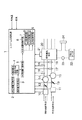
図1は本発明に係る燃料電池システムの第1の実施形態の構成を示すシステム構成図である。本実施形態においては、加湿機能及び水回収機能を有する燃料電池本体(燃料電池スタックとも呼ぶ)を備え、燃料電池本体に導入されるガス圧力を制御することによってシステムの水回収量を制御することを特徴とする。
【0034】
図1において、燃料電池システムは、燃料供給手段から供給される燃料ガス流量を検出する燃料系流量計10と、空気供給手段から供給される空気流量を検出する空気系流量計11と、燃料ガス流量を制御する燃料ガス量制御弁12と、空気流量を制御する空気量制御弁13と、燃料ガスを所望の圧力に加圧するコンプレッサ14と、空気を所望の圧力に加圧するコンプレッサ15と、燃料ガスの圧力を検出する圧力センサ16と、空気の圧力を検出する圧力センサ17と、燃料ガスの湿度を検出する湿度センサ18と、空気の湿度を検出する湿度センサ19と、燃料ガス及び空気が供給され電気化学反応により発電する燃料電池本体20と、燃料電池本体20の運転状態である出力電圧及び出力電流、或いは出力電力を検出する燃料電池運転状態検出手段21と、冷却水を貯蔵する冷却水タンク22と、冷却水を循環させる冷却水ポンプ23と、冷却水の熱をシステムの外部へ放出するラジエータ24と、これらシステム構成要素を制御するシステム制御装置1と、を備えている。
【0035】
ここで、燃料電池本体20の内部には、冷却機能に加えて、燃料極または空気極または両極の導電性多孔質部材と水分の授受を行うことにより加湿機能及び水回収機能を実現する冷却水経路が設けられている。この冷却水経路と、冷却水タンク22と、冷却水ポンプ23と、ラジエータ24とは、冷却装置を構成している。
【0036】
この冷却装置の動作は以下の通りである。冷却水ポンプ23は、冷却水タンク22から冷却水を汲み上げ、この冷却水を前記冷却水経路へ圧送する。冷却水は、冷却水経路を通過する際に燃料電池本体20から熱を吸収するとともに燃料極または空気極または両極の導電性多孔質部材と水分の授受を行う。次いで冷却水はラジエータ24からシステムの外部へ放熱して、冷却水タンク22へ戻る。
【0037】
燃料電池システムを制御するシステム制御装置1は、前記冷却装置の冷却性能を予測する冷却性能予測手段2と、燃料電池本体20の発熱量を予測する発熱量予測手段3と、予測された冷却性能及び発熱量に基づいて燃料電池本体20の温度を予測する温度予測手段4と、燃料電池本体20の水回収量を予測する水回収量予測手段5と、予測された燃料電池本体20の温度及び水回収量に基づいて水回収量を制御する水回収量制御手段6と、コンプレッサ14,15を制御することにより燃料ガス及び空気の圧力を制御する圧力制御手段7と、燃料ガスの利用率を制御する利用率制御手段8と、燃料電池の出力を制御する出力制御手段9とを備えている。
【0038】
システム制御装置1は、特に限定されないがマイクロコンピュータを内蔵し、冷却性能予測手段2、発熱量予測手段3、温度予測手段4、水回収量予測手段5、水回収量制御手段6、圧力制御手段7、利用率制御手段8、及び出力制御手段9をマイクロコンピュータのプログラム制御により実現している。
【0039】
次に、システム制御装置1の動作を説明する。システム制御装置1は、図外の外気温センサ及び車速センサからそれぞれ外気温度信号及び車速信号を入力し、外気温度及び車速に基づいて冷却性能を予測し、燃料電池運転状態から発熱量を予測する。次いで、これら予測した冷却性能及び発熱量から燃料電池温度を予測し、その温度をもとに水回収量を予測する。そして、熱収支を満足させながら要求の水回収量となるように、燃料ガス及び空気の圧力、燃料ガス利用率、燃料電池出力を制御する。
【0040】
ここで、燃料電池を効率良く運転するためには、電解質膜の水分を適切に保つ必要があり、加湿装置、水回収装置を利用する燃料電池システムがある。しかし、燃料電池システムによっては加湿装置、水回収装置を燃料電池内に持つシステムも公知である。その一例として、冷却媒体として純水を利用し、ポーラスタイプのバイポーラプレートを通して、電解質膜を加湿する燃料電池(例えば、特開平8−250130号公報)も公知である。本実施形態は加湿装置、水回収装置を燃料電池本体内に持つシステムの場合の実施形態である。
【0041】
本実施形態における燃料電池内の水収支は以下の式(4)で計算できる。
【0042】
【数3】
Wrcyc=Wproduct+Fin+Ain−Fout−Aout …(4)
ここで、
Fin :燃料極入水量
Ain :空気極入水量
Fout :燃料極排水量
Aout :空気極排水量
Wproduct:反応生成水量
Wrcyc :回収水量
とする。式(4)の回収水量(Wrcyc)が0以上となれば、燃料電池システムの水収支が成立する。
【0043】
反応生成水量(Wproduct)は、燃料電池の運転状態すなわち出力電力(または出力電流)の時間積分値である出力電力量(または出力電荷量)から算出できる。また燃料極及び空気極の入水量は、それぞれのガスの流量、圧力、温度、湿度から算出できる。燃料極及び空気極の排水量もそれぞれのガスの流量、圧力、温度、湿度から算出できる。
【0044】
本実施形態では電力量は燃料電池運転状態検出手段21から算出される。ガスの流量は流量計10,11で検出される。
圧力は燃料電池入口の圧力センサ16,17で検出している。出口圧力は入口圧力から流路の圧力損失から容易に予測できる。尚、ガス圧力はセンサを使用せずに、コンプレッサ14,15の運転状態と燃料ガス量制御弁12と空気量制御弁13との開度から予測しても良い。
【0045】
本実施形態は入口温度は外気温から算出しているが、更に正確を期するには温度センサを設けても良い。出口温度は燃料電池本体20の温度と同じとして算出している。入口湿度は湿度センサ18,19で検出している。出口湿度は水蒸気圧が飽和していると仮定して、出口温度に応じた飽和蒸気圧を用いて算出しているが、出口に湿度センサを設置しても良い。
【0046】
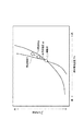
図2には燃料電池温度Tfcの変化に対して、水収支がバランスする運転圧力Pfcを示している。燃料電池温度Tfcが高くなると飽和蒸気圧が大きくなるので、水収支がバランスする圧力が高くなり、水収支バランスラインは、右肩上がりの曲線となる。そして水収支バランスラインより運転圧力が高ければ水収支は+となってシステム内の水量は増加し、水収支バランスラインより運転圧力が低ければ水収支は−となってシステム内の水量は減少する。
【0047】
従って、燃料電池システムの水収支を成立させるためには、燃料電池の温度Tfcに応じて運転圧力Pfc を制御する必要がある。尚、運転圧力は余裕代を確保して、バランス点よりもやや高い圧力で運転しても良い。
【0048】
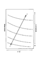
燃料電池の温度は冷却性能と発熱量から算出できる。本実施形態においては、ラジエータ24は、自然空冷式のラジエータとしているが、低速時に電力消費量の多い車両においては、電動式ラジエータファンを備えてもよい。図4には冷却性能すなわちラジエータ24の単位時間当たりの放熱量を示す。これは燃料電池の温度Tfcを一定とした場合の結果である。外気温度が低いほど、また車速が高いほどラジエータの放熱量は大きくなる。従って、図4のマップを各燃料電池の温度Tfcに対して備えておけば、放熱量を予測することができる。
【0049】
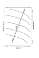
図5には燃料電池の単位時間当たりの発熱量を示す。燃料電池の発熱量は負荷(出力電力)Wが大きいほど大きくなる。また運転圧力Pfcが高くなると、燃料電池の効率が高くなるため、発熱量は小さくなる。
従って、燃料電池の負荷W、運転圧力Pfc、外気温度Tatm 、車速V等がわかれば、燃料電池の発熱量および放熱量が計算でき、熱量が釣合う燃料電池の温度を予測できる。図3は、燃料電池の負荷Wが一定の時の、冷却性能を段階的に変化させたときの発熱量=放熱量となる熱収支バランスラインを示す図である。
【0050】
図6には水収支と熱収支が成立する圧力制御点を示す。図2の水収支バランスラインと図3の熱収支バランスラインが交わる所が水収支と熱収支とを同時に満足する圧力制御点になる。このようにこれまで説明してきた方法によって、設定すべき圧力制御点を算出できる。圧力の制御は水収支、熱収支がバランスする点よりも余裕代を取ってやや高めに設定しても良い。但し、圧力を高めに設定すると水収支には有利であるが、あまり高めに設定すると水の凝縮熱が増加し熱収支が成立しなくなり、燃料電池の温度が上昇する。その結果、電解質膜の性能が低下し燃料電池の運転が困難になるため、適切な範囲に設定する。
【0051】
図7は、本実施形態における圧力制御方法を実現するフローチャートである。まず、ステップ11(以下S11)で外気温Tatm、車速Vを検出する。S12で外気温Tatm、車速Vをもとに図4のマップから放熱量を算出する。S13で燃料電池運転状態検出手段21により燃料電池の運転状態を検出する。S14で図5のマップから燃料電池の発熱量を算出する。S16で運転圧力Pfcを検出する。S17で図2、図3のマップをもとに水収支、熱収支を算出し、目標範囲にあるか判断する。水収支、熱収支ともに目標範囲にあればS19に進み、圧力Pfcはそのままとして、S11へ戻る。熱収支が目標範囲にあって水収支が目標範囲にない(NG)の場合にはS18に進み、圧力Pfcを所定値だけ増加(up)して、S11へ戻る。水収支が目標範囲にあって熱バランスが目標範囲にない(NG)の場合にはS20に進み、圧力Pfcを所定値だけ減少(down)して、S11へ戻る。
【0052】
〔第2実施形態〕
次に、第2の実施形態について説明する。第2の実施形態の構成図を図8に示す。第2の実施形態は第1実施形態の構成図に対して、冷却水量を検出するために冷却水タンク22に水位センサ25を追加したものである。第2実施形態では水位センサ25で検出した冷却水タンク22の水位に応じて圧力制御点を変える所が特徴である。
【0053】
例えば燃料電池が長期間運転されなかった場合に、水蒸気の漏れ等により、冷却水タンク22の水位が適正範囲よりも少ない場合も考えられる。このような場合には、水収支がバランスする条件よりも更に運転圧力Pfcを増加して、冷却水タンク22の水位が早く適正値に戻るようにする。
【0054】
図9に第2実施形態における圧力制御の考え方を示す。冷却水タンク22の水位が適正範囲にある場合には、水収支と熱収支がバランスする点を圧力制御点とする。これに対して、冷却水タンク22の水位が適正範囲に満たない場合には、水位の適正範囲の下限からの差に応じて運転圧力Pfcを増加し、水回収速度を増加する。これによって早い時期に冷却水タンク22の水位を適正範囲に戻すことができる。
【0055】
図10は、第2の実施形態の動作を説明する制御フローチャートである。第2の実施形態の制御フローチャートは、第1の実施形態の制御フローチャート(図7)とほぼ同様であり、異なる所のみを説明する。まず、S30で水位センサ25により冷却水タンク22の水位を検出する。S31で図9に示したような制御マップを参照して制御圧力点を算出する。S32以下の処理は、図7のS11以下の処理と同様である。
【0056】
〔第3実施形態〕
次に、第3の実施形態について説明する。第3の実施形態の構成図は第1実施形態の構成図(図1)と同じである。第3実施形態では水収支、熱収支を成立させるパラメータをガスの利用率とする所が特徴である。
【0057】
ガスの利用率を大きくすると、燃料電池を通過するガスの流量が少なくなる。従って、燃料電池からの排水量を少なくできるため、水収支をバランス点で有利である。図11は、燃料電池温度Tfcとガス利用率Ufcを変えた場合の水収支バランスラインを示す。燃料電池温度Tfcが特定の範囲内にあれば、ガス利用率Ufcによって水収支をバランスさせることができる。第1の実施形態で示したように、燃料電池の圧力を制御しても水収支、熱収支をバランスさせることができる。しかしながら、圧力を増加させると燃料電池自身の効率が高くなるが、コンプレッサ14,15等の補機の駆動仕事が増加するため、システムの効率は低下する。よってガス利用率で制御できる範囲の場合にはガス利用率を利用した方が有利である。
【0058】
このガス利用率の制御にガスの圧力制御を組み合わせて、ガス利用率で制御できなくなった場合にはガス圧力制御を利用するようにしても良い。
【0059】
図12は、第3の実施形態の動作を説明する制御フローチャートである。第3の実施形態の制御フローチャートは第1の実施形態の制御フローチャート(図7)とほぼ同様であり、異なる所のみ説明する。まず、外気温Tatm及び車速Vを検出するS51から燃料電池温度Tfcを検出するS55までは、図7のS11からS15までと同じである。次いで、S56で燃料ガスのガス利用率Ufcを検出する。S57で水収支及び熱収支のバランスを判断する。水収支及び熱収支が所定の範囲内であれば共にO.K.として、S59でガス利用率はそのままとして、S51へ戻る。水収支のバランスが所定範囲よりマイナスであれば、水バランスNGとして、S58でガス利用率Ufcを増加(up)させて、S51へ戻る。
【0060】
熱収支バランスが所定範囲を越えていれば、熱バランスNGとして、S60でガス利用率Ufcを減少(down)させて、S51へ戻る。
【0061】
〔第4実施形態〕
次に、第4の実施形態について説明する。第4の実施形態の構成図は第1実施形態の構成図(図1)と同じである。第4実施形態では水収支、熱収支を成立させるパラメータを燃料電池の出力とする所が特徴である。
【0062】
図5で示したように、燃料電池の出力を小さくすると燃料電池からの発熱量が少なくなる。その結果、燃料電池の温度が低下して、水収支をバランス点で有利となる。但し、要求される出力に対して燃料電池出力が不足する場合には、二次電池やコンデンサ等の蓄電手段からの電気で補うことになる。出力を小さくした場合には、燃料電池のからの発熱量が低下しかつ燃料電池の温度も下がるために、水収支、熱収支ともに成立することになる。
【0063】
図13は、第4の実施形態の動作を説明する制御フローチャートである。第4の実施形態の制御フローチャートは、第1の実施形態の制御フローチャート(図7)とほぼ同様であり、異なる所のみ説明する。まず、外気温Tatm及び車速Vを検出するS71から燃料電池温度Tfcを検出するS75までは、図7のS11からS15までと同じである。次いで、S76で水収支及び熱収支のバランスを判断する。水収支及び熱収支が共に所定範囲内であれば共にO.K.として、S78で燃料電池出力はそのままとして、S71へ戻る。水収支のバランスが所定範囲よりマイナスであれば、S77で燃料電池出力を減少(down)させて、S71へ戻る。水収支が設定範囲以上の場合にはS79で燃料電池出力を増加(up)させて、S71へ戻る。
【0064】
〔第5実施形態〕
次に、第5の実施形態について説明する。第5の実施形態の構成図は第1実施形態の構成図(図1)と同じである。第5実施形態では水収支、熱収支を成立させるパラメータとして、運転圧力と利用率の両方を用い、その組み合わせとしては、燃料電池システムの効率が最大となる組み合わせとする所が特徴である。
【0065】
図14にガス圧力とガス利用率に対するシステム効率を示す。前述したようにガス圧力を増加させると補機の駆動仕事が増加してシステム効率が低下する。ガス利用率を増加させると無駄ガスが低減するため効率が増加する。しかしながら適正値よりも更にガス利用率を増加すると、燃料電池で濃度過電圧が増加し、効率は低下してしまう。よって、効率が最適となるようなガス利用率が存在する。
【0066】
図15には燃料電池温度、ガス圧力およびガス利用率に対して水収支が成立する条件を示す。利用率が大きいほど、圧力が高いほど、燃料電池温度が高温の状態においても水収支が成立するようになる。
【0067】
このように図14と図15に基づくと、効率が最も高い状態で水収支、熱収支を成立させることができる利用率と圧力の組み合わせを求めることができる。
【0068】
図16は、第5の実施形態の動作を説明する制御フローチャートである。第5の実施形態の制御フローチャートは、第1実施形態の制御フローチャート(図7)、第3の実施形態の制御フローチャート(図12)とほぼ同様であり、異なる所のみ説明する。まず、外気温Tatm及び車速Vを検出するS91から燃料電池温度Tfcを検出するS95までは、図7のS11からS15までと同じである。
【0069】
次いで、S96で燃料電池の運転圧力及びガス利用率を検出する。S97で水収支及び熱収支のバランスを判断する。水収支バランスが所定範囲よりマイナスでN.G.の場合にはS98で圧力、利用率を所定値だけ増加(up)させて、S101へ進む。S97の判定で水収支及び熱収支のバランスが共に所定範囲内でO.K.の場合はS99で圧力、利用率はそのままとして、S101へ進む。S97の判定で熱収支のバランスが所定範囲を上回ってプラスでN.G.の場合にはS100で圧力、利用率を所定値だけ減少(down)させて、S101へ進む。
【0070】
次いで、S101で図14のマップをもとに効率がベストがどうか判断する。効率がベストの場合にはS102で圧力、利用率はそのままとして、S91へ戻る。S101で効率がベストでないと判断された場合にはS101で圧力、利用率の組み合わせを変更して、S91へ戻る。
【0071】
〔第6実施形態〕
次に、第6の実施形態について説明する。図17は、第6の実施形態の構成を示すシステム構成図である。第1実施形態では燃料電池の加湿、水回収を燃料電池本体20の内部で行っていた。第6の実施形態では燃料電池本体20とは別に加湿装置26及び水回収装置27を設けた点が特徴であり、加湿装置26、燃料電池本体20、水回収装置27を合わせて燃料電池システムと考えて、全体の水収支及び熱収支の制御を行う。
【0072】
図17の第6実施形態の構成図において、第1の実施形態の構成図(図1)との相違は、燃料電池本体20の上流に加湿装置26、下流に水回収装置27を設けている。また燃料電池の冷却系から水循環系が分離され、冷却系は温度制御動作だけを行い、水循環系が加湿装置26への純水供給と燃料電池本体20及び水回収装置27からの水回収を行う。このため、燃料電池システムの水収支は水循環系で制御する一方、燃料電池システムの熱収支は冷却系で制御することになる。また、水循環系と冷却系とが分離されたため、冷却系に使用する冷媒は、純水でなくてもよくなり、例えば防錆剤や不凍液を混入したロングライフクーラント(以下、LLCと略す)を利用することができる。
【0073】
水循環系は水タンク28、ポンプ29を備え、ポンプ29により水タンク28から汲み上げた純水を給水管33を介して加湿装置26へ圧送するとともに、排水管34,35により、燃料電池本体20,水回収装置27から回収した純水を水タンク28へ戻している。
【0074】
また冷却系はLLCタンク30、ポンプ31、ラジエータ32を備え、LCCタンク30からポンプ31で汲み上げられたLLCは、ラジエータ32で冷却され、水回収装置27で排ガスと熱交換し、排ガス中の水蒸気を凝縮させ、次いで燃料電池本体20の冷却水経路を通過して燃料電池本体20との熱交換を行い、最後に加湿装置26で加湿用の純水を加熱して、LLCタンク30に戻る経路を循環する。
【0075】
本実施形態における水収支、熱収支の制御方法は第1の実施形態と同じである。但し、発熱量は加湿装置26、燃料電池本体20、水回収装置27を含めた燃料電池システム全体の発熱量となる。また、燃料電池の温度は水回収装置27の出口温度となる。制御フローチャートは、第1の実施形態から第5の実施形態の制御フローと同じものを使用する。
【図面の簡単な説明】
【図1】本発明に係る燃料電池システムの第1の実施形態の構成を説明するシステム構成図である。
【図2】燃料電池温度Tfcと運転圧力Pfcに対する水収支バランスラインを説明する図である。
【図3】各冷却性能における燃料電池温度Tfcと運転圧力Pfcに対する熱収支バランスラインを説明する図である。
【図4】外気温度Tatm と車速Vに対する放熱量を説明する図である。
【図5】燃料電池負荷Wと圧力Pfcに対して燃料電池発熱量を説明する図である。
【図6】水収支、熱収支を考慮した圧力制御点を説明する図である。
【図7】第1の実施形態の動作を説明する制御フローチャートである。
【図8】本発明に係る燃料電池システムの第2の実施形態の構成を説明するシステム構成図である。
【図9】水回収速度を考慮した圧力制御点を説明する図である。
【図10】第2の実施形態の動作を説明する制御フローチャートである。
【図11】燃料電池温度Tfcと利用率Ufcに対する水収支バランスラインを説明する図である。
【図12】第3の実施形態の動作を説明する制御フローチャートである。
【図13】第4の実施形態の動作を説明する制御フローチャートである。
【図14】圧力Pfcと利用率fcに対するシステム効率を説明する図である。
【図15】各利用率における燃料電池温度Tfcと運転圧力Pfcに対する熱収支バランスラインを説明する図である。
【図16】第5の実施形態の動作を説明する制御フローチャートである。
【図17】本発明に係る燃料電池システムの第6の実施形態の構成を説明するシステム構成図である。
【符号の説明】
1…システム制御装置
2…冷却性能予測手段
3…発熱量予測手段
4…燃料電池温度予測手段
5…水回収量予測手段
6…水回収量制御手段
7…圧力制御手段
8…利用率制御手段
9…出力制御手段
10…燃料系流量計
11…空気系流量計
12…燃料ガス量制御弁
13…空気量制御弁
14、15…コンプレッサ
16、17…圧力センサ
18、19…湿度センサ
20…燃料電池本体
21…燃料電池運転状態検出手段
22…冷却水タンク
23…水ポンプ
24…ラジエータ
25…水位センサ
26…加湿装置
27…水回収装置
28…水タンク
29…ポンプ
30…LLCタンク
31…ポンプ
32…ラジエータ[0001]
BACKGROUND OF THE INVENTION
The present invention relates to a fuel cell system, and more particularly to a fuel cell system that improves the efficiency of a fuel cell while maintaining the amount of pure water required in the system.
[0002]
[Prior art]
A fuel cell system is a device that directly converts chemical energy of fuel into electrical energy, and supplies a fuel gas containing hydrogen to an anode of a pair of electrodes provided with an electrolyte membrane interposed therebetween, and the other cathode An oxidant gas containing oxygen is supplied to the electrode, and electric energy is taken out from the electrode by utilizing the following electrochemical reaction that occurs on the surface of the electrolyte membrane side of the pair of electrodes (for example, see JP-A-8-106914). No. publication).
[0003]
[1]
anodeReaction: H2→ 2H++ 2e− ... (1)
CathodeReaction: 2H++ 2e−+ (1/2) O2→ H2O ... (2)
anodeThere are known a method of supplying a fuel gas directly to a hydrogen storage device and a method of supplying a reformed hydrogen-containing gas by reforming a fuel containing hydrogen. Examples of the hydrogen storage device include a high-pressure gas tank, a liquefied hydrogen tank, and a hydrogen storage alloy tank. As the fuel containing hydrogen, natural gas, methanol, gasoline or the like can be considered.CathodeGenerally, air is used as the oxidant gas supplied to.
[0004]
In such a fuel cell, in order to draw out the performance of the electrolyte membrane and improve the power generation efficiency, it is necessary to keep the moisture state of the electrolyte membrane optimal. For this reason, humidification of the fuel gas and air introduced into the fuel cell is performed. Further, as described above, when hydrogen is extracted by reforming the fuel gas, water is used for reforming. For example, when hydrogen is extracted by reforming methanol, hydrogen is extracted by the following chemical reaction formula (3).
[0005]
[2]
CH3OH + H2O → 3H2+ CO2 ... (3)
Therefore, in order to use the fuel cell for automobiles, the water balance must be maintained in the fuel cell system including the fuel cell or the reformer. This is because the practicality of a fuel cell vehicle is significantly reduced when water is insufficient and regular pure water needs to be replenished.
[0006]
On the other hand, when the fuel cell is operated, heat is discharged from the cell. For this reason, a coolant such as water is flowed through the fuel cell, and a cooling device using a heat exchanger such as a radiator is installed to release heat generated from the battery to the outside of the vehicle. At this time, the amount of heat that can be released outside the vehicle is affected by the outside air temperature, the vehicle speed, and the like. Therefore, when the heat generation amount of the battery exceeds the heat dissipation amount of the cooling device, the temperature of the fuel cell rises and it becomes difficult to continue the operation. Therefore, the heat balance of the fuel cell system must be maintained.
[0007]
[Problems to be solved by the invention]
As a conventional technique related to the water balance of the fuel cell system, Japanese Patent Application Laid-Open No. 10-172599 discloses a technique for establishing a water balance by controlling the operating pressure of the fuel cell. According to this prior art, when the outside air temperature becomes high, the amount of water contained in the exhaust gas discharged from the fuel cell system increases, and the water balance of the system is not established. In this case, the operation pressure of the fuel cell is increased to control the amount of water discharged from the fuel cell. However, when gas phase water contained in the gas whose operating pressure has been increased is recovered as liquid phase water, heat of condensation of water is generated, and the amount of heat to be radiated from the fuel cell system to the outside increases. For this reason, if the operating pressure is increased in order to improve the water balance, the above-described heat balance is not established, and there is a problem that it is difficult to continue the operation of the fuel cell.
[0008]
In view of the above problems, an object of the present invention is to provide a fuel cell system that can establish a water balance and a heat balance of the fuel cell system at the same time, and can operate the fuel cell efficiently.
[0009]
[Means for Solving the Problems]
In order to solve the above problems, the invention according to claim 1 is a fuel cell body having a humidifying function and a water recovery function, a hydrogen supply system for supplying a hydrogen-containing gas to the fuel cell body, and an oxygen-containing fuel cell body. In a fuel cell system having an oxygen supply system that supplies gas, a cooling device that controls the temperature of the fuel cell body, and a water supply device that supplies water to the fuel cell body, the amount of heat generated by the fuel cell body is predicted A calorific value predicting means, a cooling performance predicting means for predicting the cooling performance of the cooling device, and a temperature predicting means for predicting the temperature of the fuel cell body based on the predicted calorific value and the predicted cooling performance; Water recovery amount predicting means for predicting the water recovery amount of the fuel cell main body, and controlling the water recovery amount of the fuel cell main body based on the predicted temperature of the fuel cell main body and the predicted water recovery amount. Water recovery amount control means for, and summarized in that with a.
[0010]
In order to solve the above problems, the invention according to
[0011]
According to a third aspect of the present invention, in order to solve the above problems, in the fuel cell system according to the first or second aspect, the gas amount, gas temperature, and gas humidity at the inlet of the fuel cell system are detected or predicted, respectively. In summary, the water recovery amount prediction means predicts the water recovery amount based on the gas amount, gas temperature, and gas humidity at the inlet of the fuel cell system.
[0012]
In order to solve the above-mentioned problem, the fuel cell system according to claim 4 further includes outlet gas temperature acquisition means for detecting or predicting the gas temperature at the outlet of the fuel cell system, The gist of the water recovery amount prediction means is to predict the water recovery amount based on the gas amount at the inlet of the fuel cell system, the gas temperature, the gas humidity, and the gas temperature at the outlet of the fuel cell system.
[0013]
According to a fifth aspect of the present invention, in order to solve the above-mentioned problem, in the fuel cell system according to the third aspect, an outlet gas state is obtained for detecting or predicting the gas amount, gas temperature, and gas humidity at the outlet of the fuel cell system. The water recovery amount predicting means predicts the water recovery amount based on the gas amount, gas temperature, and gas humidity at the inlet and outlet of the fuel cell system.
[0015]
Claim 6In order to solve the above-mentioned problems, the invention described in claims 1 toClaim 5The summary of the fuel cell system according to any one of the above is that the water recovery control means controls the water balance in the fuel cell system to be balanced.
[0016]
Claim 7In order to solve the above-mentioned problems, the invention described in claims 1 toClaim 6The fuel cell system according to claim 1, further comprising water amount detection means for detecting a water amount in the fuel cell system, wherein the water recovery amount is changed according to the water amount in the fuel cell system. .
[0017]
Claim 8In order to solve the above-mentioned problems, the invention described in claims 1 toClaim 7The fuel cell system according to claim 1, further comprising a pressure control unit that controls a gas pressure supplied to the fuel cell, wherein the water recovery amount is controlled by the gas pressure.
[0018]
Claim 9In order to solve the above-mentioned problems, the invention described in claims 1 toClaim 7The fuel cell system according to any one of claims 1 to 3, further comprising a utilization rate control means for controlling a utilization rate of a gas supplied to the fuel cell, wherein the water recovery amount is controlled by the gas utilization rate. To do.
[0019]
Claim 10In order to solve the above-mentioned problems, the invention described in claims 1
[0020]
Claim 11In order to solve the above-mentioned problems, the invention described in claims 1 toClaim 5In the fuel cell system according to any one of the above, pressure / utilization rate control means for controlling the pressure and utilization rate of gas supplied to the fuel cell, and efficiency prediction means for predicting the efficiency of the fuel cell system. The gas pressure and the utilization factor are controlled so as to maximize the efficiency of the fuel cell system.
[0021]
【The invention's effect】
According to the first aspect of the present invention, a fuel cell body having a humidifying function and a water recovery function, a hydrogen supply system for supplying a hydrogen-containing gas to the fuel cell body, and an oxygen for supplying an oxygen-containing gas to the fuel cell body In a fuel cell system having a supply system, a cooling device for controlling the temperature of the fuel cell main body, and a water supply device for supplying water to the fuel cell main body, a calorific value predicting means for predicting the calorific value of the fuel cell main body Cooling performance prediction means for predicting the cooling performance of the cooling device, temperature prediction means for predicting the temperature of the fuel cell main body based on the predicted heat generation amount and the predicted cooling performance, and the fuel cell main body Water recovery amount predicting means for predicting the water recovery amount of the fuel cell, and water recovery amount control for controlling the water recovery amount of the fuel cell main body based on the predicted temperature of the fuel cell main body and the predicted water recovery amount The water recovery amount can be controlled under the condition that the heat balance of the fuel cell system is established, and the operation state in which the heat balance and the water balance of the fuel cell are established simultaneously can be realized. There is an effect.
[0022]
According to the second aspect of the present invention, a fuel cell main body, a hydrogen supply system that supplies a hydrogen-containing gas to the fuel cell main body, an oxygen supply system that supplies an oxygen-containing gas to the fuel cell main body, and a fuel cell main body Humidification device for humidifying the supplied gas, water recovery device for recovering water from the gas discharged from the fuel cell main body, and supplying water to at least one of the fuel cell main body, the humidification device and the water recovery device And a cooling device for controlling the temperature of the fuel cell main body, the humidifying device, and the water recovery device, and a calorific value predicting means for predicting the calorific value of the fuel cell main body. Cooling performance prediction means for predicting the cooling performance of the cooling device; and temperature prediction means for predicting the temperature of the fuel cell system based on the predicted heat generation amount and the predicted cooling performance; Water recovery amount predicting means for predicting the water recovery amount of the fuel cell main body, and water for controlling the water recovery amount of the fuel cell main body based on the predicted temperature of the fuel cell main body and the predicted water recovery amount With the recovery amount control means, it becomes possible to control the water recovery amount under the condition that the heat balance of the system is established even in the fuel cell system having the humidifying device and the water recovery device outside the fuel cell main body, There is an effect that it is possible to realize an operation state in which the heat balance and water balance of the fuel cell system are established at the same time.
[0023]
According to the invention described in
[0024]
According to the invention described in claim 4, in addition to the effect of the invention described in
[0025]
According to the invention described in
[0027]
Claim 6According to the described invention, claims 1 toClaim 5In addition to the effects of the invention described in (2), since the water recovery control means controls the water balance in the fuel cell system to be balanced, the fuel cell system can be used even when environmental conditions change. The water balance can be established.
[0028]
Claim 7According to the described invention, claims 1 toClaim 6In addition to the effects of the invention described in (1), a water amount detection means for detecting the amount of water in the fuel cell system is provided, and the water recovery amount is changed according to the amount of water in the fuel cell system. There is an effect that the water balance can be established when the operation is started or when the amount of water in the system does not reach the target value.
[0029]
Claim 8According to the described invention, claims 1 toClaim 7In addition to the effects of the invention described in (1), the apparatus includes pressure control means for controlling the gas pressure supplied to the fuel cell, and the water recovery amount is controlled by the gas pressure. There is an effect that it can be controlled.
[0030]
Claim 9According to the described invention, claims 1 toClaim 7In addition to the effects of the invention described in (1), a utilization rate control means for controlling a utilization rate of gas supplied to the fuel cell is provided, and the water recovery amount is controlled by the gas utilization rate. There is an effect that the amount can be controlled with high accuracy.
[0031]
Claim 10According to the described invention, claims 1 toClaim 7In addition to the effects of the invention described in (1), output control means for controlling the output of the fuel cell is provided, and the water recovery amount is controlled by the output of the fuel cell. There is an effect that can be done.
[0032]
Claim 11According to the described invention, claims 1 toClaim 5In addition to the effects of the invention described in (1), the pressure / utilization rate control means for controlling the pressure and utilization rate of the gas supplied to the fuel cell, and the efficiency prediction means for predicting the efficiency of the fuel cell system, Since the gas pressure and the utilization factor are controlled so as to maximize the efficiency of the fuel cell system, there is an effect that the fuel consumption rate can be improved while the water balance is established.
[0033]
DETAILED DESCRIPTION OF THE INVENTION
Hereinafter, embodiments of the present invention will be described with reference to the drawings.
[First Embodiment]
FIG. 1 is a system configuration diagram showing the configuration of the first embodiment of the fuel cell system according to the present invention. In this embodiment, a fuel cell main body (also referred to as a fuel cell stack) having a humidifying function and a water recovery function is provided, and the water recovery amount of the system is controlled by controlling the gas pressure introduced into the fuel cell main body. It is characterized by.
[0034]
In FIG. 1, a fuel cell system includes a
[0035]
Here, in the fuel cell
[0036]
The operation of this cooling device is as follows. The cooling
[0037]
The system control device 1 that controls the fuel cell system includes a cooling
[0038]
The system control device 1 is not particularly limited, but has a built-in microcomputer. The cooling performance prediction means 2, the heat generation amount prediction means 3, the temperature prediction means 4, the water recovery amount prediction means 5, the water recovery amount control means 6, and the pressure control means. 7. Utilization rate control means 8 and output control means 9 are realized by program control of a microcomputer.
[0039]
Next, the operation of the system control apparatus 1 will be described. The system control device 1 receives an outside air temperature signal and a vehicle speed signal from an outside air temperature sensor and a vehicle speed sensor (not shown), predicts the cooling performance based on the outside air temperature and the vehicle speed, and predicts the heat generation amount from the fuel cell operation state. . Next, the fuel cell temperature is predicted from the predicted cooling performance and calorific value, and the water recovery amount is predicted based on the temperature. Then, the fuel gas and air pressure, the fuel gas utilization rate, and the fuel cell output are controlled so that the required water recovery amount is obtained while satisfying the heat balance.
[0040]
Here, in order to efficiently operate the fuel cell, it is necessary to appropriately maintain the moisture of the electrolyte membrane, and there is a fuel cell system using a humidifier and a water recovery device. However, depending on the fuel cell system, a system having a humidifier and a water recovery device in the fuel cell is also known. As an example, a fuel cell (for example, JP-A-8-250130) that uses pure water as a cooling medium and humidifies an electrolyte membrane through a porous bipolar plate is also known. This embodiment is an embodiment in the case of a system having a humidifier and a water recovery device in a fuel cell main body.
[0041]
The water balance in the fuel cell in the present embodiment can be calculated by the following equation (4).
[0042]
[Equation 3]
Wrcyc = Wproduct + Fin + Ain−Fout−Aout (4)
here,
Fin: Fuel pole water input
Ain: Amount of water entering the cathode
Fout: Fuel electrode drainage
Aout: cathode discharge
Wproduct: Reaction product water volume
Wrcyc: Volume of recovered water
And If the recovered water amount (Wrcyc) in equation (4) is 0 or more, the water balance of the fuel cell system is established.
[0043]
The amount of reaction product water (Wproduct) can be calculated from the operating state of the fuel cell, that is, the output power amount (or output charge amount) that is the time integral value of the output power (or output current). The amount of water entering the fuel electrode and the air electrode can be calculated from the flow rate, pressure, temperature, and humidity of each gas. The amount of drainage of the fuel electrode and the air electrode can also be calculated from the flow rate, pressure, temperature, and humidity of each gas.
[0044]
In the present embodiment, the electric energy is calculated from the fuel cell operating
The pressure is detected by
[0045]
In this embodiment, the inlet temperature is calculated from the outside air temperature, but a temperature sensor may be provided for further accuracy. The outlet temperature is calculated as the same as the temperature of the fuel cell
[0046]
FIG. 2 shows the operating pressure Pfc at which the water balance is balanced against changes in the fuel cell temperature Tfc. Since the saturated vapor pressure increases as the fuel cell temperature Tfc increases, the pressure at which the water balance balances increases, and the water balance balance line becomes a curve that rises to the right. If the operating pressure is higher than the water balance balance line, the water balance becomes + and the amount of water in the system increases. If the operating pressure is lower than the water balance balance line, the water balance becomes-and the amount of water in the system decreases. .
[0047]
Therefore, in order to establish the water balance of the fuel cell system, it is necessary to control the operating pressure Pfc according to the temperature Tfc of the fuel cell. The operation pressure may be operated at a pressure slightly higher than the balance point while securing a margin.
[0048]
The temperature of the fuel cell can be calculated from the cooling performance and the calorific value. In the present embodiment, the
[0049]
FIG. 5 shows the heat generation amount per unit time of the fuel cell. The amount of heat generated by the fuel cell increases as the load (output power) W increases. AlsooperationAs the pressure Pfc increases, the efficiency of the fuel cell increases,DepartureThe amount of heat is reduced.
Therefore, if the load W of the fuel cell, the operating pressure Pfc, the outside air temperature Tatm, the vehicle speed V, etc. are known, the amount of heat generated and the amount of heat released from the fuel cell can be calculated, and the temperature of the fuel cell in which the amount of heat is balanced can be predicted.FIG. 3 is a diagram showing a heat balance line where heat generation amount = heat radiation amount when the cooling performance is changed stepwise when the load W of the fuel cell is constant.
[0050]
FIG. 6 shows pressure control points at which a water balance and a heat balance are established. The point at which the water balance line in FIG. 2 and the heat balance line in FIG. 3 intersect is a pressure control point that satisfies both the water balance and the heat balance at the same time. Thus, the pressure control point to be set can be calculated by the method described so far. The pressure control may be set slightly higher with a margin than the balance between the water balance and the heat balance. However, if the pressure is set high, it is advantageous for the water balance, but if it is set too high, the heat of condensation of the water increases, the heat balance is not established, and the temperature of the fuel cell rises. As a result, the performance of the electrolyte membrane deteriorates and the operation of the fuel cell becomes difficult.
[0051]
FIG. 7 is a flowchart for realizing the pressure control method according to this embodiment. First, outside air temperature Tatm and vehicle speed V are detected at step 11 (hereinafter, S11). In S12, the heat release amount is calculated from the map of FIG. 4 based on the outside air temperature Tatm and the vehicle speed V. In S13, the operation state of the fuel cell is detected by the fuel cell operation state detection means 21. In S14, the calorific value of the fuel cell is calculated from the map of FIG. In S16, the operating pressure Pfc is detected. In S17, the water balance and the heat balance are calculated based on the maps of FIGS. 2 and 3, and it is determined whether they are within the target range. If both the water balance and the heat balance are within the target range, the process proceeds to S19, the pressure Pfc remains unchanged, and the process returns to S11. If the heat balance is in the target range and the water balance is not in the target range (NG), the process proceeds to S18, the pressure Pfc is increased (up) by a predetermined value, and the process returns to S11. If the water balance is in the target range and the heat balance is not in the target range (NG), the process proceeds to S20, the pressure Pfc is decreased by a predetermined value, and the process returns to S11.
[0052]
[Second Embodiment]
Next, a second embodiment will be described. FIG. 8 shows a configuration diagram of the second embodiment. In the second embodiment, a water level sensor 25 is added to the cooling
[0053]
For example, when the fuel cell is not operated for a long time, the water level of the cooling
[0054]
FIG. 9 shows the concept of pressure control in the second embodiment. When the water level of the cooling
[0055]
FIG. 10 is a control flowchart for explaining the operation of the second embodiment. The control flowchart of the second embodiment is substantially the same as the control flowchart (FIG. 7) of the first embodiment, and only different points will be described. First, in S30, the water level of the cooling
[0056]
[Third Embodiment]
Next, a third embodiment will be described. The configuration diagram of the third embodiment is the same as the configuration diagram (FIG. 1) of the first embodiment. The third embodiment is characterized in that a parameter for establishing a water balance and a heat balance is used as a gas utilization factor.
[0057]
Increasing the gas utilization rate decreases the flow rate of gas passing through the fuel cell. Therefore, since the amount of drainage from the fuel cell can be reduced, the water balance is advantageous in terms of balance. FIG. 11 shows a water balance line when the fuel cell temperature Tfc and the gas utilization rate Ufc are changed. If the fuel cell temperature Tfc is within a specific range, the water balance can be balanced by the gas utilization rate Ufc. As shown in the first embodiment, the water balance and the heat balance can be balanced even if the pressure of the fuel cell is controlled. However, when the pressure is increased, the efficiency of the fuel cell itself is increased, but the driving work of the auxiliary machines such as the
[0058]
This gas utilization rate control may be combined with gas pressure control, and gas pressure control may be utilized when the gas utilization rate cannot be controlled.
[0059]
FIG. 12 is a control flowchart for explaining the operation of the third embodiment. The control flowchart of the third embodiment is substantially the same as the control flowchart (FIG. 7) of the first embodiment, and only different points will be described. First, the process from S51 for detecting the outside air temperature Tatm and the vehicle speed V to S55 for detecting the fuel cell temperature Tfc is the same as S11 to S15 in FIG. Next, in S56, the gas utilization rate Ufc of the fuel gas is detected. In S57, the balance of water balance and heat balance is determined. If the water balance and heat balance are within the specified ranges, both O.D. K. In S59, the gas utilization rate is kept as it is, and the process returns to S51. If the balance of the water balance is negative from the predetermined range, the gas utilization rate Ufc is increased (up) in S58 as the water balance NG, and the process returns to S51.
[0060]
If the heat balance exceeds the predetermined range, the gas utilization rate Ufc is reduced in S60 as heat balance NG, and the process returns to S51.
[0061]
[Fourth Embodiment]
Next, a fourth embodiment will be described. The configuration diagram of the fourth embodiment is the same as the configuration diagram of the first embodiment (FIG. 1). The fourth embodiment is characterized in that a parameter for establishing a water balance and a heat balance is used as an output of the fuel cell.
[0062]
As shown in FIG. 5, when the output of the fuel cell is reduced, the amount of heat generated from the fuel cell is reduced. As a result, the temperature of the fuel cell decreases, and the water balance becomes advantageous in terms of the balance point. However, when the fuel cell output is insufficient with respect to the required output, it is supplemented with electricity from the storage means such as a secondary battery or a capacitor. When the output is reduced, the amount of heat generated from the fuel cell decreases and the temperature of the fuel cell also decreases, so both the water balance and the heat balance are established.
[0063]
FIG. 13 is a control flowchart for explaining the operation of the fourth embodiment. The control flowchart of the fourth embodiment is substantially the same as the control flowchart (FIG. 7) of the first embodiment, and only different points will be described. First, the process from S71 for detecting the outside air temperature Tatm and the vehicle speed V to S75 for detecting the fuel cell temperature Tfc is the same as S11 to S15 in FIG. Next, in S76, the balance between the water balance and the heat balance is determined. If the water balance and heat balance are both within the specified range, both O.D. K. In S78, the fuel cell output is left as it is, and the process returns to S71. If the balance of the water balance is negative from the predetermined range, the fuel cell output is reduced in S77, and the process returns to S71. If the water balance is greater than or equal to the set range, the fuel cell output is increased (up) in S79, and the process returns to S71.
[0064]
[Fifth Embodiment]
Next, a fifth embodiment will be described. The configuration diagram of the fifth embodiment is the same as the configuration diagram (FIG. 1) of the first embodiment. The fifth embodiment is characterized in that both the operating pressure and the utilization factor are used as parameters for establishing a water balance and a heat balance, and the combination is a combination that maximizes the efficiency of the fuel cell system.
[0065]
FIG. 14 shows the system efficiency with respect to gas pressure and gas utilization. As described above, when the gas pressure is increased, the driving work of the auxiliary machine is increased and the system efficiency is lowered. Increasing the gas utilization rate increases the efficiency because waste gas is reduced. However, if the gas utilization rate is further increased from an appropriate value, the concentration overvoltage increases in the fuel cell, and the efficiency decreases. Thus, there is a gas utilization rate that optimizes efficiency.
[0066]
FIG. 15 shows conditions for establishing a water balance with respect to the fuel cell temperature, gas pressure, and gas utilization rate. The greater the utilization rate, the higher the pressure, and the water balance is established even when the fuel cell temperature is high.
[0067]
As described above, based on FIG. 14 and FIG. 15, it is possible to obtain a combination of a utilization factor and a pressure that can establish a water balance and a heat balance with the highest efficiency.
[0068]
FIG. 16 is a control flowchart for explaining the operation of the fifth embodiment. The control flowchart of the fifth embodiment is substantially the same as the control flowchart of the first embodiment (FIG. 7) and the control flowchart of the third embodiment (FIG. 12), and only different points will be described. First, the process from S91 for detecting the outside air temperature Tatm and the vehicle speed V to S95 for detecting the fuel cell temperature Tfc is the same as S11 to S15 in FIG.
[0069]
Next, in S96, the operating pressure and gas utilization rate of the fuel cell are detected. In S97, the balance of water balance and heat balance is determined. If the water balance is less than the specified range, G. In this case, the pressure and utilization factor are increased (up) by a predetermined value in S98, and the process proceeds to S101. When the balance of the water balance and the heat balance is both within the predetermined range in the determination of S97, O.D. K. In this case, the process proceeds to S101 with the pressure and the utilization rate unchanged in S99. As a result of the determination in S97, the balance of the heat balance exceeds the predetermined range and is positive. G. In this case, the pressure and the utilization factor are reduced by a predetermined value in S100, and the process proceeds to S101.
[0070]
Next, in S101, it is determined whether the efficiency is the best based on the map of FIG. If the efficiency is the best, the pressure and utilization rate remain unchanged in S102, and the process returns to S91. If it is determined that the efficiency is not the best in S101, the combination of pressure and utilization rate is changed in S101, and the process returns to S91.
[0071]
[Sixth Embodiment]
Next, a sixth embodiment will be described. FIG. 17 is a system configuration diagram showing the configuration of the sixth embodiment. In the first embodiment, humidification and water recovery of the fuel cell are performed inside the fuel cell
[0072]
In the configuration diagram of the sixth embodiment of FIG. 17, the difference from the configuration diagram of the first embodiment (FIG. 1) is that a
[0073]
The water circulation system includes a
[0074]
The cooling system includes an LLC tank 30, a
[0075]
The water balance and heat balance control methods in the present embodiment are the same as those in the first embodiment. However, the calorific value is the calorific value of the entire fuel cell system including the
[Brief description of the drawings]
FIG. 1 is a system configuration diagram illustrating a configuration of a first embodiment of a fuel cell system according to the present invention.
FIG. 2 is a diagram illustrating a water balance line for fuel cell temperature Tfc and operating pressure Pfc.
FIG. 3 is a diagram for explaining a heat balance line for fuel cell temperature Tfc and operating pressure Pfc in each cooling performance.
FIG. 4 is a diagram for explaining a heat radiation amount with respect to an outside air temperature Tatm and a vehicle speed V;
FIG. 5 is a diagram for explaining a fuel cell heat generation amount with respect to a fuel cell load W and a pressure Pfc.
FIG. 6 is a diagram for explaining pressure control points in consideration of a water balance and a heat balance.
FIG. 7 is a control flowchart for explaining the operation of the first embodiment.
FIG. 8 is a system configuration diagram illustrating a configuration of a second embodiment of a fuel cell system according to the present invention.
FIG. 9 is a diagram for explaining pressure control points in consideration of a water recovery rate.
FIG. 10 is a control flowchart for explaining the operation of the second embodiment.
FIG. 11 is a diagram illustrating a water balance line for fuel cell temperature Tfc and utilization rate Ufc.
FIG. 12 is a control flowchart for explaining the operation of the third embodiment.
FIG. 13 is a control flowchart for explaining the operation of the fourth embodiment.
FIG. 14 is a diagram illustrating system efficiency with respect to pressure Pfc and utilization rate fc.
FIG. 15 is a diagram illustrating a heat balance line for fuel cell temperature Tfc and operating pressure Pfc at each utilization factor.
FIG. 16 is a control flowchart for explaining the operation of the fifth embodiment;
FIG. 17 is a system configuration diagram illustrating a configuration of a sixth embodiment of a fuel cell system according to the present invention.
[Explanation of symbols]
1 System control device
2 ... Cooling performance prediction means
3 ... Calorific value prediction means
4 ... Fuel cell temperature prediction means
5 ... Water recovery amount prediction means
6. Water recovery amount control means
7 ... Pressure control means
8 ... Utilization rate control means
9: Output control means
10. Fuel system flow meter
11 ... Air flow meter
12 ... Fuel gas amount control valve
13 ... Air control valve
14, 15 ... Compressor
16, 17 ... Pressure sensor
18, 19 ... Humidity sensor
20 ... Fuel cell body
21 ... Fuel cell operation state detection means
22 ... Cooling water tank
23 ... Water pump
24. Radiator
25 ... Water level sensor
26 ... Humidifier
27 ... Water recovery device
28 ... Water tank
29 ... Pump
30 ... LLC tank
31 ... Pump
32 ... Radiator
Claims (11)
燃料電池本体に水素含有ガスを供給する水素供給系と、
燃料電池本体に酸素含有ガスを供給する酸素供給系と、
燃料電池本体の温度を制御する冷却装置と、
燃料電池本体に水を供給する水供給装置と、
を有する燃料電池システムにおいて、
前記燃料電池本体の発熱量を予測する発熱量予測手段と、
前記冷却装置の冷却性能を予測する冷却性能予測手段と、
前記予測された発熱量及び前記予測された冷却性能に基づいて燃料電池本体の温度を予測する温度予測手段と、
前記燃料電池本体の水回収量を予測する水回収量予測手段と、
前記予測された燃料電池本体の温度及び前記予測された水回収量に基づいて前記燃料電池本体の水回収量を制御する水回収量制御手段と、
を備えたことを特徴とする燃料電池システム。A fuel cell body having a humidifying function and a water recovery function;
A hydrogen supply system for supplying a hydrogen-containing gas to the fuel cell body;
An oxygen supply system for supplying an oxygen-containing gas to the fuel cell body;
A cooling device for controlling the temperature of the fuel cell body;
A water supply device for supplying water to the fuel cell body;
In a fuel cell system having
A calorific value predicting means for predicting a calorific value of the fuel cell body;
Cooling performance prediction means for predicting the cooling performance of the cooling device;
Temperature prediction means for predicting the temperature of the fuel cell main body based on the predicted heat generation amount and the predicted cooling performance;
Water recovery amount predicting means for predicting the water recovery amount of the fuel cell body;
Water recovery amount control means for controlling the water recovery amount of the fuel cell main body based on the predicted temperature of the fuel cell main body and the predicted water recovery amount;
A fuel cell system comprising:
燃料電池本体に水素含有ガスを供給する水素供給系と、
燃料電池本体に酸素含有ガスを供給する酸素供給系と、
燃料電池本体に供給するガスを加湿する加湿する加湿装置と、
燃料電池本体から排出されたガスから水を回収する水回収装置と、
燃料電池本体及び前記加湿装置及び前記水回収装置の少なくとも一つに水を供給する水供給装置と、
燃料電池本体及び前記加湿装置及び前記水回収装置の温度を制御する冷却装置と、
を有する燃料電池システムにおいて、
前記燃料電池本体の発熱量を予測する発熱量予測手段と、
前記冷却装置の冷却性能を予測する冷却性能予測手段と、
前記予測された発熱量及び前記予測された冷却性能に基づいて燃料電池システムの温度を予測する温度予測手段と、
前記燃料電池本体の水回収量を予測する水回収量予測手段と、
前記予測された燃料電池本体の温度及び前記予測された水回収量に基づいて前記燃料電池本体の水回収量を制御する水回収量制御手段と、
を備えたことを特徴とする燃料電池システム。A fuel cell body;
A hydrogen supply system for supplying a hydrogen-containing gas to the fuel cell body;
An oxygen supply system for supplying an oxygen-containing gas to the fuel cell body;
A humidifier that humidifies the gas supplied to the fuel cell body;
A water recovery device for recovering water from the gas discharged from the fuel cell body;
A water supply device for supplying water to at least one of a fuel cell main body, the humidifying device, and the water recovery device;
A cooling device for controlling the temperature of the fuel cell main body, the humidifying device, and the water recovery device;
In a fuel cell system having
A calorific value predicting means for predicting a calorific value of the fuel cell body;
Cooling performance prediction means for predicting the cooling performance of the cooling device;
Temperature predicting means for predicting the temperature of the fuel cell system based on the predicted calorific value and the predicted cooling performance;
Water recovery amount predicting means for predicting the water recovery amount of the fuel cell body;
Water recovery amount control means for controlling the water recovery amount of the fuel cell main body based on the predicted temperature of the fuel cell main body and the predicted water recovery amount;
A fuel cell system comprising:
前記水回収量予測手段は、燃料電池システム入口のガス量、ガス温度、ガス湿度に基づいて水回収量を予測することを特徴とする請求項1または請求項2に記載の燃料電池システム。Inlet gas state acquisition means for detecting or predicting the gas amount, gas temperature and gas humidity at the fuel cell system inlet,
3. The fuel cell system according to claim 1, wherein the water recovery amount predicting unit predicts a water recovery amount based on a gas amount at an inlet of the fuel cell system, a gas temperature, and a gas humidity.
前記水回収量予測手段は、燃料電池システム入口のガス量、ガス温度、ガス湿度、及び燃料電池システム出口のガス温度に基づいて水回収量を予測することを特徴とする請求項3に記載の燃料電池システム。An outlet gas temperature acquisition means for detecting or predicting the gas temperature at the outlet of the fuel cell system;
The water recovery amount predicting means predicts the water recovery amount based on the gas amount, gas temperature, gas humidity, and gas temperature at the fuel cell system outlet at the fuel cell system inlet. Fuel cell system.
前記水回収量予測手段は、燃料電池システム入口及び出口のガス量、ガス温度、ガス湿度に基づいて水回収量を予測することを特徴とする請求項3に記載の燃料電池システム。An exit gas state acquisition means for detecting or predicting the gas amount, gas temperature, and gas humidity at the outlet of the fuel cell system;
4. The fuel cell system according to claim 3, wherein the water recovery amount prediction means predicts the water recovery amount based on the gas amount, gas temperature, and gas humidity at the inlet and outlet of the fuel cell system.
前記ガス圧力および利用率は燃料電池システムの効率が最大となるように制御することを特徴とする請求項1ないし請求項5のいずれか1項に記載の燃料電池システム。Pressure / utilization rate control means for controlling the pressure and utilization rate of the gas supplied to the fuel cell; and efficiency prediction means for predicting the efficiency of the fuel cell system,
The fuel cell system according to any one of claims 1 to 5 , wherein the gas pressure and the utilization factor are controlled so that the efficiency of the fuel cell system is maximized.
Priority Applications (3)
| Application Number | Priority Date | Filing Date | Title |
|---|---|---|---|
| JP2001194934A JP3722019B2 (en) | 2001-06-27 | 2001-06-27 | Fuel cell system |
| US10/162,563 US7282288B2 (en) | 2001-06-27 | 2002-06-06 | Fuel cell system and method |
| EP02012731A EP1271681A3 (en) | 2001-06-27 | 2002-06-07 | Fuel cell system and method for controlling |
Applications Claiming Priority (1)
| Application Number | Priority Date | Filing Date | Title |
|---|---|---|---|
| JP2001194934A JP3722019B2 (en) | 2001-06-27 | 2001-06-27 | Fuel cell system |
Publications (2)
| Publication Number | Publication Date |
|---|---|
| JP2003017104A JP2003017104A (en) | 2003-01-17 |
| JP3722019B2 true JP3722019B2 (en) | 2005-11-30 |
Family
ID=19032985
Family Applications (1)
| Application Number | Title | Priority Date | Filing Date |
|---|---|---|---|
| JP2001194934A Expired - Fee Related JP3722019B2 (en) | 2001-06-27 | 2001-06-27 | Fuel cell system |
Country Status (3)
| Country | Link |
|---|---|
| US (1) | US7282288B2 (en) |
| EP (1) | EP1271681A3 (en) |
| JP (1) | JP3722019B2 (en) |
Families Citing this family (37)
| Publication number | Priority date | Publication date | Assignee | Title |
|---|---|---|---|---|
| JP3656596B2 (en) * | 2001-12-03 | 2005-06-08 | 日産自動車株式会社 | Fuel cell system |
| DE10203241B4 (en) * | 2002-01-29 | 2015-06-25 | Volkswagen Ag | Method for controlling the operating pressure of a fuel cell system and corresponding fuel cell system |
| JP4140294B2 (en) * | 2002-07-05 | 2008-08-27 | 日産自動車株式会社 | Fuel cell system |
| JP4352688B2 (en) * | 2002-11-27 | 2009-10-28 | トヨタ自動車株式会社 | Fuel cell diagnostic device and diagnostic method |
| JP2004303446A (en) * | 2003-03-28 | 2004-10-28 | Nissan Motor Co Ltd | Fuel cell system |
| JP2005026199A (en) * | 2003-06-09 | 2005-01-27 | Nissan Motor Co Ltd | Water supply device for fuel cell |
| JP4061589B2 (en) * | 2003-06-24 | 2008-03-19 | 日産自動車株式会社 | Vehicle with fuel cell system |
| JP4622313B2 (en) * | 2003-08-26 | 2011-02-02 | トヨタ自動車株式会社 | Moving body |
| DE502004010032D1 (en) * | 2003-10-25 | 2009-10-22 | P 21 Power For The 21St Centur | Method for indirect moisture determination of gases in a fuel cell |
| US7608354B2 (en) | 2004-03-16 | 2009-10-27 | Toyota Jidosha Kabushiki Kaisha | Fuel cell system and control method of same |
| EP1776731B1 (en) * | 2004-05-28 | 2017-11-22 | Dcns | Utilization-based fuel cell monitoring and control |
| US7205060B2 (en) * | 2004-08-06 | 2007-04-17 | Ultracell Corporation | Method and system for controlling fluid delivery in a fuel cell |
| ES2280878T3 (en) * | 2004-11-02 | 2007-09-16 | Siemens Aktiengesellschaft | PROCEDURE FOR THE OPERATION OF A FUEL CELL INSTALLATION AS WELL AS FUEL CELL INSTALLATION. |
| FR2881576A1 (en) * | 2005-01-28 | 2006-08-04 | Renault Sas | Fuel cell system for motor vehicle, has central control unit controlling air supply unit based on absolute humidity of supply air and utilizing humidity for reducing pressure in condensation unit while conserving water autonomy |
| JP4765329B2 (en) * | 2005-01-31 | 2011-09-07 | 日産自動車株式会社 | Fuel cell system |
| US8389136B2 (en) | 2005-03-25 | 2013-03-05 | Fuelcell Energy, Inc. | Gas flow control assembly for use with fuel cell systems operating on fuels with varying fuel composition |
| US7393602B2 (en) * | 2005-04-14 | 2008-07-01 | Gm Global Technology Operations, Inc. | Method to begin coolant circulation to prevent MEA overheating during cold start |
| JP2006318798A (en) * | 2005-05-13 | 2006-11-24 | Aisin Seiki Co Ltd | Fuel cell system |
| US7862935B2 (en) * | 2005-05-17 | 2011-01-04 | Gm Global Technology Operations, Inc. | Management via dynamic water holdup estimator in a fuel cell |
| JP2006351506A (en) * | 2005-05-17 | 2006-12-28 | Nissan Motor Co Ltd | Fuel cell system |
| JP2007035389A (en) * | 2005-07-26 | 2007-02-08 | Honda Motor Co Ltd | Fuel cell system and its control method |
| JP5233064B2 (en) * | 2005-08-26 | 2013-07-10 | 日産自動車株式会社 | Fuel cell system |
| JP4857707B2 (en) * | 2005-10-19 | 2012-01-18 | トヨタ自動車株式会社 | Fuel cell cathode gas control method and fuel cell system |
| JP2007134287A (en) * | 2005-11-14 | 2007-05-31 | Yokogawa Electric Corp | Estimation device and estimation method of fuel cell |
| JP4984534B2 (en) * | 2006-01-11 | 2012-07-25 | 日産自動車株式会社 | Fuel cell system |
| US8607009B2 (en) * | 2006-07-13 | 2013-12-10 | Microsoft Corporation | Concurrent virtual machine snapshots and restore |
| JP5106867B2 (en) * | 2007-01-24 | 2012-12-26 | 本田技研工業株式会社 | Fuel cell system |
| US8222858B2 (en) * | 2007-05-28 | 2012-07-17 | Honda Motor Co., Ltd. | Electric power supply system |
| JP2010257644A (en) * | 2009-04-22 | 2010-11-11 | Honda Motor Co Ltd | Method of controlling fuel cell system |
| US8637198B2 (en) * | 2009-12-24 | 2014-01-28 | Konica Minolta Holdings, Inc. | Reaction container and fuel cell system equipped with same |
| JP5564315B2 (en) * | 2010-04-06 | 2014-07-30 | 本田技研工業株式会社 | Fuel cell system |
| JP5737215B2 (en) * | 2012-03-13 | 2015-06-17 | 株式会社島津製作所 | Sample cooling device and sampling device |
| JP7087770B2 (en) * | 2018-07-23 | 2022-06-21 | トヨタ自動車株式会社 | Fuel cell system |
| US10593971B1 (en) | 2018-11-06 | 2020-03-17 | Nuvera Fuel Cells, LLC | Methods and systems for controlling water imbalance in an electrochemical cell |
| JP7167902B2 (en) * | 2019-11-11 | 2022-11-09 | トヨタ自動車株式会社 | fuel cell system |
| CN113495007A (en) * | 2021-06-21 | 2021-10-12 | 中国汽车技术研究中心有限公司 | Thermal balance test evaluation method for fuel cell vehicle |
| DE102022204241A1 (en) * | 2022-04-29 | 2023-11-02 | Robert Bosch Gesellschaft mit beschränkter Haftung | Method and device for humidifying cathode air in a fuel cell system, fuel cell system |
Family Cites Families (12)
| Publication number | Priority date | Publication date | Assignee | Title |
|---|---|---|---|---|
| JPS58166675A (en) | 1982-03-27 | 1983-10-01 | Kansai Electric Power Co Inc:The | Combustion control method of reformer |
| JPS61156638A (en) | 1984-12-28 | 1986-07-16 | Toshiba Corp | Cooling-system controller for fuel cell power generation system |
| US5360679A (en) | 1993-08-20 | 1994-11-01 | Ballard Power Systems Inc. | Hydrocarbon fueled solid polymer fuel cell electric power generation system |
| JP2922132B2 (en) | 1995-03-15 | 1999-07-19 | 株式会社東芝 | Polymer electrolyte fuel cell |
| JPH09330731A (en) | 1996-04-11 | 1997-12-22 | Mitsui Petrochem Ind Ltd | Method for recovering and fixing carbon dioxide gas, nitrogen gas and argon gas in fuel cell power generation |
| JP3555917B2 (en) | 1996-12-16 | 2004-08-18 | 東京瓦斯株式会社 | Fuel cell water recovery system |
| JP3769882B2 (en) | 1997-06-06 | 2006-04-26 | トヨタ自動車株式会社 | FUEL CELL DEVICE AND FUEL CELL DEVICE TEMPERATURE ADJUSTING METHOD |
| JP2000090950A (en) | 1998-09-10 | 2000-03-31 | Fuji Electric Co Ltd | Cooling performance prediction device and method therefor |
| JP4517414B2 (en) | 1999-01-18 | 2010-08-04 | 日産自動車株式会社 | Fuel cell system and water recovery method |
| JP3283482B2 (en) | 1999-02-10 | 2002-05-20 | 東洋エンジニアリング株式会社 | In-vehicle fuel cell system and vehicle using methanol as fuel |
| JP3956542B2 (en) | 1999-07-09 | 2007-08-08 | 日産自動車株式会社 | Fuel cell system |
| US6740437B2 (en) * | 2001-05-31 | 2004-05-25 | Plug Power Inc. | Method and apparatus for controlling a combined heat and power fuel cell system |
-
2001
- 2001-06-27 JP JP2001194934A patent/JP3722019B2/en not_active Expired - Fee Related
-
2002
- 2002-06-06 US US10/162,563 patent/US7282288B2/en not_active Expired - Fee Related
- 2002-06-07 EP EP02012731A patent/EP1271681A3/en not_active Withdrawn
Also Published As
| Publication number | Publication date |
|---|---|
| EP1271681A2 (en) | 2003-01-02 |
| JP2003017104A (en) | 2003-01-17 |
| US7282288B2 (en) | 2007-10-16 |
| EP1271681A3 (en) | 2005-11-23 |
| US20030003334A1 (en) | 2003-01-02 |
Similar Documents
| Publication | Publication Date | Title |
|---|---|---|
| JP3722019B2 (en) | Fuel cell system | |
| JP4831417B2 (en) | Fuel cell system | |
| US7309538B2 (en) | Fuel cell stack | |
| CA2389197C (en) | Fuel cell and method of operating same | |
| US7354670B2 (en) | Fuel cell with fuel gas adjustment mechanism | |
| US20200044264A1 (en) | Fuel cell system | |
| JP2004039357A (en) | Solid polymer fuel cell | |
| KR100502870B1 (en) | Fuel cell system and its startup control | |
| JP5459223B2 (en) | Fuel cell system | |
| JP2009076243A (en) | Fuel cell system | |
| US10916787B2 (en) | Fuel cell system | |
| JP4098484B2 (en) | Fuel cell system | |
| US20090214903A1 (en) | Fuel cell system and control method thereof | |
| JP2004146240A (en) | Fuel cell system | |
| JP2003068337A (en) | Fuel cell system | |
| JP2006216255A (en) | Fuel cell system and method of controlling the same | |
| JP4744058B2 (en) | Fuel cell system | |
| JP2006092801A (en) | Fuel cell system | |
| JP4517414B2 (en) | Fuel cell system and water recovery method | |
| JP5310739B2 (en) | Fuel cell system | |
| JP2003168457A (en) | Fuel cell system | |
| JP5310740B2 (en) | Fuel cell system | |
| JP2000357527A (en) | Fuel cell system | |
| JP2006236758A (en) | Fuel cell system | |
| JP2007299647A (en) | Fuel cell, and control method of fuel cell |
Legal Events
| Date | Code | Title | Description |
|---|---|---|---|
| TRDD | Decision of grant or rejection written | ||
| A01 | Written decision to grant a patent or to grant a registration (utility model) |
Free format text: JAPANESE INTERMEDIATE CODE: A01 Effective date: 20050823 |
|
| A61 | First payment of annual fees (during grant procedure) |
Free format text: JAPANESE INTERMEDIATE CODE: A61 Effective date: 20050905 |
|
| R150 | Certificate of patent or registration of utility model |
Free format text: JAPANESE INTERMEDIATE CODE: R150 |
|
| LAPS | Cancellation because of no payment of annual fees |