WO2017135451A1 - Fuel cell - Google Patents
Fuel cell Download PDFInfo
- Publication number
- WO2017135451A1 WO2017135451A1 PCT/JP2017/004103 JP2017004103W WO2017135451A1 WO 2017135451 A1 WO2017135451 A1 WO 2017135451A1 JP 2017004103 W JP2017004103 W JP 2017004103W WO 2017135451 A1 WO2017135451 A1 WO 2017135451A1
- Authority
- WO
- WIPO (PCT)
- Prior art keywords
- electrode
- fuel cell
- wall
- sealed container
- fuel
- Prior art date
Links
Images


Classifications
-
- H—ELECTRICITY
- H01—ELECTRIC ELEMENTS
- H01M—PROCESSES OR MEANS, e.g. BATTERIES, FOR THE DIRECT CONVERSION OF CHEMICAL ENERGY INTO ELECTRICAL ENERGY
- H01M8/00—Fuel cells; Manufacture thereof
- H01M8/002—Shape, form of a fuel cell
- H01M8/004—Cylindrical, tubular or wound
-
- H—ELECTRICITY
- H01—ELECTRIC ELEMENTS
- H01M—PROCESSES OR MEANS, e.g. BATTERIES, FOR THE DIRECT CONVERSION OF CHEMICAL ENERGY INTO ELECTRICAL ENERGY
- H01M8/00—Fuel cells; Manufacture thereof
- H01M8/18—Regenerative fuel cells, e.g. redox flow batteries or secondary fuel cells
-
- H—ELECTRICITY
- H01—ELECTRIC ELEMENTS
- H01M—PROCESSES OR MEANS, e.g. BATTERIES, FOR THE DIRECT CONVERSION OF CHEMICAL ENERGY INTO ELECTRICAL ENERGY
- H01M4/00—Electrodes
- H01M4/02—Electrodes composed of, or comprising, active material
- H01M4/36—Selection of substances as active materials, active masses, active liquids
- H01M4/362—Composites
-
- H—ELECTRICITY
- H01—ELECTRIC ELEMENTS
- H01M—PROCESSES OR MEANS, e.g. BATTERIES, FOR THE DIRECT CONVERSION OF CHEMICAL ENERGY INTO ELECTRICAL ENERGY
- H01M8/00—Fuel cells; Manufacture thereof
- H01M8/04—Auxiliary arrangements, e.g. for control of pressure or for circulation of fluids
- H01M8/04082—Arrangements for control of reactant parameters, e.g. pressure or concentration
- H01M8/04201—Reactant storage and supply, e.g. means for feeding, pipes
- H01M8/04216—Reactant storage and supply, e.g. means for feeding, pipes characterised by the choice for a specific material, e.g. carbon, hydride, absorbent
-
- H—ELECTRICITY
- H01—ELECTRIC ELEMENTS
- H01M—PROCESSES OR MEANS, e.g. BATTERIES, FOR THE DIRECT CONVERSION OF CHEMICAL ENERGY INTO ELECTRICAL ENERGY
- H01M8/00—Fuel cells; Manufacture thereof
- H01M8/04—Auxiliary arrangements, e.g. for control of pressure or for circulation of fluids
- H01M8/04291—Arrangements for managing water in solid electrolyte fuel cell systems
-
- H—ELECTRICITY
- H01—ELECTRIC ELEMENTS
- H01M—PROCESSES OR MEANS, e.g. BATTERIES, FOR THE DIRECT CONVERSION OF CHEMICAL ENERGY INTO ELECTRICAL ENERGY
- H01M8/00—Fuel cells; Manufacture thereof
- H01M8/04—Auxiliary arrangements, e.g. for control of pressure or for circulation of fluids
- H01M8/04298—Processes for controlling fuel cells or fuel cell systems
- H01M8/04313—Processes for controlling fuel cells or fuel cell systems characterised by the detection or assessment of variables; characterised by the detection or assessment of failure or abnormal function
- H01M8/0432—Temperature; Ambient temperature
-
- H—ELECTRICITY
- H01—ELECTRIC ELEMENTS
- H01M—PROCESSES OR MEANS, e.g. BATTERIES, FOR THE DIRECT CONVERSION OF CHEMICAL ENERGY INTO ELECTRICAL ENERGY
- H01M8/00—Fuel cells; Manufacture thereof
- H01M8/04—Auxiliary arrangements, e.g. for control of pressure or for circulation of fluids
- H01M8/04298—Processes for controlling fuel cells or fuel cell systems
- H01M8/04313—Processes for controlling fuel cells or fuel cell systems characterised by the detection or assessment of variables; characterised by the detection or assessment of failure or abnormal function
- H01M8/04537—Electric variables
- H01M8/04544—Voltage
-
- H—ELECTRICITY
- H01—ELECTRIC ELEMENTS
- H01M—PROCESSES OR MEANS, e.g. BATTERIES, FOR THE DIRECT CONVERSION OF CHEMICAL ENERGY INTO ELECTRICAL ENERGY
- H01M8/00—Fuel cells; Manufacture thereof
- H01M8/04—Auxiliary arrangements, e.g. for control of pressure or for circulation of fluids
- H01M8/04298—Processes for controlling fuel cells or fuel cell systems
- H01M8/04694—Processes for controlling fuel cells or fuel cell systems characterised by variables to be controlled
- H01M8/04701—Temperature
-
- H—ELECTRICITY
- H01—ELECTRIC ELEMENTS
- H01M—PROCESSES OR MEANS, e.g. BATTERIES, FOR THE DIRECT CONVERSION OF CHEMICAL ENERGY INTO ELECTRICAL ENERGY
- H01M8/00—Fuel cells; Manufacture thereof
- H01M8/04—Auxiliary arrangements, e.g. for control of pressure or for circulation of fluids
- H01M8/04298—Processes for controlling fuel cells or fuel cell systems
- H01M8/04694—Processes for controlling fuel cells or fuel cell systems characterised by variables to be controlled
- H01M8/04746—Pressure; Flow
-
- H—ELECTRICITY
- H01—ELECTRIC ELEMENTS
- H01M—PROCESSES OR MEANS, e.g. BATTERIES, FOR THE DIRECT CONVERSION OF CHEMICAL ENERGY INTO ELECTRICAL ENERGY
- H01M8/00—Fuel cells; Manufacture thereof
- H01M8/04—Auxiliary arrangements, e.g. for control of pressure or for circulation of fluids
- H01M8/04298—Processes for controlling fuel cells or fuel cell systems
- H01M8/04694—Processes for controlling fuel cells or fuel cell systems characterised by variables to be controlled
- H01M8/04828—Humidity; Water content
-
- H—ELECTRICITY
- H01—ELECTRIC ELEMENTS
- H01M—PROCESSES OR MEANS, e.g. BATTERIES, FOR THE DIRECT CONVERSION OF CHEMICAL ENERGY INTO ELECTRICAL ENERGY
- H01M8/00—Fuel cells; Manufacture thereof
- H01M8/06—Combination of fuel cells with means for production of reactants or for treatment of residues
- H01M8/0606—Combination of fuel cells with means for production of reactants or for treatment of residues with means for production of gaseous reactants
-
- H—ELECTRICITY
- H01—ELECTRIC ELEMENTS
- H01M—PROCESSES OR MEANS, e.g. BATTERIES, FOR THE DIRECT CONVERSION OF CHEMICAL ENERGY INTO ELECTRICAL ENERGY
- H01M8/00—Fuel cells; Manufacture thereof
- H01M8/10—Fuel cells with solid electrolytes
- H01M8/12—Fuel cells with solid electrolytes operating at high temperature, e.g. with stabilised ZrO2 electrolyte
- H01M8/1213—Fuel cells with solid electrolytes operating at high temperature, e.g. with stabilised ZrO2 electrolyte characterised by the electrode/electrolyte combination or the supporting material
-
- H—ELECTRICITY
- H01—ELECTRIC ELEMENTS
- H01M—PROCESSES OR MEANS, e.g. BATTERIES, FOR THE DIRECT CONVERSION OF CHEMICAL ENERGY INTO ELECTRICAL ENERGY
- H01M8/00—Fuel cells; Manufacture thereof
- H01M8/10—Fuel cells with solid electrolytes
- H01M8/12—Fuel cells with solid electrolytes operating at high temperature, e.g. with stabilised ZrO2 electrolyte
- H01M8/1233—Fuel cells with solid electrolytes operating at high temperature, e.g. with stabilised ZrO2 electrolyte with one of the reactants being liquid, solid or liquid-charged
-
- H—ELECTRICITY
- H01—ELECTRIC ELEMENTS
- H01M—PROCESSES OR MEANS, e.g. BATTERIES, FOR THE DIRECT CONVERSION OF CHEMICAL ENERGY INTO ELECTRICAL ENERGY
- H01M8/00—Fuel cells; Manufacture thereof
- H01M8/10—Fuel cells with solid electrolytes
- H01M8/12—Fuel cells with solid electrolytes operating at high temperature, e.g. with stabilised ZrO2 electrolyte
- H01M2008/1293—Fuel cells with solid oxide electrolytes
-
- H—ELECTRICITY
- H01—ELECTRIC ELEMENTS
- H01M—PROCESSES OR MEANS, e.g. BATTERIES, FOR THE DIRECT CONVERSION OF CHEMICAL ENERGY INTO ELECTRICAL ENERGY
- H01M8/00—Fuel cells; Manufacture thereof
- H01M8/04—Auxiliary arrangements, e.g. for control of pressure or for circulation of fluids
- H01M8/04298—Processes for controlling fuel cells or fuel cell systems
- H01M8/04313—Processes for controlling fuel cells or fuel cell systems characterised by the detection or assessment of variables; characterised by the detection or assessment of failure or abnormal function
- H01M8/0432—Temperature; Ambient temperature
- H01M8/04335—Temperature; Ambient temperature of cathode reactants at the inlet or inside the fuel cell
-
- H—ELECTRICITY
- H01—ELECTRIC ELEMENTS
- H01M—PROCESSES OR MEANS, e.g. BATTERIES, FOR THE DIRECT CONVERSION OF CHEMICAL ENERGY INTO ELECTRICAL ENERGY
- H01M8/00—Fuel cells; Manufacture thereof
- H01M8/04—Auxiliary arrangements, e.g. for control of pressure or for circulation of fluids
- H01M8/04298—Processes for controlling fuel cells or fuel cell systems
- H01M8/04313—Processes for controlling fuel cells or fuel cell systems characterised by the detection or assessment of variables; characterised by the detection or assessment of failure or abnormal function
- H01M8/04537—Electric variables
- H01M8/04544—Voltage
- H01M8/04552—Voltage of the individual fuel cell
-
- H—ELECTRICITY
- H01—ELECTRIC ELEMENTS
- H01M—PROCESSES OR MEANS, e.g. BATTERIES, FOR THE DIRECT CONVERSION OF CHEMICAL ENERGY INTO ELECTRICAL ENERGY
- H01M8/00—Fuel cells; Manufacture thereof
- H01M8/04—Auxiliary arrangements, e.g. for control of pressure or for circulation of fluids
- H01M8/04298—Processes for controlling fuel cells or fuel cell systems
- H01M8/04694—Processes for controlling fuel cells or fuel cell systems characterised by variables to be controlled
- H01M8/04746—Pressure; Flow
- H01M8/04753—Pressure; Flow of fuel cell reactants
-
- Y—GENERAL TAGGING OF NEW TECHNOLOGICAL DEVELOPMENTS; GENERAL TAGGING OF CROSS-SECTIONAL TECHNOLOGIES SPANNING OVER SEVERAL SECTIONS OF THE IPC; TECHNICAL SUBJECTS COVERED BY FORMER USPC CROSS-REFERENCE ART COLLECTIONS [XRACs] AND DIGESTS
- Y02—TECHNOLOGIES OR APPLICATIONS FOR MITIGATION OR ADAPTATION AGAINST CLIMATE CHANGE
- Y02E—REDUCTION OF GREENHOUSE GAS [GHG] EMISSIONS, RELATED TO ENERGY GENERATION, TRANSMISSION OR DISTRIBUTION
- Y02E60/00—Enabling technologies; Technologies with a potential or indirect contribution to GHG emissions mitigation
- Y02E60/10—Energy storage using batteries
-
- Y—GENERAL TAGGING OF NEW TECHNOLOGICAL DEVELOPMENTS; GENERAL TAGGING OF CROSS-SECTIONAL TECHNOLOGIES SPANNING OVER SEVERAL SECTIONS OF THE IPC; TECHNICAL SUBJECTS COVERED BY FORMER USPC CROSS-REFERENCE ART COLLECTIONS [XRACs] AND DIGESTS
- Y02—TECHNOLOGIES OR APPLICATIONS FOR MITIGATION OR ADAPTATION AGAINST CLIMATE CHANGE
- Y02E—REDUCTION OF GREENHOUSE GAS [GHG] EMISSIONS, RELATED TO ENERGY GENERATION, TRANSMISSION OR DISTRIBUTION
- Y02E60/00—Enabling technologies; Technologies with a potential or indirect contribution to GHG emissions mitigation
- Y02E60/30—Hydrogen technology
- Y02E60/50—Fuel cells
Definitions
- the present invention relates to a fuel cell useful as a power source for a stationary object or a moving body such as an automobile, and a portable power source, and in particular, a solid oxide fuel cell that regenerates fuel gas in a system using iron powder. It is about.
- a fuel cell is a means for generating electric power in a power generator by supplying a fuel gas. It is expected to be used as a stationary medium-sized energy storage device or as a drive source for electric vehicles and hybrid vehicles, and it can be portable such as mobile phones and notebook computers by reducing the weight and size. Research and development is progressing to make it a power source for equipment.
- a solid oxide fuel cell (SOFC, Solid Oxide Fuel Cell) using an oxygen-conducting inorganic solid electrolyte is known to be an excellent power generation device that is clean and has high power generation efficiency.
- Patent Document 1 discloses a gas supply / discharge manifold and a gas supply / discharge manifold that can simplify the gas supply / discharge structure and reduce the size of the battery by providing a cylindrical body through the discharge chamber. Solid oxide fuel cell bundles are described.
- Patent Document 2 discloses a fuel cell power generation system that can stably supply hydrogen even when the load of the fuel cell changes by providing a reserve tank between the hydrogen generator and the fuel cell. Are listed.
- the fuel cell bundle of Patent Document 1 has a problem that power cannot be continuously supplied unless hydrogen, for example, hydrogen is continuously supplied to the fuel cell bundle.
- the fuel cell power generation system of Patent Document 2 includes a hydrogen generator and a reserve tank, the fuel cell power generation system can supply power continuously, but the fuel cell, the hydrogen generator, and a reserve tank between them. Since three independent components must be connected and used, there is a problem that the whole is complicated and large-scale.
- the present invention has been made in view of such conventional problems, and an object of the present invention is simple and compact by incorporating a hydrogen generator, and has a sufficiently large battery capacity and energy density. It is to provide a fuel cell.
- another object of the present invention is to provide a fuel cell that has high power supply stability equal to or higher than that of the prior art, and that has good reliability, maintainability, and energy efficiency.
- the present inventor first formed a cylindrical positive electrode on the inner surface of the solid electrolyte body, and formed a cylindrical negative electrode on the outer surface of the solid electrolyte body, A fuel cell with a built-in hydrogen generator can be constructed simply and simply by air convection or forced convection inside the positive electrode, and the negative electrode fuel material and water are placed in a sealed container provided outside the negative electrode, and the whole is heated. It has been found that the battery capacity and energy density can be made sufficiently large.
- the inventor increases the flow rate of the air inside the positive electrode when the air temperature inside the positive electrode is high, decreases the air flow rate when the air temperature is low, and reduces the open circuit voltage between the positive electrode and the negative electrode. If the open-circuit voltage between the positive electrode and the negative electrode does not increase even if the air flow rate inside the positive electrode is increased, increase the air pressure inside the positive electrode. It has been found that the stability of power supply can be increased by injecting a fixed amount of water, and the present invention has been achieved.
- the present invention relates to a cylindrical airtight solid electrolyte body that conducts oxygen ions, a positive electrode that is formed on the inner surface of the solid electrolyte body and that reduces oxygen in the air to oxygen ions during discharge, and the solid electrolyte body
- An outer wall that is disposed outside the electrode composite and surrounds the periphery of the electrode composite, and together with the electrode composite, a sealed container that seals the anode fuel material body inside, and an outside of the sealed container and an inside of the electrode composite
- a fuel cell having at least one and having a heater for heating and maintaining the solid electrolyte body and the negative electrode fuel substance body at a predetermined temperature or higher.
- the air supplied to the inside of the electrode assembly is heated and raised by the heater, and is discharged from the upper end opening of the electrode assembly, so that the air naturally flows from the lower end opening of the electrode assembly.
- the electrode assembly has an inner flow path in which air continuously rises from the lower end opening to the upper end opening so that the air flows.
- a pump connected to the upper end opening or the lower end opening of the electrode composite so that air is forcibly supplied to the inside of the electrode composite.
- a temperature measuring means for measuring the air temperature inside the electrode composite, a voltage measuring means for measuring an open voltage between the positive electrode and the negative electrode, and one end of the electrode composite are connected to each other by the temperature measuring means.
- a flow rate adjusting unit that adjusts the flow rate of air supplied to the inside of the electrode assembly based on at least one of the measured air temperature and the open circuit voltage measured by the voltage measuring unit.
- the hermetic container further includes an end wall disposed at at least one end in the opening direction of the outer wall, and two cylindrical electrode supports bonded to both ends of the electrode composite, and a solid electrolyte body
- the material of the airtight container includes stainless steel, the outer periphery of the end wall is bonded to one end in the opening direction of the outer wall, and the inner periphery of the end wall is bonded to one of the electrode supports.
- At least one of the end wall and the electrode support has an elastic deformation portion for absorbing a difference in thermal expansion coefficient between the solid electrolyte body and the outer wall.
- the sealed container preferably further has a connecting member for preventing a short circuit of the negative lead wire and maintaining the hermeticity of the sealed container.
- the hermetic container further includes an end wall disposed at at least one end in the opening direction of the outer wall, and two cylindrical electrode supports bonded to both ends of the electrode composite, and a solid electrolyte body
- the material of the closed container is ceramic, and the outer periphery of the end wall is preferably bonded to one end in the opening direction of the outer wall, and the inner periphery of the end wall is preferably bonded to one of the electrode supports.
- the sealed container further includes an end wall disposed at at least one end in the opening direction of the outer wall, the material of the solid electrolyte body and the sealed container is ceramic, and the outer periphery of the end wall is one of the opening direction of the outer wall.
- the inner periphery of the end wall is preferably bonded to the electrode assembly.
- the sealed container further includes a cover plate for replacing the negative electrode fuel material body, and the cover plate is preferably detachably fixed to the outer wall or the end wall.
- the sealed container further exchanges the negative electrode fuel material body with the end wall disposed at least at one end in the opening direction of the outer wall, the two cylindrical electrode supports bonded to both ends of the electrode assembly, respectively.
- the outer periphery of the end wall is in contact with the cap and is detachably screwed to one end in the opening direction of the outer wall, thereby allowing the outer wall in the opening direction of the outer wall to pass through the cap. It is preferable that one end is joined and the inner periphery of the end wall is in contact with one end surface of the electrode support.
- the material of the solid electrolyte body is ceramics
- the material of the sealed container is stainless steel
- at least one of the end wall and the electrode support is elastically deformed to absorb the difference in thermal expansion coefficient between the solid electrolyte body and the outer wall. It is preferable to have a part.
- the material of the solid electrolyte body and the sealed container is preferably ceramics.
- the heater is preferably configured integrally with the outer wall.
- a heater support for supporting the heater inside the electrode composite is provided, and the heater support includes a hole for supplying air to the inside of the electrode composite.
- the negative electrode fuel substance body is in the form of a pellet made of iron particles or iron powder and a non-sinterable material containing aluminum oxide, silicon dioxide, magnesium oxide, zirconium oxide, or a shape-retaining material made of a mixture thereof.
- at least a part of the surface of the negative electrode fuel substance body is covered with a shape holding material, and the mass ratio of the shape holding material to the negative electrode fuel substance body is 0.1% or more and 5% or less.
- the positive electrode oxidizes oxygen ions to oxygen during charging, the negative electrode reduces water vapor to hydrogen gas during charging, and the oxide of the negative electrode fuel material reacts reversibly with hydrogen gas to produce water vapor.
- the present invention a simple and compact configuration with a sufficiently large battery capacity and energy density can be achieved. Further, according to the present invention, in addition to the above effects, the stability of power supply is higher than that of the conventional one, and the reliability, maintainability, and energy efficiency can be improved.
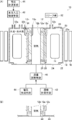
- FIG. 1A is a front view schematically showing the fuel cell according to the first embodiment of the present invention
- FIG. 1B is a partial modification thereof. It is a front view which shows typically the modification 1 of the fuel cell of the 1st Embodiment of this invention. It is a front view which shows typically the modification 2 of the fuel cell of the 1st Embodiment of this invention.
- FIG. 4A is a front view schematically showing a fuel cell according to a second embodiment of the present invention, and FIG. 4B is a partial modification thereof. It is a front view which shows typically the fuel cell of the 3rd Embodiment of this invention. It is a front view which shows typically the fuel cell of the 4th Embodiment of this invention.
- FIG. 7 is a plan view of the fuel cell shown in FIG. 6.
- FIG. 7 is a side view of the fuel cell shown in FIG. 6.
- FIG. 1A is a front view schematically showing the fuel cell according to the first embodiment of the present invention
- FIG. 1B is a partial modification thereof.
- the fuel cell 10 of the present invention includes a cylindrical electrode assembly 12, a negative electrode fuel material body 14, a heater 16, and a sealed container 20.
- the electrode assembly 12 includes a cylindrical airtight solid electrolyte body 12a, a positive electrode 12b (also referred to as an air electrode or a cathode), and a negative electrode 12c (also referred to as a fuel electrode or an anode), and includes a positive electrode lead wire 12p and a negative electrode lead wire. 12n.
- the solid electrolyte body 12a conducts oxygen ions
- the positive electrode 12b is formed on the inner surface of the solid electrolyte body 12a, reduces oxygen in the air to oxygen ions during discharge
- the negative electrode 12c is formed of the solid electrolyte body 12a. It is formed on the outer surface and oxidizes hydrogen gas to water vapor during discharge.
- FIG. 1 shows only one electrode composite 12, but a plurality of electrode composites may exist in one sealed container.
- the plurality of electrode composites are connected to each other in parallel or in series using the positive electrode lead wire 12p and the negative electrode lead wire 12n.
- the negative electrode fuel material body 14 reacts with water vapor to generate hydrogen gas, and becomes an oxide itself.
- the heater 16 is disposed on at least one of the outer side of the sealed container 20 and the inner side of the electrode assembly 12, and is for heating and maintaining the solid electrolyte body 12 a and the negative electrode fuel material body 14 at a predetermined temperature or higher.
- the sealed container 20 is disposed outside the electrode assembly 12, and includes an outer wall 22 that surrounds the electrode assembly 12, and seals the anode fuel material body 14 together with the electrode assembly 12.
- the heat insulator 18 can be disposed outside the heater 16 as necessary.
- the material of the heat insulator 18 is preferably a material having low thermal conductivity such as a foam material or a vacuum vessel.
- the electrode composite includes a type in which a negative electrode is formed inside a solid electrolyte body, a positive electrode formed outside (hereinafter referred to as an inner negative electrode type), a type in which a positive electrode is formed inside a solid electrolyte body, and a negative electrode is formed outside (solid inner positive electrode).
- an inner negative electrode type a type in which a positive electrode is formed inside a solid electrolyte body, and a negative electrode is formed outside
- solid inner positive electrode solid inner positive electrode
- the fuel cell using the inner negative electrode type electrode composite has a negative electrode fuel material body, a negative electrode, a solid electrolyte body, a positive electrode, an air area, a heater in this order from the inner side to the outer side, or a heater, a negative electrode fuel material body, a negative electrode, Since the solid electrolyte body, the positive electrode, and the air area are arranged in this order, the negative electrode fuel material body is first or second from the inside of the multiple cylindrical structure.
- the fuel cell 10 of the present invention uses an inner positive electrode type electrode composite, the air area, the positive electrode 12b, the solid electrolyte body 12a, the negative electrode 12c, the negative electrode fuel material body 14, Since the heaters 16 are arranged in this order, the anode fuel material body 14 is fifth from the inside of the multiple cylindrical structure.
- the volume of the anode fuel material body 14 of the fuel cell 10 of the present invention can be made larger than the volume of the anode fuel material body of the fuel cell using the inner anode type electrode composite. Therefore, by adopting such a configuration, the fuel cell 10 of the present invention can be configured to be simple and compact and have a sufficiently large battery capacity and energy density.
- the electrode assembly 12 may have an inner flow path in which air continuously rises from the lower end opening to the upper end opening so that air naturally convects in the electrode assembly 12. good.
- the air supplied to the inside of the electrode assembly 12 is heated and raised by the heater 16, and is discharged from the upper end opening of the electrode assembly 12, so that the air naturally flows from the lower end opening of the electrode assembly 12. Air flows into the.
- the fuel cell 10 further includes a pump (not shown) connected to the upper end opening or the lower end opening of the electrode assembly 12 so that air is forced to convection in the electrode assembly 12. You may have. In this case, air is forcibly supplied to the inside of the electrode assembly 12.
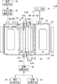
- the fuel cell 10 of the present invention may further include a temperature measuring means 42, a voltage measuring means 44, and a flow rate adjusting means 46.
- the temperature measuring unit 42 measures the air temperature inside the electrode assembly 12.
- the voltage measuring unit 44 measures an open voltage between the positive electrode 12b and the negative electrode 12c.
- the flow rate adjusting unit 46 is, for example, a flow rate adjusting valve, connected to one end of the electrode assembly 12, and at least one of the air temperature measured by the temperature measuring unit 42 and the open voltage measured by the voltage measuring unit 44. Based on the above, the flow rate of the air supplied to the inside of the electrode assembly 12 is adjusted.
- the flow rate adjusting means 46 increases the air flow rate inside the electrode assembly 12 when the open circuit voltage between the positive electrode 12b and the negative electrode 12c decreases.
- the flow rate adjusting valve is set so that the incremental amount increases as the air temperature increases, and the incremental amount decreases as the air temperature decreases. open. Accordingly, with such a configuration, the fuel cell 10 of the present invention can increase the stability of power supply to be equal to or higher than the conventional one.
- the fuel cell 10 of the present invention may further include water injection amount control means 48 connected to the water supply part 32a of the sealed container 20.
- the water injection amount control means 48 controls the amount of water injection into the sealed container 20 based on the open voltage measured by the voltage measurement means 44. That is, when the open voltage between the positive electrode 12b and the negative electrode 12c continues to decrease even after the air flow rate is adjusted by the flow rate adjusting unit 46, the water injection amount control unit 48 is placed in the sealed container 20 while watching the open voltage. A constant amount of water is injected intermittently. The amount of water injected per time is set based on the size and pressure resistance of the sealed container. The injected water is drained from the drainage part 32b of the sealed container 20 as necessary.
- pressure measuring means for measuring the internal pressure of the sealed container 20 is provided in place of the voltage measuring means 44, and the amount of water injected into the sealed container 20 is controlled based on the internal pressure measured by the pressure measuring means. It is difficult. That is, since hydrogen and water vapor are mixed in the sealed container, the pressure of only hydrogen cannot be measured even if the pressure measuring means is provided. Therefore, when the load of the fuel cell is changed, The hydrogen pressure cannot be kept at a predetermined value.
- the fuel cell 10 of the present invention injects water, the risk of complication and enlargement can be solved. Therefore, by adopting such a configuration, the fuel cell 10 of the present invention is simple and compact, and can increase the stability of power supply to the same level or higher than the conventional one.
- the fuel cell 10 may further include a relief valve 52 connected to the relief valve connection portion 32 c of the sealed container 20.
- the relief valve 52 is for keeping the internal pressure of the sealed container 20 below a predetermined value in order to keep safety.
- the relief valve 52 may be a general one, but it is more preferable that the relief valve 52 has an airtight structure like a rupture disk and breaks and releases the pressure when the pressure rises.
- the sealed container 20 may further include an end wall 24 and two cylindrical electrode supports 26.
- the end wall 24 is disposed at at least one end in the opening direction of the outer wall 22.
- Two cylindrical electrode supports 26 are joined to both ends of the electrode assembly 12.
- the material of the solid electrolyte body 12a is ceramics, and the material of the sealed container 20 including the electrode support 26 includes stainless steel.
- the outer periphery of the end wall 24 is joined to one end in the opening direction of the outer wall 22, and the inner circumference of the end wall 24 is joined to one of the electrode supports 26.
- At least one of the end wall 24 and the electrode support 26 has an elastic deformation part (not shown) for absorbing the difference in thermal expansion coefficient between the solid electrolyte body 12a and the outer wall 22.
- the end wall 24 is a stainless steel part having a shape like a diaphragm, and may have an elastic deformation portion between the outer periphery and the inner periphery.
- the electrode support 26 includes an elastic deformation portion such as rubber sandwiched between a stainless steel portion joined to the electrode assembly 12 and a stainless steel portion joined to the inner periphery of the end wall 24, and is integrated by adhesion or the like. May be used.
- the material of the solid electrolyte body 12a is ceramic and the material of the sealed container 20 is stainless steel
- heating with the heater 16 causes a difference in length due to the difference in thermal expansion coefficient between the solid electrolyte body 12a and the outer wall 22, and cracks are generated.
- the elastic deformation part absorbs the above difference in length, so that the risk of a decrease in airtightness can be solved. Therefore, with such a configuration, the fuel cell 10 of the present invention can have the same or better reliability than the conventional one.
- the sealed container 20 may further include a connection member 34 for preventing a short circuit of the negative electrode lead wire 12n and maintaining the hermeticity of the sealed container 20. That is, when the material of the sealed container 20 is stainless steel, the negative electrode lead wire 12n may be short-circuited to the sealed container 20.
- the connection member 34 is, for example, a Conax sealing ground manufactured by IBP Technology Corporation.
- the sealed container 20 may further include a cover plate 30 for replacing the anode fuel material body 14.
- the cover plate 30 is detachably fixed to the outer wall 22 or the end wall 24. That is, when the fuel cell 10 is used as a primary battery that performs only discharge, it is necessary to replace the negative electrode fuel material body 14 that has become an oxide with the original negative electrode fuel material body 14. Therefore, by adopting such a configuration, the fuel cell 10 of the present invention can improve the maintainability to be equal to or higher than the conventional one.
- the anode fuel material body 14 may be in the form of a pellet made of iron particles or iron powder and a shape-retaining material.
- the shape retaining material is made of a hardly sinterable material or a mixture thereof.
- the hardly sinterable material includes aluminum oxide, silicon dioxide, magnesium oxide, and zirconium oxide.
- At least a part of the surface of the negative electrode fuel substance body 14 is covered with a shape retention material, and the mass ratio of the shape retention material to the negative electrode fuel substance body 14 is 0.1% or more and 5% or less.
- the diameter of the pellet is, for example, 2 to 10 mm.
- the negative electrode fuel substance body 14 is always in an oxidized state when the partial pressure of the oxidizing gas is 1/1000 or more of the partial pressure of the reducing gas, and is coated with a shape retention material that is a metal oxide having a melting point of 1000 ° C. or higher. Preferably it is.
- a shape retention material that is a metal oxide having a melting point of 1000 ° C. or higher.
- the above-described shape retaining material has a particularly high melting point and a high sintering suppressing effect.
- the mass ratio of the shape-retaining material contained in the anode fuel substance body 14 is not particularly limited, but is preferably 0.1% or more and 5% or less in order not to suppress the oxidation-reduction rate too much.
- the positive electrode 12b and the negative electrode 12c repeat the reaction at the time of discharging and charging, respectively, and the negative electrode fuel material body 14 repeats the oxidation reaction and the reduction reaction. There is a need to do. Accordingly, with such a configuration, it is possible to eliminate the need to replace the anode fuel material body 14, and thus the fuel cell 10 of the present invention can have a maintenance property equal to or better than the conventional one.
- the positive electrode 12b oxidizes oxygen ions to oxygen during charging
- the negative electrode 12c reduces water vapor to hydrogen gas during charging
- the oxide of the negative electrode fuel material body 14 is reversible with hydrogen gas. It reacts to produce water vapor and may become the anode fuel material body 14 itself. That is, when the fuel cell 10 is used as a secondary battery, similarly, the positive electrode 12b and the negative electrode 12c repeat the reaction at the time of discharging and charging, respectively, and the negative electrode fuel material body 14 is oxidized and reduced. It is necessary to repeat the reaction. Accordingly, with such a configuration, it is possible to eliminate the need to replace the anode fuel material body 14, and thus the fuel cell 10 of the present invention can have a maintenance property equal to or better than the conventional one.
- the electrode composite body 12 is perpendicular to the opening direction. If the positive electrode 12 b and the negative electrode 12 c are exposed at both ends just by cutting, the positive electrode 12 b and the negative electrode 12 c are short-circuited via the electrode support 26.
- the positive electrode 12b and the negative electrode 12c in a predetermined range are peeled from both ends, and the solid electrolyte body 12a is coated on the surfaces of both ends of the positive electrode 12b.
- the negative electrode 12c in a predetermined range is peeled from both ends.
- the positive electrode 12b is exposed at both ends of the electrode assembly 12, the electrode support 26 and the positive electrode 12b are electrically connected. Therefore, when there are a plurality of electrode composites in one sealed container, the plurality of electrode composites are connected in parallel to each other.
- Ceramic bonding methods can be broadly classified into three methods: an intermediate material method, a direct bonding method, and a mechanical bonding method.
- the intermediate material method includes bonding using an organic adhesive or an inorganic adhesive, brazing using an inorganic material or a metal material, and pressure bonding.
- Direct bonding methods include solid phase bonding by diffusion and sintering, and welding by electron beam or laser.
- Mechanical joining methods include shrink fitting, bolting, and clamping.
- FIG. 1A shows an example in which a solid electrolyte body 12a made of a ceramic material and an electrode support body 26 made of a stainless steel material are joined using a pipe joint 28.
- FIG. 1B shows an example in which they are joined by an intermediate material method and a direct joining method, but these joining methods are not particularly limited as long as they can be reliably joined. It may be adopted.
- FIG. 2 is a front view schematically showing Modification 1 of the fuel cell according to the first embodiment of the present invention.
- the fuel cell 110 of the present invention includes a heat insulator 118 instead of the heat insulator 18, a point having a sealed container 120 instead of the sealed container 20, and an outer wall instead of the heater 16 and the outer wall 22. Since it has the same composition except having 122, the same referential mark is attached to the same component, and the explanation is omitted.
- the heat insulator 118 corresponds to the heat insulator 18, and the shape thereof is reduced in diameter, but the basic function is the same, and thus the description thereof is omitted.
- the heater may be configured integrally with the outer wall 122. That is, the fuel cell 110 includes a heat insulator 118 with a reduced outer diameter and an inner diameter while reducing the number of parts by incorporating a heater in the outer wall 122 of the sealed container 120. Therefore, by adopting such a configuration, the fuel cell 110 of the present invention can be configured to be simple and compact and have a sufficiently large battery capacity and energy density.
- FIG. 3 is a front view schematically showing Modification Example 2 of the fuel cell according to the first embodiment of the present invention.
- the fuel cell 210 of the present invention has a heater 216 having a lead wire 216 a and a lead wire 216 b instead of the heater 16 and a heater support 236 having a hole 236 a, and the heat insulator 18. Since it has the same configuration except that it has a heat insulator 218 instead of, the same reference numerals are assigned to the same components, and the description thereof is omitted.
- the heat insulator 218 corresponds to the heat insulator 18, and the shape thereof is reduced, but the basic function is the same, so the description thereof is omitted.
- the fuel cell 210 of the present invention uses an inner positive electrode type electrode composite
- the heater 216, air area, positive electrode 12 b, solid electrolyte body 12 a, negative electrode 12 c, and negative fuel material body 14 are arranged from the inner side to the outer side. Since the anode fuel material bodies 14 are arranged in order, the anode fuel material body 14 is sixth from the inside of the multiple cylindrical structure.
- the fuel cell 210 of the present invention may further include a heater support 236.
- the heater support 236 includes a hole 236 a that supports the heater 216 on the inside of the electrode assembly 12 and supplies air to the inside of the electrode assembly 12. That is, the fuel cell 210 includes a heat insulator 218 having a smaller outer diameter and inner diameter by supporting the heater 216 inside the electrode assembly 12.
- the desirable heating maintenance temperature of the solid electrolyte body 12 a is 800 ° C. or higher, and the desirable heating maintenance temperature of the negative electrode fuel material body 14 is 550 ° C. or higher.
- the solid electrolyte body 12 a is considerably more than the negative fuel material body 14. 1A and the fuel cell 110 of FIG. 2, when the heater is disposed outside the negative electrode fuel material body 14, the negative electrode fuel material body 14 close to the heater is 550 ° C. or more and far from the heater. Since the solid electrolyte body 12a must be heated and maintained at 800 ° C. or higher, energy efficiency is deteriorated. Further, since the anode fuel material body 14 is excessively heated, there is a possibility that the output is reduced due to aggregation.
- the fuel cell 210 of the present invention can have energy efficiency that is equal to or higher than that of the conventional one. Further, since the anode fuel material body 14 is not heated excessively, it is possible to avoid a decrease in output due to aggregation.
- FIG. 4A is a front view schematically showing a fuel cell according to a second embodiment of the present invention
- FIG. 4B is a partial modification thereof.
- the fuel cell 310 of the present invention is composed of a solid electrolyte body 312 a, a positive electrode 312 b, and a negative electrode 312 c instead of the electrode assembly 12, and an electrode having a positive electrode lead wire 312 p and a negative electrode lead wire 312 n.
- the sealed container 20, the outer wall 22, the end wall 24, the electrode support 26, and the pipe joint 28 are replaced with the sealed container 320, the outer wall 322, the end wall 324, the electrode support 326, and the pipe joint 328. Since it has the same composition except a point, the same referential mark is attached
- the electrode composite 312 has both ends in which the positive electrode 312b and the negative electrode 312c are exposed only by cutting the solid electrolyte body 312a, the positive electrode 312b, and the negative electrode 312c stacked in three layers at right angles to the opening direction.
- FIG. 4A shows an example in which the electrode assembly 312 and the electrode support 326 are joined using a pipe joint 328.
- FIG. 4B shows an example in which they are joined by the above-described intermediate material method and direct joining method, but these joining methods are not particularly limited as long as they can be reliably joined. A method may be adopted.
- the sealed container 320 may further include an end wall 324 and two cylindrical electrode supports 326.
- the end wall 324 is disposed at at least one end in the opening direction of the outer wall 322.
- Two cylindrical electrode supports 326 are joined to both ends of the electrode assembly 312.
- the material of the sealed container 320 including the solid electrolyte body 312a and the electrode support 326 is ceramic.
- the outer periphery of the end wall 324 is joined to one end in the opening direction of the outer wall 322, and the inner circumference of the end wall 324 is joined to one of the electrode supports 326.
- the anode fuel material body 14 of the fuel cell 310 of FIG. 4A is the fifth from the inside of the multi-tubular structure similarly to the fuel cell 10 of FIG. 1A described above, or similar to the fuel cell 210 of FIG. Since it becomes the sixth, the volume can be made larger than the volume of the negative electrode fuel material body of the fuel cell using the inner negative electrode type electrode composite. Therefore, by adopting such a configuration, the fuel cell 310 of the present invention can be configured to be simple and compact and have a sufficiently large battery capacity and energy density.
- FIG. 5 is a front view schematically showing a fuel cell according to a third embodiment of the present invention.
- the fuel cell 410 of the present invention is composed of a solid electrolyte body 412 a, a positive electrode 412 b, and a negative electrode 412 c instead of the electrode assembly 12, and an electrode having a positive electrode lead wire 412 p and a negative electrode lead wire 412 n.
- the point having the composite 412 Since it has the same configuration except for the point having the composite 412, the point having the sealed container 420, the outer wall 422, and the end wall 424 instead of the sealed container 20, the outer wall 22, and the end wall 24, Are denoted by the same reference numerals, and the description thereof is omitted.
- the electrode composite 412 has both ends in which the positive electrode 412b and the negative electrode 412c are exposed only by cutting the solid electrolyte body 412a, the positive electrode 412b, and the negative electrode 412c laminated in three layers at right angles to the opening direction.
- the sealed container 420 may further include an end wall 424.
- the end wall 424 is disposed at at least one end in the opening direction of the outer wall 422.
- the material of the solid electrolyte body 412a and the sealed container 420 is ceramic.
- the outer periphery of the end wall 424 is bonded to one end of the outer wall 422 in the opening direction, and the inner periphery of the end wall 424 is bonded to the electrode assembly 412.
- the negative electrode fuel material body 14 of the fuel cell 410 in FIG. 5 is the fifth from the inside of the multi-tubular structure as in the fuel cell 10 in FIG. 1A described above, or similar to the fuel cell 210 in FIG. Since it becomes the sixth, the volume can be made larger than the volume of the negative electrode fuel material body of the fuel cell using the inner negative electrode type electrode composite. Therefore, with such a configuration, the fuel cell 410 of the present invention can be configured to be simple and compact and have a sufficiently large battery capacity and energy density.
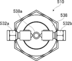
- FIG. 6 is a front view schematically showing a fuel cell according to a fourth embodiment of the present invention
- FIG. 7 is a plan view of the fuel cell shown in FIG. 6
- FIG. 8 is a fuel shown in FIG. It is a side view of a battery.
- the fuel cell 510 of the present invention has an electrode complex 512 composed of a solid electrolyte body 512 a, a positive electrode 512 b, and a negative electrode 512 c instead of the electrode complex 12, a sealed container 20, an outer wall 22, Since it has the same configuration except that it has an airtight container 520, an outer wall 522, an end wall 524, electrode supports 526a and 526b, a cap 538, and an exhaust pipe 538a instead of the end wall 24 and the electrode support 26,
- the same constituent elements are denoted by the same reference numerals, and the description thereof is omitted.
- the negative electrode fuel material body 514, the heater 516, and the heat insulator 518 correspond to the negative electrode fuel material body 14, the heater 16, and the heat insulator 18, respectively. Since it is the same, the description thereof is omitted. 7 and 8 show a state in which the heater 516 and the heat insulator 518 are removed from the fuel cell 510. FIG.
- the electrode assembly 512 includes a solid electrolyte body 512a (not shown), a positive electrode 512b (not shown), and a negative electrode 512c (not shown) instead of the electrode composite 12, and an electrode support 526a to be joined.
- the state of both ends differs depending on the material of 526b.
- the sealed container 520 may further include an end wall 524, two cylindrical electrode supports 526a and 526b, and a cap 538 for replacing the negative electrode fuel material body 514.
- the end wall 524 is disposed at at least one end in the opening direction of the outer wall 522.
- Two cylindrical electrode supports 526 a and 526 b are joined to both ends of the electrode assembly 512.
- the outer periphery of the end wall 524 abuts against the cap 538, and the cap 538 is detachably screwed to one end in the opening direction of the outer wall 522, whereby one end in the opening direction of the outer wall 522 is interposed via the cap 538.
- the cap 538 includes a water supply portion 532a connected to the water injection amount control means 48, a drainage portion 532b from which the injected water is drained as necessary, and an exhaust pipe 538a that exhausts the air inside the electrode assembly 512. And comprising.
- the negative electrode fuel material body 514 of the fuel cell 510 of FIG. 6 is fifth from the inside of the multi-tubular structure similarly to the fuel cell 10 of FIG. 1A described above, or similar to the fuel cell 210 of FIG. Since it becomes the sixth, the volume can be made larger than the volume of the negative electrode fuel material body of the fuel cell using the inner negative electrode type electrode composite. Further, when the fuel cell 510 is used as a primary battery that performs only discharge, it is necessary to replace the negative electrode fuel material body 514 that has become an oxide with the original negative electrode fuel material body 514. Therefore, by adopting such a configuration, the fuel cell 510 of the present invention can be configured to be simple and compact and have a sufficiently large battery capacity and energy density, and at the same time, has better maintenance than the conventional one. Can be.
- the material of the solid electrolyte body 512a may be ceramics, and the material of the sealed container 520 may be stainless steel.
- at least one of the end wall 524 and the electrode supports 526a and 526b has an elastic deformation portion (not shown) for absorbing the difference in thermal expansion coefficient between the solid electrolyte body 512a and the outer wall 522.
- the end wall 524 is a stainless steel part having a shape like a diaphragm, and may have an elastic deformation portion between the outer periphery and the inner periphery.
- the electrode support 526b is formed by sandwiching an elastically deforming portion such as rubber between a stainless steel portion joined to the electrode composite 512 and a stainless steel portion joined to the inner periphery of the end wall 524, and is integrated by adhesion or the like. May be used.
- the material of the solid electrolyte body 512a is ceramic and the material of the sealed container 520 is stainless steel
- heating with the heater 516 causes a difference in length due to the difference in thermal expansion coefficient between the solid electrolyte body 512a and the outer wall 522, resulting in cracks.
- the elastic deformation part absorbs the difference in length, so that the risk of a decrease in airtightness can be solved. Therefore, with such a configuration, the fuel cell 510 of the present invention can have the same or better reliability than the conventional one.
- the method of joining the electrode assembly 512 and the electrode supports 526a and 526b is the same as that of the fuel cell 10 shown in FIGS. 1A and 1B described above, and a description thereof will be omitted.
- the material of the sealed container 520 including the solid electrolyte body 512a and the electrode support bodies 526a and 526b may be ceramics.
- the joining method of the electrode assembly 512 and the electrode supports 526a and 526b is the same as that of the fuel cell 310 of FIGS. 4A and 4B described above, and therefore the description thereof is omitted.
- the fuel cell of the present invention is basically configured as described above.
- the fuel cell according to the present invention is simple and compact, and has an effect that the battery capacity and the energy density can be sufficiently large.
- the power supply stability is higher than that of the conventional one, and the reliability and maintainability. It is also industrially useful because it has the effect of improving energy efficiency.
Landscapes
- Chemical & Material Sciences (AREA)
- Chemical Kinetics & Catalysis (AREA)
- Electrochemistry (AREA)
- General Chemical & Material Sciences (AREA)
- Life Sciences & Earth Sciences (AREA)
- Engineering & Computer Science (AREA)
- Manufacturing & Machinery (AREA)
- Sustainable Development (AREA)
- Sustainable Energy (AREA)
- Fuel Cell (AREA)
- Composite Materials (AREA)
Abstract
Description
また、本発明の他の目的は、上記目的に加え、従来と同等以上に電力供給の安定性が高く、信頼性とメンテナンス性とエネルギー効率が良好な燃料電池を提供することにある。 The present invention has been made in view of such conventional problems, and an object of the present invention is simple and compact by incorporating a hydrogen generator, and has a sufficiently large battery capacity and energy density. It is to provide a fuel cell.
In addition to the above object, another object of the present invention is to provide a fuel cell that has high power supply stability equal to or higher than that of the prior art, and that has good reliability, maintainability, and energy efficiency.
さらに、電極複合体の内側に強制的に空気が供給されるように、電極複合体の上端開口または下端開口に接続されたポンプを有するのが好ましい。
さらに、電極複合体の内側の空気温度を計測する温度計測手段と、正極と負極との間の開放電圧を計測する電圧計測手段と、電極複合体の一方の端に接続され、温度計測手段によって計測された空気温度および電圧計測手段によって計測された開放電圧の少なくとも一方に基づいて電極複合体の内側に供給される空気の流量を調整する流量調整手段と、を有するのが好ましい。 Here, in the above, the air supplied to the inside of the electrode assembly is heated and raised by the heater, and is discharged from the upper end opening of the electrode assembly, so that the air naturally flows from the lower end opening of the electrode assembly. It is preferable that the electrode assembly has an inner flow path in which air continuously rises from the lower end opening to the upper end opening so that the air flows.
Furthermore, it is preferable to have a pump connected to the upper end opening or the lower end opening of the electrode composite so that air is forcibly supplied to the inside of the electrode composite.
Furthermore, a temperature measuring means for measuring the air temperature inside the electrode composite, a voltage measuring means for measuring an open voltage between the positive electrode and the negative electrode, and one end of the electrode composite are connected to each other by the temperature measuring means. It is preferable to have a flow rate adjusting unit that adjusts the flow rate of air supplied to the inside of the electrode assembly based on at least one of the measured air temperature and the open circuit voltage measured by the voltage measuring unit.
密閉容器は、さらに、外壁の開口方向の少なくとも一方の端に配置された端壁と、電極複合体の両端のそれぞれに接合される筒状の2つの電極支持体と、を備え、固体電解質体の材料は、セラミックスであり、密閉容器の材料は、ステンレスを含み、端壁の外周は、外壁の開口方向の一方の端に接合され、端壁の内周は、電極支持体の一方に接合され、端壁および電極支持体の少なくとも一方は、固体電解質体および外壁の熱膨張率の違いを吸収するための弾性変形部を有するのが好ましい。
密閉容器は、さらに、負極のリード線の短絡を防ぎかつ密閉容器の気密性を保つための接続部材を有するのが好ましい。 Furthermore, it is preferable to have water injection amount control means for controlling the amount of water injected into the sealed container based on the open voltage measured by the voltage measurement means.
The hermetic container further includes an end wall disposed at at least one end in the opening direction of the outer wall, and two cylindrical electrode supports bonded to both ends of the electrode composite, and a solid electrolyte body The material of the airtight container includes stainless steel, the outer periphery of the end wall is bonded to one end in the opening direction of the outer wall, and the inner periphery of the end wall is bonded to one of the electrode supports. In addition, it is preferable that at least one of the end wall and the electrode support has an elastic deformation portion for absorbing a difference in thermal expansion coefficient between the solid electrolyte body and the outer wall.
The sealed container preferably further has a connecting member for preventing a short circuit of the negative lead wire and maintaining the hermeticity of the sealed container.
密閉容器は、さらに、外壁の開口方向の少なくとも一方の端に配置された端壁を備え、固体電解質体および密閉容器の材料は、セラミックスであり、端壁の外周は、外壁の開口方向の一方の端に接合され、端壁の内周は、電極複合体に接合されるのが好ましい。
密閉容器は、さらに、負極燃料物質体を入れ換えるためのカバープレートを備え、カバープレートは、外壁または端壁に着脱自在に固定されるのが好ましい。 The hermetic container further includes an end wall disposed at at least one end in the opening direction of the outer wall, and two cylindrical electrode supports bonded to both ends of the electrode composite, and a solid electrolyte body The material of the closed container is ceramic, and the outer periphery of the end wall is preferably bonded to one end in the opening direction of the outer wall, and the inner periphery of the end wall is preferably bonded to one of the electrode supports.
The sealed container further includes an end wall disposed at at least one end in the opening direction of the outer wall, the material of the solid electrolyte body and the sealed container is ceramic, and the outer periphery of the end wall is one of the opening direction of the outer wall. The inner periphery of the end wall is preferably bonded to the electrode assembly.
The sealed container further includes a cover plate for replacing the negative electrode fuel material body, and the cover plate is preferably detachably fixed to the outer wall or the end wall.
固体電解質体の材料は、セラミックスであり、密閉容器の材料は、ステンレスであり、端壁および電極支持体の少なくとも一方は、固体電解質体および外壁の熱膨張率の違いを吸収するための弾性変形部を有するのが好ましい。
固体電解質体および密閉容器の材料は、セラミックスであるのが好ましい。
ヒータは、外壁と一体的に構成されるのが好ましい。 The sealed container further exchanges the negative electrode fuel material body with the end wall disposed at least at one end in the opening direction of the outer wall, the two cylindrical electrode supports bonded to both ends of the electrode assembly, respectively. The outer periphery of the end wall is in contact with the cap and is detachably screwed to one end in the opening direction of the outer wall, thereby allowing the outer wall in the opening direction of the outer wall to pass through the cap. It is preferable that one end is joined and the inner periphery of the end wall is in contact with one end surface of the electrode support.
The material of the solid electrolyte body is ceramics, the material of the sealed container is stainless steel, and at least one of the end wall and the electrode support is elastically deformed to absorb the difference in thermal expansion coefficient between the solid electrolyte body and the outer wall. It is preferable to have a part.
The material of the solid electrolyte body and the sealed container is preferably ceramics.
The heater is preferably configured integrally with the outer wall.
負極燃料物質体は、鉄粒子もしくは鉄粉末と、酸化アルミニウム、二酸化ケイ素、酸化マグネシウム、酸化ジルコニウムを含む難焼結性材料、またはこれらの混合物からなる形態保持材料と、からなるペレット状のものであり、負極燃料物質体の表面の少なくとも一部は、形態保持材料で覆われており、負極燃料物質体に対する形態保持材料の質量比は、0.1%以上5%以下であるのが好ましい。
正極は、充電時に酸素イオンを酸素に酸化し、負極は、充電時に水蒸気を水素ガスに還元し、負極燃料物質体の酸化物は、水素ガスと可逆的に反応して水蒸気を生成し、自らは負極燃料物質体となるのが好ましい。 Furthermore, it is preferable that a heater support for supporting the heater inside the electrode composite is provided, and the heater support includes a hole for supplying air to the inside of the electrode composite.
The negative electrode fuel substance body is in the form of a pellet made of iron particles or iron powder and a non-sinterable material containing aluminum oxide, silicon dioxide, magnesium oxide, zirconium oxide, or a shape-retaining material made of a mixture thereof. In addition, it is preferable that at least a part of the surface of the negative electrode fuel substance body is covered with a shape holding material, and the mass ratio of the shape holding material to the negative electrode fuel substance body is 0.1% or more and 5% or less.
The positive electrode oxidizes oxygen ions to oxygen during charging, the negative electrode reduces water vapor to hydrogen gas during charging, and the oxide of the negative electrode fuel material reacts reversibly with hydrogen gas to produce water vapor. Is preferably a negative electrode fuel material.
また、本発明によれば、上記効果に加え、従来と同等以上に電力供給の安定性を高く、信頼性とメンテナンス性とエネルギー効率を良好にすることができる。 According to the present invention, a simple and compact configuration with a sufficiently large battery capacity and energy density can be achieved.
Further, according to the present invention, in addition to the above effects, the stability of power supply is higher than that of the conventional one, and the reliability, maintainability, and energy efficiency can be improved.
まず、本発明の第1の実施形態の燃料電池について説明する。図1Aは、本発明の第1の実施形態の燃料電池を模式的に示す正面図であり、図1Bは、その一部の変形例である。 Hereinafter, a fuel cell of the present invention will be described in detail based on preferred embodiments shown in the accompanying drawings.
First, the fuel cell according to the first embodiment of the present invention will be described. FIG. 1A is a front view schematically showing the fuel cell according to the first embodiment of the present invention, and FIG. 1B is a partial modification thereof.
本発明の燃料電池10では、負極燃料物質体14は、鉄粒子もしくは鉄粉末と形態保持材料とからなるペレット状のものでも良い。形態保持材料は、難焼結性材料またはその混合物からなる。難焼結性材料は、酸化アルミニウム、二酸化ケイ素、酸化マグネシウム、酸化ジルコニウムを含む。負極燃料物質体14の表面の少なくとも一部は、形態保持材料で覆われ、負極燃料物質体14に対する形態保持材料の質量比は、0.1%以上5%以下である。ペレットの直径は、例えば、2~10mmである。 Next, the relationship between the material of the negative electrode
In the
固体電解質体12aと正極12bと負極12cが三層に積層された電極複合体12と、材料がステンレスの電極支持体26と、を接合する場合には、電極複合体12を開口方向と直角に切断しただけで両端に正極12bと負極12cが露出した状態だと、電極支持体26を介して正極12bと負極12cが短絡する。 Next, the state of both ends of the
When joining the electrode
セラミックスの接合方法は、大別すると、中間材法と直接的接合法と機械的接合法の3つがある。中間材法には、有機接着剤や無機接着剤を使用した接着、無機材料や金属材料を使用したろう付けがあり、圧着もある。直接的接合法には、拡散や焼結による固相接合、電子ビームやレーザによる溶接がある。機械的接合法には、焼ばめ、ボルト締め、クランプ締めなどがある。 Next, a ceramic bonding method will be described.
Ceramic bonding methods can be broadly classified into three methods: an intermediate material method, a direct bonding method, and a mechanical bonding method. The intermediate material method includes bonding using an organic adhesive or an inorganic adhesive, brazing using an inorganic material or a metal material, and pressure bonding. Direct bonding methods include solid phase bonding by diffusion and sintering, and welding by electron beam or laser. Mechanical joining methods include shrink fitting, bolting, and clamping.
本発明の燃料電池110は、燃料電池10と比較すると、断熱体18の代わりに断熱体118を有する点、密閉容器20の代わりに密閉容器120を有する点、ヒータ16および外壁22の代わりに外壁122を有する点以外は同一の構成を有するものであるので、同一の構成要素には、同一の参照符号を付し、その説明を省略する。また、断熱体118は、断熱体18に対応するものであり、その形状は小径化しているが、基本的な機能は同一であるので、その説明を省略する。 Next, Modification 1 of the fuel cell according to the first embodiment of the present invention will be described. FIG. 2 is a front view schematically showing Modification 1 of the fuel cell according to the first embodiment of the present invention.
Compared with the
本発明の燃料電池210は、燃料電池10と比較すると、ヒータ16の代わりにリード線216aとリード線216bとを備えたヒータ216および孔236aを備えたヒータ支持体236を有する点、断熱体18の代わりに断熱体218を有する点以外は同一の構成を有するものであるので、同一の構成要素には、同一の参照符号を付し、その説明を省略する。また、断熱体218は、断熱体18に対応するものであり、その形状は小径化しているが、基本的な機能は同一であるので、その説明を省略する。 Next, Modification Example 2 of the fuel cell according to the first embodiment of the present invention will be described. FIG. 3 is a front view schematically showing Modification Example 2 of the fuel cell according to the first embodiment of the present invention.
Compared with the
本発明の燃料電池310は、燃料電池10と比較すると、電極複合体12の代わりに固体電解質体312aと正極312bと負極312cとから成りかつ正極リード線312pと負極リード線312nとを備えた電極複合体312を有する点、密閉容器20、外壁22、端壁24、電極支持体26、管継手28の代わりに密閉容器320、外壁322、端壁324、電極支持体326、管継手328を有する点以外は同一の構成を有するものであるので、同一の構成要素には、同一の参照符号を付し、その説明を省略する。 Next, a fuel cell according to a second embodiment of the present invention will be described. FIG. 4A is a front view schematically showing a fuel cell according to a second embodiment of the present invention, and FIG. 4B is a partial modification thereof.
Compared with the
本発明の燃料電池410は、燃料電池10と比較すると、電極複合体12の代わりに固体電解質体412aと正極412bと負極412cとから成りかつ正極リード線412pと負極リード線412nとを備えた電極複合体412を有する点、密閉容器20、外壁22、端壁24の代わりに密閉容器420、外壁422、端壁424を有する点以外は同一の構成を有するものであるので、同一の構成要素には、同一の参照符号を付し、その説明を省略する。 Next, a fuel cell according to a third embodiment of the present invention will be described. FIG. 5 is a front view schematically showing a fuel cell according to a third embodiment of the present invention.
Compared with the
本発明の燃料電池510は、燃料電池10と比較すると、電極複合体12の代わりに固体電解質体512aと正極512bと負極512cとから成る電極複合体512を有する点、密閉容器20、外壁22、端壁24、電極支持体26の代わりに密閉容器520、外壁522、端壁524、電極支持体526a、526b、キャップ538、排気管538aを有する点以外は同一の構成を有するものであるので、同一の構成要素には、同一の参照符号を付し、その説明を省略する。また、負極燃料物質体514、ヒータ516、断熱体518は、負極燃料物質体14、ヒータ16、断熱体18にそれぞれ対応するものであり、その形状は相違しているが、基本的な機能は同一であるので、その説明を省略する。なお、図7、図8は、燃料電池510からヒータ516、断熱体518が取り外された状態を示している。 Next, a fuel cell according to a fourth embodiment of the present invention will be described. 6 is a front view schematically showing a fuel cell according to a fourth embodiment of the present invention, FIG. 7 is a plan view of the fuel cell shown in FIG. 6, and FIG. 8 is a fuel shown in FIG. It is a side view of a battery.
Compared with the
本発明の燃料電池は、基本的に以上のように構成される。 In the
The fuel cell of the present invention is basically configured as described above.
12、312、412、512 電極複合体(SOFCチューブ)
12a、312a、412a 固体電解質体
12b、312b、412b 正極
12c、312c、412c 負極
12p、312p、412p 正極リード線
12n、312n、412n 負極リード線
14、514 負極燃料物質体
16、216、516 ヒータ
18、118、218、518 断熱体
20、120、320、420、520 密閉容器
22、122、322、422、522 外壁
24、324、424、524 端壁
26、326、526a、526b 電極支持体
28、328 管継手
30 カバープレート
32a、532a 給水部
32b、532b 排水部
32c リリーフ弁接続部
34 接続部材
42 温度計測手段
44 電圧計測手段
46 流量調整手段
48 水注入量制御手段
52 リリーフ弁
216a、216b リード線
236 ヒータ支持体
236a 孔
538 キャップ
538a 排気管 10, 110, 210, 310, 410, 510
12a, 312a, 412a
Claims (17)
- 酸素イオンを伝導する筒状の気密性の固体電解質体、前記固体電解質体の内側の面に形成され、放電時に空気中の酸素を酸素イオンに還元する正極、および前記固体電解質体の外側の面に形成され、放電時に水素ガスを水蒸気に酸化する負極から成る筒状の電極複合体と、
前記水蒸気と反応して前記水素ガスを生成し、自らは酸化物となる負極燃料物質体と、
前記電極複合体の外側に配置され、前記電極複合体の周囲を取り囲む外壁を備え、前記電極複合体と共に、前記負極燃料物質体を内部に密閉する密閉容器と、
前記密閉容器の外側および前記電極複合体の内側の少なくとも一方に配置され、前記固体電解質体および前記負極燃料物質体を所定の温度以上に加熱維持するためのヒータと、を有する燃料電池。 A cylindrical airtight solid electrolyte body that conducts oxygen ions, a positive electrode that is formed on the inner surface of the solid electrolyte body and reduces oxygen in the air to oxygen ions during discharge, and an outer surface of the solid electrolyte body A cylindrical electrode composite formed of a negative electrode that is formed into a negative electrode that oxidizes hydrogen gas into water vapor during discharge;
A negative electrode fuel material body that reacts with the water vapor to produce the hydrogen gas, which itself becomes an oxide;
A sealed container that is disposed outside the electrode composite and includes an outer wall that surrounds the periphery of the electrode composite;
A fuel cell, comprising: a heater disposed on at least one of the outer side of the hermetic container and the inner side of the electrode assembly for heating and maintaining the solid electrolyte body and the negative electrode fuel material body at a predetermined temperature or higher. - 前記電極複合体の内側に供給された空気は、前記ヒータによって加熱されて上昇し、前記電極複合体の上端開口から排出されることによって、前記電極複合体の下端開口から自然に空気が流入するように、前記電極複合体は、前記下端開口から前記上端開口まで空気が連続的に上昇する内側流路を有する請求項1に記載の燃料電池。 The air supplied to the inside of the electrode assembly is heated and raised by the heater, and is discharged from the upper end opening of the electrode assembly, so that air naturally flows from the lower end opening of the electrode assembly. The fuel cell according to claim 1, wherein the electrode assembly has an inner flow path in which air continuously rises from the lower end opening to the upper end opening.
- さらに、前記電極複合体の内側に強制的に空気が供給されるように、前記電極複合体の上端開口または下端開口に接続されたポンプを有する請求項1に記載の燃料電池。 The fuel cell according to claim 1, further comprising a pump connected to an upper end opening or a lower end opening of the electrode assembly so that air is forcibly supplied to the inside of the electrode assembly.
- さらに、前記電極複合体の内側の空気温度を計測する温度計測手段と、前記正極と前記負極との間の開放電圧を計測する電圧計測手段と、前記電極複合体の一方の端に接続され、前記温度計測手段によって計測された空気温度および前記電圧計測手段によって計測された開放電圧の少なくとも一方に基づいて前記電極複合体の内側に供給される空気の流量を調整する流量調整手段と、を有する請求項1~3のいずれか1項に記載の燃料電池。 Furthermore, a temperature measuring means for measuring the air temperature inside the electrode composite, a voltage measuring means for measuring an open voltage between the positive electrode and the negative electrode, and one end of the electrode composite are connected, Flow rate adjusting means for adjusting the flow rate of air supplied to the inside of the electrode assembly based on at least one of the air temperature measured by the temperature measuring means and the open circuit voltage measured by the voltage measuring means. The fuel cell according to any one of claims 1 to 3.
- さらに、前記電圧計測手段によって計測された開放電圧に基づいて前記密閉容器への水の注入量を制御する水注入量制御手段を有する請求項4に記載の燃料電池。 5. The fuel cell according to claim 4, further comprising water injection amount control means for controlling the amount of water injected into the sealed container based on the open voltage measured by the voltage measurement means.
- 前記密閉容器は、さらに、前記外壁の開口方向の少なくとも一方の端に配置された端壁と、前記電極複合体の両端のそれぞれに接合される筒状の2つの電極支持体と、を備え、
前記固体電解質体の材料は、セラミックスであり、前記密閉容器の材料は、ステンレスを含み、
前記端壁の外周は、前記外壁の開口方向の一方の端に接合され、前記端壁の内周は、前記電極支持体の一方に接合され、
前記端壁および前記電極支持体の少なくとも一方は、前記固体電解質体および前記外壁の熱膨張率の違いを吸収するための弾性変形部を有する請求項1~5のいずれか1項に記載の燃料電池。 The sealed container further includes an end wall disposed at at least one end in the opening direction of the outer wall, and two cylindrical electrode supports bonded to both ends of the electrode complex,
The material of the solid electrolyte body is ceramics, and the material of the sealed container includes stainless steel,
The outer periphery of the end wall is bonded to one end in the opening direction of the outer wall, and the inner periphery of the end wall is bonded to one of the electrode supports,
The fuel according to any one of claims 1 to 5, wherein at least one of the end wall and the electrode support has an elastically deformable portion for absorbing a difference in thermal expansion coefficient between the solid electrolyte body and the outer wall. battery. - 前記密閉容器は、さらに、前記負極のリード線の短絡を防ぎかつ前記密閉容器の気密性を保つための接続部材を有する請求項6に記載の燃料電池。 The fuel cell according to claim 6, wherein the sealed container further has a connecting member for preventing a short circuit of the lead wire of the negative electrode and maintaining the hermeticity of the sealed container.
- 前記密閉容器は、さらに、前記外壁の開口方向の少なくとも一方の端に配置された端壁と、前記電極複合体の両端のそれぞれに接合される筒状の2つの電極支持体と、を備え、
前記固体電解質体および前記密閉容器の材料は、セラミックスであり、
前記端壁の外周は、前記外壁の開口方向の一方の端に接合され、前記端壁の内周は、前記電極支持体の一方に接合される請求項1~5のいずれか1項に記載の燃料電池。 The sealed container further includes an end wall disposed at at least one end in the opening direction of the outer wall, and two cylindrical electrode supports bonded to both ends of the electrode complex,
The material of the solid electrolyte body and the sealed container is ceramics,
The outer periphery of the end wall is bonded to one end in the opening direction of the outer wall, and the inner periphery of the end wall is bonded to one of the electrode supports. Fuel cell. - 前記密閉容器は、さらに、前記外壁の開口方向の少なくとも一方の端に配置された端壁を備え、
前記固体電解質体および前記密閉容器の材料は、セラミックスであり、
前記端壁の外周は、前記外壁の開口方向の一方の端に接合され、前記端壁の内周は、前記電極複合体に接合される請求項1~5のいずれか1項に記載の燃料電池。 The sealed container further includes an end wall disposed at at least one end in the opening direction of the outer wall,
The material of the solid electrolyte body and the sealed container is ceramics,
The fuel according to any one of claims 1 to 5, wherein an outer periphery of the end wall is bonded to one end in an opening direction of the outer wall, and an inner periphery of the end wall is bonded to the electrode assembly. battery. - 前記密閉容器は、さらに、前記負極燃料物質体を入れ換えるためのカバープレートを備え、
前記カバープレートは、前記外壁または前記端壁に着脱自在に固定される請求項6~9のいずれか1項に記載の燃料電池。 The sealed container further includes a cover plate for replacing the negative electrode fuel material body,
10. The fuel cell according to claim 6, wherein the cover plate is detachably fixed to the outer wall or the end wall. - 前記密閉容器は、さらに、前記外壁の開口方向の少なくとも一方の端に配置された端壁と、前記電極複合体の両端のそれぞれに接合される筒状の2つの電極支持体と、前記負極燃料物質体を入れ換えるためのキャップと、を備え、
前記端壁の外周は、前記キャップに当接し、前記外壁の開口方向の一方の端に対して前記キャップを着脱自在に螺合することによって、前記キャップを介して前記外壁の開口方向の一方の端に接合され、前記端壁の内周は、前記電極支持体の一方の端面に当接する請求項1~5のいずれか1項に記載の燃料電池。 The sealed container further includes an end wall disposed at at least one end in the opening direction of the outer wall, two cylindrical electrode supports bonded to both ends of the electrode assembly, and the negative electrode fuel. A cap for replacing the substance body,
The outer periphery of the end wall abuts on the cap, and the cap is detachably screwed to one end in the opening direction of the outer wall, whereby one end in the opening direction of the outer wall is interposed through the cap. The fuel cell according to any one of claims 1 to 5, wherein the fuel cell is joined to an end, and an inner periphery of the end wall is in contact with one end face of the electrode support. - 前記固体電解質体の材料は、セラミックスであり、前記密閉容器の材料は、ステンレスであり、
前記端壁および前記電極支持体の少なくとも一方は、前記固体電解質体および前記外壁の熱膨張率の違いを吸収するための弾性変形部を有する請求項11に記載の燃料電池。 The material of the solid electrolyte body is ceramics, and the material of the sealed container is stainless steel,
12. The fuel cell according to claim 11, wherein at least one of the end wall and the electrode support has an elastic deformation portion for absorbing a difference in coefficient of thermal expansion between the solid electrolyte body and the outer wall. - 前記固体電解質体および前記密閉容器の材料は、セラミックスである請求項11に記載の燃料電池。 The fuel cell according to claim 11, wherein the material of the solid electrolyte body and the sealed container is ceramics.
- 前記ヒータは、前記外壁と一体的に構成される請求項1~13のいずれか1項に記載の燃料電池。 The fuel cell according to any one of claims 1 to 13, wherein the heater is configured integrally with the outer wall.
- さらに、前記ヒータを前記電極複合体の内側に支持するヒータ支持体を備え、
前記ヒータ支持体は、前記電極複合体の内側に空気を供給するための孔を備える請求項1~13のいずれか1項に記載の燃料電池。 Furthermore, a heater support that supports the heater inside the electrode composite is provided,
The fuel cell according to any one of claims 1 to 13, wherein the heater support includes a hole for supplying air to the inside of the electrode assembly. - 前記負極燃料物質体は、鉄粒子もしくは鉄粉末と、酸化アルミニウム、二酸化ケイ素、酸化マグネシウム、酸化ジルコニウムを含む難焼結性材料、またはこれらの混合物からなる形態保持材料と、からなるペレット状のものであり、
前記負極燃料物質体の表面の少なくとも一部は、前記形態保持材料で覆われており、
前記負極燃料物質体に対する前記形態保持材料の質量比は、0.1%以上5%以下である請求項1~15のいずれか1項に記載の燃料電池。 The negative electrode fuel substance body is in the form of a pellet made of iron particles or iron powder and a non-sinterable material containing aluminum oxide, silicon dioxide, magnesium oxide, zirconium oxide, or a shape-retaining material made of a mixture thereof. And
At least a part of the surface of the negative electrode fuel substance body is covered with the shape retention material,
The fuel cell according to any one of claims 1 to 15, wherein a mass ratio of the shape maintaining material to the negative electrode fuel substance body is 0.1% or more and 5% or less. - 前記正極は、充電時に酸素イオンを酸素に酸化し、
前記負極は、充電時に前記水蒸気を前記水素ガスに還元し、
前記負極燃料物質体の酸化物は、前記水素ガスと可逆的に反応して前記水蒸気を生成し、自らは負極燃料物質体となる請求項1~16のいずれか1項に記載の燃料電池。 The positive electrode oxidizes oxygen ions to oxygen during charging,
The negative electrode reduces the water vapor to the hydrogen gas during charging,
The fuel cell according to any one of claims 1 to 16, wherein the oxide of the negative electrode fuel material reacts reversibly with the hydrogen gas to generate the water vapor, and becomes an anode fuel material itself.
Priority Applications (4)
| Application Number | Priority Date | Filing Date | Title |
|---|---|---|---|
| JP2017565669A JP6767399B2 (en) | 2016-02-04 | 2017-02-03 | Fuel cell |
| US16/075,392 US20190036145A1 (en) | 2016-02-04 | 2017-02-03 | Fuel cell |
| EP17747602.5A EP3413385A4 (en) | 2016-02-04 | 2017-02-03 | Fuel cell |
| CN201780009616.7A CN108604689B (en) | 2016-02-04 | 2017-02-03 | Fuel cell |
Applications Claiming Priority (2)
| Application Number | Priority Date | Filing Date | Title |
|---|---|---|---|
| JP2016020186 | 2016-02-04 | ||
| JP2016-020186 | 2016-02-04 |
Publications (1)
| Publication Number | Publication Date |
|---|---|
| WO2017135451A1 true WO2017135451A1 (en) | 2017-08-10 |
Family
ID=59499706
Family Applications (1)
| Application Number | Title | Priority Date | Filing Date |
|---|---|---|---|
| PCT/JP2017/004103 WO2017135451A1 (en) | 2016-02-04 | 2017-02-03 | Fuel cell |
Country Status (5)
| Country | Link |
|---|---|
| US (1) | US20190036145A1 (en) |
| EP (1) | EP3413385A4 (en) |
| JP (1) | JP6767399B2 (en) |
| CN (1) | CN108604689B (en) |
| WO (1) | WO2017135451A1 (en) |
Cited By (1)
| Publication number | Priority date | Publication date | Assignee | Title |
|---|---|---|---|---|
| JP2020061356A (en) * | 2018-10-09 | 2020-04-16 | 日本碍子株式会社 | Fuel cell device |
Families Citing this family (4)
| Publication number | Priority date | Publication date | Assignee | Title |
|---|---|---|---|---|
| CN113994510B (en) * | 2019-07-30 | 2024-01-30 | 康奈克斯系统株式会社 | Fuel cell system, nuclear fusion power generation system, and sealed container constituting the same |
| CN112751068A (en) * | 2020-01-20 | 2021-05-04 | 熵零技术逻辑工程院集团股份有限公司 | Fuel cell |
| CN113764706B (en) * | 2020-12-31 | 2023-03-21 | 厦门大学 | Secondary fuel cell with active circulation system |
| JP7285608B1 (en) * | 2021-10-25 | 2023-06-02 | Connexx Systems株式会社 | Composite battery and composite battery system including the same |
Citations (8)
| Publication number | Priority date | Publication date | Assignee | Title |
|---|---|---|---|---|
| JP2004281393A (en) | 2003-02-25 | 2004-10-07 | Riken Corp | Fuel cell power generation system |
| WO2011089811A1 (en) * | 2010-01-22 | 2011-07-28 | コニカミノルタホールディングス株式会社 | Fuel cell system |
| JP2011222290A (en) * | 2010-04-09 | 2011-11-04 | Konica Minolta Holdings Inc | Fuel cell |
| JP5188236B2 (en) | 2008-03-28 | 2013-04-24 | 東邦瓦斯株式会社 | Gas supply / discharge manifold and solid oxide fuel cell bundle |
| JP5210450B1 (en) * | 2012-11-07 | 2013-06-12 | 直芳 可知 | Fuel cell and fuel cell system |
| WO2013084733A1 (en) * | 2011-12-06 | 2013-06-13 | コニカミノルタ株式会社 | Fuel generator and secondary battery-type fuel cell system equipped with same |
| JP2014139894A (en) * | 2013-01-21 | 2014-07-31 | Connexx Systems株式会社 | Fuel battery |
| JP2016081637A (en) * | 2014-10-14 | 2016-05-16 | 国立大学法人九州大学 | Metal power storage material for secondary battery, metal air secondary battery, and method for manufacturing metal power storage material for secondary battery |
Family Cites Families (15)
| Publication number | Priority date | Publication date | Assignee | Title |
|---|---|---|---|---|
| US5492777A (en) * | 1995-01-25 | 1996-02-20 | Westinghouse Electric Corporation | Electrochemical energy conversion and storage system |
| TW369734B (en) * | 1997-03-12 | 1999-09-11 | Sanyo Electric Co | Cubical battery |
| US7758993B2 (en) * | 2005-06-30 | 2010-07-20 | Worldwide Energy, Inc. Of Delaware | Tubular solid oxide fuel cell current collector |
| US20100323268A1 (en) * | 2009-06-19 | 2010-12-23 | White Box, Inc. | System and method for forming conductors of an energy generating device |
| KR101119396B1 (en) * | 2009-08-31 | 2012-03-06 | 삼성전기주식회사 | Solid oxide fuel cell structure |
| KR20110030878A (en) * | 2009-09-18 | 2011-03-24 | 삼성에스디아이 주식회사 | Unit cell of solid oxide fuel cell and stack using the same |
| JP4821937B2 (en) * | 2009-10-29 | 2011-11-24 | コニカミノルタホールディングス株式会社 | Fuel cell device |
| US8637198B2 (en) * | 2009-12-24 | 2014-01-28 | Konica Minolta Holdings, Inc. | Reaction container and fuel cell system equipped with same |
| JP2011170983A (en) * | 2010-02-16 | 2011-09-01 | Toto Ltd | Fuel cell system |
| CN104105869A (en) * | 2011-11-25 | 2014-10-15 | 燃料解决方案有限公司 | Apparatus for treating a mixture of fossil fuel and water prior to combustion in combustion engines |
| JP2014049183A (en) * | 2012-08-29 | 2014-03-17 | Konica Minolta Inc | Method of manufacturing solid oxide fuel cell |
| JP5582273B1 (en) * | 2012-10-23 | 2014-09-03 | コニカミノルタ株式会社 | Secondary battery type fuel cell system and manufacturing method thereof |
| JP2014107083A (en) * | 2012-11-27 | 2014-06-09 | Daihatsu Motor Co Ltd | Exhaust gas treatment device of fuel cell system |
| CN204424375U (en) * | 2015-02-15 | 2015-06-24 | 中国海洋大学 | The microbiological fuel cell of in-situ remediation of underground water azotate pollution |
| CN204966598U (en) * | 2015-08-19 | 2016-01-13 | 浙江大学 | Photocatalysis and biological compound positive pole and biocathode coupling fuel cell |
-
2017
- 2017-02-03 EP EP17747602.5A patent/EP3413385A4/en not_active Withdrawn
- 2017-02-03 US US16/075,392 patent/US20190036145A1/en not_active Abandoned
- 2017-02-03 CN CN201780009616.7A patent/CN108604689B/en active Active
- 2017-02-03 JP JP2017565669A patent/JP6767399B2/en active Active
- 2017-02-03 WO PCT/JP2017/004103 patent/WO2017135451A1/en active Application Filing
Patent Citations (8)
| Publication number | Priority date | Publication date | Assignee | Title |
|---|---|---|---|---|
| JP2004281393A (en) | 2003-02-25 | 2004-10-07 | Riken Corp | Fuel cell power generation system |
| JP5188236B2 (en) | 2008-03-28 | 2013-04-24 | 東邦瓦斯株式会社 | Gas supply / discharge manifold and solid oxide fuel cell bundle |
| WO2011089811A1 (en) * | 2010-01-22 | 2011-07-28 | コニカミノルタホールディングス株式会社 | Fuel cell system |
| JP2011222290A (en) * | 2010-04-09 | 2011-11-04 | Konica Minolta Holdings Inc | Fuel cell |
| WO2013084733A1 (en) * | 2011-12-06 | 2013-06-13 | コニカミノルタ株式会社 | Fuel generator and secondary battery-type fuel cell system equipped with same |
| JP5210450B1 (en) * | 2012-11-07 | 2013-06-12 | 直芳 可知 | Fuel cell and fuel cell system |
| JP2014139894A (en) * | 2013-01-21 | 2014-07-31 | Connexx Systems株式会社 | Fuel battery |
| JP2016081637A (en) * | 2014-10-14 | 2016-05-16 | 国立大学法人九州大学 | Metal power storage material for secondary battery, metal air secondary battery, and method for manufacturing metal power storage material for secondary battery |
Non-Patent Citations (1)
| Title |
|---|
| See also references of EP3413385A4 |
Cited By (1)
| Publication number | Priority date | Publication date | Assignee | Title |
|---|---|---|---|---|
| JP2020061356A (en) * | 2018-10-09 | 2020-04-16 | 日本碍子株式会社 | Fuel cell device |
Also Published As
| Publication number | Publication date |
|---|---|
| CN108604689B (en) | 2021-08-13 |
| JPWO2017135451A1 (en) | 2018-11-29 |
| JP6767399B2 (en) | 2020-10-14 |
| EP3413385A1 (en) | 2018-12-12 |
| EP3413385A4 (en) | 2019-10-09 |
| CN108604689A (en) | 2018-09-28 |
| US20190036145A1 (en) | 2019-01-31 |
Similar Documents
| Publication | Publication Date | Title |
|---|---|---|
| WO2017135451A1 (en) | Fuel cell | |
| US9882226B2 (en) | Fuel cell and fuel cell system | |
| CN107431231B (en) | Unit stacking apparatus, module, and module housing apparatus | |
| KR102202417B1 (en) | The cartridge, Battery module including the cartridge, Battery pack | |
| CN101350403B (en) | Apparatus for sealing pole post of hydrogen nickel accumulator | |
| JP4885166B2 (en) | Insulated container and assembled battery including the same | |
| JP4848178B2 (en) | Solid oxide fuel cell | |
| JP6222437B2 (en) | Fuel cell device | |
| JP6100577B2 (en) | Cell stack device and electrochemical device | |
| JP4616496B2 (en) | Fuel cell system | |
| JP2008130432A (en) | Polymer electrolyte fuel cell | |
| JP6377177B2 (en) | Airtight high temperature dielectric conduit assembly | |
| JP6154340B2 (en) | Fuel cell stack device and fuel cell device | |
| JP2013025933A (en) | Secondary battery type fuel battery | |
| JP2013033658A (en) | Fuel cell | |
| JP6749051B2 (en) | Cell stack device, fuel cell module, and fuel cell device | |
| JP2015510665A (en) | Stack for electrical energy storage | |
| US20170018789A1 (en) | Reducing Heat Loss from a Lightweight Vacuum Insulated Vessel | |
| JP5777541B2 (en) | Cell stack device and fuel cell device | |
| JP6175382B2 (en) | Fuel cell stack device and fuel cell device | |
| CN116130703A (en) | Hydrogen fuel single cell and module structure | |
| CN103828106B (en) | Fuel cell stack with thin endplate with integrated gas distribution tubes | |
| JPH027372A (en) | Liquid electrolyte fuel cell | |
| JP5143687B2 (en) | Fuel cell power generation module | |
| JP2013214398A (en) | Method of manufacturing fuel cell system |
Legal Events
| Date | Code | Title | Description |
|---|---|---|---|
| 121 | Ep: the epo has been informed by wipo that ep was designated in this application |
Ref document number: 17747602 Country of ref document: EP Kind code of ref document: A1 |
|
| WWE | Wipo information: entry into national phase |
Ref document number: 2017565669 Country of ref document: JP |
|
| NENP | Non-entry into the national phase |
Ref country code: DE |
|
| WWE | Wipo information: entry into national phase |
Ref document number: 2017747602 Country of ref document: EP |
|
| ENP | Entry into the national phase |
Ref document number: 2017747602 Country of ref document: EP Effective date: 20180904 |