EP2518244A2 - Türgriffanordnung - Google Patents
Türgriffanordnung Download PDFInfo
- Publication number
- EP2518244A2 EP2518244A2 EP12002464A EP12002464A EP2518244A2 EP 2518244 A2 EP2518244 A2 EP 2518244A2 EP 12002464 A EP12002464 A EP 12002464A EP 12002464 A EP12002464 A EP 12002464A EP 2518244 A2 EP2518244 A2 EP 2518244A2
- Authority
- EP
- European Patent Office
- Prior art keywords
- door
- door handle
- handle assembly
- pivot lever
- lever
- Prior art date
- Legal status (The legal status is an assumption and is not a legal conclusion. Google has not performed a legal analysis and makes no representation as to the accuracy of the status listed.)
- Granted
Links
Images



Classifications
-
- E—FIXED CONSTRUCTIONS
- E05—LOCKS; KEYS; WINDOW OR DOOR FITTINGS; SAFES
- E05B—LOCKS; ACCESSORIES THEREFOR; HANDCUFFS
- E05B85/00—Details of vehicle locks not provided for in groups E05B77/00 - E05B83/00
- E05B85/10—Handles
- E05B85/14—Handles pivoted about an axis parallel to the wing
- E05B85/18—Handles pivoted about an axis parallel to the wing a longitudinal grip part being pivoted about an axis parallel to the longitudinal axis of the grip part
-
- E—FIXED CONSTRUCTIONS
- E05—LOCKS; KEYS; WINDOW OR DOOR FITTINGS; SAFES
- E05B—LOCKS; ACCESSORIES THEREFOR; HANDCUFFS
- E05B77/00—Vehicle locks characterised by special functions or purposes
- E05B77/02—Vehicle locks characterised by special functions or purposes for accident situations
- E05B77/04—Preventing unwanted lock actuation, e.g. unlatching, at the moment of collision
- E05B77/06—Preventing unwanted lock actuation, e.g. unlatching, at the moment of collision by means of inertial forces
-
- E—FIXED CONSTRUCTIONS
- E05—LOCKS; KEYS; WINDOW OR DOOR FITTINGS; SAFES
- E05B—LOCKS; ACCESSORIES THEREFOR; HANDCUFFS
- E05B79/00—Mounting or connecting vehicle locks or parts thereof
- E05B79/10—Connections between movable lock parts
- E05B79/20—Connections between movable lock parts using flexible connections, e.g. Bowden cables
Definitions
- the present invention relates to a door handle assembly having a handle for indirectly actuating a door lock having at least one engaging in the door bearing arm.
- Such door handle assemblies are used in particular in vehicle for actuating the locks of doors or flaps.
- the handle is encompassed by a user and spent from a starting position in a position of use, whereby the door lock, for example via a control cable, is actuated and unlocked depending on the closed state, the door or flap against the frame.
- Such door handle assemblies are for example from the JP 8120980 A2 or DE 2237998 A1 known.
- the generic EP 1 580 353 A1 discloses an actuator for a motor vehicle door lock; with a door lock actuator, a handle plate, a grip plate with at least one bearing arm by cross-handle, which bearing arm is pivotally connected to a rear side of the handle plate with a bearing block via a parallel to the longitudinal axis of the handle thru axle.
- the door handle can be deducted in a kind of parallel displacement with the description of a pivoting movement of the door.
- the pivotal movement is disadvantageous in terms of operability because the user must constantly balance the curve movement of the handle. Especially with high vehicles or when operated by children this results in comfort losses.
- Object of the present invention is therefore to provide a door handle assembly of the type mentioned above, which allows a comfortable operation and possible play-free guidance of the handle.
- a vehicle having a door handle assembly according to the invention is claimed in claim 10.
- Door handle assembly having a handle for indirectly actuating a door lock having at least one bearing arm engaging in the door, wherein the bearing arm of a first pivot lever which is pivotable about a first axis of rotation and a second pivot lever which is pivotable about a second axis of rotation stored is and wherein the pivot lever at spaced apart attack points rotatably engage the bearing arm.
- the handle can be at least partially encompassed by a user, whereby it can be moved preferably with a pulling movement from a starting position into a position of use. At the latest in the position of use, an indirectly connected door lock is dependent of the closed state operable.
- the handle is formed by suitable means automatically reset to the starting position.
- the axes of rotation are arranged on different sides of a straight line through the attack points.
- the resulting arrangement of the pivot lever allows a particularly advantageous kinematics of the door handle assembly, starting from the starting position a rectilinear motion takes place, which merges in the direction of the use position in a slight pivoting movement.
- the axes of rotation of the pivot lever extend parallel to the longitudinal extension of the handle.
- the handle has two terminally arranged bearing arms, which are supported by the pivot levers.
- a respective bearing arm is formed at the outer ends of the handle, which is contacted by the two pivot levers, a particularly play-free guidance of the handle can be ensured.
- a control cable forcibly guided by one of the swivel levers can actuate the door lock.
- the control cable to an actuating lever and a traction means, wherein the actuating lever meshes with a formed on the pivot lever toothed segment.
- a traction means for example a Bowden cable or an actuating rod which leads to the door lock.
- a spring-biased, pivotally mounted mass lock prevents the pivoting of one of the pivot levers when a defined acceleration is exceeded. If the door is subjected to excessive acceleration, the mass lock prevents it a movement of the handle and consequently an operation of the door lock. As a result, accidental opening of the door can be prevented, for example, in accident vehicles.
- the pivot lever and the mass lock are mounted in a common bearing bracket.
- the bearing bracket is fixedly disposed within the door and serves to support the individual components of the door handle assembly.
- the mass lock wedged, when a defined acceleration, between an extension of the pivot lever and the bearing bracket. As a result, the movement of the pivot lever is stopped in a position in which the control cable could not yet operated the door lock.
- At least one of the pivot levers is spring-loaded in the direction of the starting position. Due to the preloading by means of a spring, the pivot levers are always reset in the direction of the starting position when the user releases the handle.
- a vehicle has at least one door handle assembly according to the invention.
- the door handle assembly is operable in particular from outside the vehicle and serves to actuate a body orifice closing a door or flap
- the pivot lever 7 and 8 are always reset by springs, not shown, towards the starting position.
- an operating lever 5a of a control cable 5 is coupled.
- a traction means 5b engages that is in operative connection with a door lock 6.
- a door handle assembly 1 has a (spring-loaded) mass lock 10 which can cooperate with an extension 11 of the second pivot lever 8 so that when a defined acceleration of the door handle assembly 1 is exceeded, no unintentional actuation of the door lock 6 takes place.
- Fig. 2 is a door handle assembly 1 according to Fig. 1 shown, which was installed in a door 3.
- a bearing bracket 12 is fixed to the door 3, which supports the components of the door handle assembly 1.
- the handle 2 is located outside the door 3, wherein the bearing arms 4 extend into the door interior and are stored there by the pivot levers 7 and 8.
- the actuating lever 5a meshes with a toothed segment 9 formed on the second pivoting lever 8.
- a stop 13 is formed on the first pivoting lever 7, which pushes the mass locking device 10 towards the active position during normal operation of the door handle assembly 1, before it extends between the extension 11 of FIG second pivot lever 8 and bearing bracket 12 can wedge.
- the latter is only the case when the mass barrier 10 has been pressed by an externally applied acceleration in the active position before the extension 11 could pass the mass barrier 10.
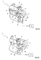
- Fig. 3a, 3b and 3c show the door handle assembly 1 according to Fig. 1 in three different states of operation.
- the door handle assembly 1 is unactuated, the stopper 13 is still removed from the non-activated mass lock 10.
- Fig. 3b the door handle assembly 1 is operated by a user by train on the handle 2 as intended.
- the traction means 5b is attracted by the positive guidance of the actuating lever 5a on the second pivot lever 8, and thus the door lock 6 is actuated.
- the stop 13 of the first pivot lever 7 has contacted the mass lock 10 and slightly shifted in the direction of the active position, while the extension 11 of the second pivot lever 8 could pass through the mass lock 10, however.
- the mass lock 10 has been deflected due to excessive acceleration in the active position, causing them wedged between bearing bracket 12 and extension 11, so that the pivot lever 7 and 8 are prevented from further movement.
Landscapes
- Lock And Its Accessories (AREA)
Abstract
Description
- Die vorliegende Erfindung betrifft eine Türgriffanordnung mit einer Handhabe zur mittelbaren Betätigung eines Türschlosses, die wenigstens einen in die Tür eingreifenden Lagerarm aufweist.
- Derartige Türgriffanordnungen werden insbesondere im Fahrzeugbau zur Betätigung der Schlösser von Türen oder Klappen verwendet. Dazu wird die Handhabe von einem Nutzer umgriffen und aus einer Ausgangsstellung in eine Gebrauchsstellung verbracht, wodurch das Türschloss, beispielsweise über einen Betätigungszug, betätigt wird und in Abhängigkeit vom Schließzustand die Tür oder Klappe gegenüber dessen Rahmen entriegelt.
- Derartige Türgriffanordnungen sind beispielsweise aus der
JP 8120980 A2 DE 2237998 A1 bekannt. Die gattungsbildendeEP 1 580 353 A1 offenbart eine Betätigungseinrichtung für ein Kraftfahrzeug-Türschloss; mit einem Türschloss-Betätiger, einer Griffplatte, einem die Griffplatte mit wenigstens einem Lagerarm durchgreifenden Handgriff, welcher Lagerarm an einer Rückseite der Griffplatte mit einem Lagerblock über eine parallel zur Längsachse des Handgriffs verlaufenden Steckachse schwenkbar angebunden ist. Dadurch lässt sich der Türgriff in einer Art Parallelverschiebung unter Beschreibung einer Schwenkbewegung von der Tür abziehen. Die Schwenkbewegung zeigt sich jedoch nachteilig in Bezug auf die Bedienbarkeit, da der Nutzer die Kurvenbewegung des Handgriffs ständig ausgleichen muss. Besonders bei hohen Fahrzeugen oder bei Betätigung durch Kinder ergeben sich hierbei Komforteinbußen. - Aufgabe der vorliegenden Erfindung ist es daher eine Türgriffanordnung der eingangs genannten Art bereitzustellen, die eine komfortable Bedienung und möglichst spielfreie Führung der Handhabe erlaubt.
- Diese Aufgabe wird durch die Merkmale des Patentanspruchs 1 gelöst.
- Ein Fahrzeug mit einer erfindungsgemäßen Türgriffanordnung wird in Patentanspruch 10 beansprucht.
- Türgriffanordnung mit einer Handhabe zur mittelbaren Betätigung eines Türschlosses, die wenigstens einen in die Tür eingreifenden Lagerarm aufweist, wobei der Lagerarm von einem ersten Schwenkhebel, der um eine erste Drehachse schwenkbar ist, und einem zweiten Schwenkhebel, der um eine zweite Drehachse schwenkbar ist, gelagert wird und wobei die Schwenkhebel an voneinander beabstandeten Angriffspunkten drehbeweglich an dem Lagerarm angreifen.
- Indem zwei Schwenkhebel mit inkongruenten Drehachsen an dem wenigstens einem Lagerarm mit voneinander beabstandeten Angriffspunkten drehbeweglich angreifen, ergibt sich ein Viergelenk, durch das die Handhabe zwangsgeführt wird. Durch geeignete Auslegung der Schwenkhebel lassen sich der Handhabe verschiedene Bewegungsabläufe auferlegen, wobei vorzugsweise nur geringe Schwenkanteile vorhanden sein sollten. Damit kann eine sehr komfortable Bedienung der Handhabe gewährleistet werden, da diese nahezu geradlinig relativ zur Tür bewegt werden kann. Unter Türen sollen vorliegend alle Elemente zum Öffnen bzw. Verschließen von Durchgängen, unabhängig von deren Ausrichtung der Schwenkachse im Raum, verstanden werden. Insbesondere zählen hierzu Klappen und Türen. Die Handhabe kann von einem Nutzer zumindest teilweise umgriffen werden, wodurch diese vorzugsweise mit einer Zugbewegung aus einer Ausgangsstellung in eine Gebrauchsstellung verbringbar ist. Spätestens in der Gebrauchsstellung ist ein mittelbar daran angeschlossenes Türschloss in Abhängigkeit von dessen Schließzustand betätigbar. Die Handhabe ist durch geeignete Mittel selbsttätig in die Ausgangsstellung rückstellend ausgebildet.
- In einer bevorzugten Ausführung sind die Drehachsen auf unterschiedlichen Seiten einer Geraden durch die Angriffspunkte angeordnet. Die daraus resultierende Anordnung der Schwenkhebel ermöglicht eine besonders vorteilhafte Kinematik der Türgriffanordnung, indem beginnend von der Ausgangsstellung eine geradlinige Bewegung erfolgt, die in Richtung der Gebrauchsstellung in eine leichte Schwenkbewegung übergeht. Besonders bevorzugt verlaufen die Drehachsen der Schwenkhebel parallel zur Längserstreckung der Handhabe.
- In einer bevorzugten Ausführung weist die Handhabe zwei endständig angeordnete Lagerarme auf, die von den Schwenkhebeln gelagert werden. Indem an den äußeren Enden der Handhabe jeweils ein Lagerarm ausgebildet ist, der von den beiden Schwenkhebeln kontaktiert wird, kann eine besonders spielfrei Führung der Handhabe sichergestellt werden.
- In einer bevorzugten Ausführung kann ein von einem der Schwenkhebel zwangsgeführter Betätigungszug das Türschloss betätigen. Besonders bevorzugt weist der Betätigungszug dazu einen Betätigungshebel und ein Zugmittel auf, wobei der Betätigungshebel mit einem an dem Schwenkhebel ausgebildeten Zahnsegment kämmt. Indem der Betätigungshebel direkt mit dem Zahnsegment eines der Schwenkhebel kämmt, wird jede Bewegung der Handhabe direkt in eine Schwenkbewegung des Betätigungshebels übertragen. An dem Betätigungshebel greift ein Zugmittel an, beispielsweise ein Bowdenzug oder eine Betätigungsstange, das zum Türschloss führt.
- In einer bevorzugten Ausführung unterbindet eine federvorgespannte, schwenkbar gelagerte Massensperre bei Überschreiten einer definierten Beschleunigung das Verschwenken eines der Schwenkhebel. Wird die Tür einer übermäßigen Beschleunigung ausgesetzt, so verhindert die Massensperre eine Bewegung der Handhabe und folglich eine Betätigung des Türschlosses. Dadurch lässt sich beispielsweise in verunfallten Fahrzeugen ein unbeabsichtigtes Öffnen der Tür verhindern.
- In einer bevorzugten Ausführung sind die Schwenkhebel und die Massensperre in einem gemeinsamen Lagerbügel gelagert. Der Lagerbügel ist fest innerhalb der Tür angeordnet und dient zur Lagerung der einzelnen Komponenten der Türgriffanordnung.
- In einer bevorzugten Ausführung verkeilt sich die Massensperre, bei Überschreiten einer definierten Beschleunigung, zwischen einem Fortsatz eines der Schwenkhebel und dem Lagerbügel. Dadurch wird die Bewegung des Schwenkhebels in einer Lage gestoppt, in der der Betätigungszug das Türschloss noch nicht betätigten konnte.
- In einer bevorzugten Ausführung ist mindestens einer der Schwenkhebel in Richtung der Ausgangsstellung federvorbelastet. Durch die Vorbelastung mittels einer Feder werden die Schwenkhebel stets wieder in Richtung der Ausgangsstellung rückgestellt, wenn der Nutzer die Handhabe loslässt.
- Ein Fahrzeug hat wenigstens eine erfindungsgemäße Türgriffanordnung. Die Türgriffanordnung ist insbesondere von außerhalb des Fahrzeugs bedienbar und dient der Betätigung einer eine Karosserieöffnung verschließenden Tür oder Klappe
- Weitere Einzelheiten und Vorteile der Erfindung ergeben sich aus der nachstehenden Beschreibung eines bevorzugten Ausführungsbeispiels unter Bezugnahme auf die Zeichnungen.
- Darin zeigen:
-
Fig. 1 eine Seitenansicht einer Türgriffanordnung in Ausgangsstellung und Gebrauchsstellung; -
Fig. 2 eine Ansicht einer in eine Tür eingebauten Türgriffanordnung; -
Fig. 3a eine Türgriffanordnung in Ausgangsstellung; -
Fig. 3b eine Türgriffanordnung in Gebrauchsstellung; -
Fig. 3c eine Türgriffanordnung mit aktivierter Massensperre. - Gemäß
Fig. 1 hat eine Türgriffanordnung 1 eine bügelförmige Handhabe 2 mit zwei jeweils endständig angeordneten Lagerarmen 4. Ein erster Schwenkhebel 7, der um eine erste Drehachse A schwenkbar ist, greift an den beiden Lagerarmen 4 im Punkt C an. Ein zweiter Schwenkhebel 8, der um eine zweite Drehachse B schwenkbar ist, greift an den beiden Lagerarmen 4 im Punkt D an. Wird durch die Punkte C und D eine Gerade E gelegt, so befinden sich die Drehachsen A und B auf unterschiedlichen Seiten dieser Gerade E und bilden somit ein Viergelenk. Die Schwenkhebel 7 und 8 werden, durch nicht dargestellte Federn, stets in Richtung Ausgangsstellung rückgestellt. Mit dem zweiten Schwenkhebel 8 ist ein Betätigungshebel 5a eines Betätigungszugs 5 gekoppelt. An dem Betätigungshebel 5a greift ein Zugmittel 5b an, dass mit einem Türschloss 6 in Wirkverbindung steht. Weiterhin hat eine Türgriffanordnung 1 eine (federvorbelastete) Massensperre 10, die mit einem Fortsatz 11 des zweiten Schwenkhebels 8 so zusammenwirken kann, dass bei Überschreiten einer definierten Beschleunigung der Türgriffanordnung 1 keine unbeabsichtigte Betätigung des Türschlosses 6 erfolgt. - In
Fig. 2 ist eine Türgriffanordnung 1 gemäßFig. 1 dargestellt, die in eine Tür 3 verbaut wurde. Dazu wird an der Tür 3 ein Lagerbügel 12 fest angeordnet, der die Komponenten der Türgriffanordnung 1 lagert. Die Handhabe 2 liegt außerhalb der Tür 3, wobei sich die Lagerarme 4 ins Türinnere erstrecken und dort von den Schwenkhebeln 7 und 8 gelagert werden. Der Betätigungshebel 5a kämmt mit einem an dem zweiten Schwenkhebel 8 ausgebildeten Zahnsegment 9. An dem ersten Schwenkhebel 7 ist ein Anschlag 13 ausgebildet, der die Massensperre 10 bei normaler Betätigung der Türgriffanordnung 1 in Richtung der aktiven Stellung drückt, bevor diese sich zwischen Fortsatz 11 des zweiten Schwenkhebels 8 und Lagerbügel 12 verkeilen kann. Letzteres ist nur dann der Fall, wenn die Massensperre 10 durch eine von außen einwirkende Beschleunigung in die aktive Stellung gedrückt wurde, bevor der Fortsatz 11 die Massensperre 10 passieren konnte. - Die
Fig. 3a, 3b und3c zeigen die Türgriffanordnung 1 gemäßFig. 1 in drei verschiedenen Betätigungszuständen. InFig. 3a ist die Türgriffanordnung 1 unbetätigt, wobei der Anschlag 13 noch von der nicht-aktivierten Massensperre 10 entfernt liegt. InFig. 3b ist die Türgriffanordnung 1 von einem Nutzer durch Zug an der Handhabe 2 bestimmungsgemäß betätigt. Wie ersichtlich ist, wird durch die Zwangsführung des Betätigungshebels 5a an dem zweiten Schwenkhebel 8 das Zugmittel 5b angezogen und somit das Türschloss 6 betätigt. Der Anschlag 13 des ersten Schwenkhebels 7 hat die Massensperre 10 kontaktiert und leicht in Richtung der aktiven Stellung verschoben, dabei konnte der Fortsatz 11 des zweiten Schwenkhebels 8 die Massensperre 10 jedoch passieren. InFig. 3c ist die Massensperre 10 aufgrund einer übermäßigen Beschleunigung in die aktive Stellung ausgelenkt worden, wodurch diese sich zwischen Lagerbügel 12 und Fortsatz 11 verkeilt, so dass die Schwenkhebel 7 und 8 an der weiteren Bewegung gehindert werden. -
- A
- erste Drehachse
- B
- zweite Drehachse
- C
- erster Angriffspunkt
- D
- zweiter Angriffspunkt
- E
- Gerade
- 1
- Türgriffanordnung
- 2
- Handhabe
- 3
- Tür
- 4
- Lagerarm
- 5
- Betätigungszug
- 5a
- Betätigungshebel
- 5b
- Zugmittel
- 6
- Türschloss
- 7
- erster Schwenkhebel
- 8
- zweiter Schwenkhebel
- 9
- Zahnsegment
- 10
- Massensperre
- 11
- Fortsatz
- 12
- Lagerbügel
- 13
- Anschlag
Claims (10)
- Türgriffanordnung (1) mit einer Handhabe (2) zur mittelbaren Betätigung eines Türschlosses (6), die wenigstens einen in die Tür (3) eingreifenden Lagerarm (4) aufweist, dadurch gekennzeichnet, dass der Lagerarm (4) von einem ersten Schwenkhebel (7), der um eine erste Drehachse (A) schwenkbar ist, und einem zweiten Schwenkhebel (8), der um eine zweite Drehachse (B) schwenkbar ist, gelagert wird, wobei die Schwenkhebel (7, 8) an voneinander beabstandeten Angriffspunkten (C, D) drehbeweglich an dem Lagerarm (4) angreifen.
- Türgriffanordnung nach Anspruch 1, dadurch gekennzeichnet, dass die Drehachsen (A, B) auf unterschiedlichen Seiten einer Geraden (E) durch die Angriffspunkte (C, D) angeordnet sind.
- Türgriffanordnung nach Anspruch 1 oder 2, dadurch gekennzeichnet, dass die Handhabe (2) zwei endständig angeordnete Lagerarme (4) aufweist, die von den Schwenkhebeln (7, 8) gelagert werden.
- Türgriffanordnung nach einem der Ansprüche 1 bis 3, dadurch gekennzeichnet, dass ein von einem der Schwenkhebel (7, 8) zwangsgeführter Betätigungszug (5) das Türschloss (6) betätigen kann.
- Türgriffanordnung nach Anspruch 4, dadurch gekennzeichnet, dass der Betätigungszug (5) einen Betätigungshebel (5a) und ein Zugmittel (5b) aufweist, wobei der Betätigungshebel (5a) mit einem an dem Schwenkhebel (7, 8) ausgebildeten Zahnsegment (9) kämmt.
- Türgriffanordnung nach einem der Ansprüche 1 bis 5, dadurch gekennzeichnet, dass eine federvorgespannte, schwenkbar gelagerte Massensperre (10) bei Überschreiten einer definierten Beschleunigung das Verschwenken eines der Schwenkhebel (7, 8) unterbindet.
- Türgriffanordnung nach Anspruch 6, dadurch gekennzeichnet, dass die Schwenkhebel (7, 8) und die Massensperre (10) in einem gemeinsamen Lagerbügel (12) gelagert sind.
- Türgriffanordnung nach Anspruch 7, dadurch gekennzeichnet, dass sich die Massensperre (10), bei Überschreiten einer definierten Beschleunigung, zwischen einem Fortsatz (11) eines der Schwenkhebel (7, 8) und dem Lagerbügel (12) verkeilt.
- Türgriffanordnung nach einem der Ansprüche 1 bis 8, dadurch gekennzeichnet, dass mindestens einer der Schwenkhebel (7, 8) in Richtung einer Ausgangsstellung federvorbelastet ist.
- Fahrzeug mit wenigstens einer Türgriffanordnung (1) nach Anspruch 1.
Applications Claiming Priority (1)
| Application Number | Priority Date | Filing Date | Title |
|---|---|---|---|
| DE102011018750A DE102011018750A1 (de) | 2011-04-27 | 2011-04-27 | Türgriffanordnung |
Publications (3)
| Publication Number | Publication Date |
|---|---|
| EP2518244A2 true EP2518244A2 (de) | 2012-10-31 |
| EP2518244A3 EP2518244A3 (de) | 2017-06-28 |
| EP2518244B1 EP2518244B1 (de) | 2018-08-29 |
Family
ID=45977113
Family Applications (1)
| Application Number | Title | Priority Date | Filing Date |
|---|---|---|---|
| EP12002464.1A Not-in-force EP2518244B1 (de) | 2011-04-27 | 2012-04-05 | Türgriffanordnung |
Country Status (2)
| Country | Link |
|---|---|
| EP (1) | EP2518244B1 (de) |
| DE (1) | DE102011018750A1 (de) |
Cited By (1)
| Publication number | Priority date | Publication date | Assignee | Title |
|---|---|---|---|---|
| CN108193960A (zh) * | 2017-12-29 | 2018-06-22 | 郑州日产汽车有限公司 | 一种新型车门外开机构 |
Family Cites Families (9)
| Publication number | Priority date | Publication date | Assignee | Title |
|---|---|---|---|---|
| JPS5411575B1 (de) | 1971-07-28 | 1979-05-16 | ||
| FR2280522B1 (fr) * | 1974-07-31 | 1977-01-07 | Peugeot & Renault | Dispositif de commande pour deverrouillage et manoeuvre de porte coulissante par palette a double articulation |
| FR2616833B1 (fr) * | 1987-06-18 | 1989-10-20 | Rockwell Cim | Dispositif de commande manuelle d'ouverture de porte de vehicule |
| DE3915737A1 (de) * | 1989-05-13 | 1990-11-15 | Hella Kg Hueck & Co | Einrichtung zum betaetigen von schwenkbaren und/oder verschiebbaren karosserieteilen an kraftfahrzeugen |
| JPH08120980A (ja) | 1994-10-20 | 1996-05-14 | Sakae Riken Kogyo Kk | ドアハンドル装置 |
| FR2816073B1 (fr) * | 2000-10-26 | 2003-09-12 | Peugeot Citroen Automobiles Sa | Dispositif de commande d'un ou de plusieurs mecanismes, notamment d'ouvrant de vehicule automobile |
| DE102004015136B3 (de) | 2004-03-27 | 2005-09-29 | Dr.Ing.H.C. F. Porsche Ag | Betätigungseinrichtung für ein Kraftfahrzeug-Türschloss |
| DE102008019335A1 (de) * | 2007-04-18 | 2008-10-23 | Friedr. Fingscheidt Gmbh | Türgriff mit Betätigungseinrichtung zur Anordnung in einem Kraftfahrzeug |
| DE102009053553A1 (de) * | 2009-11-18 | 2011-05-19 | Huf Hülsbeck & Fürst Gmbh & Co. Kg | Sicherheitstürgriff |
-
2011
- 2011-04-27 DE DE102011018750A patent/DE102011018750A1/de not_active Ceased
-
2012
- 2012-04-05 EP EP12002464.1A patent/EP2518244B1/de not_active Not-in-force
Cited By (1)
| Publication number | Priority date | Publication date | Assignee | Title |
|---|---|---|---|---|
| CN108193960A (zh) * | 2017-12-29 | 2018-06-22 | 郑州日产汽车有限公司 | 一种新型车门外开机构 |
Also Published As
| Publication number | Publication date |
|---|---|
| EP2518244B1 (de) | 2018-08-29 |
| DE102011018750A1 (de) | 2012-10-31 |
| EP2518244A3 (de) | 2017-06-28 |
Similar Documents
| Publication | Publication Date | Title |
|---|---|---|
| EP2766543B1 (de) | Betätigungseinrichtung für ein kraftfahrzeug-türschloss | |
| EP2342405B1 (de) | Kraftfahrzeugschloss | |
| EP3049598B1 (de) | Kraftfahrzeugtürgriff | |
| EP3371398B1 (de) | Kraftfahrzeugschloss | |
| EP2543801B1 (de) | Sichere Türgriffeinheit | |
| EP3612695B1 (de) | Schloss für ein kraftfahrzeug | |
| EP1231341B1 (de) | Betätigungsvorrichtung für eine Haube eines Kraftfahrzeugs | |
| DE19841670A1 (de) | Schließeinrichtung | |
| EP3126600A1 (de) | Betätigungseinrichtung für ein kraftfahrzeugschloss | |
| WO2008129003A2 (de) | Türgriff mit betätigungseinrichtung zur anordnung in einem kraftfahrzeug | |
| EP4133151B1 (de) | Türaufsteller für ein kraftfahrzeug | |
| DE102017102549A1 (de) | Kraftfahrzeugschloss | |
| EP2811090B1 (de) | Türgriffanordnung für ein kraftfahrzeug | |
| WO2020048653A1 (de) | Türgriffanordnung für ein kraftfahrzeug | |
| WO2015014344A1 (de) | Kraftfahrzeugtür | |
| DE102018109477A1 (de) | Kraftfahrzeug-Antriebsanordnung | |
| EP2518244B1 (de) | Türgriffanordnung | |
| EP1849940B1 (de) | Schliessvorrichtung für eine Schiebetür mit Arretierungsmittel zum Fixieren der geöffneten Schiebetür | |
| DE102016109454A1 (de) | Kraftfahrzeug-Schlosssystem | |
| DE10339542B4 (de) | Kraftfahrzeugtürverschluss | |
| DE102017118489A1 (de) | Fahrzeug-Griffanordnung | |
| DE102019128637A1 (de) | Kraftfahrzeugschloss | |
| DE102019111305A1 (de) | Aufstellvorrichtung für eine Kraftfahrzeugtür | |
| DE10325640A1 (de) | Haubenverschluss | |
| DE20308079U1 (de) | Motorhaubenverschluss |
Legal Events
| Date | Code | Title | Description |
|---|---|---|---|
| PUAI | Public reference made under article 153(3) epc to a published international application that has entered the european phase |
Free format text: ORIGINAL CODE: 0009012 |
|
| AK | Designated contracting states |
Kind code of ref document: A2 Designated state(s): AL AT BE BG CH CY CZ DE DK EE ES FI FR GB GR HR HU IE IS IT LI LT LU LV MC MK MT NL NO PL PT RO RS SE SI SK SM TR |
|
| AX | Request for extension of the european patent |
Extension state: BA ME |
|
| PUAL | Search report despatched |
Free format text: ORIGINAL CODE: 0009013 |
|
| AK | Designated contracting states |
Kind code of ref document: A3 Designated state(s): AL AT BE BG CH CY CZ DE DK EE ES FI FR GB GR HR HU IE IS IT LI LT LU LV MC MK MT NL NO PL PT RO RS SE SI SK SM TR |
|
| AX | Request for extension of the european patent |
Extension state: BA ME |
|
| RIC1 | Information provided on ipc code assigned before grant |
Ipc: E05B 65/20 00000000AFI20170523BHEP Ipc: E05B 7/00 20060101ALI20170523BHEP |
|
| STAA | Information on the status of an ep patent application or granted ep patent |
Free format text: STATUS: REQUEST FOR EXAMINATION WAS MADE |
|
| 17P | Request for examination filed |
Effective date: 20180102 |
|
| RBV | Designated contracting states (corrected) |
Designated state(s): AL AT BE BG CH CY CZ DE DK EE ES FI FR GB GR HR HU IE IS IT LI LT LU LV MC MK MT NL NO PL PT RO RS SE SI SK SM TR |
|
| REG | Reference to a national code |
Ref country code: DE Ref legal event code: R079 Ref document number: 502012013312 Country of ref document: DE Free format text: PREVIOUS MAIN CLASS: E05B0065200000 Ipc: E05B0077060000 |
|
| RIC1 | Information provided on ipc code assigned before grant |
Ipc: E05B 85/18 20140101ALI20180425BHEP Ipc: E05B 77/06 20140101AFI20180425BHEP Ipc: E05B 79/20 20140101ALI20180425BHEP |
|
| GRAP | Despatch of communication of intention to grant a patent |
Free format text: ORIGINAL CODE: EPIDOSNIGR1 |
|
| STAA | Information on the status of an ep patent application or granted ep patent |
Free format text: STATUS: GRANT OF PATENT IS INTENDED |
|
| INTG | Intention to grant announced |
Effective date: 20180606 |
|
| GRAS | Grant fee paid |
Free format text: ORIGINAL CODE: EPIDOSNIGR3 |
|
| GRAA | (expected) grant |
Free format text: ORIGINAL CODE: 0009210 |
|
| STAA | Information on the status of an ep patent application or granted ep patent |
Free format text: STATUS: THE PATENT HAS BEEN GRANTED |
|
| AK | Designated contracting states |
Kind code of ref document: B1 Designated state(s): AL AT BE BG CH CY CZ DE DK EE ES FI FR GB GR HR HU IE IS IT LI LT LU LV MC MK MT NL NO PL PT RO RS SE SI SK SM TR |
|
| REG | Reference to a national code |
Ref country code: GB Ref legal event code: FG4D Free format text: NOT ENGLISH |
|
| REG | Reference to a national code |
Ref country code: CH Ref legal event code: EP |
|
| REG | Reference to a national code |
Ref country code: AT Ref legal event code: REF Ref document number: 1035316 Country of ref document: AT Kind code of ref document: T Effective date: 20180915 |
|
| REG | Reference to a national code |
Ref country code: IE Ref legal event code: FG4D Free format text: LANGUAGE OF EP DOCUMENT: GERMAN |
|
| REG | Reference to a national code |
Ref country code: DE Ref legal event code: R096 Ref document number: 502012013312 Country of ref document: DE |
|
| REG | Reference to a national code |
Ref country code: NL Ref legal event code: MP Effective date: 20180829 |
|
| REG | Reference to a national code |
Ref country code: LT Ref legal event code: MG4D |
|
| PG25 | Lapsed in a contracting state [announced via postgrant information from national office to epo] |
Ref country code: IS Free format text: LAPSE BECAUSE OF FAILURE TO SUBMIT A TRANSLATION OF THE DESCRIPTION OR TO PAY THE FEE WITHIN THE PRESCRIBED TIME-LIMIT Effective date: 20181229 Ref country code: NO Free format text: LAPSE BECAUSE OF FAILURE TO SUBMIT A TRANSLATION OF THE DESCRIPTION OR TO PAY THE FEE WITHIN THE PRESCRIBED TIME-LIMIT Effective date: 20181129 Ref country code: SE Free format text: LAPSE BECAUSE OF FAILURE TO SUBMIT A TRANSLATION OF THE DESCRIPTION OR TO PAY THE FEE WITHIN THE PRESCRIBED TIME-LIMIT Effective date: 20180829 Ref country code: RS Free format text: LAPSE BECAUSE OF FAILURE TO SUBMIT A TRANSLATION OF THE DESCRIPTION OR TO PAY THE FEE WITHIN THE PRESCRIBED TIME-LIMIT Effective date: 20180829 Ref country code: FI Free format text: LAPSE BECAUSE OF FAILURE TO SUBMIT A TRANSLATION OF THE DESCRIPTION OR TO PAY THE FEE WITHIN THE PRESCRIBED TIME-LIMIT Effective date: 20180829 Ref country code: BG Free format text: LAPSE BECAUSE OF FAILURE TO SUBMIT A TRANSLATION OF THE DESCRIPTION OR TO PAY THE FEE WITHIN THE PRESCRIBED TIME-LIMIT Effective date: 20181129 Ref country code: NL Free format text: LAPSE BECAUSE OF FAILURE TO SUBMIT A TRANSLATION OF THE DESCRIPTION OR TO PAY THE FEE WITHIN THE PRESCRIBED TIME-LIMIT Effective date: 20180829 Ref country code: LT Free format text: LAPSE BECAUSE OF FAILURE TO SUBMIT A TRANSLATION OF THE DESCRIPTION OR TO PAY THE FEE WITHIN THE PRESCRIBED TIME-LIMIT Effective date: 20180829 Ref country code: GR Free format text: LAPSE BECAUSE OF FAILURE TO SUBMIT A TRANSLATION OF THE DESCRIPTION OR TO PAY THE FEE WITHIN THE PRESCRIBED TIME-LIMIT Effective date: 20181130 |
|
| PG25 | Lapsed in a contracting state [announced via postgrant information from national office to epo] |
Ref country code: HR Free format text: LAPSE BECAUSE OF FAILURE TO SUBMIT A TRANSLATION OF THE DESCRIPTION OR TO PAY THE FEE WITHIN THE PRESCRIBED TIME-LIMIT Effective date: 20180829 Ref country code: AL Free format text: LAPSE BECAUSE OF FAILURE TO SUBMIT A TRANSLATION OF THE DESCRIPTION OR TO PAY THE FEE WITHIN THE PRESCRIBED TIME-LIMIT Effective date: 20180829 Ref country code: LV Free format text: LAPSE BECAUSE OF FAILURE TO SUBMIT A TRANSLATION OF THE DESCRIPTION OR TO PAY THE FEE WITHIN THE PRESCRIBED TIME-LIMIT Effective date: 20180829 |
|
| PG25 | Lapsed in a contracting state [announced via postgrant information from national office to epo] |
Ref country code: CZ Free format text: LAPSE BECAUSE OF FAILURE TO SUBMIT A TRANSLATION OF THE DESCRIPTION OR TO PAY THE FEE WITHIN THE PRESCRIBED TIME-LIMIT Effective date: 20180829 Ref country code: RO Free format text: LAPSE BECAUSE OF FAILURE TO SUBMIT A TRANSLATION OF THE DESCRIPTION OR TO PAY THE FEE WITHIN THE PRESCRIBED TIME-LIMIT Effective date: 20180829 Ref country code: ES Free format text: LAPSE BECAUSE OF FAILURE TO SUBMIT A TRANSLATION OF THE DESCRIPTION OR TO PAY THE FEE WITHIN THE PRESCRIBED TIME-LIMIT Effective date: 20180829 Ref country code: PL Free format text: LAPSE BECAUSE OF FAILURE TO SUBMIT A TRANSLATION OF THE DESCRIPTION OR TO PAY THE FEE WITHIN THE PRESCRIBED TIME-LIMIT Effective date: 20180829 Ref country code: EE Free format text: LAPSE BECAUSE OF FAILURE TO SUBMIT A TRANSLATION OF THE DESCRIPTION OR TO PAY THE FEE WITHIN THE PRESCRIBED TIME-LIMIT Effective date: 20180829 Ref country code: IT Free format text: LAPSE BECAUSE OF FAILURE TO SUBMIT A TRANSLATION OF THE DESCRIPTION OR TO PAY THE FEE WITHIN THE PRESCRIBED TIME-LIMIT Effective date: 20180829 |
|
| PG25 | Lapsed in a contracting state [announced via postgrant information from national office to epo] |
Ref country code: DK Free format text: LAPSE BECAUSE OF FAILURE TO SUBMIT A TRANSLATION OF THE DESCRIPTION OR TO PAY THE FEE WITHIN THE PRESCRIBED TIME-LIMIT Effective date: 20180829 Ref country code: SM Free format text: LAPSE BECAUSE OF FAILURE TO SUBMIT A TRANSLATION OF THE DESCRIPTION OR TO PAY THE FEE WITHIN THE PRESCRIBED TIME-LIMIT Effective date: 20180829 Ref country code: SK Free format text: LAPSE BECAUSE OF FAILURE TO SUBMIT A TRANSLATION OF THE DESCRIPTION OR TO PAY THE FEE WITHIN THE PRESCRIBED TIME-LIMIT Effective date: 20180829 |
|
| REG | Reference to a national code |
Ref country code: DE Ref legal event code: R097 Ref document number: 502012013312 Country of ref document: DE |
|
| PLBE | No opposition filed within time limit |
Free format text: ORIGINAL CODE: 0009261 |
|
| STAA | Information on the status of an ep patent application or granted ep patent |
Free format text: STATUS: NO OPPOSITION FILED WITHIN TIME LIMIT |
|
| 26N | No opposition filed |
Effective date: 20190531 |
|
| PG25 | Lapsed in a contracting state [announced via postgrant information from national office to epo] |
Ref country code: SI Free format text: LAPSE BECAUSE OF FAILURE TO SUBMIT A TRANSLATION OF THE DESCRIPTION OR TO PAY THE FEE WITHIN THE PRESCRIBED TIME-LIMIT Effective date: 20180829 |
|
| REG | Reference to a national code |
Ref country code: CH Ref legal event code: PL |
|
| REG | Reference to a national code |
Ref country code: BE Ref legal event code: MM Effective date: 20190430 |
|
| PG25 | Lapsed in a contracting state [announced via postgrant information from national office to epo] |
Ref country code: LU Free format text: LAPSE BECAUSE OF NON-PAYMENT OF DUE FEES Effective date: 20190405 Ref country code: MC Free format text: LAPSE BECAUSE OF FAILURE TO SUBMIT A TRANSLATION OF THE DESCRIPTION OR TO PAY THE FEE WITHIN THE PRESCRIBED TIME-LIMIT Effective date: 20180829 |
|
| PG25 | Lapsed in a contracting state [announced via postgrant information from national office to epo] |
Ref country code: CH Free format text: LAPSE BECAUSE OF NON-PAYMENT OF DUE FEES Effective date: 20190430 Ref country code: LI Free format text: LAPSE BECAUSE OF NON-PAYMENT OF DUE FEES Effective date: 20190430 |
|
| PG25 | Lapsed in a contracting state [announced via postgrant information from national office to epo] |
Ref country code: BE Free format text: LAPSE BECAUSE OF NON-PAYMENT OF DUE FEES Effective date: 20190430 |
|
| PG25 | Lapsed in a contracting state [announced via postgrant information from national office to epo] |
Ref country code: TR Free format text: LAPSE BECAUSE OF FAILURE TO SUBMIT A TRANSLATION OF THE DESCRIPTION OR TO PAY THE FEE WITHIN THE PRESCRIBED TIME-LIMIT Effective date: 20180829 |
|
| PG25 | Lapsed in a contracting state [announced via postgrant information from national office to epo] |
Ref country code: IE Free format text: LAPSE BECAUSE OF NON-PAYMENT OF DUE FEES Effective date: 20190405 |
|
| PG25 | Lapsed in a contracting state [announced via postgrant information from national office to epo] |
Ref country code: PT Free format text: LAPSE BECAUSE OF FAILURE TO SUBMIT A TRANSLATION OF THE DESCRIPTION OR TO PAY THE FEE WITHIN THE PRESCRIBED TIME-LIMIT Effective date: 20181229 |
|
| REG | Reference to a national code |
Ref country code: AT Ref legal event code: MM01 Ref document number: 1035316 Country of ref document: AT Kind code of ref document: T Effective date: 20190405 |
|
| PG25 | Lapsed in a contracting state [announced via postgrant information from national office to epo] |
Ref country code: AT Free format text: LAPSE BECAUSE OF NON-PAYMENT OF DUE FEES Effective date: 20190405 |
|
| PG25 | Lapsed in a contracting state [announced via postgrant information from national office to epo] |
Ref country code: CY Free format text: LAPSE BECAUSE OF FAILURE TO SUBMIT A TRANSLATION OF THE DESCRIPTION OR TO PAY THE FEE WITHIN THE PRESCRIBED TIME-LIMIT Effective date: 20180829 |
|
| PG25 | Lapsed in a contracting state [announced via postgrant information from national office to epo] |
Ref country code: HU Free format text: LAPSE BECAUSE OF FAILURE TO SUBMIT A TRANSLATION OF THE DESCRIPTION OR TO PAY THE FEE WITHIN THE PRESCRIBED TIME-LIMIT; INVALID AB INITIO Effective date: 20120405 Ref country code: MT Free format text: LAPSE BECAUSE OF FAILURE TO SUBMIT A TRANSLATION OF THE DESCRIPTION OR TO PAY THE FEE WITHIN THE PRESCRIBED TIME-LIMIT Effective date: 20180829 |
|
| PG25 | Lapsed in a contracting state [announced via postgrant information from national office to epo] |
Ref country code: MK Free format text: LAPSE BECAUSE OF FAILURE TO SUBMIT A TRANSLATION OF THE DESCRIPTION OR TO PAY THE FEE WITHIN THE PRESCRIBED TIME-LIMIT Effective date: 20180829 |
|
| P01 | Opt-out of the competence of the unified patent court (upc) registered |
Effective date: 20230530 |
|
| PGFP | Annual fee paid to national office [announced via postgrant information from national office to epo] |
Ref country code: FR Payment date: 20230425 Year of fee payment: 12 Ref country code: DE Payment date: 20230430 Year of fee payment: 12 |
|
| PGFP | Annual fee paid to national office [announced via postgrant information from national office to epo] |
Ref country code: GB Payment date: 20230420 Year of fee payment: 12 |
|
| REG | Reference to a national code |
Ref country code: DE Ref legal event code: R119 Ref document number: 502012013312 Country of ref document: DE |
|
| GBPC | Gb: european patent ceased through non-payment of renewal fee |
Effective date: 20240405 |
|
| PG25 | Lapsed in a contracting state [announced via postgrant information from national office to epo] |
Ref country code: DE Free format text: LAPSE BECAUSE OF NON-PAYMENT OF DUE FEES Effective date: 20241105 |
|
| PG25 | Lapsed in a contracting state [announced via postgrant information from national office to epo] |
Ref country code: GB Free format text: LAPSE BECAUSE OF NON-PAYMENT OF DUE FEES Effective date: 20240405 |
|
| PG25 | Lapsed in a contracting state [announced via postgrant information from national office to epo] |
Ref country code: FR Free format text: LAPSE BECAUSE OF NON-PAYMENT OF DUE FEES Effective date: 20240430 |
|
| PG25 | Lapsed in a contracting state [announced via postgrant information from national office to epo] |
Ref country code: GB Free format text: LAPSE BECAUSE OF NON-PAYMENT OF DUE FEES Effective date: 20240405 Ref country code: FR Free format text: LAPSE BECAUSE OF NON-PAYMENT OF DUE FEES Effective date: 20240430 Ref country code: DE Free format text: LAPSE BECAUSE OF NON-PAYMENT OF DUE FEES Effective date: 20241105 |