EP2516276B1 - Procede et machine pour fabriquer un emballage sterile muni d'un bec verseur interieur ainsi que l'emballage obtenu - Google Patents
Procede et machine pour fabriquer un emballage sterile muni d'un bec verseur interieur ainsi que l'emballage obtenu Download PDFInfo
- Publication number
- EP2516276B1 EP2516276B1 EP10807766.0A EP10807766A EP2516276B1 EP 2516276 B1 EP2516276 B1 EP 2516276B1 EP 10807766 A EP10807766 A EP 10807766A EP 2516276 B1 EP2516276 B1 EP 2516276B1
- Authority
- EP
- European Patent Office
- Prior art keywords
- film
- pouch
- fitments
- sterilized
- fitment
- Prior art date
- Legal status (The legal status is an assumption and is not a legal conclusion. Google has not performed a legal analysis and makes no representation as to the accuracy of the status listed.)
- Not-in-force
Links
Images


Classifications
-
- B—PERFORMING OPERATIONS; TRANSPORTING
- B65—CONVEYING; PACKING; STORING; HANDLING THIN OR FILAMENTARY MATERIAL
- B65B—MACHINES, APPARATUS OR DEVICES FOR, OR METHODS OF, PACKAGING ARTICLES OR MATERIALS; UNPACKING
- B65B55/00—Preserving, protecting or purifying packages or package contents in association with packaging
- B65B55/02—Sterilising, e.g. of complete packages
- B65B55/04—Sterilising wrappers or receptacles prior to, or during, packaging
- B65B55/10—Sterilising wrappers or receptacles prior to, or during, packaging by liquids or gases
- B65B55/103—Sterilising flat or tubular webs
-
- B—PERFORMING OPERATIONS; TRANSPORTING
- B65—CONVEYING; PACKING; STORING; HANDLING THIN OR FILAMENTARY MATERIAL
- B65B—MACHINES, APPARATUS OR DEVICES FOR, OR METHODS OF, PACKAGING ARTICLES OR MATERIALS; UNPACKING
- B65B61/00—Auxiliary devices, not otherwise provided for, for operating on sheets, blanks, webs, binding material, containers or packages
- B65B61/18—Auxiliary devices, not otherwise provided for, for operating on sheets, blanks, webs, binding material, containers or packages for making package-opening or unpacking elements
- B65B61/186—Auxiliary devices, not otherwise provided for, for operating on sheets, blanks, webs, binding material, containers or packages for making package-opening or unpacking elements by applying or incorporating rigid fittings, e.g. discharge spouts
Definitions
- This invention relates to an aseptic packaging system, packaging process, and package in which the package includes a sterilized internal fitment.
- Aseptic food packaging is a well known method of packaging a food product. Aseptic packaging requires special treatment and handling of the food product as well as all of the equipment that contacts the food product until it is secured inside of a hermetic container. This method includes the destruction of all molds, yeasts and pathogens of concern for the specific food product.
- the FDA has jurisdiction over all food packaged in the Low Acid range (4.4 pH and higher) while food packaged in the High Acid (4.4 pH and lower) range is confirmed by the food processor utilizing that technology.
- Common methods employed in attaining this commercial sterility include steam, heated air, and chemicals. Sometimes the term Commercially Sterile is simply referred to as sterile.
- thermoplastic film In general, in the field of packaging food and non-food liquid and/or flowable and/or pumpable food and non-food products, a convenient method of packaging such products in thermoplastic film has been developed and is generally known as a vertical form/fill/seal process.
- a tube In such a process a tube is typically formed from a laminate including e.g. various nylons, PET and foil, or a coextruded multi-layer thermoplastic film, a longitudinal fin or lap seal is made, and an end seal is made by transversely sealing across the tube with heated seal bars to form a conveniently wide heat seal and, consequently, producing a pouch ready to receive a product.
- the seal can be made by any of various sealing methods known to those of skill in the art, including heat sealing, ultrasonic sealing, impulse sealing, constant heat sealing, radio frequency sealing, and the like. After the seal, e.g. a heat seal is made, the bag or pouch is filled and then another transverse heat seal is made across the width of the tube in a relatively wide band. After cooling, this seal is transversely severed to separate the filled bag from the next pouch to be filled. Thus, one wide band seal serves as the bottom seal for one pouch and the top seal for another.
- VFFS Vertical form/fill/seal packaging systems
- ONPACKTM flowable food packaging system marketed by Cryovac/Sealed Air Corporation.
- the VFFS process is known to those of skill in the art, and described for example in U.S. Patent Nos. 4,506,494 (Shimoyama et al. ), 4,589,247 (Tsuruta et al ), 4,656,818 (Shimoyama et al.
- lay-flat thermoplastic film is advanced over a forming device to form a tube, a longitudinal (vertical) fin or lap seal is made, and a bottom end seal is made by transversely sealing across the tube with heated seal bars.
- a liquid, flowable, and/or pumpable product such as a liquid, semiliquid, or paste, with or without particulates therein, is introduced through a central, vertical fill tube to the formed tubular film. Squeeze rollers spaced apart and above the bottom end seal squeeze the filled tube and pinch the walls of the flattened tube together.
- the process can be a two-stage process where the creation of a transverse heat seal occurs at one stage in the process, and then, downstream of the first stage, a separate pair of cooling/clamping means contact the just-formed transverse heat seal to cool and thus strengthen the seal.
- VFFS processes an upper transverse seal of a first pouch, and the lower transverse seal of a following pouch, are made, and the pouches cut and thereby separated between two portions of the transverse seals, without the need for a separate step to clamp, cool, and cut the seals.
- a commercial example of an apparatus embodying this more simplified process is the ONPACKTM 2002 VFFS packaging machine marketed by Cryovac/Sealed Air Corporation.
- U.S. Pat. No. 4,603,793 (Stern ), incorporated herein by reference in its entirety, discloses a coupling means 6a which is mounted on the inside wall of a pouch.
- Such coupling means, or fitment offer several advantages in packaging food products, such as the capability of connecting the fitment to a pumping device. This permits the contents of the package to be dispensed in a controllable way.
- the particular coupling device described in U.S. Pat. No. 4,603,793 is mounted inside the pouch.
- Packaging systems combining the Onpack (TM) system with the fitment technology of U.S. Pat. No. 4,603,793 have proven effective in providing a pouch making system where the pouch, containing a food product, includes an internal fitment.
- US 2003/177739 discloses a packaging system in accordance with the pre-characterizing section of claim 1, a method in accordance with the pre-characterizing section of claim 13 and a package in accordance with the pre-characterizing section of claim 15.
- an aseptic packaging system comprises:
- a method of making an aseptic package in a vertical/fill/seal process comprising:
- an aseptic package comprises:
- Aseptic herein refers to a system and/or process wherein a commercially sterilized container or packaging material, e.g. a pouch constructed in a vertical form/fill/seal process, is filled with a commercially sterilized product, such as a food product, in a hygienic environment. The product is thus rendered shelf stable in normal nonrefrigerated conditions.
- Aseptic is also used herein to refer to the resulting filled and closed package. The package or packaging material, and the product, are typically separately sterilized before filling.
- EAO Ethylene/alpha-olefin copolymer
- EAO includes heterogeneous materials such as linear medium density polyethylene (LMDPE), linear low density polyethylene (LLDPE), and very low and ultra low density polyethylene (VLDPE and ULDPE); single-site catalyzed materials such as homogeneous linear ethylene/alpha olefin copolymers and long chain branched ethylene/alpha olefin copolymers; and multicomponent ethylene/alpha-olefin interpenetrating network resin (or "IPN resin").
- LMDPE linear medium density polyethylene
- LLDPE linear low density polyethylene
- VLDPE and ULDPE very low and ultra low density polyethylene
- IPN resin multicomponent ethylene/alpha-olefin interpenetrating network resin
- Film is used herein to mean a thermoplastic film, laminate, or web, either multilayer or monolayer, that may be used in connection with the present invention.
- Film can be of any suitable thickness, e.g. between 0.1 and 30 mils.
- Fiber seal is used herein to mean folding one edge of a film towards the opposite edge of the film, and sealing the facing inner surfaces together.
- “Fitment” is used herein to mean a device that can be attached to a surface of a film, the film to be made into a pouch wherein the surface forms either the internal or external surface of the pouch, wherein the pouch can be filled with a sterile product and sealed to form an aseptic package, and wherein the fitment facilitates the removal of the sterile product from the package.
- “Lap seal” is used herein to mean a seal made by sealing an inside surface of a film to an outside surface of a film.
- Longitudinal seal herein refers to a fin seal or lap seal.
- Olefinic and the like herein refers to a polymer or copolymer derived at least in part from an olefinic monomer.
- Oxygen barrier and the like herein refers to materials having an oxygen permeability, of the barrier material, less than 500 cm 3 O 2 /m 2 • day • atmosphere (tested at 1 mil thick and at 25 °C, 0% RH according to ASTM D3985), such as less than 100, less than 50, less than 25, less than 10, less than 5, and less than 1 cm 3 O 2 / m 2 • day • atmosphere.
- polymeric materials useful as oxygen barrier materials are ethylene/vinyl alcohol copolymer (EVOH), polyvinylidene dichloride (PVDC), vinylidene chloride/ methyl acrylate copolymer, vinylidene chloride/ vinyl chloride copolymer, polyamide (nylon), and polyester (PET).
- Polymer and the like herein means a homopolymer, but also a copolymer thereof, including terpolymer, tetrapolymer, block copolymer, etc.
- Pouch herein means a pouch or bag.
- Registration device herein refers to any mark, such as an eye spot, pattern, or feature of a film, that facilitates the advancement of the film, in a controlled manner, into and/or through a packaging machine, where the film is used to make individual packages.
- the device can be e.g. printed or placed in uniformly spaced fashion along or near an edge of the web or discrete tape, i.e. registration marks, or in an area near the middle of a web that does not interfere with decorative printed graphics. These marks are used in connection with appropriate sensors to controllably advance the film.
- the internal fitments and/or (if present) external fitments can function as a registration device, and can be detected by sensors, and it may not be necessary to print registration marks on the film.
- “Seal” herein means a bond between two thermoplastic surfaces, e.g. as produced by heat sealing, radio frequency (RF) sealing, ultrasonic sealing, or the like.
- “Sealant” is a polymeric material or blend of materials, such as olefinic polymer or copolymer such as an ethylenic polymer or copolymer, that can form a surface of the film, and form a bond between two thermoplastic surfaces.
- Thermoplastic herein includes plastic materials that when heated to a softening or melting point may be reshaped without significant thermal degradation (burning). Thermoplastic includes both materials that are not crosslinked, or that are crosslinked by chemical or radiation means.
- the system in accordance with the invention is an automated vertical form/fill/seal (VFFS) system for aseptically packaging pumpable products, including liquid products and those with small particulates.
- the system in one embodiment is a single head stainless steel apparatus that can produce packages with headspace or no headspace.
- the finished packages can be used in e.g. retail and food service (hospital, restaurant, or institutional) end-use applications.
- Packages of e.g. from 3 to 10 liters in volume, e.g. 2 to 10 liters or 2 to 5 liters, can be produced. With appropriate modifications, packages smaller or larger than these volumes can be produced.
- a moving cooling bar can be used in connection with the production of transverse seals during the packaging process, to accelerate cooling of the transverse seals.
- Coextruded or laminated films, printed or unprinted can be used in the production of aseptic packages. Eye spots or other registration marks can optionally be installed on lay-flat film for use in the system, to control the production length of individual packages. The internal fitments themselves once installed on the film can serve as registration marks with suitable use of sensors to control the production of packages.
- the system uses in one embodiment servocontrol for most motions and a single PLC (programmable logic controller with suitable software) to control all system functions.
- the aseptic packaging system 10 in accordance with the invention includes a film unwind device 12 for unwinding a film.
- Thermoplastic film 30 is stored on a first roll 32 supported by first film support shaft 34.
- the film 30 is fed from the roll 32 as needed and advanced as described further herein.
- a second roll 36 of film 30 is supported on a second film support shaft 38.
- the first and second film support shafts are located at one side of the system to allow easy access to the system for film changeovers. An empty roll can be substituted with a full roll without interrupting the operation of the system.
- Automatic splicing of a second end of film 30 of roll 32 to the first end of film 30 of roll 36 can be accomplished by a film splicer assembly mounted just above the respective film shafts.
- the film is spliced during the changeover from one roll of film to the other with a constant heat seal bar.
- a sensor detects the second end of the film of roll 32 and activates an automatic splicing sequence, the sensor activated by a transverse tape-located near the second end of the film 30 of roll 32.
- the pouch ultimately made that includes the film splice is rejected by the operator when the pouch is made on the VFFS apparatus (described further below) and a double package is produced. This pouch is rejected.
- the aseptic packaging system in accordance with the invention includes a fitment feed device 14 for feeding a plurality of fitments 39.
- Fitments 39 are put into a hopper 40. These fitments 39 are then run through an orienter 42 to align the fitments in an appropriate direction. Fitments 39 are fed, for example in individual sequence, by suitable motive force, or gravity, to a guiding device 44 that aligns each fitment adjacent film 30 advancing from film unwind device 12. As shown in Figure 2 , in one embodiment guide rollers 46 and 48 direct the advancement of film 30 so that the film can be brought into adjacent relationship to a lead fitment 39.
- suitable alternatives to the orienter and guiding device can be used as long as ultimately a series of fitments are fed in sequential fashion (individually or in groups of fitments) to a location where the fitments are sequentially and controllably attached to the film passing through this portion of system 10, followed by advance of the film with a now attached fitment, and advancement of a sequential fitment to the same location for attachment to the film, and so on.
- the fitments 39 can be of any suitable shape, size, and composition.
- a preferred fitment design is of the type shown in FIGS. 3 and 5 , and described in U.S. Pat. No. 4,603,793 (Stern ) as a coupling means 6a.
- a common feature of any suitable fitment is that a pouch made from a film carrying the fitment can be filled with a sterile product and sealed to form an aseptic package, wherein the fitment is located inside the package, i.e. on the interior surface of the package, and the fitment facilitates the removal of the sterile product from the package, e.g. by gravity or pumping, using a suitable external tap or pump device.
- the aseptic packaging system in accordance with the invention includes an apparatus 16 for attaching each of the plurality of fitments to the film (see Figure 2 ).
- Film 30 is advanced past guide roller 46, and into adjacent alignment with the lead fitment 39, the film disposed between fitment 39 and an attaching device such as a heat sealer 50.
- an attaching device such as a heat sealer 50.
- the film 30 passes between the attaching device and the lead fitment.
- the attaching device is activated to press and seal the film to one planar surface of the fitment.
- Guiding device 44 acts as a sealing anvil in facilitating attachment of the film to the fitment.
- the film is advanced toward a sterilizing assembly to be described further below.
- a constant heated seal head can be used to effect attachment of the film to the fitment.
- An advantage of the present invention is that heat supplied from a sealing device, such as a sealing bar or seal head, is directed as shown through the film to the relevant surface of the fitment. This facilitates the attaching step.
- the alternative of attaching the fitment to the film by applying heat through the fitment to the film is more difficult to accomplish.
- Fitments are attached at pre-determined intervals to the film, the gap between sequential fitments pre-determined based on the desired length of each pouch made in the downstream VFFS apparatus, and the ultimate desired length of each final aseptic package.
- a fitment as shown in Figure 3 can be used in connection with the invention.
- the fitment 39 exemplified in FIG. 3 includes a first ring 11 and a second ring 13 with respective orifices 52 and 54 therein, and legs 15.
- the space between the legs 15 provides additional orifices 56.
- Each of orifices 52 and 54, and the orifice between each of legs 15, permit contained sterile product to flow from and through fitment 39 to the exterior of a package made from a film carrying internal fitment 39, when access is made to the package by piercing film 30 in the vicinity of orifice 52 of fitment 39.
- Any suitable alternative fitment design can be used in conjunction with the present invention.
- Each of the first and second rings of fitment 39 can be of any suitable shape, size, diameter and geometry.
- the first and second rings can be at any suitable distance from one another, and of the same or differing diameters from one another.
- the first and second rings are both planar, and in one embodiment are parallel to one another, to facilitate tracking and sealing of the fitments.
- Legs 15 can be of any suitable number, such as 3 or 4, and of any suitable shape, size, length and geometry.
- first and second rings 11 and 13 are circular, each with a central orifice, spaced apart from one another, planar, and parallel to each other, and connected by four equally spaced legs 15. The legs 15 therefore obliquely extend from first ring 11 to second ring 13.
- first and second rings are connected by a single solid cylinder or frustocone, such that no individual legs are present. This embodiment however would be less desirable in evacuating or drawing out product from a package made from the fitment and film.
- the apparatus 16 only partially attaches each of the plurality of fitments to the film.
- Attachment can be at any suitable location on the fitment, and can be more specifically at any suitable location on a first ring.
- the two regions of attachment define a line parallel to the direction of travel of the film, this embodiment proving particularly useful during the drying process described further herein.
- only one region of attachment can be present; alternatively, more than two regions of attachment can be present.
- a portion of the fitment in contact with the film, or a portion of the surface of the first ring adjacent the film is not sealed to the film at this stage of the system and process.
- Partial sealing of the fitment to the film provides two advantages.
- the first advantage is that the fitment is secured to the film as it advances with the film through the remainder of the system, but with sufficient flexibility that the fitment is not dislodged from the film as the film travels with many changes of direction through the system.
- the second advantage is the ability to more thoroughly dry the fitment after the sterilizing process described in more detail below.
- the system benefits from a film tensioning assembly including freewheeling rollers, nip rollers, and dancer rollers, all working together to unwind the film from the roll with the right tension.
- Servomotors drive the nip rollers.
- microswitches that detect the dancer roller position, control the film speed.
- the film drawn by a main motor, forces the dancer rollers to move upward, activating a microswitch. This action starts the nip roller motors. If the motor speed is too low, the dancer roller continues to move upwards and activates a second microswitch, which increases the nip roller speed to a certain degree.
- the nip roller speed is further increased, and so on.
- the main motor is stopped, the nip rollers feed the film to the dancer, which starts to move downward.
- the process just described then operates in reverse: the speed is decreased and, when the dancer roller reaches the lowest position, the nip roller motors stop running.
- film splice (if done) and partial or complete fitment seal is made, film unwinding is stopped.
- the film tensioning assembly can release enough film during this time to make sure that the packaging operation can continue.
- the film unwind device is equipped with a proximity switch that shuts the packaging system down if the system runs out of film.
- the proximity switch can be of the optical type, wherein the switch is activated when there is no film in its view.
- the aseptic packaging system in accordance with the invention includes an assembly 17 for sterilizing the film and each of the plurality of fitments (see Figs. 1 and 4 ).
- the film with attached fitments passes through a series of rollers into a sterilization unit, e.g. a hydrogen peroxide dip tank.
- a sterilization unit e.g. a hydrogen peroxide dip tank.
- the dip tank in one embodiment is equipped with a series of rollers over which the film is advanced. This arrangement helps to provide sufficient time in the dip tank so that the film and fitments are adequately sterilized.
- the temperature of the hydrogen peroxide in the dip tank is regulated, and kept at typically between 50°C and 70°C, such as at about 60°C.
- the concentration of the hydrogen peroxide is monitored, and is typically between 32% and 35%.
- the aseptic packaging system in accordance with the invention includes an assembly 18 for drying the film and each of the plurality of fitments (see Figs. 1 , 4 , and 6 to 9 ).
- the assembly for drying the film and fitments includes a first drying chamber 19 in which an air knife is used to dry the film. Sterile hot air from a suitable supply of sterile hot air is blown onto the film.
- the film is moving in an upwardly vertical direction as it leaves sterilizing assembly 17, enters first drying chamber 19, and then exits chamber 19 and enters a second drying chamber 20.
- Drying chamber 19 includes a blower 201, e.g. in the form of an air knife.
- Blower 201 includes in one embodiment a straight section 203 and a curved section 205.
- An example is a curved pipe through which heated sterile air, from a suitable source of sterile air, is forced at high pressure through curved section 205 and straight section 203 onto each fitment 39 as each of the plurality of fitments 39 sequentially pass a fixed location in chamber 19, each fitment partially or completely attached to first surface 91 of film 30, the film being advanced upwardly through chamber 19.
- a challenge in drying each fitment 39 is to remove enough of the residual hydrogen peroxide from the surfaces of the fitment, after sterilization, to ensure that the final aseptic package, with a fitment 39 attached to an interior surface of the package, will meet regulatory requirements with respect to the total maximum amount of residual hydrogen peroxide permissible in the package.
- the fitment can be more thoroughly dried after the sterilization step. This is accomplished by creating a gap between unsealed portions of the fitment, and underlying portions of the film. This can be seen e.g. in Figure 8 . As the film 30 with the attached fitment 39 moves upwardly through drying chamber 19, optionally the film passes over mandrel 207.
- Regions 49 can in one embodiment be heat seals.
- the diversion of the film allows sterile air from blower 201 to circulate around fitment 39, including the unsealed portions of first ring 11, to facilitate drying of fitment 39 and film 30. As the film with attached fitment advances further, the film returns to its previous position relative to fitment 39.
- the two regions of attachment 49, created upstream of the sterilization process are in one embodiment arranged vertically, i.e. parallel to the direction of film movement through the system (see arrow in Figure 3 ), so that when sterilized film reaches chamber 19, and advances over mandrel 207, the film is forced outwardly in a direction at right angles to the general direction of film movement through the drying assembly. As shown, FIG.
- FIG. 7 is a side schematic view of a portion of an assembly for drying the film and each of the plurality of fitments, with mandrel 207 providing a vertically extended edge (see also Figure 9 ) along which the film is forced outwardly, and along which extent the film is diverted away from the surface of the first ring 11 of fitment 39, except in the portion of first ring 11 where the film has been sealed to the fitment.
- the two regions of attachment 49 could be arranged horizontally, i.e. at a right angle to the direction of film movement through the system.
- mandrel 207 can be rearranged to provide a horizontally extended edge.
- FIG. 7 would represent a top schematic view of a portion of an assembly for drying the film and each of the plurality of fitments
- FIG. 8 would represent a side schematic view of an assembly for drying the film and each of the plurality of fitments.
- the assembly for drying the film and fitments in accordance with the invention can utilize a blower of any suitable configuration, and a mandrel of any suitable shape, provided they adequately dry the film and fitments.
- an internal fitment of any suitable configuration can benefit from the invention, in that a planar surface of circular or any other geometry can be partially sealed to a surface of a film, and thereafter diverted as shown herein to permit drying air to circulate around the fitment and effect adequate drying of the partially attached fitment and film in the vicinity of the fitment.
- the second drying chamber 20 can include a drying device such as an air manifold through which heated, sterilized air is forced onto the film and internal fitments to further dry them.
- a drying device such as an air manifold through which heated, sterilized air is forced onto the film and internal fitments to further dry them.
- the first and second drying chambers, as well as the subsequent downstream chambers of the system and process of the invention, up to the lower portion of the VFFS apparatus described below, are kept in an overpressure condition during packaging to ensure that sterilized air is present in the system, and environmental air does not enter the system to compromise the aseptic condition of the film, contained product, or resulting package.
- the film with attached fitments is advanced through a film guiding assembly, and a film tensioning assembly that operates similar to the upstream film tensioning assembly described above with respect to film unwind.
- the film guiding assembly ensures consistent film tracking.
- the film tensioning assembly includes dancer rollers and nip rollers, with servomotors to drive the nip rollers.
- the film tensioning assembly makes the film speed on the air knife side of the film during the drying step more consistent by releasing additional film during the film index, and accumulating film during the film stopping period of the packaging operation.
- the film guiding assembly and the film tensioning assembly are disposed in an aseptic chamber located downstream of the second drying chamber 20.
- the aseptic packaging system in accordance with the invention includes a vertical form/fill seal apparatus 22 for making a plurality of packages from the sterilized film and each of the plurality of sterilized fitments.
- FIG. 10 schematically illustrates a VFFS apparatus 22 that can be used as part of the system and process of the present invention.
- VFFS packaging systems are generally well known to those of skill in the art, and described for example in U.S. Patent Nos. 4,589,247 (Tsuruta et al ), 4,656,818 (Shimoyama et al. ), 4,768,411 (Su ), 4,808,010 (Vogan ), 5,467,581 (Everette ), 6,244,747 (Caudle ), and US Patent Application Publication No. US 2006/0111224 (Caudle ), all incorporated herein by reference in their entirety.
- Apparatus 22 utilizes a lay-flat film 141.
- Film 141 represents and is equivalent to film 30 after a plurality of fitments have each been partially or completely attached thereto at a first surface of the film, and after the film and fitments have been sterilized and dried in the sterilizing and drying processes disclosed herein, and the film with fitments advanced to apparatus 22.
- Film 141 includes a plurality of fitments 39 each partially or completely sealed to the film at predetermined intervals.
- a sterilized product depicted as 244 in Figure 13 , is manually or mechanically supplied to apparatus 22 from a product sterilization unit (not illustrated), from which a predetermined quantity of the sterilized product reaches the upper end portion of forming tube 144 via any conventional means, such as a funnel or feed tube.
- the sterilized product can be any food or non-food product, liquid, semi-liquid, or paste, e.g. flowable or pumpable high acid or low acid foods, such as tomato products, milk or dairy products, medical products, or the like.
- Packages are formed in a lower portion of apparatus 22.
- Film 141 from which the packages are formed is advanced from assembly 18, over forming tube 144 (sometimes known as a "sailor's collar” or “forming collar") and is provided with a longitudinal fin seal or lap seal 147 by longitudinal heat sealing device 146, resulting in the formation of a vertically-oriented folded film in the form of a tube 148.
- Transverse heat seal bars 145 operate to close and seal horizontally across the lower end of vertically-sealed tube 148, to form a pouch 149 which is thereafter packed with sterilized product.
- Film drive belts 152 powered and directed by rollers, as illustrated, or by suitable alternative motive means, advance tube 148 and pouch 149 a predetermined distance, after which seal bars 145 close and simultaneously seal horizontally across the lower end of vertically-sealed tube 148 as well as simultaneously sealing horizontally across upper end of sealed pouch 149, to form a product packaged in sealed pouch 149.
- the next pouch 150, thereabove, is then filled with a metered quantity of sterilized product, and advanced downwardly, and the packaging cycle is repeated. It is conventional to incorporate with seal bars 145 a cut-off knife (not shown) which operates to sever a lower sealed pouch 149 from the bottom of upstream pouch 150.
- Lay-flat film 141 of Fig. 10 will in operation travel typically vertically downward from the forming tube 144.
- the film 141 can carry a registration device.
- Printed indicia can be in the form of registration marks, such as eye-spots.
- each of the plurality of fitments 39 can function as a registration device.
- Fitments 39 present in lay-flat film 141, are not shown in Figure 10 .
- fitments 39 as they advance with film 141 over forming tube 144, have each already been partially sealed to the film by apparatus 16 as described above and shown in Figures 2 and 3 .
- the VFFS apparatus includes a device for completing the attachment of each of the partially attached fitments to the film.
- This device can be e.g. a sealing device such as a heat sealer.
- the heat sealer can be substantially the same as heat sealer 50 as shown in Figure 2 .
- the device can be located below or downstream of forming tube 144, and above or upstream of longitudinal heat sealing device 146.
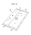
- an aseptic package 100 in accordance with the invention is shown in plan and perspective views respectively.
- the package 100 includes a first transverse seal 176, a second transverse seal 178, and a longitudinal seal 154.
- the package includes a first wall 129 having an outer surface 92 and an inner surface 91, corresponding to second surface 92 and first surface 91 of film 30.
- a fitment 39 is completely attached to the inner surface 91 of the first wall 129.
- First and second longitudinal ends 180 and 182 respectively of the package are defined by the outer longitudinal extremities of first transverse seal 176 and second transverse seal 178 respectively.
- some unsealed pouch material can be present between the outer longitudinal edge of a transverse seal, and the actual respective longitudinal edge of the pouch itself.
- the package 100 also includes a first lateral edge 184 and a second lateral edge 186. Edges 184 and 186 will typically be a fold, reflecting the tubular film from which the package was made in the VFFS process and apparatus.
- the package 100 contains a sterilized product.
- the package of the invention can be used in connection with any suitable dispensing tap, spout, dispensing pump, or other device for removal of sterilized product from the interior of the package by e.g. gravity or vacuum.
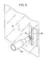
- FIG. 13 shows a side elevational partially cut away view of a system for dispensing a pumpable sterile product.
- the system 235 includes a product well 211 and a pump device 212.
- the package 216 (equivalent to package 100 of Figures 11 and 12 ) has been disposed in a generally U-shaped arrangement in product well 11 (shown in phantom here so that other features of the invention can be more clearly shown).
- the package can alternatively be placed in any suitable orientation, e.g. as would typically be used in bag-in-box or other commercial package configurations.
- fitment 39 is shown as centrally disposed in the package with respect to the first and second edges and first and second ends of the package, fitment 39 can be disposed at any convenient location on an interior surface of the package.
- the pump device 212 includes the cover 213, piston 214, and discharge tube 215 terminating in dispensing nozzle 217.
- the piston and discharge tube, along with the pump device body 238, are secured to the cover 213 by means of fastener 240.
- a drawing tube 242 on the lower portion of the pump device body terminates in a piercing nozzle 243.
- Piercing nozzle 243 is punched through the wall of package 243 in the vicinity of fitment 39 such that it inserts through orifice 52 of fitment 39 and communicates with the contained sterilized product 244.
- this piercing nozzle can be attached to a conventional drawing tube of a conventional pump device.
- Many alternative embodiments are possible, however, and any are suitable provided that a fitment 39 disposed on an internal surface of the pouch can be brought via piercing nozzle 243 into communication with a pump device.
- a contained sterilized product 244 such as a milk product, tomato product, or other pumpable food or non-food product, can thus be dispensed, upon activation of the pumping device by any suitable means such as mechanical or electromechanical means, through fitment 39, through piercing nozzle 243, up through drawing tube 242, up through pump device body 238, to discharge tube 215 and out through dispensing nozzle 217.
- Piercing nozzle 243 can be e.g. of the general type disclosed in the Stern patent ( U.S. Patent No. 4,603,793 ), referred to above, but can of any suitable configuration and geometry.
- An advantage of the particular fitment 39 disclosed in the drawings, is that the walls of the package will not totally collapse together in the area of the fitment, due to the geometry of the fitment. This, and the orifices present in the fitment, ensures that pumpable sterilized product will be able to flow through the fitment, and out through the pump device during emptying of the pouch by vacuum or gravity. This arrangement assures in many cases nearly complete emptying of the pouch.
- the system as shown in Figure 13 illustrates one of the walls of the package, namely first wall 129.
- Figure 14 shows a front elevational view of the system of Figure 13 .
- an external dispensing device is attached directly to the internal fitment 39 by piercing the package wall to access the sterilized contents of the package through internal fitment 39.
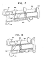
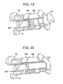
- an external fitment 302 can be employed for use in the invention. Examples are shown in Figures 5A , and 15 to 20. The wall of the package is shown in Figure 5A , but not shown in Figs. 15 to 20 .
- the external fitment can have any suitable configuration.
- external fitments 302 can be completely attached to the film at any suitable point in the aseptic packaging system and process, or alternatively can be partially attached at any suitable point in the aseptic packaging system and process, and can then be completely attached after they have advanced with film 141 over forming tube 144, but before the longitudinal heat seal has been made in the VFFS process.
- the external fitments, if employed, are installed on the second surface of the film, i.e. the surface that will ultimately form the outside of the aseptic package.
- the sterilization of external fitments 302 is therefore optional in many applications. Because of this, more freedom is available to install the external fitments at different points in the apparatus and process.
- the external fitments can be sealed to the second surface of the film upstream of the location in the system where the film is folded over the forming tube.
- the external fitments can be installed on the second surface of the film after the film has been unwound from a roll of film, and before the sterilization step.
- external fitments 302 can be installed on the film as or after it is made into a package. Attachment of the external fitments 302 to the film or package can be done by any suitable attaching or sealing device such as that described herein for attaching the internal fitments 39 to the film.
- the external fitments are each sealed to the second surface of the film by applying heat and pressure from a heat seal bar against the first surface of the film in the vicinity where each external fitment is to be attached to the film.
- Applying heat on the film side instead of on the fitment side is advantageous in more easily and securely attaching each fitment to the film. This also applies to the attachment of the internal fitment to the first surface of the film. It is advantageous to apply heat from the film side to attach each internal fitment to the first surface of the film.
- a fitment system 300 includes a sterilized internal fitment 39 attached to an interior sterilized surface of an aseptic package, as disclosed herein. Additionally, an external fitment 302 is attached to an exterior surface of the aseptic package, arranged so that the external fitment is disposed opposite the internal fitment, with the wall of the package between them.
- external fitment 302 includes an annular depression 304 that provides for a mechanical interlock with a dispensing device 306 (see Figure 16 ) having a ring 308 on one end thereof. Ring 308 is configured to mate with annular depression 304.
- Dispensing device 306 also includes a piercing nozzle 307, housing 309, and plunger 310.
- dispensing device 306 is mated with external fitment 302 by snapping ring 308 into annular depression 304 ( Figure 17 ).
- This step can be done at any time after manufacture of an aseptic package of the invention.
- plunger 310 in a first orientation, is pushed toward the package to force the piercing nozzle 307 through the package wall and through orifice 52 of fitment 39 (see Fig. 5 ).
- the plunger 310 is then retracted, and is ready to dispense product.
- product flows from the interior of the package, and is dispensed through dispensing device 306.
- dispensing devices can be used in connection with the present invention, and can be adapted to connect to an external fitment (if used) or directly to the internal fitment, by any suitable connection, such as that shown herein, or e.g. an interference fit or threaded connection.
- the dispensing device used can operate by vacuum or gravity feed.
- polymers such as polyester, polyamide, and polyolefin, refer herein to both homopolymers and copolymers thereof, unless otherwise specified.
- the film used in the manufacture of the package according to the invention can be made by any suitable process, including coextrusion, extrusion coating, extrusion lamination, and conventional lamination using polyurethane or other adhesives. These manufacturing processes are well known in the art. Extrusion can be done in annular or flat dies. The extrudate can be hot blown or cast, and optionally solid-state oriented as desired. Chemical or electronic crosslinking of one or more layers of the webs or the strip can be done. The film can be advanced through the system by suitable motive means (not shown, and well known in the art, such as a motor).
- Fitments can be made by any suitable process, e.g. injection molding.
- a package according to the invention can optionally carry printed indicia, which can be decorative or informational in nature.
- Decorative printed indicia can include a logo, a trademark, product information, etc. with text and/or graphics.
- the system, process, and package disclosed herein is suitable for both high and low acid products and combinations thereof.
- Films for use in the present invention can comprise a thermoplastic material of any suitable composition, including those having as at least one component olefinic material such as ethylene polymer or copolymer, e.g. polyethylene or ethylene/alpha olefin copolymer; and/or polyamide (nylon); and including films typically used in VFFS and/or aseptic packaging apparatus and processes.
- the films can be monolayer or multilayer in construction, can be coextruded, laminated, or made by any suitable film making process, and can have any suitable thickness.
- films useful in the invention include those with high oxygen barrier properties, and those with low oxygen barrier properties.
- Table 1 A representative multilayer film structure of some high oxygen barrier embodiments of the invention is shown in Table 1: Table 1 Material of layer G, or polyolefin Tie Nylon EVOH nylon Tie Amorphous material A B C D E F G
- Core layer D of the above film structure can comprise any suitable EVOH material, and can be blended in any proportion with other polymeric materials or organic or inorganic additives as desired.
- Intermediate layers C and E each comprise a polyamide, such as a semicrystalline polyamide such as nylon 6.
- layers C and E can each comprise a blend of an amorphous polyamide and a semicrystalline polyamide.
- the amorphous polyamide can comprise any suitable percent of the overall polyamide blend.
- the semicrystalline polyamide can be any suitable polyamide, including nylon 6.
- Tie layers B and F can comprise any suitable polymeric adhesive that functions to bond two layers together.
- Materials that can be used in embodiments of the present invention include anhydride grafted ethylene/alpha olefin copolymer.
- Layer A will typically function as a sealant layer of the film.
- This layer can comprise one or more semicrystalline olefinic polymers.
- Polymers that may be used for the layer A include ethylene polymer or copolymer, ethylene/alpha olefin copolymer, ethylene/vinyl acetate copolymer, ionomer resin, ethylene/ acrylic or methacrylic acid copolymer, ethylene/ acrylate or methacrylate copolymer, etc., or blends of any of these materials.
- layer A can comprise a material as defined herein for layer G.
- Layer G comprises one or more semicrystalline olefinic polymers, and/or an amorphous polymer e.g. amorphous cyclic olefin copolymer, e.g. ethylene/norbornene copolymer (ENB).
- layer G can comprise one outermost layer of the film such that when formed into a pouch, layer G comprises the layer furthest from the packaged product; and an olefinic polymer or copolymer such as ethylene/alpha olefin copolymer (EAO) can comprise the inner layer A of the film, such that when formed into a pouch, the EAO comprises the layer closest to the packaged product.
- the film can be lap sealed, for example a longitudinal lap seal running the length of the pouch, such that layer G is sealed to the EAO inner layer A. This embodiment provides a longitudinally lap sealed pouch.
- Table 2 A representative multilayer film structure of some low oxygen barrier embodiments of the invention is shown in Table 2: Table 2 Material of layer G, or polyolefin Tie Nylon Tie nylon Tie Amorphous material A B C D E F G
- the materials for film structures in accordance with table 2 can be as disclosed herein for table 1.
- Pouches made from the film of the present invention can be fin sealed or lap sealed (typically referring to the longitudinal seal running the length of the pouch) depending on the desired configuration of the finished pouch, the equipment used, and the composition of the two outer layers.
- Additional materials that can be incorporated into one or both of the outer layers of the film, and in other layers of the film as appropriate, include antiblock agents, slip agents, antifog agents, fillers, pigments, dyestuffs, antioxidants, stabilizers, processing aids, plasticizers, fire retardants, UV absorbers, etc. Additional film layers can be included either within the film structure, or adhered to an outer layer thereof.
- the film can have any total thickness desired, and each layer can have any thickness desired, so long as the film provides the desired properties for the particular packaging operation in which the film is used.
- Typical total thicknesses are from 0.013 to 0.38 mm (0.5 mils to 15 mils), such as 0.026 to 0.30 mm (1 mil to 12 mils), such as 0.051 to 0.25 mm (2 mils to 10 mils), 0.076 to 0.20 mm (3 mils to 8 mils), and 0.10 to 0.15 mm (4 mils to 6 mils).
- Film Example 1 represents a high oxygen barrier film
- Film Example 2 represents a low oxygen barrier film.
- Materials used are as shown in Table 3.
- Table 3 Resin Identification Material Code Tradename Or Designation Source(s) AB1 502835TM Ampacet PE1 ELITESTM 5400 G Dow PE2 DOWTM2045.04 Dow PE3 662ITM Dow PE4 T50-200-178TM Ineos AD1 PLEXARTM PX3236TM LyondellBasell Industries AD2 PX3410TM LyondellBasell Industries PA1 UL TRAMIDTMB40LN01 BASF OB1 EVALTM L171B Evalca EN1 TOPAS 8007 F-04TM Topas Advanced Polymers, Inc.
- AB1 is a masterbatch having about 80%, by weight of the masterbatch, of FORTIFLEXTM T60-500-119, a high density polyethylene with a density of 0.961 grams/cc; about 16%, by weight of the masterbatch, of SILTON JC30ATM, a sodium calcium aluminum silicate, NaCaAl(Si 2 O 7 ); and about 4 w%, by weight of the masterbatch, of CLEAR Block80TM talc, an antiblocking agent.
- PE1 is an IPN resin with a density of 0.917 grams/cc, and a melt flow index of 1.0.
- PE2 is an ethylene/octene-1 copolymer with a 6.5 weight % octene content, and a density of 0.920 grams/cc.
- PE3 is a low density polyethylene resin.
- PE4 is an ethylene/1-butene copolymer resin with a density of 0.952 grams/cc.
- AD1 is a maleic anhydride-modified linear low density polyethylene with a density of 0.921 grams/cc.
- AD2 is a maleic anhydride-modified linear low density polyethylene.
- PA1 is a nylon 6 (poly(caprolactam)).
- OB1 is an ethylene/vinyl alcohol copolymer with less than 30 mole% ethylene.
- EN1 is an ethylene/norbornene copolymer with a norbornene content of 36 mole % of the copolymer and a Tg of 80°C.
- Example 1 is a commercial product of the Cryovac business unit of Sealed Air Corporation.
Landscapes
- Engineering & Computer Science (AREA)
- Mechanical Engineering (AREA)
- Containers And Plastic Fillers For Packaging (AREA)
- Auxiliary Devices For And Details Of Packaging Control (AREA)
Claims (15)
- Système d'emballage aseptique (10) comprenant :a) un dispositif de déroulage de film (12) pour dérouler un film (30) à partir d'un premier rouleau de film (32) ;b) un dispositif d'alimentation en douilles (14) pour amener une pluralité de douilles (39) ;c) un appareil (16) pour fixer chacune des douilles (39) sur le film ;d) un ensemble (17) pour stériliser le film ;e) un ensemble (18) pour sécher le film ; etf) une formeuse-remplisseuse-scelleuse verticale (22) pour former une pluralité d'emballages (100) à partir du film stérilisé et de chacune des douilles stérilisées (39), chaque emballage (100) comprenantcaractérisé en ce que :i) un sachet stérilisé (149) comprenant(a) une première soudure transversale (176) à une première extrémité du sachet,(b) une deuxième soudure transversale (178) à une deuxième extrémité du sachet,(c) un premier pli (184) sur un premier côté du sachet,(d) une surface intérieure stérilisée (91),(e) une surface extérieure (92), et(f) une soudure longitudinale (154) s'étendant de la première extrémité du sachet à la deuxième extrémité du sachet ; et(g) une douille stérilisée (39) soudée sur le sachet ; etii) un produit stérilisé (244) placé dans le sachet ;la formeuse-remplisseuse-scelleuse verticale est configurée de telle manière que le sachet comprend en outre un deuxième pli (186) sur un deuxième côté du sachet, et de telle manière que la douille stérilisée (39) est une douille stérilisée interne soudée sur la surface intérieure stérilisée (91) du sachet ;l'ensemble (18) pour sécher le film comprend un ensemble (18) pour sécher le film et chacune des douilles (39) ; etl'ensemble (17) pour stériliser le film comprend un ensemble (17) pour stériliser le film et chacune des douilles (39).
- Système selon la revendication 1, dans lequel le dispositif d'alimentation en douilles (14) pour amener une pluralité de douilles comprend un élément orienteur (42) pour aligner la pluralité de douilles dans une direction prédéterminée, et un dispositif de guidage (44) pour guider chacune des douilles jusqu'à l'appareil servant à fixer chacune des douilles sur le film.
- Système selon la revendication 1, dans lequel chacune des douilles comprend une première bague annulaire (11), une deuxième bague (13) distante de la première bague, la deuxième bague étant connectée à ladite première bague annulaire au moyen d'une pluralité de jambes espacées (15), dans lequel les première et deuxième bagues sont planes et s'étendent parallèlement l'une à l'autre.
- Système selon la revendication 1, dans lequel l'appareil (16) pour fixer chacune des douilles sur le film comprend un appareil pour fixer partiellement chacune des douilles sur le film, et la formeuse-remplisseuse-scelleuse verticale (22) comprend un dispositif pour achever la fixation de chacune des douilles sur le film.
- Système selon la revendication 4, dans lequel l'appareil pour fixer partiellement chacune des douilles sur le film comprend un ensemble de soudage dans lequel une barre de soudage soude le film seulement sur une partie de la douille en deux régions de la douille, les deux régions étant espacées l'une de l'autre.
- Système selon la revendication 4, dans lequel l'appareil pour fixer partiellement chacune des douilles sur le film comprend un système de soudage dans lequel chacune des douilles comprend une première bague annulaire, et une deuxième bague distante de la première bague, et une barre de soudage soude le film seulement sur une partie de la première bague de la douille, en deux régions de la première bague, les deux régions étant espacées l'une de l'autre.
- Système selon la revendication 1, dans lequel l'ensemble (17) pour stériliser le film et chacune des douilles comprend un bain de peroxyde d'hydrogène.
- Système selon la revendication 1, dans lequel l'ensemble (18) pour sécher le film et chacune des douilles comprend une chambre de séchage, dans lequel la chambre de séchage comprend un dispositif tubulaire pour projeter de l'air stérile sur chacune des douilles tandis que chaque douille avance dans la chambre de séchage.
- Système selon la revendication 1, dans lequel l'ensemble (18) pour sécher le film et chacune des douilles comprend un mandrin fixe (207) placé en face de chaque douille, qui dévie le film pendant que chaque douille avance dans la chambre de séchage, ce qui provoque un éloignement du film par rapport aux parties non attachées de chaque douille pour faciliter le séchage de chaque douille.
- Système selon la revendication 4, dans lequel le dispositif pour achever la fixation de chacune des douilles sur le film comprend un ensemble de soudage dans lequel une barre de soudage achève la fixation de chacune des douilles partiellement fixées sur la première surface du film.
- Système selon la revendication 1, dans lequel une douille externe (302) est soudée sur la surface extérieure du sachet, en relation adjacente avec la douille interne.
- Système selon la revendication 1, dans lequel une douille externe stérilisée (302) est soudée sur la surface extérieure du sachet, en relation adjacente avec la douille interne.
- Procédé de fabrication d'un emballage aseptique (100) dans un processus de remplissage-scellage vertical comprenant :a) la fourniture d'un film aplati (30) sur un premier rouleau de film (32), le film aplati comprenant une première et une deuxième surface (91, 92) ;b) la fourniture d'une pluralité de douilles stérilisées (39) ;c) le déroulage du film depuis le premier rouleau de film ;d) l'avance du film jusqu'à un ensemble (17) pour stériliser le film ;e) la stérilisation du film ;f) l'avance du film stérilisé jusqu'à un ensemble (18) pour sécher le film ;g) le séchage du film ;h) l'avance du film stérilisé jusqu'à une formeuse-remplisseuse-scelleuse verticale (22) pour former une pluralité d'emballages à partir du film stérilisé ;i) l'avance du film stérilisé sur un dispositif de façonnage (144) pour convertir le film aplati en un film plié ayant une surface intérieure stérilisée ;j) la réalisation d'une soudure longitudinale (154) dans le film plié ;k) le soudage transversal du film plié pour produire une première soudure transversale (176) pour définir un premier sachet (149), dans lequel la première soudure transversale est une soudure transversale inférieure du premier sachet ;l) l'introduction d'un produit stérilisé (244) dans le premier sachet;m) l'avance du film plié, avec le premier sachet, vers le bas sur une distance prédéterminée ;n) le soudage transversal du premier sachet (149) pour produire un soudage transversal supérieur dans le premier sachet, et un soudage transversal inférieur dans un deuxième sachet (150), le deuxième sachet (150) étant placé au-dessus du premier sachet (149) ; eto) la découpe transversale du film plié pour séparer le premier sachet du deuxième sachet pour former un emballage (100), l'emballage comprenantcaractérisé en ce que :i) un sachet (149) comprenant(a) une première soudure transversale (176) à une première extrémité du sachet,(b) une deuxième soudure transversale (178) à une deuxième extrémité du sachet,(c) un premier pli (184) sur un premier côté du sachet,(d) une surface intérieure stérilisée (91),(e) une surface extérieure (92), et(f) une soudure longitudinale (154) s'étendant de la première extrémité du sachet à la deuxième extrémité du sachet ; et(g) une douille stérilisée (39) soudée au sachet ; etii) un produit stérilisé (244) placé dans le sachet ;le procédé comprend en outre, avant l'étape d'avance du film jusqu'à l'ensemble (17) pour stériliser et après le déroulage du film :i) l'avance du film aplati jusqu'à un appareil (16) pour fixer chacune des douilles sur le film ;ii) l'amenée de chacune des douilles depuis un dispositif d'alimentation en douilles (14) jusqu'à l'appareil pour fixer chacune des douilles sur le film ; etiii) la fixation de chacune des douilles sur la première surface du film ;en ce que l'ensemble (17) pour stériliser le film comprend un ensemble (17) pour stériliser le film et chacune des douilles ;en ce que l'avance du film jusqu'à l'ensemble (17) pour stériliser le film comprend l'avance du film, avec la pluralité de douilles fixées sur la première surface de celui-ci, jusqu'à l'ensemble (17) pour stériliser le film et chacune des douilles ;en ce que la stérilisation du film comprend la stérilisation de la première surface du film et de chacune des douilles ;en ce que l'ensemble (18) pour sécher le film comprend un ensemble (18) pour sécher le film et chacune des douilles ;en ce que l'avance du film stérilisé jusqu'à un ensemble (18) pour sécher le film comprend l'avance du film stérilisé, avec la pluralité de douilles stérilisées fixées sur la première surface de celui-ci, jusqu'à l'ensemble (18) pour sécher le film et chacune des douilles ;en ce que le séchage du film comprend le séchage de la première surface du film et de chacune des douilles ;en ce que la formeuse-remplisseuse-scelleuse verticale (22) pour former une pluralité d'emballages à partir du film stérilisé comprend une formeuse-remplisseuse-scelleuse verticale (22) pour former une pluralité d'emballages à partir du film stérilisé et de chacune des douilles stérilisées ;en ce que l'avance du film stérilisé jusqu'à la formeuse-remplisseuse-scelleuse verticale comprend l'avance du film stérilisé, avec une pluralité de douilles stérilisées fixées sur la première surface de celui-ci, jusqu'à la formeuse-remplisseuse-scelleuse verticale (22) pour former une pluralité d'emballages à partir du film stérilisé et de chacune des douilles stérilisées ;en ce que avant la réalisation d'une soudure longitudinale et après l'avance du film stérilisé sur le dispositif de façonnage, il y a une étape consistant à faire avancer chacune des douilles stérilisées avec le film de telle manière que lorsque l'emballage est fabriqué, la douille est disposée sur une paroi intérieure de l'emballage ; eten ce que le sachet comprend en outre un deuxième pli (186) sur un deuxième côté du sachet, et en ce que la douille stérilisée (39) est une douille stérilisée interne soudée sur la surface intérieure stérilisée (91) du sachet.
- Procédé selon la revendication 13 comprenant, dans l'étape de fixation, la fixation partielle de chacune des douilles sur la première surface du film ; et à n'importe quel moment après l'étape de fixation et avant l'étape de réalisation d'une soudure longitudinale, l'achèvement de la fixation de chaque douille sur le film.
- Emballage aseptique (100) comprenant :a) un sachet (149) comprenanti) une première soudure transversale (176) à une première extrémité du sachet,ii) une deuxième soudure transversale (178) à une deuxième extrémité du sachet,iii) un premier pli (184) sur un premier côté du sachet,iv) une surface intérieure stérilisée (91),v) une surface extérieure (92),vi) une soudure longitudinale (154) s'étendant de la première extrémité du sachet à la deuxième extrémité du sachet ; etvii) une douille stérilisée (39) fixée au sachet ; etb) un produit stérilisé (244) placé dans le sachet ;caractérisé en ce que le sachet comprend en outre un deuxième pli (186) sur un deuxième côté du sachet, et en ce que la douille stérilisée (39) est une douille interne stérilisée soudée sur la surface intérieure stérilisée (91) du sachet.
Applications Claiming Priority (2)
| Application Number | Priority Date | Filing Date | Title |
|---|---|---|---|
| US12/655,059 US8387348B2 (en) | 2009-12-22 | 2009-12-22 | Aseptic packaging system, packaging process and package with internal fitment |
| PCT/US2010/061045 WO2011087720A1 (fr) | 2009-12-22 | 2010-12-17 | Procédé et machine permettant de réaliser un emballage aseptique avec cloison interne, et emballage obtenu |
Publications (2)
| Publication Number | Publication Date |
|---|---|
| EP2516276A1 EP2516276A1 (fr) | 2012-10-31 |
| EP2516276B1 true EP2516276B1 (fr) | 2014-02-12 |
Family
ID=43735717
Family Applications (1)
| Application Number | Title | Priority Date | Filing Date |
|---|---|---|---|
| EP10807766.0A Not-in-force EP2516276B1 (fr) | 2009-12-22 | 2010-12-17 | Procede et machine pour fabriquer un emballage sterile muni d'un bec verseur interieur ainsi que l'emballage obtenu |
Country Status (8)
| Country | Link |
|---|---|
| US (1) | US8387348B2 (fr) |
| EP (1) | EP2516276B1 (fr) |
| AU (1) | AU2010341609B2 (fr) |
| IN (1) | IN2012DN04955A (fr) |
| MX (1) | MX2012006795A (fr) |
| NZ (1) | NZ600448A (fr) |
| RU (1) | RU2012124789A (fr) |
| WO (1) | WO2011087720A1 (fr) |
Families Citing this family (9)
| Publication number | Priority date | Publication date | Assignee | Title |
|---|---|---|---|---|
| DE102007015754B3 (de) * | 2007-03-30 | 2008-05-29 | Khs Ag | Anlage sowie Verfahren zum sterilen Verpacken von Produkten |
| SE533798C2 (sv) * | 2009-04-01 | 2011-01-18 | Tetra Laval Holdings & Finance | Säkerhetskammare som skall användas i en förpackningsmaskin |
| CN102387965B (zh) * | 2009-04-10 | 2013-07-17 | 织宽工程株式会社 | 无菌填充包装机和无菌填充包装方法 |
| EP2578505B1 (fr) * | 2011-10-03 | 2014-07-23 | Tetra Laval Holdings & Finance S.A. | Procédé de conditionnement et procédé pour produire des paquets étanches d'un produit alimentaire à partir d'une toile de matériau d'emballage |
| US20160009436A1 (en) * | 2014-07-14 | 2016-01-14 | Victor Basso | Machine for packing medical products and printing medical instructions for a nurse in a hospital environment |
| WO2016195675A1 (fr) * | 2015-06-03 | 2016-12-08 | Bemis Company, Inc. | Emballage pour indiquer une condition de scellement thermique |
| US11247410B2 (en) | 2016-12-02 | 2022-02-15 | Bemis Company, Inc. | Package for indicating heat-seal condition |
| EP3572221A4 (fr) * | 2017-01-18 | 2020-12-23 | Chokoku Plast Corporation | Procédé de production de film plissé et procédé de production de corps d'emballage plissé |
| ES2849473T3 (es) * | 2017-09-27 | 2021-08-18 | Tetra Laval Holdings & Finance | Aparato de envasado para formar envases sellados |
Family Cites Families (62)
| Publication number | Priority date | Publication date | Assignee | Title |
|---|---|---|---|---|
| US3246444A (en) * | 1962-08-09 | 1966-04-19 | T J Paisley Company | Method of forming a container having a shaker outlet |
| US3709437A (en) | 1968-09-23 | 1973-01-09 | Hershel Earl Wright | Method and device for producing foam |
| US3894381A (en) * | 1973-06-21 | 1975-07-15 | Inpaco | Method and means for attaching fitments to a bag or pouch on a packaging machine |
| US4184615A (en) | 1975-04-03 | 1980-01-22 | Wright Hershel E | Foam dispensing device |
| US4022351A (en) | 1975-04-03 | 1977-05-10 | Hershel Earl Wright | Foam dispenser |
| US3937364A (en) | 1975-04-03 | 1976-02-10 | Hershel Earl Wright | Foam dispensing device |
| US4147306A (en) | 1977-09-28 | 1979-04-03 | Bennett Robert S | Foam producing apparatus |
| JPS5675158A (en) * | 1979-11-27 | 1981-06-22 | Dainippon Printing Co Ltd | Sterilizer |
| SE445824B (sv) | 1980-01-10 | 1986-07-21 | Leif Einar Stern | Kopplingsanordning for anslutning av ett materialuttag till en forpackning |
| US4440316A (en) | 1980-02-27 | 1984-04-03 | Trinity Associates | Combined piercer and valve for flexible bag |
| US4516691A (en) | 1982-01-25 | 1985-05-14 | Trinity Foundation | Pierce turn tap |
| US4445550B1 (en) | 1982-08-20 | 1999-03-09 | Scholle Corp | Flexible walled container having membrane fitment for use with aseptic filling apparatus |
| US4598862A (en) | 1983-05-31 | 1986-07-08 | The Dow Chemical Company | Foam generating device and process |
| IT1171800B (it) * | 1983-11-14 | 1987-06-10 | Bieffe Spa | Sistema e apparecchiatura per la formatura ed il riempimento di sacche flessibili sterilizzabili |
| US4615467A (en) | 1985-07-24 | 1986-10-07 | Calmar, Inc. | Liquid foam dispenser |
| DE3612196A1 (de) * | 1986-04-11 | 1987-10-22 | Bosch Gmbh Robert | Vorrichtung zum herstellen von beutelpackungen mit entnahmestutzen |
| FR2604622B1 (fr) | 1986-10-06 | 1990-12-14 | Applied Chemical Research Corp | Composition liquide pour mousse a raser utilisable sans gaz propulseur dans un flacon en matiere plastique compressible |
| US4779397A (en) | 1987-03-09 | 1988-10-25 | Baxter Travenol Laboratories, Inc. | Apparatus and method for attaching a fitment to a web of film |
| AU7457191A (en) | 1990-03-27 | 1991-10-21 | Procter & Gamble Company, The | Foaming personal cleansing product with foam enhancing polymer |
| JPH0669161U (ja) | 1993-03-05 | 1994-09-27 | 大和製罐株式会社 | ポンプ式泡出し容器 |
| CA2169728C (fr) | 1993-08-18 | 2005-11-08 | William C. Christine | Appareil servant a former et a remplir un sac a cloison |
| US5467581A (en) | 1994-04-25 | 1995-11-21 | W. R. Grace & Co.-Conn. | Apparatus and process for positioning a fitment |
| US5645913A (en) | 1995-03-02 | 1997-07-08 | W. R. Grace & Co.-Conn. | Film and pouch with patch of high elongation |
| NL1001366C2 (nl) | 1995-10-06 | 1997-04-08 | Airspray Int Bv | Inrichting voor het afgeven van een luchtvloeistofmengsel, in het bijzonder schuim en daarvoor bestemde bedieningseenheid. |
| IT1285990B1 (it) * | 1996-11-22 | 1998-06-26 | Bieffe Medital Spa | Sistema per la formatura e il riempimento di sacche flessibili |
| US5915596A (en) * | 1997-09-09 | 1999-06-29 | The Coca-Cola Company | Disposable liquid containing and dispensing package and method for its manufacture |
| US6844387B2 (en) * | 1998-11-25 | 2005-01-18 | University Of Central Florida | Composites of inorganic luminophores stabilized in polymer hosts |
| US6244747B1 (en) | 1999-09-30 | 2001-06-12 | Cryovac, Inc. | Contoured pouch with pourable spout, and apparatus and process for producing same |
| BR0015575A (pt) | 1999-11-10 | 2003-07-22 | Scholle Corp | Recipiente dobravel para dosagem de lìquidos e método |
| IT1307523B1 (it) | 1999-12-02 | 2001-11-06 | Taplast Spa | Metodo di erogazione di liquidi sotto forma di schiuma tramitecontenitori deformabili e dispositivo utilizzante tale metodo |
| DE10102926A1 (de) * | 2001-01-23 | 2002-07-25 | Focke & Co | Verfahren zum Herstellen von Zigarettenpackungen |
| US6779318B2 (en) * | 2001-02-21 | 2004-08-24 | The Coca-Cola Company | System and method for continuously forming, sealing and filling flexible packages |
| US6668526B2 (en) | 2001-04-27 | 2003-12-30 | Baxter International, Inc. | Web centering system |
| US6718735B2 (en) | 2002-03-19 | 2004-04-13 | Baxter International Inc. | Albumin in a flexible polymeric container |
| ITMI20020839A1 (it) | 2002-04-19 | 2003-10-20 | Idealpack S R L | Sistema per l'estrazione di liquidi e creme con flusso regolare e continuo |
| BR0311469A (pt) | 2002-06-04 | 2005-03-15 | Rhodia | Composto de monÈmero que compreende diversos grupos catiÈnicos e polìmeros que compreendem unidades obtidas a partir deste |
| US20030223951A1 (en) | 2002-06-04 | 2003-12-04 | The Procter & Gamble Company | Conditioning shampoo compositions containing select cationic conditioning polymers |
| EP1551713A4 (fr) * | 2002-09-19 | 2007-12-05 | Afp Advanced Food Products Llc | Procede et appareil de production de tube fusionne sur un sac et sac ainsi produit |
| US6826892B2 (en) * | 2003-01-09 | 2004-12-07 | Glopak Inc. | Vertical form, fill and seal machine for handling large pouches |
| ITMI20030125A1 (it) | 2003-01-27 | 2004-07-28 | Giulio Ghisolfi | Sistema a fermaglio per corpi fogliformi, e relativi metodi di fabbricazione e di montaggio. |
| US20040254253A1 (en) | 2003-02-28 | 2004-12-16 | The Procter & Gamble Company | Foam-generating kit containing a foam-generating dispenser and a high viscosity composition |
| US8153108B2 (en) | 2003-04-25 | 2012-04-10 | Kao Corporation | Hair cosmetic product |
| US6860407B2 (en) * | 2003-05-05 | 2005-03-01 | Cryovac, Inc. | System and pouch for dispensing syrups, toppings, and other products |
| JP2005262202A (ja) | 2004-02-20 | 2005-09-29 | Yoshino Kogyosho Co Ltd | フォーマーディスペンサ |
| US7217033B2 (en) | 2004-05-13 | 2007-05-15 | Fres-Co System Usa, Inc. | Aseptic packaging for foods and systems and methods for aseptically packaging foods |
| WO2006135387A2 (fr) * | 2004-08-06 | 2006-12-21 | University Of Massachusetts | Points quantiques constitues de polymeres electroniquement actifs |
| US20060099167A1 (en) | 2004-11-05 | 2006-05-11 | Staudigel James A | Personal care composition containing a non-guar galactomannan polymer derivative |
| US7895811B2 (en) | 2004-11-23 | 2011-03-01 | Cryovac, Inc. | Apparatus and process for positioning a fitment |
| US8394474B2 (en) | 2005-04-07 | 2013-03-12 | Cryovac, Inc. | Sterilizable coextruded film for aseptic packaging |
| US20070025648A1 (en) | 2005-07-27 | 2007-02-01 | Kenneth Micnerski | Collapsible bag for dispensing liquids and method |
| US7495383B2 (en) * | 2005-08-01 | 2009-02-24 | Avago Technologies Ecbu Ip (Singapore) Pte. Ltd. | Phosphor based on a combination of quantum dot and conventional phosphors |
| US7513669B2 (en) * | 2005-08-01 | 2009-04-07 | Avago Technologies General Ip (Singapore) Pte. Ltd. | Light source for LCD back-lit displays |
| US20070110853A1 (en) | 2005-11-17 | 2007-05-17 | Solomon Bekele | Dimensionally stable sterilizable coextruded film for aseptic packaging |
| US9427391B2 (en) | 2006-01-09 | 2016-08-30 | The Procter & Gamble Company | Personal care compositions containing cationic synthetic copolymer and a detersive surfactant |
| US7594372B2 (en) | 2006-03-14 | 2009-09-29 | Scholle Corporation | Flexible container forming apparatus having integrated web surface deformation |
| US20070217718A1 (en) | 2006-03-14 | 2007-09-20 | Kenneth Micnerski | Collapsible bag for dispensing liquids and method |
| US20070263408A1 (en) * | 2006-05-09 | 2007-11-15 | Chua Janet Bee Y | Backlight module and method of making the module |
| JP4969940B2 (ja) * | 2006-07-31 | 2012-07-04 | 株式会社フジシールインターナショナル | スパウト装着方法 |
| BRPI0715343A2 (pt) | 2006-07-31 | 2013-06-18 | Liqui Box Canada Inc | conjunto de encaixe de perfuraÇço |
| US8211533B2 (en) | 2006-09-05 | 2012-07-03 | Liqui-Box Corporation | Resin blend of ethylene alpha olefin interpolymer and heterogeneous interpolymer for liquid packaging films |
| US20090123611A1 (en) | 2007-11-09 | 2009-05-14 | Cryovac, Inc. | Printed sterilizable laminate for aseptic packaging |
| US20110049442A1 (en) * | 2009-03-31 | 2011-03-03 | Schreuder Michael A | Surface structures for enhancement of quantum yield in broad spectrum emission nanocrystals |
-
2009
- 2009-12-22 US US12/655,059 patent/US8387348B2/en not_active Expired - Fee Related
-
2010
- 2010-12-17 EP EP10807766.0A patent/EP2516276B1/fr not_active Not-in-force
- 2010-12-17 NZ NZ600448A patent/NZ600448A/en not_active IP Right Cessation
- 2010-12-17 IN IN4955DEN2012 patent/IN2012DN04955A/en unknown
- 2010-12-17 AU AU2010341609A patent/AU2010341609B2/en not_active Ceased
- 2010-12-17 MX MX2012006795A patent/MX2012006795A/es not_active Application Discontinuation
- 2010-12-17 WO PCT/US2010/061045 patent/WO2011087720A1/fr active Application Filing
- 2010-12-17 RU RU2012124789/13A patent/RU2012124789A/ru not_active Application Discontinuation
Also Published As
| Publication number | Publication date |
|---|---|
| US20110146205A1 (en) | 2011-06-23 |
| IN2012DN04955A (fr) | 2015-09-25 |
| AU2010341609A1 (en) | 2012-06-21 |
| US8387348B2 (en) | 2013-03-05 |
| NZ600448A (en) | 2014-04-30 |
| AU2010341609B2 (en) | 2015-11-26 |
| MX2012006795A (es) | 2012-07-23 |
| WO2011087720A1 (fr) | 2011-07-21 |
| EP2516276A1 (fr) | 2012-10-31 |
| RU2012124789A (ru) | 2014-01-27 |
Similar Documents
| Publication | Publication Date | Title |
|---|---|---|
| EP2516276B1 (fr) | Procede et machine pour fabriquer un emballage sterile muni d'un bec verseur interieur ainsi que l'emballage obtenu | |
| AU2017258932B2 (en) | A bag-in-box system for use in dispensing a pumpable product. | |
| CN101754908B (zh) | 热收缩包装制品以及其制备方法 | |
| EP1499466B1 (fr) | Procédé pour former un récipient de fluide | |
| EP2516275B1 (fr) | Systeme et procede pour emballage aseptique ainsi que l'emballage obtenu avec douille exterieure | |
| US20040173492A1 (en) | Reclosable packages and method for forming, filling and sealing such packages | |
| CA2191092A1 (fr) | Lamines pour conditionnement par formage-remplissage-scellage | |
| CN112154057B (zh) | 制造容器的设备和方法 | |
| US20110097024A1 (en) | Easy Open Package with Discrete Panel Section with Die-Cut | |
| US20110097023A1 (en) | Easy Open Package with Discrete Laminate with Die-Cut | |
| AU2016250063B2 (en) | Method of positioning and sealing a bag in a vacuum chamber, bag positioning apparatus, and method of manufacturing a patch bag | |
| JP2007246122A (ja) | 蓋材 | |
| JP2004269053A (ja) | 熱収縮性包装 | |
| JP2007126216A (ja) | 折込部を有する密封袋及びその製造方法 | |
| JPH05270550A (ja) | 注出口を備えた液体収納袋およびその製造法ならびに前記収納袋に液体を充填する方法および装置 | |
| CN114555478B (zh) | 制袋填充方法以及制袋填充系统 | |
| SE455773B (sv) | Vermeforseglingsbart laminat innefattande pappers- och aluminiumskikt samt sett att framstella laminatet | |
| WO2016187176A1 (fr) | Emballage à bec verseur souple | |
| JP2022074015A (ja) | 包装袋 | |
| JP2004161348A (ja) | 包装充填方法、包装紙容器及び紙容器用積層包材 |
Legal Events
| Date | Code | Title | Description |
|---|---|---|---|
| PUAI | Public reference made under article 153(3) epc to a published international application that has entered the european phase |
Free format text: ORIGINAL CODE: 0009012 |
|
| 17P | Request for examination filed |
Effective date: 20120612 |
|
| AK | Designated contracting states |
Kind code of ref document: A1 Designated state(s): AL AT BE BG CH CY CZ DE DK EE ES FI FR GB GR HR HU IE IS IT LI LT LU LV MC MK MT NL NO PL PT RO RS SE SI SK SM TR |
|
| DAX | Request for extension of the european patent (deleted) | ||
| GRAP | Despatch of communication of intention to grant a patent |
Free format text: ORIGINAL CODE: EPIDOSNIGR1 |
|
| INTG | Intention to grant announced |
Effective date: 20130813 |
|
| RIN1 | Information on inventor provided before grant (corrected) |
Inventor name: MICNERSKI, KENNETH Inventor name: CAUDLE, TIMOTHY, G. |
|
| GRAS | Grant fee paid |
Free format text: ORIGINAL CODE: EPIDOSNIGR3 |
|
| GRAA | (expected) grant |
Free format text: ORIGINAL CODE: 0009210 |
|
| AK | Designated contracting states |
Kind code of ref document: B1 Designated state(s): AL AT BE BG CH CY CZ DE DK EE ES FI FR GB GR HR HU IE IS IT LI LT LU LV MC MK MT NL NO PL PT RO RS SE SI SK SM TR |
|
| REG | Reference to a national code |
Ref country code: GB Ref legal event code: FG4D |
|
| REG | Reference to a national code |
Ref country code: CH Ref legal event code: EP |
|
| REG | Reference to a national code |
Ref country code: AT Ref legal event code: REF Ref document number: 652037 Country of ref document: AT Kind code of ref document: T Effective date: 20140215 |
|
| REG | Reference to a national code |
Ref country code: IE Ref legal event code: FG4D |
|
| REG | Reference to a national code |
Ref country code: DE Ref legal event code: R096 Ref document number: 602010013584 Country of ref document: DE Effective date: 20140327 |
|
| REG | Reference to a national code |
Ref country code: NL Ref legal event code: T3 |
|
| REG | Reference to a national code |
Ref country code: AT Ref legal event code: MK05 Ref document number: 652037 Country of ref document: AT Kind code of ref document: T Effective date: 20140212 |
|
| REG | Reference to a national code |
Ref country code: LT Ref legal event code: MG4D |
|
| PG25 | Lapsed in a contracting state [announced via postgrant information from national office to epo] |
Ref country code: LT Free format text: LAPSE BECAUSE OF FAILURE TO SUBMIT A TRANSLATION OF THE DESCRIPTION OR TO PAY THE FEE WITHIN THE PRESCRIBED TIME-LIMIT Effective date: 20140212 Ref country code: NO Free format text: LAPSE BECAUSE OF FAILURE TO SUBMIT A TRANSLATION OF THE DESCRIPTION OR TO PAY THE FEE WITHIN THE PRESCRIBED TIME-LIMIT Effective date: 20140512 Ref country code: IS Free format text: LAPSE BECAUSE OF FAILURE TO SUBMIT A TRANSLATION OF THE DESCRIPTION OR TO PAY THE FEE WITHIN THE PRESCRIBED TIME-LIMIT Effective date: 20140612 |
|
| PG25 | Lapsed in a contracting state [announced via postgrant information from national office to epo] |
Ref country code: AT Free format text: LAPSE BECAUSE OF FAILURE TO SUBMIT A TRANSLATION OF THE DESCRIPTION OR TO PAY THE FEE WITHIN THE PRESCRIBED TIME-LIMIT Effective date: 20140212 Ref country code: SE Free format text: LAPSE BECAUSE OF FAILURE TO SUBMIT A TRANSLATION OF THE DESCRIPTION OR TO PAY THE FEE WITHIN THE PRESCRIBED TIME-LIMIT Effective date: 20140212 Ref country code: CY Free format text: LAPSE BECAUSE OF FAILURE TO SUBMIT A TRANSLATION OF THE DESCRIPTION OR TO PAY THE FEE WITHIN THE PRESCRIBED TIME-LIMIT Effective date: 20140212 Ref country code: ES Free format text: LAPSE BECAUSE OF FAILURE TO SUBMIT A TRANSLATION OF THE DESCRIPTION OR TO PAY THE FEE WITHIN THE PRESCRIBED TIME-LIMIT Effective date: 20140212 Ref country code: FI Free format text: LAPSE BECAUSE OF FAILURE TO SUBMIT A TRANSLATION OF THE DESCRIPTION OR TO PAY THE FEE WITHIN THE PRESCRIBED TIME-LIMIT Effective date: 20140212 Ref country code: PT Free format text: LAPSE BECAUSE OF FAILURE TO SUBMIT A TRANSLATION OF THE DESCRIPTION OR TO PAY THE FEE WITHIN THE PRESCRIBED TIME-LIMIT Effective date: 20140612 |
|
| PG25 | Lapsed in a contracting state [announced via postgrant information from national office to epo] |
Ref country code: RS Free format text: LAPSE BECAUSE OF FAILURE TO SUBMIT A TRANSLATION OF THE DESCRIPTION OR TO PAY THE FEE WITHIN THE PRESCRIBED TIME-LIMIT Effective date: 20140212 Ref country code: HR Free format text: LAPSE BECAUSE OF FAILURE TO SUBMIT A TRANSLATION OF THE DESCRIPTION OR TO PAY THE FEE WITHIN THE PRESCRIBED TIME-LIMIT Effective date: 20140212 Ref country code: BE Free format text: LAPSE BECAUSE OF FAILURE TO SUBMIT A TRANSLATION OF THE DESCRIPTION OR TO PAY THE FEE WITHIN THE PRESCRIBED TIME-LIMIT Effective date: 20140212 Ref country code: LV Free format text: LAPSE BECAUSE OF FAILURE TO SUBMIT A TRANSLATION OF THE DESCRIPTION OR TO PAY THE FEE WITHIN THE PRESCRIBED TIME-LIMIT Effective date: 20140212 |
|
| PG25 | Lapsed in a contracting state [announced via postgrant information from national office to epo] |
Ref country code: RO Free format text: LAPSE BECAUSE OF FAILURE TO SUBMIT A TRANSLATION OF THE DESCRIPTION OR TO PAY THE FEE WITHIN THE PRESCRIBED TIME-LIMIT Effective date: 20140212 Ref country code: EE Free format text: LAPSE BECAUSE OF FAILURE TO SUBMIT A TRANSLATION OF THE DESCRIPTION OR TO PAY THE FEE WITHIN THE PRESCRIBED TIME-LIMIT Effective date: 20140212 Ref country code: DK Free format text: LAPSE BECAUSE OF FAILURE TO SUBMIT A TRANSLATION OF THE DESCRIPTION OR TO PAY THE FEE WITHIN THE PRESCRIBED TIME-LIMIT Effective date: 20140212 Ref country code: CZ Free format text: LAPSE BECAUSE OF FAILURE TO SUBMIT A TRANSLATION OF THE DESCRIPTION OR TO PAY THE FEE WITHIN THE PRESCRIBED TIME-LIMIT Effective date: 20140212 |
|
| REG | Reference to a national code |
Ref country code: DE Ref legal event code: R097 Ref document number: 602010013584 Country of ref document: DE |
|
| PG25 | Lapsed in a contracting state [announced via postgrant information from national office to epo] |
Ref country code: SK Free format text: LAPSE BECAUSE OF FAILURE TO SUBMIT A TRANSLATION OF THE DESCRIPTION OR TO PAY THE FEE WITHIN THE PRESCRIBED TIME-LIMIT Effective date: 20140212 Ref country code: PL Free format text: LAPSE BECAUSE OF FAILURE TO SUBMIT A TRANSLATION OF THE DESCRIPTION OR TO PAY THE FEE WITHIN THE PRESCRIBED TIME-LIMIT Effective date: 20140212 |
|
| PLBE | No opposition filed within time limit |
Free format text: ORIGINAL CODE: 0009261 |
|
| STAA | Information on the status of an ep patent application or granted ep patent |
Free format text: STATUS: NO OPPOSITION FILED WITHIN TIME LIMIT |
|
| 26N | No opposition filed |
Effective date: 20141113 |
|
| REG | Reference to a national code |
Ref country code: DE Ref legal event code: R097 Ref document number: 602010013584 Country of ref document: DE Effective date: 20141113 |
|
| PG25 | Lapsed in a contracting state [announced via postgrant information from national office to epo] |
Ref country code: IT Free format text: LAPSE BECAUSE OF FAILURE TO SUBMIT A TRANSLATION OF THE DESCRIPTION OR TO PAY THE FEE WITHIN THE PRESCRIBED TIME-LIMIT Effective date: 20140212 |
|
| PG25 | Lapsed in a contracting state [announced via postgrant information from national office to epo] |
Ref country code: SI Free format text: LAPSE BECAUSE OF FAILURE TO SUBMIT A TRANSLATION OF THE DESCRIPTION OR TO PAY THE FEE WITHIN THE PRESCRIBED TIME-LIMIT Effective date: 20140212 |
|
| PG25 | Lapsed in a contracting state [announced via postgrant information from national office to epo] |
Ref country code: LU Free format text: LAPSE BECAUSE OF FAILURE TO SUBMIT A TRANSLATION OF THE DESCRIPTION OR TO PAY THE FEE WITHIN THE PRESCRIBED TIME-LIMIT Effective date: 20141217 |
|
| REG | Reference to a national code |
Ref country code: CH Ref legal event code: PL |
|
| REG | Reference to a national code |
Ref country code: IE Ref legal event code: MM4A |
|
| PG25 | Lapsed in a contracting state [announced via postgrant information from national office to epo] |
Ref country code: LI Free format text: LAPSE BECAUSE OF NON-PAYMENT OF DUE FEES Effective date: 20141231 Ref country code: IE Free format text: LAPSE BECAUSE OF NON-PAYMENT OF DUE FEES Effective date: 20141217 Ref country code: CH Free format text: LAPSE BECAUSE OF NON-PAYMENT OF DUE FEES Effective date: 20141231 |
|
| REG | Reference to a national code |
Ref country code: FR Ref legal event code: PLFP Year of fee payment: 6 |
|
| PG25 | Lapsed in a contracting state [announced via postgrant information from national office to epo] |
Ref country code: SM Free format text: LAPSE BECAUSE OF FAILURE TO SUBMIT A TRANSLATION OF THE DESCRIPTION OR TO PAY THE FEE WITHIN THE PRESCRIBED TIME-LIMIT Effective date: 20140212 |
|
| PG25 | Lapsed in a contracting state [announced via postgrant information from national office to epo] |
Ref country code: MC Free format text: LAPSE BECAUSE OF FAILURE TO SUBMIT A TRANSLATION OF THE DESCRIPTION OR TO PAY THE FEE WITHIN THE PRESCRIBED TIME-LIMIT Effective date: 20140212 |
|
| PG25 | Lapsed in a contracting state [announced via postgrant information from national office to epo] |
Ref country code: BG Free format text: LAPSE BECAUSE OF FAILURE TO SUBMIT A TRANSLATION OF THE DESCRIPTION OR TO PAY THE FEE WITHIN THE PRESCRIBED TIME-LIMIT Effective date: 20140212 Ref country code: GR Free format text: LAPSE BECAUSE OF FAILURE TO SUBMIT A TRANSLATION OF THE DESCRIPTION OR TO PAY THE FEE WITHIN THE PRESCRIBED TIME-LIMIT Effective date: 20140513 |
|
| PG25 | Lapsed in a contracting state [announced via postgrant information from national office to epo] |
Ref country code: TR Free format text: LAPSE BECAUSE OF FAILURE TO SUBMIT A TRANSLATION OF THE DESCRIPTION OR TO PAY THE FEE WITHIN THE PRESCRIBED TIME-LIMIT Effective date: 20140212 Ref country code: MT Free format text: LAPSE BECAUSE OF FAILURE TO SUBMIT A TRANSLATION OF THE DESCRIPTION OR TO PAY THE FEE WITHIN THE PRESCRIBED TIME-LIMIT Effective date: 20140212 Ref country code: HU Free format text: LAPSE BECAUSE OF FAILURE TO SUBMIT A TRANSLATION OF THE DESCRIPTION OR TO PAY THE FEE WITHIN THE PRESCRIBED TIME-LIMIT; INVALID AB INITIO Effective date: 20101217 |
|
| REG | Reference to a national code |
Ref country code: FR Ref legal event code: PLFP Year of fee payment: 7 |
|
| REG | Reference to a national code |
Ref country code: FR Ref legal event code: PLFP Year of fee payment: 8 |
|
| PGFP | Annual fee paid to national office [announced via postgrant information from national office to epo] |
Ref country code: NL Payment date: 20171226 Year of fee payment: 8 Ref country code: FR Payment date: 20171227 Year of fee payment: 8 |
|
| PGFP | Annual fee paid to national office [announced via postgrant information from national office to epo] |
Ref country code: GB Payment date: 20171227 Year of fee payment: 8 |
|
| PGFP | Annual fee paid to national office [announced via postgrant information from national office to epo] |
Ref country code: DE Payment date: 20171229 Year of fee payment: 8 |
|
| PG25 | Lapsed in a contracting state [announced via postgrant information from national office to epo] |
Ref country code: MK Free format text: LAPSE BECAUSE OF FAILURE TO SUBMIT A TRANSLATION OF THE DESCRIPTION OR TO PAY THE FEE WITHIN THE PRESCRIBED TIME-LIMIT Effective date: 20140212 |
|
| PG25 | Lapsed in a contracting state [announced via postgrant information from national office to epo] |
Ref country code: AL Free format text: LAPSE BECAUSE OF FAILURE TO SUBMIT A TRANSLATION OF THE DESCRIPTION OR TO PAY THE FEE WITHIN THE PRESCRIBED TIME-LIMIT Effective date: 20140212 |
|
| REG | Reference to a national code |
Ref country code: DE Ref legal event code: R119 Ref document number: 602010013584 Country of ref document: DE |
|
| REG | Reference to a national code |
Ref country code: NL Ref legal event code: MM Effective date: 20190101 |
|
| GBPC | Gb: european patent ceased through non-payment of renewal fee |
Effective date: 20181217 |
|
| PG25 | Lapsed in a contracting state [announced via postgrant information from national office to epo] |
Ref country code: NL Free format text: LAPSE BECAUSE OF NON-PAYMENT OF DUE FEES Effective date: 20190101 |
|
| PG25 | Lapsed in a contracting state [announced via postgrant information from national office to epo] |
Ref country code: DE Free format text: LAPSE BECAUSE OF NON-PAYMENT OF DUE FEES Effective date: 20190702 Ref country code: FR Free format text: LAPSE BECAUSE OF NON-PAYMENT OF DUE FEES Effective date: 20181231 |
|
| PG25 | Lapsed in a contracting state [announced via postgrant information from national office to epo] |
Ref country code: GB Free format text: LAPSE BECAUSE OF NON-PAYMENT OF DUE FEES Effective date: 20181217 |