EP2513704B1 - Imaging device and method - Google Patents
Imaging device and method Download PDFInfo
- Publication number
- EP2513704B1 EP2513704B1 EP10752464.7A EP10752464A EP2513704B1 EP 2513704 B1 EP2513704 B1 EP 2513704B1 EP 10752464 A EP10752464 A EP 10752464A EP 2513704 B1 EP2513704 B1 EP 2513704B1
- Authority
- EP
- European Patent Office
- Prior art keywords
- image
- strobe light
- projection surface
- guest
- transparent projection
- Prior art date
- Legal status (The legal status is an assumption and is not a legal conclusion. Google has not performed a legal analysis and makes no representation as to the accuracy of the status listed.)
- Active
Links
Images


Classifications
-
- G—PHYSICS
- G09—EDUCATION; CRYPTOGRAPHY; DISPLAY; ADVERTISING; SEALS
- G09F—DISPLAYING; ADVERTISING; SIGNS; LABELS OR NAME-PLATES; SEALS
- G09F19/00—Advertising or display means not otherwise provided for
- G09F19/12—Advertising or display means not otherwise provided for using special optical effects
- G09F19/18—Advertising or display means not otherwise provided for using special optical effects involving the use of optical projection means, e.g. projection of images on clouds
-
- G—PHYSICS
- G02—OPTICS
- G02B—OPTICAL ELEMENTS, SYSTEMS OR APPARATUS
- G02B30/00—Optical systems or apparatus for producing three-dimensional [3D] effects, e.g. stereoscopic images
- G02B30/40—Optical systems or apparatus for producing three-dimensional [3D] effects, e.g. stereoscopic images giving the observer of a single two-dimensional [2D] image a perception of depth
Definitions
- the present invention relates to theme park attractions. More particularly, the present invention relates to an image projecting device and method for creating physiological illusions in a viewing guest.
- Physiological illusions are effects on the eyes or brain of excessive stimulation of a specific type such as brightness, tilt, color, and movement.
- the theory is that stimuli have individual dedicated neural paths in the early stages of visual processing, and that repetitive stimulation of only one or a few channels causes a physiological imbalance that alters perception.
- Physiological illusions generally include afterimages following bright lights or adapting stimuli of excessively longer alternating patterns.
- the excitation is processed by the neuronal system and various parts of the brain working in parallel to form a representation of the external environment in the brain.
- the cones respond to bright light and mediate high-resolution vision and color vision.
- the rods respond to dim light and mediate lower-resolution, black- and-white, and night vision.
- the receptors are also 'cross-linked' by horizontal cells and amacrine cells, which modify the synaptic signal before the ganglion cells.
- Rod and cone signals are intermixed and combine, although rods are mostly active in very poorly lit conditions and saturate in broad daylight, while cones function in brighter lighting because they are not sensitive enough to work at very low light levels.
- After-imaging is an optical illusion that refers to an image continuing to appear in one's vision after the exposure to the original image has ceased.
- One of the most common afterimages is the bright glow that seems to float before one's eyes after staring at a light bulb or a headlight for a few seconds.
- the phenomenon of afterimages may be closely related to persistence of vision, which allows a rapid series of pictures to portray motion, which is the basis of animation and cinema.
- Negative after-images come in two forms, negative (inverted) and positive (retaining original color).
- Negative after-images are a retinal phenomenon and are well understood. Negative after-images are caused when the eye's photoreceptors, primarily those known as cone cells, adapt from the over stimulation and lose sensitivity. Normally the eye deals with this problem by rapidly moving the eye small amounts, the motion later being "filtered out” so it is not noticeable. However if the color image is large enough that the small movements are not enough to change the color under one area of the retina, those cones will eventually tire or adapt and stop responding. The rod cells can also be affected by this.
- Positive afterimages are less understood. Generally, they appear the same color as the original image. They are often very brief, lasting less than half a second, and may not occur unless the stimulus is very bright. The cause of positive after-images is not well known, but possibly reflects persisting activity in the visual system where the retinal photoreceptor cells continue to send neural impulses to the occipital lobe, suggesting that the experience of a stimulus can vary with the intensity of the stimulus. Only very bright stimuli produce positive afterimages, and a stimulus which elicits a positive image will usually trigger a negative afterimage quickly via the adaptation process.
- USP 5,407,391 describes a negative bust illusion formed from a surface that presents a concave side to viewers to generate an illusion that the object always gazes at viewers as they move within an enlarged field of view.
- USP 5,650,815 describes a method and apparatus for creating an illusion of depth when viewing moving pictures projected on a plane surface. Glasses to worn by a viewer when viewing the moving pictures have the property of altering or distorting the real image projected. The disparity between the apparent images viewed by the two eyes creates an image disparity that is interpreted as a perception of depth.
- the glasses incorporate a lens for the dominant eye and a lens for the docile eye which narrows the image along the visual plane and the lens for the docile eye broadens the image along the visual plane.
- the lens for each eye is appropriately tinted to enhance the perception of depth.
- the glasses are reversible to enable placing the desired lens in front of the dominant and thus the docile eye.
- JP 5040448A describes a continuous motion device which comprises a large number of screen boxes for continuous action video which are arranged on the wall plane of a theatre tunnel observed from the window of a mobile body keeping a prescribed interval.
- the still picture for continuous action is mounted on a base plate located at a part where it can be peeped from the glass window of a screen box main body.
- the shutter mechanism using one or more flash lights such as stroboscopic lights or flash lights, etc., which in a moment illuminate or unilluminate the still picture for continuous action mounted on the screen box main body is mounted. Since the still picture can be illuminated or unilluminated in a moment with the flash light, the after-image effect can be generated, which enables the still picture to be observed as the continuous action video.
- JP 2000 172221A describes a video display device has plural sets of display devices arranged at places where can be seen from a mobile object running while carrying persons in one line state at prescribed intervals, a still video signal storage means for supplying still video signals to the display devices, a control means for controlling the still video signal storage means, a detecting sensor for detecting that the mobile object is positioned at the places where the display devices are installed, and an illuminator for display the plural display devices intermittently.
- Still video signals consisting of plural programs different in contents are stored in the storage means. Then, programs are successively selected by the control of the control means and still video signals corresponding to the selected are supplied to the display devices.
- plural videos different in contents are displayed on the devices by being switched at every time, for example, a train run by electricity passes by this video display device.
- past imaging devices do not create perceived images that are physiological in nature only, nor do past imaging devices and do not sufficiently utilize positive or negative after-imaging.
- the present disclosure describes an image projecting device and method for producing a physiological illusion in a viewing guest device.
- an image projecting device for producing a physiological illusion in a viewing guest as described in accompanying Claim 1.
- One embodiment of the present invention involves an image projecting device for producing a physiological in a viewing guest comprising a transparent projection surface and a strobe light configured to illuminate an image on the transparent projection surface.
- a particular advantages afforded by this invention is the ability to create a new experience for a guest and thus increase theme park attendance.
- One embodiment of the present invention relates to image projecting device for producing a physiological illusion in a viewing guest.
- the device may be incorporated into rides or shows.
- the device may be applicable to roller coasters in the dark, scramblers in the dark, or theme based rides having vehicles that reside on tracks, such as to take guests though a haunted house.
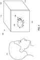
- the image projecting device may include a housing 102 having a transparent projection surface 104, a strobe light (i.e., stroboscopic lamp) 106, and an image 108.
- a strobe light i.e., stroboscopic lamp
- the housing 102 is enclosed on all sides by left wall 112, top 114, back (not shown) and right wall (not shown). This way, the interior of the housing 102 is a light deficient environment with the exception of the transparent projection surface 104, the housing being configured to thereby concentrate light through the transparent projection surface when the strobe 106 is activated.
- the housing 102 may be constructed of any material suitably strong and durable such as plastic, steel or wood.
- the exterior of the housing 102 may comprise appropriate braces, brackets or notches (not shown) to secure the device 100 to a desired object.
- the interior of the housing 102 may also comprise appropriate braces, brackets or notches for attaching the strobe 106, which is supported by the housing 102.
- the strobe light 106 may be mounted or fixed to a back side of the interior of the housing 102, as shown in Figure 2 , or it may be mounted or fixed to a bottom panel of the interior of the housing 102.
- the strobe light 106 may be commercial strobe light having a flash energy of approximately 10 to 150 joules with a discharge time of approximately 2 or 3 milliseconds thereby creating powerful illumination.
- the strobe light may range in value from 50 watts to 800 watts or greater.
- the light source as is known in the art, may be a xenon flash lamp. If colored lights are desirable, strobe specific gels may be used, as is known in the art.
- the strobe light 106 may be configured to activate at a predetermined time, when guest 110 is in viewing range.
- the imaging projecting device is shown generally at reference numeral 200.
- the image projecting device may include a housing 102 having a transparent projection surface 104, a strobe light 106, an image 108, a controller 202 and central processor 204.
- the controller 202 is configured to activate and set duration of the strobe light 106 at a predetermined time to produce a physiological illusion of the image in the viewing guest 110.
- the controller may be an integrated circuit able to process command signals from a central processor 204.
- the controller 204 may be electrically connected to the strobe light 106 via line 206 through the stabilization block 208.
- the controller 202 may be further connected to the transparent projection surface 104 via line 208, the projection surface to be discussed in greater detail with relation to Figures 3a and 3b .
- the controller 202 may also be electrically connected and in communication with the central processor 204 which may comprise a power source 212.
- the controller 202 is configured to activate the strobe 106 at a predetermined time. For example, if a guest 110 is on a ride vehicle on tracks (e.g., a rollercoaster in the dark), the central processor 204 may communicate ride vehicle position through a plurality of track or vehicle sensors which may also be in communication with the central processor 204. The central processor may then, at a predetermined time, send a command signal to the controller 202 which may activate the strobe light 106 when a guest is in the appropriate viewing position. Furthermore, the central processor 204 may send command signals to the controller 202 to control the duration of the strobe light 106. In this embodiment, duration of the strobe light 106 may correspond to ride vehicle speed.
- the speed of the vehicle may be relatively fast. Therefore, to produce the desired effect of a physiological illusion, the strobe duration may be relatively high when compared to an attraction in which the guest is moving into the projectors field of view at slower speeds.
- the image projecting device may include a housing 102 having a transparent projection surface 104, and strobe light 106.
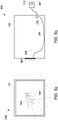
- the transparent projection surface 104 may comprise a first ply 302 and a second ply 304 to form a gap 306 for insertion of an imaging plate 308.
- Each of the plies 302 and 304 are transparent so as to allow maximum light penetration and to be free from obscurities or dimming.
- the transparent projection surface 104 may be manufactured from a suitably strong and scratch resistant plastics or coated with abrasion resistant coating.
- the plies 302 and 304 must be durable enough to hold imaging plate 308 in gap 304 in a manner which prevents the plate 308 from shifting.
- the transparent projection surface also includes a stabilization member 310 to support the imaging plate 308.
- Imaging plate 312 comprises a negative image 316.
- negative image it is meant that the image itself is light transparent, while the rest of the imaging plate is light resistant.
- a negative imaging plate such as 312 concentrates light from the strobe 106 to produce a physiological illusion on the retina of a viewing guest.
- the imaging plate 314 comprises a positive image 318.
- positive image it is meant that the entire imaging plate is transparent with the exception of a silhouette of the image.
- the imaging plates 312 and 314, like the transparent projection surface, may be manufactured from a suitably strong and scratch resistant plastic or coated with abrasion resistant coating.
- the transparent projection surface 104 may comprise an opaque inverse cutout of an object, held in place by a vice (not shown) at a lower portion of the cutout.
- the images on imaging plates 312 and 314 is a pig
- the image may also comprise a deer, a human face, a tree, a building, or any desirable object corresponding to a theme of a ride for use with the present invention.
- the image may comprise a forbidding creature such as a murderous clown or a ghoul.
- the image may be changeable by an operator, by for example, sliding different plates of the plurality of plates between the plies.
- the plates may be changed automatically by a slide real.
- the image may be etched or painted on the imaging plates 312 and 314 by known techniques.
- the translucent projection surface may comprise a transparent LCD monitor.
- the projection assembly of this example comprises a housing 102 having a transparent projection surface 104, a strobe light (i.e., stroboscopic lamp) 106, and an image 108.
- an LCD monitor 402 functions as the transparent projection surface 104.
- the LCD may be configured so as to not allow light to penetrate the screen, except in a shape corresponding to a desired object.
- the controller 202 may be electrically connected to the strobe light 106 via line 206.
- the controller 202 may be further connected to the transparent projection surface 104 via lines 208.
- the controller 202 may also be electrically connected and in communication with the central processor 204 which may comprise a power source 212.
- the controller 202 may be configured to activate the strobe light 106 at a predetermined time.
- the controller 202 in this example may also be configured to automatically generate the image 402 located on the LCD screen when prompted by the central processor 204.
- the central processor 204 may then, at a predetermined time, send a command signal to the controller 202 which may activate the strobe light 106 when the desired image is displayed.
- a guest who is in a stationary ride may enjoy a plurality of different images through the use of only one image projecting device 400.
- the device may be incorporated into the show at predetermined intervals.
- the central processor 204 may communicate with the controller and at a predetermined time display a first image. Then, later in the ride, the central processor may send a different command to the processor to display a second image, and so on.
- the images displayed on the LCD monitor 402 may in this example, as discussed with regard to Figure 3b , be positive or negative images.
- the LCD monitor 402 may be an electronically modulated optical monitor with monochrome pixels that may, when activated allow or disallow the light from the strobe 106 to pass through its face. For example, if the image is to be negative, the pixels would active as black except for the shape of the area 404 or 406 to produce the image. If the image positive, the pixels would form only the silhouettes of images 404 or 406. The strobe 106 will then activate at a corresponding time to thereby produce a physiological illusion to a guest.
- the guest may be in dark or dimly lit environment when the projecting device is activated. If a guest, either stationary viewing or passing by, is subject to the strobe flashing through or around on image, once the image disappears in reality, it will still be viewable by the guest as an "after-image".
- the strobe 106 flashes the cones and rods of the retina become stimulated. Because the strobe flashes at a speed of one flash per three milliseconds at least, cone cells adapt from the over stimulation and lose sensitivity thus producing an after image.
- a positive after-image may also be produced by the strobe because after the image flashes, the guest remains in a dark area. The guest should see a fading positive afterimage, likely followed by a negative afterimage that may last longer.
- the strobe may comprise an array of ultra-bright light emitting diodes (hereinafter "LEDs") 504 configured in a desirable shapes or patterns such as those described above.
- LEDs 504 may include a size of 2-10mm.
- the LEDs 504 may be connected to a controller 202, which may be configured to activate and set duration of the strobe light 106 at a predetermined time to produce a physiological illusion of the image in the viewing guest.
- the controller 204 may be electrically connected to the array of LEDs 504 via line 206 through the circuit board 506.
- the controller 202 may be further connected to the transparent projection surface 104 via line 208.
- the controller 202 may also be electrically connected and in communication with the central processor 204 which may comprise a power source 212.
- the controller 202 may be configured to activate the array of light emitting diodes 504 at a predetermined time. For example, if a guest 110 is on a ride vehicle on tracks (e.g., a rollercoaster in the dark), the central processor 204 may communicate ride vehicle position through a plurality of track or vehicle sensors which may also be in communication with the central processor 204. The central processor may then, at a predetermined time, send a command signal to the controller 202 which may activate the array of light emitting diodes 504 when a guest is in the appropriate viewing position. Furthermore, the central processor 204 may send command signals to the controller 202 to control the duration and which LEDs on the screen may become lit.
- a predetermined time For example, if a guest 110 is on a ride vehicle on tracks (e.g., a rollercoaster in the dark), the central processor 204 may communicate ride vehicle position through a plurality of track or vehicle sensors which may also be in communication with the central processor 204. The central processor may then, at a predetermined
- duration of the strobe light 106 may correspond to ride vehicle speed.
- the speed of the vehicle may be relatively fast. Therefore, to produce the desired effect of a physiological illusion, the LED duration may be relatively high when compared to an attraction in which the guest is moving into the projectors field of view at slower speeds.
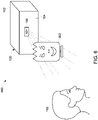
- a system for producing a physiological illusion in a viewing guest is provided at 600.
- the system may comprise a projection device 100 having a housing 102, the housing 102 having a transparent projection surface 104, a strobe light 106 supported by the housing 102; and an opaque object 602 proximate the transparent projection surface; wherein the opaque object 602 defines a negative or positive space occupied by a two-dimensional image, and wherein the strobe 106 is activated when the viewing guest 110 is at a predetermined position and at a time when the viewing guest is in a dark environment to produce a physiological illusion of the image in the viewing guest.
- the opaque object 602 comprises an opaque mask, and is located directly adjacent and between the transparent projection surface and the strobe 106.
- other objects such as animals and trees can be used may be used.
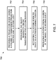
- FIG. 7 there is shown a flow chart to better help illustrate a method for producing a physiological illusion in a viewing guest is provided generally at 700. While the flowchart shows an exemplary step-by-step method, it is to be appreciated that a skilled artisan may rearrange or reorder the steps while maintaining like results.
- Providing a projection device comprising a housing having a transparent projection surface and a strobe light supported by the housing step 702 comprises providing a projection device such as one described with reference to Figures 1-5 .
- the transparent surface may comprise two clear plies and an imaging plate as shown in Figure 3a , or, in the example described above, an LCD monitor as discussed with regard to Figure 4 .
- Producing a projection the object silhouette on the translucent projection surface step 704 may comprise sliding an imaging plate into a gap between the two plies of the transparent projection surface, or in the example described above, the images may be generated by the LCD monitor through signals from the controller. If imaging plates are to be used, an operator may be utilized to change the plates when different images are desired. The plates may also be changed automatically by a instrument functioning as a slide real. Furthermore, an opaque object may be used as the image.
- Activating the strobe when the guest is at a predetermined position step 706 may comprise signaling the controller to activate the strobe.
- the central processor 204 may communicate ride vehicle position through a plurality of track or vehicle sensors which may also be in communication with the central processor 204.
- the central processor may then, at a predetermined time, send a command signal to the controller 202 which may activate the strobe light 106.
- the central processor 204 may send command signals to the controller 202 to control the duration of the strobe light 106.
- duration of the strobe light 106 may correspond to ride vehicle speed.
- the speed of the vehicle may be relatively fast. Therefore, to produce the desired effect of a physiological illusion, the strobe duration may be relatively high when compared to an attraction in which the guest is moving into the projectors field of view at slower speeds. Producing a physiological illusion of the image to a viewing guest stop 708 may then occur.
Landscapes
- Physics & Mathematics (AREA)
- General Physics & Mathematics (AREA)
- Business, Economics & Management (AREA)
- Accounting & Taxation (AREA)
- Marketing (AREA)
- Engineering & Computer Science (AREA)
- Theoretical Computer Science (AREA)
- Optics & Photonics (AREA)
- Illuminated Signs And Luminous Advertising (AREA)
- Projection Apparatus (AREA)
- Radiation-Therapy Devices (AREA)
- Lighting Device Outwards From Vehicle And Optical Signal (AREA)
- Traffic Control Systems (AREA)
- Air Bags (AREA)
- Vehicle Body Suspensions (AREA)
- Eye Examination Apparatus (AREA)
- Endoscopes (AREA)
Applications Claiming Priority (3)
| Application Number | Priority Date | Filing Date | Title |
|---|---|---|---|
| US28773509P | 2009-12-18 | 2009-12-18 | |
| US12/837,004 US8894498B2 (en) | 2009-12-18 | 2010-07-15 | Imaging device, system and method |
| PCT/US2010/045027 WO2011075189A1 (en) | 2009-12-18 | 2010-08-10 | Imaging device, system and method |
Publications (2)
| Publication Number | Publication Date |
|---|---|
| EP2513704A1 EP2513704A1 (en) | 2012-10-24 |
| EP2513704B1 true EP2513704B1 (en) | 2022-10-05 |
Family
ID=44151865
Family Applications (1)
| Application Number | Title | Priority Date | Filing Date |
|---|---|---|---|
| EP10752464.7A Active EP2513704B1 (en) | 2009-12-18 | 2010-08-10 | Imaging device and method |
Country Status (11)
| Country | Link |
|---|---|
| US (1) | US8894498B2 (enExample) |
| EP (1) | EP2513704B1 (enExample) |
| JP (1) | JP5907890B2 (enExample) |
| KR (1) | KR101785128B1 (enExample) |
| CN (1) | CN102804028B (enExample) |
| CA (1) | CA2784663C (enExample) |
| ES (1) | ES2930502T3 (enExample) |
| MY (1) | MY165812A (enExample) |
| RU (1) | RU2539118C2 (enExample) |
| SG (1) | SG181726A1 (enExample) |
| WO (1) | WO2011075189A1 (enExample) |
Families Citing this family (4)
| Publication number | Priority date | Publication date | Assignee | Title |
|---|---|---|---|---|
| KR102051656B1 (ko) * | 2013-01-22 | 2019-12-03 | 삼성전자주식회사 | 투명 디스플레이 장치 및 그 디스플레이 방법 |
| US10350504B2 (en) * | 2016-09-13 | 2019-07-16 | Universal City Studios Llc | Systems and methods for incorporating pneumatic robotic systems into amusement park attractions |
| CN113495406A (zh) | 2020-04-01 | 2021-10-12 | 中强光电股份有限公司 | 交互式投影系统以及投影系统的交互式显示方法 |
| US11590432B2 (en) | 2020-09-30 | 2023-02-28 | Universal City Studios Llc | Interactive display with special effects assembly |
Citations (7)
| Publication number | Priority date | Publication date | Assignee | Title |
|---|---|---|---|---|
| JPH0540448A (ja) * | 1990-03-16 | 1993-02-19 | Sadahide Okumura | 連続動作映像装置および連続動作映像用スクリーンボツクス |
| WO1994006249A1 (en) * | 1992-09-09 | 1994-03-17 | Eichenlaub Jesse B | Stroboscopic illumination system for video displays |
| JPH10171017A (ja) * | 1996-12-16 | 1998-06-26 | Canon Inc | ディスプレー装置 |
| GB2340621A (en) * | 1998-08-18 | 2000-02-23 | Luke Alexander Jerram | Retinal after-image projector and amplifier |
| WO2000023744A2 (en) * | 1998-10-19 | 2000-04-27 | Hanlon David J O | Lighted frame for plastic and traditional canvas painting |
| JP2000172221A (ja) * | 1998-12-07 | 2000-06-23 | Masaomi Yamamoto | 映像表示装置 |
| US20080129963A1 (en) * | 2006-10-27 | 2008-06-05 | Hohl G Burnell | Animation by selected strobing of rotating images |
Family Cites Families (25)
| Publication number | Priority date | Publication date | Assignee | Title |
|---|---|---|---|---|
| US2663960A (en) * | 1949-06-24 | 1953-12-29 | Vincent J Scordley | Illuminated illusion device |
| US3462213A (en) * | 1968-08-26 | 1969-08-19 | Roger Lannes De Montebello | Three-dimensional optical display apparatus |
| US4085932A (en) * | 1976-10-14 | 1978-04-25 | Tomy Kogyo Co., Inc. | Amusement device featuring variable lighting effects |
| US4435053A (en) * | 1982-06-16 | 1984-03-06 | The Zyntrax Corporation | Three-dimensional plural display apparatus |
| US5410345A (en) * | 1992-09-09 | 1995-04-25 | Dimension Technologies, Inc. | Stroboscopic illumination system for video displays |
| AU5899094A (en) * | 1992-12-10 | 1994-07-04 | John M. Dasso | Method and apparatus for generating a three-dimensional effect for two-dimensional images |
| US5346433A (en) * | 1993-02-05 | 1994-09-13 | Inventures, Inc. | Mirror illusion |
| US5407391A (en) * | 1993-05-14 | 1995-04-18 | The Walt Disney Company | Negative bust illusion and related method |
| US5871404A (en) * | 1996-02-09 | 1999-02-16 | Weinreich; Steve | Optical blob |
| US5782698A (en) * | 1996-04-05 | 1998-07-21 | Keller; Allan | Optical illusion device |
| JPH10293550A (ja) | 1997-02-20 | 1998-11-04 | Masaomi Yamamoto | 映像用スクリーンボックスおよび連続動作映像装置 |
| JP4085344B2 (ja) * | 1998-01-16 | 2008-05-14 | ソニー株式会社 | 移動体用画像表示装置および方法 |
| JP2000172220A (ja) | 1998-12-07 | 2000-06-23 | Masaomi Yamamoto | 映像表示装置および映像表示方法 |
| JP2000221921A (ja) * | 1999-02-01 | 2000-08-11 | Masaomi Yamamoto | 移動体用連続映像表示方法および移動体用連続映像表示装置 |
| JP2000221920A (ja) * | 1999-02-01 | 2000-08-11 | Masaomi Yamamoto | 連続動作映像表示装置 |
| JP2000235360A (ja) * | 1999-02-15 | 2000-08-29 | Masaomi Yamamoto | 映像配信方法および映像配信装置 |
| US6190019B1 (en) * | 1999-03-08 | 2001-02-20 | Dimplex North America Limited | Display device with visual effect apparatus |
| RU14355U1 (ru) | 1999-06-10 | 2000-07-20 | Абдурахимов Тимур Рулланович | Аттракцион |
| US6168531B1 (en) * | 1999-06-15 | 2001-01-02 | Sony Corporation | Soup bowl attraction |
| US6929552B1 (en) * | 1999-08-17 | 2005-08-16 | Patrick Allen Hargabus | Quick exchange infinity mirror display apparatus and method |
| CN1400574A (zh) | 2001-08-01 | 2003-03-05 | 王琼韬 | 一种相对运动式广告技术方案 |
| JP4139753B2 (ja) * | 2003-09-05 | 2008-08-27 | 株式会社テンヨー | カード類トリック手品具 |
| US20060135271A1 (en) | 2004-12-17 | 2006-06-22 | Casey Joseph F | Amusement ride vehicle with sensory stimulation effects |
| JP5040448B2 (ja) | 2007-05-30 | 2012-10-03 | 横浜ゴム株式会社 | 空気入りタイヤ |
| US20100058628A1 (en) * | 2008-09-05 | 2010-03-11 | Brian P. Reid | Frame Assembly for Displaying Indicia and Reflecting An Image |
-
2010
- 2010-07-15 US US12/837,004 patent/US8894498B2/en active Active
- 2010-08-10 EP EP10752464.7A patent/EP2513704B1/en active Active
- 2010-08-10 RU RU2012130395/28A patent/RU2539118C2/ru active
- 2010-08-10 WO PCT/US2010/045027 patent/WO2011075189A1/en not_active Ceased
- 2010-08-10 KR KR1020127018692A patent/KR101785128B1/ko active Active
- 2010-08-10 CN CN201080064242.7A patent/CN102804028B/zh active Active
- 2010-08-10 ES ES10752464T patent/ES2930502T3/es active Active
- 2010-08-10 JP JP2012544489A patent/JP5907890B2/ja active Active
- 2010-08-10 CA CA2784663A patent/CA2784663C/en active Active
- 2010-08-10 MY MYPI2012002770A patent/MY165812A/en unknown
- 2010-08-10 SG SG2012044160A patent/SG181726A1/en unknown
Patent Citations (7)
| Publication number | Priority date | Publication date | Assignee | Title |
|---|---|---|---|---|
| JPH0540448A (ja) * | 1990-03-16 | 1993-02-19 | Sadahide Okumura | 連続動作映像装置および連続動作映像用スクリーンボツクス |
| WO1994006249A1 (en) * | 1992-09-09 | 1994-03-17 | Eichenlaub Jesse B | Stroboscopic illumination system for video displays |
| JPH10171017A (ja) * | 1996-12-16 | 1998-06-26 | Canon Inc | ディスプレー装置 |
| GB2340621A (en) * | 1998-08-18 | 2000-02-23 | Luke Alexander Jerram | Retinal after-image projector and amplifier |
| WO2000023744A2 (en) * | 1998-10-19 | 2000-04-27 | Hanlon David J O | Lighted frame for plastic and traditional canvas painting |
| JP2000172221A (ja) * | 1998-12-07 | 2000-06-23 | Masaomi Yamamoto | 映像表示装置 |
| US20080129963A1 (en) * | 2006-10-27 | 2008-06-05 | Hohl G Burnell | Animation by selected strobing of rotating images |
Also Published As
| Publication number | Publication date |
|---|---|
| ES2930502T3 (es) | 2022-12-14 |
| JP5907890B2 (ja) | 2016-04-26 |
| CA2784663A1 (en) | 2011-06-23 |
| KR101785128B1 (ko) | 2017-10-12 |
| MY165812A (en) | 2018-04-27 |
| JP2013514546A (ja) | 2013-04-25 |
| SG181726A1 (en) | 2012-07-30 |
| CN102804028A (zh) | 2012-11-28 |
| US8894498B2 (en) | 2014-11-25 |
| RU2539118C2 (ru) | 2015-01-10 |
| CN102804028B (zh) | 2015-06-17 |
| KR20120112587A (ko) | 2012-10-11 |
| WO2011075189A1 (en) | 2011-06-23 |
| CA2784663C (en) | 2018-02-13 |
| EP2513704A1 (en) | 2012-10-24 |
| US20110151983A1 (en) | 2011-06-23 |
| RU2012130395A (ru) | 2014-01-27 |
Similar Documents
| Publication | Publication Date | Title |
|---|---|---|
| ES2983037T3 (es) | Sistema y método de realidad aumentada de efecto correlativo | |
| CA2767835C (en) | Method and system for filming | |
| ES2895097T3 (es) | Sistema de iluminación arquitectónica de vistas múltiples | |
| US20130201285A1 (en) | 3-d glasses with illuminated light guide | |
| CN113993601B (zh) | 用于虚拟特征开发的系统和方法 | |
| CN114675744B (zh) | Ar眼镜视觉亮度补偿方法、电子设备及ar眼镜 | |
| EP2513704B1 (en) | Imaging device and method | |
| CN103760677B (zh) | 均匀无暗区的背光指向式裸眼3d显示方法、装置、单元与系统 | |
| US20210271124A1 (en) | Advanced liquid crystal film for anti motion sickness and methods thereof | |
| EP2276968A1 (en) | Device and process for controlled conveying of different visual impressions of a room while retaining identical room illumination | |
| US9155971B1 (en) | Selective illumination of physical scenery in amusement park rides | |
| JP4457128B2 (ja) | 遊技機 | |
| JP2008213286A (ja) | 静止画の仮想移動方法及びその装置 | |
| CA3164665C (en) | Correlative effect augmented reality system and method | |
| US20250045998A1 (en) | System for illuminating the face | |
| US20120092848A1 (en) | Photographic Light | |
| GB2543368A (en) | Display apparatus | |
| JP2023114246A (ja) | 光投影装置、光投影システムおよび照明システム | |
| Yamauchi et al. | Demonstration of the light source color on a photograph | |
| CN1876212A (zh) | 用于模拟太空环境的装置 |
Legal Events
| Date | Code | Title | Description |
|---|---|---|---|
| PUAI | Public reference made under article 153(3) epc to a published international application that has entered the european phase |
Free format text: ORIGINAL CODE: 0009012 |
|
| 17P | Request for examination filed |
Effective date: 20120709 |
|
| AK | Designated contracting states |
Kind code of ref document: A1 Designated state(s): AL AT BE BG CH CY CZ DE DK EE ES FI FR GB GR HR HU IE IS IT LI LT LU LV MC MK MT NL NO PL PT RO SE SI SK SM TR |
|
| DAX | Request for extension of the european patent (deleted) | ||
| RAP3 | Party data changed (applicant data changed or rights of an application transferred) |
Owner name: UNIVERSAL CITY STUDIOS LLC |
|
| STAA | Information on the status of an ep patent application or granted ep patent |
Free format text: STATUS: EXAMINATION IS IN PROGRESS |
|
| 17Q | First examination report despatched |
Effective date: 20170317 |
|
| REG | Reference to a national code |
Ref country code: DE Ref legal event code: R079 Ref document number: 602010068506 Country of ref document: DE Free format text: PREVIOUS MAIN CLASS: G02B0027220000 Ipc: G09F0019220000 |
|
| GRAP | Despatch of communication of intention to grant a patent |
Free format text: ORIGINAL CODE: EPIDOSNIGR1 |
|
| STAA | Information on the status of an ep patent application or granted ep patent |
Free format text: STATUS: GRANT OF PATENT IS INTENDED |
|
| RIC1 | Information provided on ipc code assigned before grant |
Ipc: G09F 19/22 20060101AFI20220406BHEP |
|
| INTG | Intention to grant announced |
Effective date: 20220426 |
|
| GRAS | Grant fee paid |
Free format text: ORIGINAL CODE: EPIDOSNIGR3 |
|
| GRAA | (expected) grant |
Free format text: ORIGINAL CODE: 0009210 |
|
| STAA | Information on the status of an ep patent application or granted ep patent |
Free format text: STATUS: THE PATENT HAS BEEN GRANTED |
|
| AK | Designated contracting states |
Kind code of ref document: B1 Designated state(s): AL AT BE BG CH CY CZ DE DK EE ES FI FR GB GR HR HU IE IS IT LI LT LU LV MC MK MT NL NO PL PT RO SE SI SK SM TR |
|
| REG | Reference to a national code |
Ref country code: GB Ref legal event code: FG4D |
|
| REG | Reference to a national code |
Ref country code: CH Ref legal event code: EP |
|
| REG | Reference to a national code |
Ref country code: AT Ref legal event code: REF Ref document number: 1523229 Country of ref document: AT Kind code of ref document: T Effective date: 20221015 |
|
| REG | Reference to a national code |
Ref country code: IE Ref legal event code: FG4D |
|
| REG | Reference to a national code |
Ref country code: DE Ref legal event code: R096 Ref document number: 602010068506 Country of ref document: DE |
|
| REG | Reference to a national code |
Ref country code: ES Ref legal event code: FG2A Ref document number: 2930502 Country of ref document: ES Kind code of ref document: T3 Effective date: 20221214 |
|
| REG | Reference to a national code |
Ref country code: LT Ref legal event code: MG9D |
|
| PG25 | Lapsed in a contracting state [announced via postgrant information from national office to epo] |
Ref country code: NL Free format text: LAPSE BECAUSE OF FAILURE TO SUBMIT A TRANSLATION OF THE DESCRIPTION OR TO PAY THE FEE WITHIN THE PRESCRIBED TIME-LIMIT Effective date: 20221005 |
|
| PG25 | Lapsed in a contracting state [announced via postgrant information from national office to epo] |
Ref country code: SE Free format text: LAPSE BECAUSE OF FAILURE TO SUBMIT A TRANSLATION OF THE DESCRIPTION OR TO PAY THE FEE WITHIN THE PRESCRIBED TIME-LIMIT Effective date: 20221005 Ref country code: PT Free format text: LAPSE BECAUSE OF FAILURE TO SUBMIT A TRANSLATION OF THE DESCRIPTION OR TO PAY THE FEE WITHIN THE PRESCRIBED TIME-LIMIT Effective date: 20230206 Ref country code: NO Free format text: LAPSE BECAUSE OF FAILURE TO SUBMIT A TRANSLATION OF THE DESCRIPTION OR TO PAY THE FEE WITHIN THE PRESCRIBED TIME-LIMIT Effective date: 20230105 Ref country code: LT Free format text: LAPSE BECAUSE OF FAILURE TO SUBMIT A TRANSLATION OF THE DESCRIPTION OR TO PAY THE FEE WITHIN THE PRESCRIBED TIME-LIMIT Effective date: 20221005 Ref country code: FI Free format text: LAPSE BECAUSE OF FAILURE TO SUBMIT A TRANSLATION OF THE DESCRIPTION OR TO PAY THE FEE WITHIN THE PRESCRIBED TIME-LIMIT Effective date: 20221005 |
|
| PG25 | Lapsed in a contracting state [announced via postgrant information from national office to epo] |
Ref country code: PL Free format text: LAPSE BECAUSE OF FAILURE TO SUBMIT A TRANSLATION OF THE DESCRIPTION OR TO PAY THE FEE WITHIN THE PRESCRIBED TIME-LIMIT Effective date: 20221005 Ref country code: LV Free format text: LAPSE BECAUSE OF FAILURE TO SUBMIT A TRANSLATION OF THE DESCRIPTION OR TO PAY THE FEE WITHIN THE PRESCRIBED TIME-LIMIT Effective date: 20221005 Ref country code: IS Free format text: LAPSE BECAUSE OF FAILURE TO SUBMIT A TRANSLATION OF THE DESCRIPTION OR TO PAY THE FEE WITHIN THE PRESCRIBED TIME-LIMIT Effective date: 20230205 Ref country code: HR Free format text: LAPSE BECAUSE OF FAILURE TO SUBMIT A TRANSLATION OF THE DESCRIPTION OR TO PAY THE FEE WITHIN THE PRESCRIBED TIME-LIMIT Effective date: 20221005 Ref country code: GR Free format text: LAPSE BECAUSE OF FAILURE TO SUBMIT A TRANSLATION OF THE DESCRIPTION OR TO PAY THE FEE WITHIN THE PRESCRIBED TIME-LIMIT Effective date: 20230106 |
|
| P01 | Opt-out of the competence of the unified patent court (upc) registered |
Effective date: 20230522 |
|
| REG | Reference to a national code |
Ref country code: DE Ref legal event code: R097 Ref document number: 602010068506 Country of ref document: DE |
|
| PG25 | Lapsed in a contracting state [announced via postgrant information from national office to epo] |
Ref country code: SM Free format text: LAPSE BECAUSE OF FAILURE TO SUBMIT A TRANSLATION OF THE DESCRIPTION OR TO PAY THE FEE WITHIN THE PRESCRIBED TIME-LIMIT Effective date: 20221005 Ref country code: RO Free format text: LAPSE BECAUSE OF FAILURE TO SUBMIT A TRANSLATION OF THE DESCRIPTION OR TO PAY THE FEE WITHIN THE PRESCRIBED TIME-LIMIT Effective date: 20221005 Ref country code: EE Free format text: LAPSE BECAUSE OF FAILURE TO SUBMIT A TRANSLATION OF THE DESCRIPTION OR TO PAY THE FEE WITHIN THE PRESCRIBED TIME-LIMIT Effective date: 20221005 Ref country code: DK Free format text: LAPSE BECAUSE OF FAILURE TO SUBMIT A TRANSLATION OF THE DESCRIPTION OR TO PAY THE FEE WITHIN THE PRESCRIBED TIME-LIMIT Effective date: 20221005 Ref country code: CZ Free format text: LAPSE BECAUSE OF FAILURE TO SUBMIT A TRANSLATION OF THE DESCRIPTION OR TO PAY THE FEE WITHIN THE PRESCRIBED TIME-LIMIT Effective date: 20221005 |
|
| PLBE | No opposition filed within time limit |
Free format text: ORIGINAL CODE: 0009261 |
|
| STAA | Information on the status of an ep patent application or granted ep patent |
Free format text: STATUS: NO OPPOSITION FILED WITHIN TIME LIMIT |
|
| PG25 | Lapsed in a contracting state [announced via postgrant information from national office to epo] |
Ref country code: SK Free format text: LAPSE BECAUSE OF FAILURE TO SUBMIT A TRANSLATION OF THE DESCRIPTION OR TO PAY THE FEE WITHIN THE PRESCRIBED TIME-LIMIT Effective date: 20221005 Ref country code: AL Free format text: LAPSE BECAUSE OF FAILURE TO SUBMIT A TRANSLATION OF THE DESCRIPTION OR TO PAY THE FEE WITHIN THE PRESCRIBED TIME-LIMIT Effective date: 20221005 |
|
| 26N | No opposition filed |
Effective date: 20230706 |
|
| PG25 | Lapsed in a contracting state [announced via postgrant information from national office to epo] |
Ref country code: SI Free format text: LAPSE BECAUSE OF FAILURE TO SUBMIT A TRANSLATION OF THE DESCRIPTION OR TO PAY THE FEE WITHIN THE PRESCRIBED TIME-LIMIT Effective date: 20221005 |
|
| REG | Reference to a national code |
Ref country code: AT Ref legal event code: UEP Ref document number: 1523229 Country of ref document: AT Kind code of ref document: T Effective date: 20221005 |
|
| PG25 | Lapsed in a contracting state [announced via postgrant information from national office to epo] |
Ref country code: MC Free format text: LAPSE BECAUSE OF FAILURE TO SUBMIT A TRANSLATION OF THE DESCRIPTION OR TO PAY THE FEE WITHIN THE PRESCRIBED TIME-LIMIT Effective date: 20221005 |
|
| PG25 | Lapsed in a contracting state [announced via postgrant information from national office to epo] |
Ref country code: MC Free format text: LAPSE BECAUSE OF FAILURE TO SUBMIT A TRANSLATION OF THE DESCRIPTION OR TO PAY THE FEE WITHIN THE PRESCRIBED TIME-LIMIT Effective date: 20221005 |
|
| PG25 | Lapsed in a contracting state [announced via postgrant information from national office to epo] |
Ref country code: LU Free format text: LAPSE BECAUSE OF NON-PAYMENT OF DUE FEES Effective date: 20230810 |
|
| PG25 | Lapsed in a contracting state [announced via postgrant information from national office to epo] |
Ref country code: LU Free format text: LAPSE BECAUSE OF NON-PAYMENT OF DUE FEES Effective date: 20230810 |
|
| REG | Reference to a national code |
Ref country code: BE Ref legal event code: MM Effective date: 20230831 |
|
| REG | Reference to a national code |
Ref country code: IE Ref legal event code: MM4A |
|
| PG25 | Lapsed in a contracting state [announced via postgrant information from national office to epo] |
Ref country code: IE Free format text: LAPSE BECAUSE OF NON-PAYMENT OF DUE FEES Effective date: 20230810 |
|
| PG25 | Lapsed in a contracting state [announced via postgrant information from national office to epo] |
Ref country code: IE Free format text: LAPSE BECAUSE OF NON-PAYMENT OF DUE FEES Effective date: 20230810 |
|
| PG25 | Lapsed in a contracting state [announced via postgrant information from national office to epo] |
Ref country code: BE Free format text: LAPSE BECAUSE OF NON-PAYMENT OF DUE FEES Effective date: 20230831 |
|
| PG25 | Lapsed in a contracting state [announced via postgrant information from national office to epo] |
Ref country code: BG Free format text: LAPSE BECAUSE OF FAILURE TO SUBMIT A TRANSLATION OF THE DESCRIPTION OR TO PAY THE FEE WITHIN THE PRESCRIBED TIME-LIMIT Effective date: 20221005 |
|
| PG25 | Lapsed in a contracting state [announced via postgrant information from national office to epo] |
Ref country code: BG Free format text: LAPSE BECAUSE OF FAILURE TO SUBMIT A TRANSLATION OF THE DESCRIPTION OR TO PAY THE FEE WITHIN THE PRESCRIBED TIME-LIMIT Effective date: 20221005 |
|
| PG25 | Lapsed in a contracting state [announced via postgrant information from national office to epo] |
Ref country code: CY Free format text: LAPSE BECAUSE OF FAILURE TO SUBMIT A TRANSLATION OF THE DESCRIPTION OR TO PAY THE FEE WITHIN THE PRESCRIBED TIME-LIMIT; INVALID AB INITIO Effective date: 20100810 |
|
| PG25 | Lapsed in a contracting state [announced via postgrant information from national office to epo] |
Ref country code: HU Free format text: LAPSE BECAUSE OF FAILURE TO SUBMIT A TRANSLATION OF THE DESCRIPTION OR TO PAY THE FEE WITHIN THE PRESCRIBED TIME-LIMIT; INVALID AB INITIO Effective date: 20100810 |
|
| PGFP | Annual fee paid to national office [announced via postgrant information from national office to epo] |
Ref country code: ES Payment date: 20250901 Year of fee payment: 16 |
|
| PGFP | Annual fee paid to national office [announced via postgrant information from national office to epo] |
Ref country code: DE Payment date: 20250827 Year of fee payment: 16 |
|
| PGFP | Annual fee paid to national office [announced via postgrant information from national office to epo] |
Ref country code: IT Payment date: 20250820 Year of fee payment: 16 |
|
| PGFP | Annual fee paid to national office [announced via postgrant information from national office to epo] |
Ref country code: GB Payment date: 20250827 Year of fee payment: 16 |
|
| PGFP | Annual fee paid to national office [announced via postgrant information from national office to epo] |
Ref country code: FR Payment date: 20250825 Year of fee payment: 16 Ref country code: AT Payment date: 20250827 Year of fee payment: 16 |
|
| PGFP | Annual fee paid to national office [announced via postgrant information from national office to epo] |
Ref country code: CH Payment date: 20250901 Year of fee payment: 16 |
|
| PG25 | Lapsed in a contracting state [announced via postgrant information from national office to epo] |
Ref country code: TR Free format text: LAPSE BECAUSE OF FAILURE TO SUBMIT A TRANSLATION OF THE DESCRIPTION OR TO PAY THE FEE WITHIN THE PRESCRIBED TIME-LIMIT Effective date: 20221005 |