EP2513451B1 - Toroidal continuously variabale transmission - Google Patents
Toroidal continuously variabale transmission Download PDFInfo
- Publication number
- EP2513451B1 EP2513451B1 EP10787535.3A EP10787535A EP2513451B1 EP 2513451 B1 EP2513451 B1 EP 2513451B1 EP 10787535 A EP10787535 A EP 10787535A EP 2513451 B1 EP2513451 B1 EP 2513451B1
- Authority
- EP
- European Patent Office
- Prior art keywords
- variator
- input
- disc
- rollers
- roller
- Prior art date
- Legal status (The legal status is an assumption and is not a legal conclusion. Google has not performed a legal analysis and makes no representation as to the accuracy of the status listed.)
- Not-in-force
Links
Images


Classifications
-
- F—MECHANICAL ENGINEERING; LIGHTING; HEATING; WEAPONS; BLASTING
- F16—ENGINEERING ELEMENTS AND UNITS; GENERAL MEASURES FOR PRODUCING AND MAINTAINING EFFECTIVE FUNCTIONING OF MACHINES OR INSTALLATIONS; THERMAL INSULATION IN GENERAL
- F16H—GEARING
- F16H63/00—Control outputs from the control unit to change-speed- or reversing-gearings for conveying rotary motion or to other devices than the final output mechanism
- F16H63/02—Final output mechanisms therefor; Actuating means for the final output mechanisms
- F16H63/04—Final output mechanisms therefor; Actuating means for the final output mechanisms a single final output mechanism being moved by a single final actuating mechanism
- F16H63/06—Final output mechanisms therefor; Actuating means for the final output mechanisms a single final output mechanism being moved by a single final actuating mechanism the final output mechanism having an indefinite number of positions
- F16H63/067—Final output mechanisms therefor; Actuating means for the final output mechanisms a single final output mechanism being moved by a single final actuating mechanism the final output mechanism having an indefinite number of positions mechanical actuating means
-
- F—MECHANICAL ENGINEERING; LIGHTING; HEATING; WEAPONS; BLASTING
- F16—ENGINEERING ELEMENTS AND UNITS; GENERAL MEASURES FOR PRODUCING AND MAINTAINING EFFECTIVE FUNCTIONING OF MACHINES OR INSTALLATIONS; THERMAL INSULATION IN GENERAL
- F16H—GEARING
- F16H15/00—Gearings for conveying rotary motion with variable gear ratio, or for reversing rotary motion, by friction between rotary members
- F16H15/02—Gearings for conveying rotary motion with variable gear ratio, or for reversing rotary motion, by friction between rotary members without members having orbital motion
- F16H15/04—Gearings providing a continuous range of gear ratios
- F16H15/06—Gearings providing a continuous range of gear ratios in which a member A of uniform effective diameter mounted on a shaft may co-operate with different parts of a member B
- F16H15/32—Gearings providing a continuous range of gear ratios in which a member A of uniform effective diameter mounted on a shaft may co-operate with different parts of a member B in which the member B has a curved friction surface formed as a surface of a body of revolution generated by a curve which is neither a circular arc centered on its axis of revolution nor a straight line
- F16H15/36—Gearings providing a continuous range of gear ratios in which a member A of uniform effective diameter mounted on a shaft may co-operate with different parts of a member B in which the member B has a curved friction surface formed as a surface of a body of revolution generated by a curve which is neither a circular arc centered on its axis of revolution nor a straight line with concave friction surface, e.g. a hollow toroid surface
- F16H15/38—Gearings providing a continuous range of gear ratios in which a member A of uniform effective diameter mounted on a shaft may co-operate with different parts of a member B in which the member B has a curved friction surface formed as a surface of a body of revolution generated by a curve which is neither a circular arc centered on its axis of revolution nor a straight line with concave friction surface, e.g. a hollow toroid surface with two members B having hollow toroid surfaces opposite to each other, the member or members A being adjustably mounted between the surfaces
-
- F—MECHANICAL ENGINEERING; LIGHTING; HEATING; WEAPONS; BLASTING
- F16—ENGINEERING ELEMENTS AND UNITS; GENERAL MEASURES FOR PRODUCING AND MAINTAINING EFFECTIVE FUNCTIONING OF MACHINES OR INSTALLATIONS; THERMAL INSULATION IN GENERAL
- F16H—GEARING
- F16H61/00—Control functions within control units of change-speed- or reversing-gearings for conveying rotary motion ; Control of exclusively fluid gearing, friction gearing, gearings with endless flexible members or other particular types of gearing
- F16H61/66—Control functions within control units of change-speed- or reversing-gearings for conveying rotary motion ; Control of exclusively fluid gearing, friction gearing, gearings with endless flexible members or other particular types of gearing specially adapted for continuously variable gearings
- F16H61/664—Friction gearings
- F16H61/6648—Friction gearings controlling of shifting being influenced by a signal derived from the engine and the main coupling
-
- F—MECHANICAL ENGINEERING; LIGHTING; HEATING; WEAPONS; BLASTING
- F16—ENGINEERING ELEMENTS AND UNITS; GENERAL MEASURES FOR PRODUCING AND MAINTAINING EFFECTIVE FUNCTIONING OF MACHINES OR INSTALLATIONS; THERMAL INSULATION IN GENERAL
- F16H—GEARING
- F16H61/00—Control functions within control units of change-speed- or reversing-gearings for conveying rotary motion ; Control of exclusively fluid gearing, friction gearing, gearings with endless flexible members or other particular types of gearing
- F16H61/66—Control functions within control units of change-speed- or reversing-gearings for conveying rotary motion ; Control of exclusively fluid gearing, friction gearing, gearings with endless flexible members or other particular types of gearing specially adapted for continuously variable gearings
- F16H61/664—Friction gearings
- F16H61/6649—Friction gearings characterised by the means for controlling the torque transmitting capability of the gearing
Definitions
- the present invention relates to infinitely variable ratio transmission apparatus of the toroidal race rolling traction type, hereinafter referred to as a variator.
- the basic form of variator comprises a toroidally-recessed input disc rotated by an input drive shaft and a toroidally-recessed output disc arranged coaxially with respect to the input disc.
- a plurality of rollers is provided in the toroidal cavity defined between the input and output discs and power is transmitted between the input disc and the output disc by means of the rollers.
- An elasto-hydrodynamic oil film is present between the rollers and the input and output discs.
- the properties of the elasto-hydrodynamic fluid are such that when the fluid is compressed it becomes highly viscous, such that as pressure is exerted at the contact point between the rollers and the discs, the oil transmits power from one to the other.
- Rollers are mounted on roller carriages which pivot such that the points of contact of the rollers on the input and output discs can be adjusted in order to alter the effective ratio of the variator.
- a so-called torque controlled variator transverse forces are applied to the roller carriages which are typically applied by means of double-acting hydraulic pistons in relatively high power, high torque applications or by means of a lever on which a pair of roller carriages is mounted, each of which carries a single roller.
- the effective ratio of the variator is dependent upon the input and output torques on the variator, and the transverse forces applied to the rollers.
- a so-called ratio-controlled variator the inclination of the rollers is specified, so that the effective ratio of the variator is defined without reference to the values of the torques on the variator.
- the invention comprises a variator as claimed in the appended claim 1.
- Optional features are set out in the dependent claims.
- the minimum ratio of the variator is -1.
- the minimum ratio may have a different value, e.g. - 0.4.
- the non-identical nature of the opposed profiled inner faces of the input and output discs of some examples allows the ratio range of the transmission to be tailored to suit a particular application, for example if the transmission is only required to output a positive ratio.
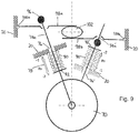
- Figs. 1 to 3 illustrate a supercharger S for an internal combustion engine, connected to, and driven by, a first embodiment of continuously variable transmission system in the form of a variator V via an epicyclic gear set E.
- the supercharger is entirely conventional and need not be described in detail.
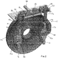
- the variator V comprises a toroidally-recessed input disc 10 facing a toroidally-recessed output disc 12.
- Two rollers 14, 16 are rotatably mounted on one end of respective roller carriages 17 (see Fig. 2 ) in the toroidal cavity defined between the opposed toroidally-recessed faces of the input and output discs 10, 12, to transmit drive from the input disc 10 to the output disc 12 with a ratio which is variable by tilting the rollers 14, 16.
- the drive is actually transmitted by a very thin layer of elasto-hydrodynamic fluid between the rollers 14, 16 and the opposed profiled inner faces of the input and output discs 10, 12.
- the significant characteristic of elasto-hydrodynamic fluid is that it becomes highly viscous when pressure is applied to it, allowing torque to be transmitted between the input and output discs and the rollers.
- the input disc 10 is mounted coaxially with, but is not rotated directly by, an input shaft 18 which passes through the input disc 10 and through the housing 20 of the variator.
- the input shaft 18 is hollow and its inner end is secured to one side of a thrust bearing 22.
- the opposite end is mounted by means of two sets of bearings 24, 26 located within the housing, between which an annular seal 28 is mounted.
- the input shaft 18 is rotatable by means of a pulley 30 which is rotated by means of a belt driven by the output of an engine.
- the input shaft 18 passes through a circular aperture 32 in the centre of the input disc 10.
- An end-load arrangement illustrated generally at 34 applies a force in a direction parallel to the rotational axis of the variator (known as the end load) to the input disc 10, in proportion to the input torque.
- the end load compresses the elasto-hydrodynamic fluid at the points of contact between the input and output discs 10, 12 and the rollers 14, 16 and allow torque to be transmitted.
- the end load mechanism 34 also transmits torque from the input shaft 18 to the input disc 10, as will be explained.
- the end load mechanism 34 comprises three spherical balls 36 mounted in profiled part-circular running tracks 38, 39 formed in the outer face of the input disc 10 and in the inner face of a supporting back plate 40.
- the tracks 38, 39 extend from just less than 120 °, are equally angularly spaced and are at a constant diameter.
- the depth of the tracks 38, 39 varies smoothly along the tracks from a minimum depth at one end to a maximum at the opposite end and the tracks in the input disc and the back plate are reversed, so that when the balls 36 are at the minimum depth at one end of the tracks in one of the input disc 10 and back plate 40, they are at the maximum depth at one end of the tracks in the other of the input disc and back plate.
- the supporting back plate 40 is mounted on, and rotates with the input shaft 18 by means of a splined connection 42, which allows the back plate 40 to move along the input shaft 18.
- a conical Belville washer 44 extends between the outer face of the back plate 40 and a retaining circlip 46 on the outer surface of the input shaft 18 in order to provide a preload, thereby producing a minimum end load.
- the input pulley 30 is rotated which applies an input torque to the input shaft 18.
- the back plate 40 of the end load mechanism 34 rotates with the input shaft 18 whereas the input disc 10 does not, although the input disc 10 can move angularly with respect to the input shaft 18, subject to the restrictions of the back plate 40 and the rollers 14, 16. Consequently, as the input shaft 18 rotates, the back plate 40 rotates slightly with respect to the input disc 10, thereby causing the balls 36 to travel along their running tracks 38 to an extent proportional to the applied torque thereby providing an axial end load on the input disc 10 proportional to the input torque and also causing the input disc 10 to rotate. At constant end load, the input disc 10 therefore rotates at the same speed as the input shaft 18, with torque being transmitted from the input shaft 18 to the input disc 10 via the end load mechanism 34.
- the rotation of the input disc 10 is transmitted via the rollers 14, 16 to the output disc 12, the rotation of the output disc 12 being transmitted to the annulus of a conventional traction epicyclic gear set E which is arranged to rotate the drive shaft of the conventional supercharger.
- the effective ratio Rv of the variator is determined by adjusting the angle of inclination of the rollers 14, 16, thereby changing the contact points of the rollers on the inputs discs 10 and output discs 12. This is achieved by adjusting the position of a control rod 58 which may be displaced, for example, by a stepper motor. As a result, the output speed of the variator output disc 12 with respect to the input speed of the variator input shaft 19 can be specified precisely.
- the rotational output of the variator is then transmitted to the epicyclic gear set E, which in turn rotates the input shaft of the supercharger S.
- rollers 14, 16 are mounted on diametrically opposed sides of the rotational axis of the input and output discs 10, 12.
- Each roller carriage 17 is formed from a metal rod of circular cross section having a radially outer straight portion 17a merging with a first outwardly inclined intermediate portion 17b which in turn merges with a second intermediate portion 17c parallel to, but offset with respect to, the first portion.
- the second intermediate portion 17c merges with a roller mounting portion 17d which extends perpendicularly to the second intermediate portion and which receives a bearing 50 by means of which the rollers 14, 6 are mounted.
- the roller carriage 17 is therefore in the form of a rod which assumes the general shape of a question mark.
- each roller carriage 17 passes through the variator housing 20 and is rotatably mounted with respect to the housing by means of a bearing 52.
- the end of each roller carriage projecting through the housing is also secured to a collar 54 which is fixed to a respective sector gear 56 which meshes with a toothed control rod 58 extending, and being displaceable, parallel to the rotational axis of the variator. Displacement of the control rod 58 causes the sector gears 56 to pivot through a corresponding angle which in turn causes the roller carriages 17 to pivot and thereby moves the position of the rollers 14, 16 with respect to the input and output discs 10, 12, thereby altering the effective ratio of the variator.
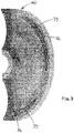
- roller-engaging faces of the input and output discs, 10, 12 are assymetrical and non-identical.
- the rollers 14, 16 in the "zero" position, lying parallel to the rotational axis of the variator, the rollers at the minimum radius of the input disc 10 and the maximum radius of the output disc 12.
- the rollers can be moved to the other extreme position, shown in dotted lines in Fig. 1 , in which the rollers are located near the maximum possible radius of the input disc and the minimal possible radius of the output disc. This ensures that the output ratio of the variator is always greater than or equal to 1.
- the roller-engaging faces of the input and output discs 10, 12 are not identical.
- the variator V will only be required to produce a positive ratio, greater than 1 , and there is therefore no requirement for the variator V to be able to produce a ratio lower than one. Consequently, the input and output disc surfaces 10, 12 are arranged so that when the rollers 14, 16 are in contact with the smallest diameter of the input disc 10 and the largest diameter of the output disc 12, the output ratio Rv of the variator V is 1 and the rollers are then adjustable to increase the variator output ratio Rv to a ratio greater than 1 by engaging the radially outer portions of the input disc 10 and radially inner portions of the output disc 12.
- the variator is "ratio controlled", i.e. the inclination of the rollers 14, 16 is set to the desired angle by appropriate adjustment of the control rod 58.
- the variator is "torque controlled", i.e. rather than setting the inclination of the rollers, a reaction force is applied to the roller carriage, whereby the inclination (ratio) of the rollers is a direct result of the sum of the reaction force and the tangential forces on the roller from the input and output discs 10, 12.
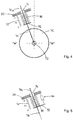
- roller 70 is mounted on a stub axle 72 which in turn is mounted on a roller carriage 74.
- the stub axle 72 and roller carriage can, for example, be in the form of the angled roller carriage 17 of the first embodiment.
- the roller carriage terminates in a straight section 74a which passes through a guide aperture 76 in the housing 20 of the variator, whereby the roller carriage is constrained to be displaceable longitudinally in the direction of the straight section 74a, as indicated by arrows 78.
- a compression spring 80 is disposed around the straight section 74a of the roller carriage 74, between the housing 20 and a stop 82 on the roller carriage.
- FIG. 5 A variation of the embodiment of Fig. 4 is illustrated in Fig. 5 .
- the embodiment of Fig. 5 is identical to that of Fig. 4 , except that the movement of the roller carriage (and therefore of the roller) is damped, by means of a damper 84 mounted between the housing 20 of the variator and the stop 82 on the roller carriage.
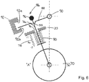
- FIG. 6 A further embodiment is illustrated in Fig. 6 .
- the embodiment includes all of the features of the Fig. 4 embodiment (and, optionally, the Fig. 5 variant) but in addition includes a ratio limiting means 86.
- the ratio limiting means comprises a plate 88 which is pivotally mounted at pivot 90 to the variator housing 20. The rotation of the plate is limited in both directions by means of stop surfaces 92a, 92b of the stop member 92.
- the roller carriage rod 74a passes through a guide aperture 94 in the plate 88 and is prevented from passing completely through the plate by a stop member 96 affixed to one end.
- the roller 70 is constrained by its two point contacts "A" with the input and output discs 10, 12 and the aperture 76 through which the roller carriage rod 74a passes.
- the roller carriage rod 74a has a certain amount of freedom in the aperture 76 since the roller precesses round the toroid as a function of ratio.
- Rotation of the plate 88 about pivot 90 applies a travel limit to the roller.
- the rotation of the plate can be achieved by an external control function or, more simply, by a mechanical linkage (e.g. a cable) to the throttle pedal of the vehicle in which the variator and supercharger are fitted.
- a mechanical linkage e.g. a cable
- the plate 88 is connected to the throttle pedal, as the pedal travel increases the plate rotates downwardly (anticlockwise in Fig. 6 ), allowing the full variator ratio spread.
- the downward plate rotation is small and if the plate 88 engages the stop member 96 on the end of the roller carriage rod 74a, it urges the roller upwards, against the restoring force of the spring 80, towards the minimum ratio position.
- the variator may be at its minimum ratio when the rotational axis of the rollers is perpendicular to the rotational axis of the input and output discs 10, 12.
- Fig. 7 is a variant of Fig. 4 embodiment and shows that the principle is applicable to a plurality of rollers (in this case three, but it could be a higher or lower number such as 2 or 4).
- the variant shows three identical rollers 70, each of which has an identical roller carriage 74 and is provided with an identical compression spring 80. Each roller 70 moves independently of the others and thus any imbalances in the system can be absorbed.
- the embodiment of Fig. 8 is a variant of the Fig. 6 embodiment, in which a ratio limiting means 86' is applied to the roller carriage rods 74a of two rollers 70 (only one of which is visible in the drawing).
- the ratio limiting means 86' comprises a plate 88' having two plate portions 88a, 88b connected together and pivotable about a common pivot 90.
- the plate portion 88a is identical to the plate 88 of the Fig. 6 embodiment.
- the arrangement of the plate portion 88b and the associated carriage rod 74a is "reversed".
- the stop member 96' on the carriage rod 74a associated with the plate portion 88b is located part-way along the carriage rod and is adapted to engage the undersurface of the plate portion 88b.
- the stop 82' on the carriage rod 74 is adjacent to the stop member 96' and is arranged outwardly of the portion of the housing engaged by the spring 80. Consequently, inward movement of the carriage rod 74a compresses the spring 80. This is necessary since the two rollers 70 move in opposite directions to increase or decrease the variator ratio.
- the plate portions 88a, 88b pivot together and the plate portion 88a is engageable with the stop surfaces 92a, 92b of the stop member, as in the Fig. 6 embodiment.
- Fig. 9 shows a variant of the Fig. 8 arrangement, in which separate plates 98a, 98b are provide for the individual roller carriage rods 74a, each plate being separately pivotally mounted at pivot 100a, 100b to the variator housing 20.
- a cam 102 engages the undersurface of plate 98a and the upper surface of the plate 98b.
- the cam produces a ratio limiting function, as in Fig. 8 , but the ratio limiting is adjustable by adjusting the rotational position of the cam 102.
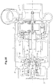
- FIG. 10 A further embodiment is illustrated in Fig. 10 .
- This embodiment is very similar to that of Fig. 1 and the same reference numerals have been used to denote the same features and the same reference numerals with the addition of a prime (') have been used to denote similar features.
- the embodiments of Figs. 4 to 9 which relate to the roller control mechanism, are applicable to the embodiment of Fig. 10 in the same way as for the embodiment of Fig.1 (but with a different ratio spread, as will be explained).
- the main difference between the embodiments of Figs. 1 and 10 is that the ratio spread is increased.
- the roller-engaging faces of the input and output discs 10, 12 are not identical.
- the variator in that embodiment is arranged to have a ratio spread from -1 to -2, such that the ratio was -1 when the rollers 14, 16 are in contact with the smallest diameter of the input disc 10 and the largest diameter of the output disc 12.
- the ratio spread is increased to -0.4 to -2.5. Consequently, the maximum and minimum values of Rv shown in Figs. 4 to 9 are increased and the shape of the opposed faces of the input and output discs 10', 12' are arranged to allow the increased ratio spread (in fact, the opposed faces are identical in the Fig. 10 embodiment).
- the invention is not restricted to the details of the foregoing embodiments.
- end load mechanism other than the end load mechanism described could be used.
- the invention is applicable to a variator having 2, 3 or more rollers in contact with the input and output discs 10, 12 and/or for variators having more than one toroidal cavity.
Landscapes
- Engineering & Computer Science (AREA)
- General Engineering & Computer Science (AREA)
- Mechanical Engineering (AREA)
- Friction Gearing (AREA)
- Supercharger (AREA)
Applications Claiming Priority (2)
| Application Number | Priority Date | Filing Date | Title |
|---|---|---|---|
| GBGB0920546.9A GB0920546D0 (en) | 2009-11-24 | 2009-11-24 | Drive mechanism for infinitely variable transmission |
| PCT/GB2010/051949 WO2011064572A2 (en) | 2009-11-24 | 2010-11-23 | Drive mechanism for infinitely variable transmission |
Publications (2)
| Publication Number | Publication Date |
|---|---|
| EP2513451A2 EP2513451A2 (en) | 2012-10-24 |
| EP2513451B1 true EP2513451B1 (en) | 2017-08-16 |
Family
ID=41565774
Family Applications (1)
| Application Number | Title | Priority Date | Filing Date |
|---|---|---|---|
| EP10787535.3A Not-in-force EP2513451B1 (en) | 2009-11-24 | 2010-11-23 | Toroidal continuously variabale transmission |
Country Status (6)
| Country | Link |
|---|---|
| US (1) | US9341264B2 (enExample) |
| EP (1) | EP2513451B1 (enExample) |
| JP (2) | JP5984673B2 (enExample) |
| CN (1) | CN102803680B (enExample) |
| GB (1) | GB0920546D0 (enExample) |
| WO (1) | WO2011064572A2 (enExample) |
Families Citing this family (37)
| Publication number | Priority date | Publication date | Assignee | Title |
|---|---|---|---|---|
| US7011600B2 (en) | 2003-02-28 | 2006-03-14 | Fallbrook Technologies Inc. | Continuously variable transmission |
| CN102407766B (zh) | 2005-10-28 | 2014-11-19 | 福博科知识产权有限责任公司 | 电动驱动器 |
| DK1954959T3 (da) | 2005-11-22 | 2013-08-26 | Fallbrook Ip Co Llc | Kontinuerlig variabel transmission |
| EP1963713B1 (en) | 2005-12-09 | 2015-02-25 | Fallbrook Intellectual Property Company LLC | Continuously variable transmission |
| EP1811202A1 (en) | 2005-12-30 | 2007-07-25 | Fallbrook Technologies, Inc. | A continuously variable gear transmission |
| US8738255B2 (en) | 2007-02-01 | 2014-05-27 | Fallbrook Intellectual Property Company Llc | Systems and methods for control of transmission and/or prime mover |
| WO2008100792A1 (en) | 2007-02-12 | 2008-08-21 | Fallbrook Technologies Inc. | Continuously variable transmissions and methods therefor |
| TWI461615B (zh) | 2007-02-16 | 2014-11-21 | Fallbrook Ip Co Llc | 無限可變變速器、連續可變變速器、方法、組件、次組件以及其零件 |
| EP2573425A3 (en) | 2007-04-24 | 2017-07-26 | Fallbrook Intellectual Property Company LLC | Electric traction drives |
| RU2480647C2 (ru) | 2007-07-05 | 2013-04-27 | Фоллбрук Текнолоджиз Инк. (Сша/Сша) | Трансмиссия с бесступенчатым изменением скорости |
| US8996263B2 (en) | 2007-11-16 | 2015-03-31 | Fallbrook Intellectual Property Company Llc | Controller for variable transmission |
| JP5783723B2 (ja) | 2007-12-21 | 2015-09-24 | フォールブルック インテレクチュアル プロパティー カンパニー エルエルシー | 自動変速機及びその方法 |
| JP5457438B2 (ja) | 2008-06-06 | 2014-04-02 | フォールブルック インテレクチュアル プロパティー カンパニー エルエルシー | 無限可変変速機、及び無限可変変速機用の制御システム |
| JP5230804B2 (ja) | 2008-06-23 | 2013-07-10 | フォールブルック インテレクチュアル プロパティー カンパニー エルエルシー | 連続可変変速機 |
| US8469856B2 (en) | 2008-08-26 | 2013-06-25 | Fallbrook Intellectual Property Company Llc | Continuously variable transmission |
| US8167759B2 (en) | 2008-10-14 | 2012-05-01 | Fallbrook Technologies Inc. | Continuously variable transmission |
| KR101718754B1 (ko) | 2009-04-16 | 2017-03-22 | 폴브룩 인텔렉츄얼 프로퍼티 컴퍼니 엘엘씨 | 무단 변속기를 위한 고정자 조립체 및 시프팅 장치 |
| US8910614B2 (en) | 2010-02-24 | 2014-12-16 | Eaton Corporation | Supercharger with continuously variable drive system |
| US8512195B2 (en) | 2010-03-03 | 2013-08-20 | Fallbrook Intellectual Property Company Llc | Infinitely variable transmissions, continuously variable transmissions, methods, assemblies, subassemblies, and components therefor |
| US8888643B2 (en) | 2010-11-10 | 2014-11-18 | Fallbrook Intellectual Property Company Llc | Continuously variable transmission |
| WO2013112408A1 (en) | 2012-01-23 | 2013-08-01 | Fallbrook Intellectual Property Company Llc | Infinitely variable transmissions, continuously variable transmissions methods, assemblies, subassemblies, and components therefor |
| US9599218B2 (en) * | 2012-08-16 | 2017-03-21 | Ultimate Transmissions Pty Ltd | Modulated clamping force generator for Toroidal CVT |
| GB2511461B (en) * | 2013-01-10 | 2015-08-05 | Torotrak Dev Ltd | Drive Arrangement for a Supercharger |
| CN105229339B (zh) * | 2013-02-13 | 2019-11-19 | 艾里逊变速箱公司 | 用于诸如增压器的发动机辅助装置的驱动装置 |
| JP6660876B2 (ja) | 2013-04-19 | 2020-03-11 | フォールブルック インテレクチュアル プロパティー カンパニー エルエルシー | 連続可変変速機 |
| CN103470749B (zh) * | 2013-09-06 | 2015-08-26 | 浙江德孚力汽车变速箱有限公司 | 适用于锥环式无级变速器的故障保护装置 |
| GB201321152D0 (en) * | 2013-11-29 | 2014-01-15 | Torotrak Dev Ltd | Compressor arrangement for a supercharger |
| US10400872B2 (en) | 2015-03-31 | 2019-09-03 | Fallbrook Intellectual Property Company Llc | Balanced split sun assemblies with integrated differential mechanisms, and variators and drive trains including balanced split sun assemblies |
| GB2537151B (en) * | 2015-04-09 | 2020-09-23 | Allison Transm Inc | An auxiliary drive arrangement having a prime mover output rotatable relative to a variable speed transmission input |
| US10502289B2 (en) * | 2015-06-27 | 2019-12-10 | Supra Lumina Technologies Inc. | Asymmetric toroidal transmission system |
| US10047861B2 (en) | 2016-01-15 | 2018-08-14 | Fallbrook Intellectual Property Company Llc | Systems and methods for controlling rollback in continuously variable transmissions |
| AU2017234934A1 (en) * | 2016-03-18 | 2018-10-04 | Fallbrook Intellectual Property Company Llc | Continuously variable transmissions systems and methods |
| US10023266B2 (en) | 2016-05-11 | 2018-07-17 | Fallbrook Intellectual Property Company Llc | Systems and methods for automatic configuration and automatic calibration of continuously variable transmissions and bicycles having continuously variable transmissions |
| US10253881B2 (en) | 2016-05-20 | 2019-04-09 | Fallbrook Intellectual Property Company Llc | Systems and methods for axial force generation |
| WO2018174099A1 (ja) * | 2017-03-21 | 2018-09-27 | 日本精工株式会社 | トロイダル無段変速機用押圧装置 |
| US11215268B2 (en) | 2018-11-06 | 2022-01-04 | Fallbrook Intellectual Property Company Llc | Continuously variable transmissions, synchronous shifting, twin countershafts and methods for control of same |
| WO2020176392A1 (en) | 2019-02-26 | 2020-09-03 | Fallbrook Intellectual Property Company Llc | Reversible variable drives and systems and methods for control in forward and reverse directions |
Family Cites Families (27)
| Publication number | Priority date | Publication date | Assignee | Title |
|---|---|---|---|---|
| US2850920A (en) | 1950-12-21 | 1958-09-09 | Rockwell Spring & Axle Co | Vehicle drive mechanism |
| US2850910A (en) * | 1954-03-12 | 1958-09-09 | Excelermatic | Variable speed power transmission mechanisms |
| US4428246A (en) * | 1981-12-31 | 1984-01-31 | Excelermatic Inc. | Infinitely variable traction roller transmission |
| US4744261A (en) * | 1985-11-27 | 1988-05-17 | Honeywell Inc. | Ball coupled compound traction drive |
| JP2568188B2 (ja) * | 1987-02-17 | 1996-12-25 | マツダ株式会社 | エンジンの機械式過給装置 |
| JPH05203007A (ja) * | 1992-01-22 | 1993-08-10 | Toyota Motor Corp | トロイダル式無段変速機 |
| JP3281100B2 (ja) * | 1993-03-29 | 2002-05-13 | 栃木富士産業株式会社 | 過給機 |
| GB9505346D0 (en) * | 1995-03-16 | 1995-05-03 | Fellows Thomas G | Improvements in or relating to continuously-variable-ratio transmissions |
| WO1997018982A1 (en) * | 1995-11-20 | 1997-05-29 | Torotrak (Development) Limited | Improvements in or relating to position servo systems |
| DE19754725A1 (de) * | 1997-12-10 | 1999-06-17 | Zahnradfabrik Friedrichshafen | Stufenloses Reibradgetriebe |
| JP3688178B2 (ja) * | 2000-03-10 | 2005-08-24 | 光洋精工株式会社 | トロイダル型無段変速機 |
| JP3779550B2 (ja) * | 2001-02-06 | 2006-05-31 | 株式会社ジェイテクト | トロイダル型無段変速機 |
| US20030087722A1 (en) * | 2001-11-08 | 2003-05-08 | Peter Visscher | Continuously variable transmission |
| GB0201628D0 (en) * | 2002-01-24 | 2002-03-13 | Torotrak Dev Ltd | Improvements relating to continuously variable transmissions |
| JP4075492B2 (ja) * | 2002-07-11 | 2008-04-16 | 株式会社ジェイテクト | トロイダル型無段変速機のトルク伝達部材の製造方法 |
| GB2394518A (en) * | 2002-10-23 | 2004-04-28 | Torotrak Dev Ltd | Continuously variable ratio transmission unit and method of assembly thereof |
| JP4055615B2 (ja) * | 2003-03-18 | 2008-03-05 | 株式会社ジェイテクト | トロイダル型無段変速機 |
| GB0316382D0 (en) * | 2003-07-12 | 2003-08-13 | Torotrak Dev Ltd | Continuously variable ratio transmission assembly and method of control of same |
| DE10338270B4 (de) * | 2003-08-15 | 2005-10-20 | Getrag Getriebe Zahnrad | Variator und Variatoranordnung |
| GB2423122A (en) * | 2005-02-11 | 2006-08-16 | Torotrak Dev Ltd | A variator roller carriages moved by a lever |
| US8276549B2 (en) * | 2007-08-17 | 2012-10-02 | GM Global Technology Operations LLC | Flexible fuel variable boost supercharged engine |
| GB2455337A (en) * | 2007-12-06 | 2009-06-10 | Infinitrak Llc | Toroidal variator with damped control lever |
| GB2459857A (en) * | 2008-05-07 | 2009-11-11 | Torotrak Dev Ltd | A CVT variator with sintered components |
| GB2474870A (en) * | 2009-10-29 | 2011-05-04 | Torotrak Dev Ltd | Infinitely variable transmission |
| RU2603174C2 (ru) * | 2011-05-06 | 2016-11-20 | Алтимейт Трансмишенс Пти Лтд | Тороидальный тяговый привод с регулируемой скоростью |
| GB201200357D0 (en) * | 2012-01-10 | 2012-02-22 | Torotrak Dev Ltd | Variator |
| JP2013204604A (ja) * | 2012-03-27 | 2013-10-07 | Honda Motor Co Ltd | トロイダル型無段変速機構 |
-
2009
- 2009-11-24 GB GBGB0920546.9A patent/GB0920546D0/en not_active Ceased
-
2010
- 2010-11-23 CN CN201080062209.0A patent/CN102803680B/zh not_active Expired - Fee Related
- 2010-11-23 WO PCT/GB2010/051949 patent/WO2011064572A2/en not_active Ceased
- 2010-11-23 JP JP2012540497A patent/JP5984673B2/ja not_active Expired - Fee Related
- 2010-11-23 EP EP10787535.3A patent/EP2513451B1/en not_active Not-in-force
- 2010-11-23 US US13/511,985 patent/US9341264B2/en active Active
-
2016
- 2016-08-02 JP JP2016151819A patent/JP6422468B2/ja not_active Expired - Fee Related
Non-Patent Citations (1)
| Title |
|---|
| None * |
Also Published As
| Publication number | Publication date |
|---|---|
| CN102803680A (zh) | 2012-11-28 |
| CN102803680B (zh) | 2017-06-06 |
| JP6422468B2 (ja) | 2018-11-14 |
| US9341264B2 (en) | 2016-05-17 |
| WO2011064572A2 (en) | 2011-06-03 |
| EP2513451A2 (en) | 2012-10-24 |
| JP2017009119A (ja) | 2017-01-12 |
| JP2013511687A (ja) | 2013-04-04 |
| US20130017925A1 (en) | 2013-01-17 |
| GB0920546D0 (en) | 2010-01-06 |
| JP5984673B2 (ja) | 2016-09-06 |
| WO2011064572A3 (en) | 2011-07-21 |
Similar Documents
| Publication | Publication Date | Title |
|---|---|---|
| EP2513451B1 (en) | Toroidal continuously variabale transmission | |
| CA2791307C (en) | Infinitely variable transmissions, continuously variable transmissions, methods, assemblies, subassemblies, and components therefor | |
| US4735598A (en) | Continuously variable V-belt transmission | |
| EP3458745A1 (en) | Systems and methods for axial force generation | |
| US20190323582A1 (en) | Idler assembly for a ball variator continuously variable transmission | |
| WO2014026238A1 (en) | Modulated clamping force generator for toroidal cvt | |
| CN103890455B (zh) | 过夹紧保护方法及其夹紧机构 | |
| US11047456B2 (en) | Variators | |
| WO2017151568A1 (en) | Shift actuator system and method for a continuously variable ball planetary transmission having a rotating and/or grounded carrier | |
| US20190154147A1 (en) | Non-synchronous shift control method and assemblies for continuously variable transmissions | |
| US20180135734A1 (en) | Electromagnetic Device For Ball-Type Continuously Variable Transmission | |
| US20180135742A1 (en) | Ball Variator Continuously Variable Transmission | |
| US20180119785A1 (en) | Power Converter Having A Ball-Type Continuously Variable Transmission | |
| WO2018222660A1 (en) | Components and assemblies for a ball-type continuously variable planetary transmission | |
| US20180128357A1 (en) | Articulating Sub-Housing For A Ball-Type Continuously Variable Planetary Transmission | |
| US20190271379A1 (en) | Passive preload control for a ball-type continuously variable planetary transmission | |
| WO2018187424A1 (en) | Passive ratio control methods for a ball-type planetary transmission | |
| HK1180382A (en) | Infinitely variable transmissions, continuously variable transmissions, methods, assemblies, subassemblies, and components therefor |
Legal Events
| Date | Code | Title | Description |
|---|---|---|---|
| PUAI | Public reference made under article 153(3) epc to a published international application that has entered the european phase |
Free format text: ORIGINAL CODE: 0009012 |
|
| 17P | Request for examination filed |
Effective date: 20120622 |
|
| AK | Designated contracting states |
Kind code of ref document: A2 Designated state(s): AL AT BE BG CH CY CZ DE DK EE ES FI FR GB GR HR HU IE IS IT LI LT LU LV MC MK MT NL NO PL PT RO RS SE SI SK SM TR |
|
| DAX | Request for extension of the european patent (deleted) | ||
| 17Q | First examination report despatched |
Effective date: 20130522 |
|
| GRAP | Despatch of communication of intention to grant a patent |
Free format text: ORIGINAL CODE: EPIDOSNIGR1 |
|
| INTG | Intention to grant announced |
Effective date: 20170330 |
|
| GRAS | Grant fee paid |
Free format text: ORIGINAL CODE: EPIDOSNIGR3 |
|
| GRAA | (expected) grant |
Free format text: ORIGINAL CODE: 0009210 |
|
| AK | Designated contracting states |
Kind code of ref document: B1 Designated state(s): AL AT BE BG CH CY CZ DE DK EE ES FI FR GB GR HR HU IE IS IT LI LT LU LV MC MK MT NL NO PL PT RO RS SE SI SK SM TR |
|
| REG | Reference to a national code |
Ref country code: GB Ref legal event code: FG4D |
|
| REG | Reference to a national code |
Ref country code: CH Ref legal event code: EP |
|
| REG | Reference to a national code |
Ref country code: IE Ref legal event code: FG4D |
|
| REG | Reference to a national code |
Ref country code: AT Ref legal event code: REF Ref document number: 919291 Country of ref document: AT Kind code of ref document: T Effective date: 20170915 |
|
| REG | Reference to a national code |
Ref country code: DE Ref legal event code: R096 Ref document number: 602010044478 Country of ref document: DE |
|
| REG | Reference to a national code |
Ref country code: FR Ref legal event code: PLFP Year of fee payment: 8 |
|
| REG | Reference to a national code |
Ref country code: NL Ref legal event code: MP Effective date: 20170816 |
|
| REG | Reference to a national code |
Ref country code: LT Ref legal event code: MG4D |
|
| REG | Reference to a national code |
Ref country code: AT Ref legal event code: MK05 Ref document number: 919291 Country of ref document: AT Kind code of ref document: T Effective date: 20170816 |
|
| PG25 | Lapsed in a contracting state [announced via postgrant information from national office to epo] |
Ref country code: SE Free format text: LAPSE BECAUSE OF FAILURE TO SUBMIT A TRANSLATION OF THE DESCRIPTION OR TO PAY THE FEE WITHIN THE PRESCRIBED TIME-LIMIT Effective date: 20170816 Ref country code: NO Free format text: LAPSE BECAUSE OF FAILURE TO SUBMIT A TRANSLATION OF THE DESCRIPTION OR TO PAY THE FEE WITHIN THE PRESCRIBED TIME-LIMIT Effective date: 20171116 Ref country code: AT Free format text: LAPSE BECAUSE OF FAILURE TO SUBMIT A TRANSLATION OF THE DESCRIPTION OR TO PAY THE FEE WITHIN THE PRESCRIBED TIME-LIMIT Effective date: 20170816 Ref country code: FI Free format text: LAPSE BECAUSE OF FAILURE TO SUBMIT A TRANSLATION OF THE DESCRIPTION OR TO PAY THE FEE WITHIN THE PRESCRIBED TIME-LIMIT Effective date: 20170816 Ref country code: NL Free format text: LAPSE BECAUSE OF FAILURE TO SUBMIT A TRANSLATION OF THE DESCRIPTION OR TO PAY THE FEE WITHIN THE PRESCRIBED TIME-LIMIT Effective date: 20170816 Ref country code: LT Free format text: LAPSE BECAUSE OF FAILURE TO SUBMIT A TRANSLATION OF THE DESCRIPTION OR TO PAY THE FEE WITHIN THE PRESCRIBED TIME-LIMIT Effective date: 20170816 |
|
| PG25 | Lapsed in a contracting state [announced via postgrant information from national office to epo] |
Ref country code: ES Free format text: LAPSE BECAUSE OF FAILURE TO SUBMIT A TRANSLATION OF THE DESCRIPTION OR TO PAY THE FEE WITHIN THE PRESCRIBED TIME-LIMIT Effective date: 20170816 Ref country code: GR Free format text: LAPSE BECAUSE OF FAILURE TO SUBMIT A TRANSLATION OF THE DESCRIPTION OR TO PAY THE FEE WITHIN THE PRESCRIBED TIME-LIMIT Effective date: 20171117 Ref country code: BG Free format text: LAPSE BECAUSE OF FAILURE TO SUBMIT A TRANSLATION OF THE DESCRIPTION OR TO PAY THE FEE WITHIN THE PRESCRIBED TIME-LIMIT Effective date: 20171116 Ref country code: RS Free format text: LAPSE BECAUSE OF FAILURE TO SUBMIT A TRANSLATION OF THE DESCRIPTION OR TO PAY THE FEE WITHIN THE PRESCRIBED TIME-LIMIT Effective date: 20170816 Ref country code: IS Free format text: LAPSE BECAUSE OF FAILURE TO SUBMIT A TRANSLATION OF THE DESCRIPTION OR TO PAY THE FEE WITHIN THE PRESCRIBED TIME-LIMIT Effective date: 20171216 Ref country code: PL Free format text: LAPSE BECAUSE OF FAILURE TO SUBMIT A TRANSLATION OF THE DESCRIPTION OR TO PAY THE FEE WITHIN THE PRESCRIBED TIME-LIMIT Effective date: 20170816 Ref country code: LV Free format text: LAPSE BECAUSE OF FAILURE TO SUBMIT A TRANSLATION OF THE DESCRIPTION OR TO PAY THE FEE WITHIN THE PRESCRIBED TIME-LIMIT Effective date: 20170816 |
|
| PG25 | Lapsed in a contracting state [announced via postgrant information from national office to epo] |
Ref country code: DK Free format text: LAPSE BECAUSE OF FAILURE TO SUBMIT A TRANSLATION OF THE DESCRIPTION OR TO PAY THE FEE WITHIN THE PRESCRIBED TIME-LIMIT Effective date: 20170816 Ref country code: RO Free format text: LAPSE BECAUSE OF FAILURE TO SUBMIT A TRANSLATION OF THE DESCRIPTION OR TO PAY THE FEE WITHIN THE PRESCRIBED TIME-LIMIT Effective date: 20170816 Ref country code: CZ Free format text: LAPSE BECAUSE OF FAILURE TO SUBMIT A TRANSLATION OF THE DESCRIPTION OR TO PAY THE FEE WITHIN THE PRESCRIBED TIME-LIMIT Effective date: 20170816 |
|
| REG | Reference to a national code |
Ref country code: DE Ref legal event code: R097 Ref document number: 602010044478 Country of ref document: DE |
|
| PG25 | Lapsed in a contracting state [announced via postgrant information from national office to epo] |
Ref country code: EE Free format text: LAPSE BECAUSE OF FAILURE TO SUBMIT A TRANSLATION OF THE DESCRIPTION OR TO PAY THE FEE WITHIN THE PRESCRIBED TIME-LIMIT Effective date: 20170816 Ref country code: SM Free format text: LAPSE BECAUSE OF FAILURE TO SUBMIT A TRANSLATION OF THE DESCRIPTION OR TO PAY THE FEE WITHIN THE PRESCRIBED TIME-LIMIT Effective date: 20170816 Ref country code: SK Free format text: LAPSE BECAUSE OF FAILURE TO SUBMIT A TRANSLATION OF THE DESCRIPTION OR TO PAY THE FEE WITHIN THE PRESCRIBED TIME-LIMIT Effective date: 20170816 Ref country code: IT Free format text: LAPSE BECAUSE OF FAILURE TO SUBMIT A TRANSLATION OF THE DESCRIPTION OR TO PAY THE FEE WITHIN THE PRESCRIBED TIME-LIMIT Effective date: 20170816 |
|
| PLBE | No opposition filed within time limit |
Free format text: ORIGINAL CODE: 0009261 |
|
| STAA | Information on the status of an ep patent application or granted ep patent |
Free format text: STATUS: NO OPPOSITION FILED WITHIN TIME LIMIT |
|
| PG25 | Lapsed in a contracting state [announced via postgrant information from national office to epo] |
Ref country code: MC Free format text: LAPSE BECAUSE OF FAILURE TO SUBMIT A TRANSLATION OF THE DESCRIPTION OR TO PAY THE FEE WITHIN THE PRESCRIBED TIME-LIMIT Effective date: 20170816 |
|
| 26N | No opposition filed |
Effective date: 20180517 |
|
| PG25 | Lapsed in a contracting state [announced via postgrant information from national office to epo] |
Ref country code: LI Free format text: LAPSE BECAUSE OF NON-PAYMENT OF DUE FEES Effective date: 20171130 Ref country code: CH Free format text: LAPSE BECAUSE OF NON-PAYMENT OF DUE FEES Effective date: 20171130 |
|
| PG25 | Lapsed in a contracting state [announced via postgrant information from national office to epo] |
Ref country code: LU Free format text: LAPSE BECAUSE OF NON-PAYMENT OF DUE FEES Effective date: 20171123 Ref country code: SI Free format text: LAPSE BECAUSE OF FAILURE TO SUBMIT A TRANSLATION OF THE DESCRIPTION OR TO PAY THE FEE WITHIN THE PRESCRIBED TIME-LIMIT Effective date: 20170816 |
|
| REG | Reference to a national code |
Ref country code: BE Ref legal event code: MM Effective date: 20171130 |
|
| REG | Reference to a national code |
Ref country code: IE Ref legal event code: MM4A |
|
| PG25 | Lapsed in a contracting state [announced via postgrant information from national office to epo] |
Ref country code: MT Free format text: LAPSE BECAUSE OF NON-PAYMENT OF DUE FEES Effective date: 20171123 |
|
| PG25 | Lapsed in a contracting state [announced via postgrant information from national office to epo] |
Ref country code: IE Free format text: LAPSE BECAUSE OF NON-PAYMENT OF DUE FEES Effective date: 20171123 |
|
| REG | Reference to a national code |
Ref country code: FR Ref legal event code: TP Owner name: ALLISON TRANSMISSION, INC., US Effective date: 20181004 |
|
| PG25 | Lapsed in a contracting state [announced via postgrant information from national office to epo] |
Ref country code: BE Free format text: LAPSE BECAUSE OF NON-PAYMENT OF DUE FEES Effective date: 20171130 |
|
| REG | Reference to a national code |
Ref country code: DE Ref legal event code: R082 Ref document number: 602010044478 Country of ref document: DE Representative=s name: MITSCHERLICH, PATENT- UND RECHTSANWAELTE PARTM, DE Ref country code: DE Ref legal event code: R081 Ref document number: 602010044478 Country of ref document: DE Owner name: ALLISON TRANSMISSION, INC., INDIANAPOLIS, US Free format text: FORMER OWNER: TOROTRAK (DEVELOPMENT) LIMITED, LEYLAND, LANCASHIRE, GB |
|
| REG | Reference to a national code |
Ref country code: GB Ref legal event code: 732E Free format text: REGISTERED BETWEEN 20190117 AND 20190123 |
|
| PG25 | Lapsed in a contracting state [announced via postgrant information from national office to epo] |
Ref country code: HU Free format text: LAPSE BECAUSE OF FAILURE TO SUBMIT A TRANSLATION OF THE DESCRIPTION OR TO PAY THE FEE WITHIN THE PRESCRIBED TIME-LIMIT; INVALID AB INITIO Effective date: 20101123 |
|
| PG25 | Lapsed in a contracting state [announced via postgrant information from national office to epo] |
Ref country code: CY Free format text: LAPSE BECAUSE OF NON-PAYMENT OF DUE FEES Effective date: 20170816 |
|
| PG25 | Lapsed in a contracting state [announced via postgrant information from national office to epo] |
Ref country code: MK Free format text: LAPSE BECAUSE OF FAILURE TO SUBMIT A TRANSLATION OF THE DESCRIPTION OR TO PAY THE FEE WITHIN THE PRESCRIBED TIME-LIMIT Effective date: 20170816 |
|
| PG25 | Lapsed in a contracting state [announced via postgrant information from national office to epo] |
Ref country code: TR Free format text: LAPSE BECAUSE OF FAILURE TO SUBMIT A TRANSLATION OF THE DESCRIPTION OR TO PAY THE FEE WITHIN THE PRESCRIBED TIME-LIMIT Effective date: 20170816 |
|
| PG25 | Lapsed in a contracting state [announced via postgrant information from national office to epo] |
Ref country code: PT Free format text: LAPSE BECAUSE OF FAILURE TO SUBMIT A TRANSLATION OF THE DESCRIPTION OR TO PAY THE FEE WITHIN THE PRESCRIBED TIME-LIMIT Effective date: 20170816 |
|
| PG25 | Lapsed in a contracting state [announced via postgrant information from national office to epo] |
Ref country code: HR Free format text: LAPSE BECAUSE OF FAILURE TO SUBMIT A TRANSLATION OF THE DESCRIPTION OR TO PAY THE FEE WITHIN THE PRESCRIBED TIME-LIMIT Effective date: 20170816 |
|
| PG25 | Lapsed in a contracting state [announced via postgrant information from national office to epo] |
Ref country code: AL Free format text: LAPSE BECAUSE OF FAILURE TO SUBMIT A TRANSLATION OF THE DESCRIPTION OR TO PAY THE FEE WITHIN THE PRESCRIBED TIME-LIMIT Effective date: 20170816 |
|
| P01 | Opt-out of the competence of the unified patent court (upc) registered |
Effective date: 20230521 |
|
| PGFP | Annual fee paid to national office [announced via postgrant information from national office to epo] |
Ref country code: GB Payment date: 20231127 Year of fee payment: 14 |
|
| PGFP | Annual fee paid to national office [announced via postgrant information from national office to epo] |
Ref country code: FR Payment date: 20231127 Year of fee payment: 14 Ref country code: DE Payment date: 20231129 Year of fee payment: 14 |
|
| REG | Reference to a national code |
Ref country code: DE Ref legal event code: R119 Ref document number: 602010044478 Country of ref document: DE |
|
| GBPC | Gb: european patent ceased through non-payment of renewal fee |
Effective date: 20241123 |
|
| PG25 | Lapsed in a contracting state [announced via postgrant information from national office to epo] |
Ref country code: DE Free format text: LAPSE BECAUSE OF NON-PAYMENT OF DUE FEES Effective date: 20250603 |
|
| PG25 | Lapsed in a contracting state [announced via postgrant information from national office to epo] |
Ref country code: GB Free format text: LAPSE BECAUSE OF NON-PAYMENT OF DUE FEES Effective date: 20241123 |
|
| PG25 | Lapsed in a contracting state [announced via postgrant information from national office to epo] |
Ref country code: FR Free format text: LAPSE BECAUSE OF NON-PAYMENT OF DUE FEES Effective date: 20241130 |