EP2511566A2 - Procédé pour la fabrication d'une roue d'inertie - Google Patents
Procédé pour la fabrication d'une roue d'inertie Download PDFInfo
- Publication number
- EP2511566A2 EP2511566A2 EP12162454A EP12162454A EP2511566A2 EP 2511566 A2 EP2511566 A2 EP 2511566A2 EP 12162454 A EP12162454 A EP 12162454A EP 12162454 A EP12162454 A EP 12162454A EP 2511566 A2 EP2511566 A2 EP 2511566A2
- Authority
- EP
- European Patent Office
- Prior art keywords
- flywheel
- sheet metal
- joining process
- metal part
- base element
- Prior art date
- Legal status (The legal status is an assumption and is not a legal conclusion. Google has not performed a legal analysis and makes no representation as to the accuracy of the status listed.)
- Withdrawn
Links
Images


Classifications
-
- F—MECHANICAL ENGINEERING; LIGHTING; HEATING; WEAPONS; BLASTING
- F16—ENGINEERING ELEMENTS AND UNITS; GENERAL MEASURES FOR PRODUCING AND MAINTAINING EFFECTIVE FUNCTIONING OF MACHINES OR INSTALLATIONS; THERMAL INSULATION IN GENERAL
- F16F—SPRINGS; SHOCK-ABSORBERS; MEANS FOR DAMPING VIBRATION
- F16F15/00—Suppression of vibrations in systems; Means or arrangements for avoiding or reducing out-of-balance forces, e.g. due to motion
- F16F15/10—Suppression of vibrations in rotating systems by making use of members moving with the system
- F16F15/12—Suppression of vibrations in rotating systems by making use of members moving with the system using elastic members or friction-damping members, e.g. between a rotating shaft and a gyratory mass mounted thereon
- F16F15/1203—Suppression of vibrations in rotating systems by making use of members moving with the system using elastic members or friction-damping members, e.g. between a rotating shaft and a gyratory mass mounted thereon characterised by manufacturing, e.g. assembling or testing procedures for the damper units
-
- F—MECHANICAL ENGINEERING; LIGHTING; HEATING; WEAPONS; BLASTING
- F16—ENGINEERING ELEMENTS AND UNITS; GENERAL MEASURES FOR PRODUCING AND MAINTAINING EFFECTIVE FUNCTIONING OF MACHINES OR INSTALLATIONS; THERMAL INSULATION IN GENERAL
- F16F—SPRINGS; SHOCK-ABSORBERS; MEANS FOR DAMPING VIBRATION
- F16F15/00—Suppression of vibrations in systems; Means or arrangements for avoiding or reducing out-of-balance forces, e.g. due to motion
- F16F15/10—Suppression of vibrations in rotating systems by making use of members moving with the system
- F16F15/12—Suppression of vibrations in rotating systems by making use of members moving with the system using elastic members or friction-damping members, e.g. between a rotating shaft and a gyratory mass mounted thereon
- F16F15/131—Suppression of vibrations in rotating systems by making use of members moving with the system using elastic members or friction-damping members, e.g. between a rotating shaft and a gyratory mass mounted thereon the rotating system comprising two or more gyratory masses
- F16F15/13142—Suppression of vibrations in rotating systems by making use of members moving with the system using elastic members or friction-damping members, e.g. between a rotating shaft and a gyratory mass mounted thereon the rotating system comprising two or more gyratory masses characterised by the method of assembly, production or treatment
- F16F15/1315—Multi-part primary or secondary masses, e.g. assembled from pieces of sheet steel
Definitions
- the present invention relates to a method for producing a flywheel and a flywheel produced by this method.
- Flywheels in the context of the present invention are in particular flywheels for vehicles such as cars and trucks and both so-called automatic flywheels and manual flywheels (dual mass flywheels), as used for example in the automatic start / stop of motor vehicles, but also in vehicles flywheels used without start-stop automatic, so standard flywheels or flywheels for any other transmission variants.
- a damper-type flywheel in which a member made of a viscoelastic material is placed between the radial surface lying on the outer peripheral end portion of a carrier and the radial counter surface located on the inner peripheral end portion of a ring gear, under compressive stress in the radial and axial directions.
- This element is a ring seal, which is pressed into a groove of the carrier and thereby put under tension.
- the DE 600 08 991 T2 describes a flywheel of an internal combustion engine with starter sprocket.
- a flywheel of an internal combustion engine with starter sprocket In order to lower the noise level during starting, here is between a peripheral surface of a carrier of the flywheel and a complementary Peripheral surface of a flywheel mounted on the ring gear attached to a ring of a deformable elastomeric material by gluing.
- a liner of elastomer or plastomer may be secured to a radial surface between the carrier and sprocket which is approximately perpendicular to the peripheral surface so as to allow sliding contact between the carrier and the sprocket.
- the noise reduction should thus be achieved here by allowing a deformation of the ring gear radially to the shaft of the flywheel.
- the object of the present invention is to provide an alternative method for producing a flywheel, which leads to a flywheel with vibration-damping and sound-absorbing properties.
- Object of the present invention is also to provide a flywheel with these properties.
- the solution to this problem provides a method for producing a flywheel of the type mentioned above with the characterizing features of the main claim or a flywheel with the features of claim 11.
- the invention provides that a damping sheet metal part of a composite comprising a layer of sheet steel and a viscoelastic insulating layer in a joining process under pressure and partial deformation with a designed as a flywheel metallic base element permanently firmly connects to a sandwich component.
- an insulating layer and / or an adhesive with similar material properties can be used.
- the component designated there as a carrier for the flywheel is thus built up of several layers in sandwich construction, of which at least one layer, preferably an inner layer, is a viscoelastic insulating layer.
- the insulation thus does not take place between the carrier and ring gear of the flywheel, but virtually in the support member of the flywheel itself and thereby the entire surface, so that the support member substantially vibration over its entire surface extension and is formed sound-absorbing.
- a plurality of basically round elements with disc-shaped basic shape in the direction of their axis are joined so that they subsequently form a multilayer composite, wherein they connect with each other with their facing surfaces.
- Damping sheet metal part and base element each have approximately a similar disk-like geometric shape in the outline and they can also additionally each have corresponding deformations perpendicular to the plane of the disk shape. Due to the procedure according to the invention, the viscoelastic insulating layer is present after the joining process in all relevant surface areas of the composite component.
- the metallic base member is at least partially preformed in accordance with the shape of the flywheel and this perforations or punches are optionally made, preferably also preforming the damping sheet metal part of the composite at least partially according to the shape of the flywheel and optionally makes on this perforations or punched and then you both parts under pressure adds together, wherein in this joining process, the viscoelastic insulating layer of the sheet metal part facing the base member.
- the viscoelastic insulating layer With the metallic base element, so that a sandwich arises, consisting of the sheet metal layer of the base member and the sheet metal layer of the Dämpfungsblechteils, between which the vibration and noise damping viscoelastic layer is arranged.
- the entire assembly is pressed in this joining process so that the starting positions permanently connect firmly.
- the basic shape of the flywheel can be specified by the metallic base element and in the joining process, virtually the two-layer composite material clings to this basic form in a form-fitting manner, so that thereafter a flywheel in the desired shape with an at least three-layered construction is obtained. Since the viscoelastic layer or alternative layer now lies between two sheet metal layers, this has an insulating effect that prevents noise of any kind in the flywheel.
- the joining operation of the metallic base element and the damping sheet metal part made of composite material comprises a geometric deformation of the base element and / or of the damping sheet metal part.
- an additional fixation of both components is achieved by clipping the damping sheet metal part to the metallic base element.
- the joining process of the metallic base element and the sheet-metal part made of composite material comprises clinching.
- the clinch points an additional fixation of both components is achieved.
- the joining process of the metallic base element and the damping sheet metal part made of composite material comprises an additional fixing of both components by retaining tabs.
- the metallic base element preferably consists of a non-alloy cold-formable steel sheet.
- the viscoelastic insulating layer of the damping sheet member may comprise, for example, a polyacrylate resin.
- the composite material of the damping sheet member is usually provided so that the tacky viscoelastic layer is first protected by a protective film, which is then peeled off for the joining operation.
- the components can also be glued with adhesives, which are applied liquid before joining, to then cure to the permanently elastic state.
- the joining of the metallic base element with the two- or optionally multi-layer damping component is preferably carried out under a press, wherein the pressure to be exerted during the joining process naturally depends on the material pairing, but usually at least a contact pressure of about 2 bar is exerted on the components to be joined ,
- an external sprocket is also attached to the flywheel after the joining process.
- Other components of the flywheel can be riveted, welded or screwed, for example.
- the present invention furthermore relates to a flywheel provided for a starter of a motor vehicle, which flywheel is manufactured by a method according to one of claims 1 to 10.
- a flywheel can be used in a motor vehicle, for example in the area of a start / stop device. Due to the noise damping according to the invention, the annoying noise arising during starting is greatly reduced in an advantageous manner, which is particularly advantageous in motor vehicles with these devices, since occur significantly more often in these starting operations than in conventional vehicles. However, the use of the flywheels invention is also useful in motor vehicles with conventional starters.
- the base element is a preformed sheet metal part, for example made of sheet steel, which has various perforations and punched in accordance with the functions of the flywheel to be produced.
- the base element 10 has a central hole 11.
- the inner annular portion 12 of the base member 10 is raised, whereas the outer ring 13 adjoining it radially outwardly is lower.
- different round holes 14 are provided, as well as in the outer ring 13 various round holes 14 are present.
- the base member 10 has an outwardly of the plane of the outer ring approximately at right angles folded outer web 15.
- FIG. 2 is shown in perspective view the two-layer damping sheet metal part 16, which is joined in the manufacture of the flywheel with the base element 10 described above.
- This damping plate part 16 is a component made of a composite material and comprises an upper sheet metal layer 24 in the drawing and an in FIG. 2 unrecognizable viscoelastic layer 23, which is located on the underside of the sheet metal part 16 and thus in the joining process to the in FIG. 1 shown base element 10th is facing.
- the damping plate part 16 has a central hole 17, which is larger than the central hole 11 of the base member 10.
- the damping plate part 16 is thus an already preformed component whose basic shape is similar to that of the base element 10 described above, so that it is possible in the subsequent joining process, the two components 10 and 16 to bring one above the other and in a press to a the essential element of Flywheel forming component to add, as in FIG. 3 is shown, which shows the two components before the joining process.
- the viscoelastic insulating layer 23 of the damping sheet metal part 16 is below and thus it faces the base element 10. Reference is made to the enlarged view of a section of the damping plate part 16 according to the small illustration in FIG FIG. 3 directed to the left. If the two components are then joined under pressure, then the tacky viscoelastic layer connects to the metal sheet of the base element 10, so that a three-layer sandwich component is formed, consisting of the upper sheet metal layer of the damping element 16, the viscoelastic insulating layer 23 as an intermediate layer and the lower sheet metal layer of the Base element 10.
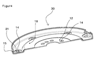
- FIG. 4 shows the joined sandwich component 30 in a perspective view. It can be seen, for example, in the central area that here the two output elements 10, 16 are superimposed, because because of the larger central hole 17 of the raised inner ring 18 of the overhead damping sheet already ends radially outward and you can the inner portion of the raised ring 12 of Base element with the holes 14 therefore in FIG. 4 recognize, since this area is exposed in the sandwich component 30. Furthermore you can see in FIG. 4 also that among the larger round holes 21 in concentric arrangement, the smaller round holes 14 are.
Applications Claiming Priority (1)
| Application Number | Priority Date | Filing Date | Title |
|---|---|---|---|
| DE201110001881 DE102011001881A1 (de) | 2011-04-07 | 2011-04-07 | Verfahren zur Herstellung eines Schwungrads |
Publications (2)
| Publication Number | Publication Date |
|---|---|
| EP2511566A2 true EP2511566A2 (fr) | 2012-10-17 |
| EP2511566A3 EP2511566A3 (fr) | 2014-11-19 |
Family
ID=46025390
Family Applications (1)
| Application Number | Title | Priority Date | Filing Date |
|---|---|---|---|
| EP12162454.8A Withdrawn EP2511566A3 (fr) | 2011-04-07 | 2012-03-30 | Procédé pour la fabrication d'une roue d'inertie |
Country Status (2)
| Country | Link |
|---|---|
| EP (1) | EP2511566A3 (fr) |
| DE (1) | DE102011001881A1 (fr) |
Cited By (2)
| Publication number | Priority date | Publication date | Assignee | Title |
|---|---|---|---|---|
| WO2016023715A1 (fr) * | 2014-08-13 | 2016-02-18 | Mühlhoff Umformtechnik GmbH | Procédé de fabrication d'un volant d'inertie |
| US11719321B2 (en) * | 2017-05-05 | 2023-08-08 | Mühlhoff Umformtechnik GmbH | Flywheel and method for producing a flywheel |
Families Citing this family (1)
| Publication number | Priority date | Publication date | Assignee | Title |
|---|---|---|---|---|
| DE202014011620U1 (de) | 2014-08-13 | 2023-11-30 | Mühlhoff Umformtechnik Gesellschaft mit beschränkter Haftung | Schwungrad |
Citations (2)
| Publication number | Priority date | Publication date | Assignee | Title |
|---|---|---|---|---|
| DE60008991T2 (de) | 1999-09-30 | 2005-01-05 | S.A. Defontaine | Schwungrad eines Verbrennungsmotors mit Anlasszahnkranz |
| DE60219270T2 (de) | 2001-12-04 | 2007-12-27 | Defontaine | Schalldämpfendes Anlasschwungrad |
Family Cites Families (7)
| Publication number | Priority date | Publication date | Assignee | Title |
|---|---|---|---|---|
| DE2907923C2 (de) * | 1979-03-01 | 1984-09-13 | Saljé, Ernst, Prof. Dr.-Ing., 2106 Bendestorf | Scheibenförmiges Objekt, insbesondere Werkzeug bzw. Werkzeug-Stammblatt |
| DE3622047A1 (de) * | 1986-07-01 | 1988-01-07 | Bayerische Motoren Werke Ag | Einteiliges getrieberad |
| EP0611229B1 (fr) * | 1993-02-11 | 1997-06-11 | Eastman Kodak Company | Volant modifié pour rouleaux de revêtement |
| EP0872358A1 (fr) * | 1997-04-16 | 1998-10-21 | Alusuisse Technology & Management AG | Roue de véhicule ferroviaire |
| DE10149704A1 (de) * | 2001-10-09 | 2003-04-10 | Zf Sachs Ag | Eingangsseitig zentral an einer Drehwelle oder Drehkomponente angebundene Kupplungseinrichtung in einem Kraftfahrzeug-Antriebsstrang |
| FR2833056B1 (fr) * | 2001-12-04 | 2004-02-20 | Defontaine Sa | Volant de demarrage avec fixation de la couronne dentee par sa surface radiale |
| EP1925847A1 (fr) * | 2006-11-22 | 2008-05-28 | Ford Global Technologies, LLC | Récipient contenant de la nourriture pour animaux |
-
2011
- 2011-04-07 DE DE201110001881 patent/DE102011001881A1/de not_active Withdrawn
-
2012
- 2012-03-30 EP EP12162454.8A patent/EP2511566A3/fr not_active Withdrawn
Patent Citations (2)
| Publication number | Priority date | Publication date | Assignee | Title |
|---|---|---|---|---|
| DE60008991T2 (de) | 1999-09-30 | 2005-01-05 | S.A. Defontaine | Schwungrad eines Verbrennungsmotors mit Anlasszahnkranz |
| DE60219270T2 (de) | 2001-12-04 | 2007-12-27 | Defontaine | Schalldämpfendes Anlasschwungrad |
Cited By (4)
| Publication number | Priority date | Publication date | Assignee | Title |
|---|---|---|---|---|
| WO2016023715A1 (fr) * | 2014-08-13 | 2016-02-18 | Mühlhoff Umformtechnik GmbH | Procédé de fabrication d'un volant d'inertie |
| CN106605081A (zh) * | 2014-08-13 | 2017-04-26 | 蒙霍夫成型技术有限公司 | 飞轮生产方法 |
| CN106605081B (zh) * | 2014-08-13 | 2020-07-24 | 蒙霍夫成型技术有限公司 | 飞轮生产方法 |
| US11719321B2 (en) * | 2017-05-05 | 2023-08-08 | Mühlhoff Umformtechnik GmbH | Flywheel and method for producing a flywheel |
Also Published As
| Publication number | Publication date |
|---|---|
| DE102011001881A1 (de) | 2012-10-11 |
| EP2511566A3 (fr) | 2014-11-19 |
Similar Documents
| Publication | Publication Date | Title |
|---|---|---|
| DE102008021498A1 (de) | Verfahren zur Fertigung eines Blattanschlusses eines Rotorblatts, ein Blattanschluss und ein Befestigungselement für einen Blattanschluss | |
| DE102006021843A1 (de) | Abstandsniet, Nietverbindung und Verfahren zu ihrer Herstellung | |
| DE102016115022A1 (de) | Bremsscheibe und Verfahren zu deren Herstellung | |
| EP2484924A1 (fr) | Liaison bout à bout et procédé de développement d'une liaison bout à bout | |
| DE19626688A1 (de) | Reibbelag für eine Kupplungsscheibe sowie damit ausgerüstete Kupplungsscheibe | |
| WO2016206878A1 (fr) | Poulie à courroie et disposition de la poulie à courroie sur un écrou de broche | |
| DE102010031841A1 (de) | Innennabe für ein Gelenk, Verfahren und Baukasten zur Herstellung | |
| EP2511566A2 (fr) | Procédé pour la fabrication d'une roue d'inertie | |
| WO2011042154A1 (fr) | Procédé de fabrication de disques pour un embrayage à friction et procédé de fabrication de garnitures de friction pour des disques d'un embrayage à friction | |
| EP3180547B1 (fr) | Methode pour la production d'un volant d'inertie | |
| EP2822759B1 (fr) | Tôle légère et construction comprenant une tôle légère | |
| EP0926407B1 (fr) | Joint de culasse | |
| DE102015202092A1 (de) | Verfahren zur Herstellung einer Fügeverbindung zwischen einem Gelenkgehäuse und einem Anbindungsbauteil, sowie verfahrensgemäß hergestelltes Fahrwerkbauteil | |
| EP2045483B1 (fr) | Procédé de fabrication d'un anneau de friction | |
| DE102017109726A1 (de) | Verfahren zur Herstellung eines Schwungrads | |
| DE102016202005A1 (de) | Nutzfahrzeugrad und Verwendung | |
| DE202014011620U1 (de) | Schwungrad | |
| EP3000543A1 (fr) | Procédé de fabrication d'une pièce en tôle à grande épaisseur de paroi et telle pièce en tôle | |
| EP1035349A2 (fr) | Support élastomérique avec butées axiales et méthode de fabrication d'un tel support | |
| DE102014205448A1 (de) | Hülseneinsatz | |
| DE102017208274A1 (de) | Verfahren zur Herstellung eines Bauteils mit integriertem Fügehilfselement und Halbzeug | |
| EP2409793A1 (fr) | Procédé de fabrication d'une pièce dotée d'une surface déterminée | |
| DE102009050817A1 (de) | Wickelbord für einen Lagerring, Wälzlager mit entsprechendem Lagerring sowie Verfahren zur Herstellung eines Lagerrings | |
| WO2008138286A2 (fr) | Procédé pour installer un élément d'assemblage ou fonctionnel sur un matériau plat et élément d'assemblage ou fonctionnel utilise a cet effet | |
| DE102017105319A1 (de) | Verfahren zur Herstellung einer Schalthülse für ein Zahnräder-Wechselgetriebe |
Legal Events
| Date | Code | Title | Description |
|---|---|---|---|
| PUAI | Public reference made under article 153(3) epc to a published international application that has entered the european phase |
Free format text: ORIGINAL CODE: 0009012 |
|
| AK | Designated contracting states |
Kind code of ref document: A2 Designated state(s): AL AT BE BG CH CY CZ DE DK EE ES FI FR GB GR HR HU IE IS IT LI LT LU LV MC MK MT NL NO PL PT RO RS SE SI SK SM TR |
|
| AX | Request for extension of the european patent |
Extension state: BA ME |
|
| PUAL | Search report despatched |
Free format text: ORIGINAL CODE: 0009013 |
|
| AK | Designated contracting states |
Kind code of ref document: A3 Designated state(s): AL AT BE BG CH CY CZ DE DK EE ES FI FR GB GR HR HU IE IS IT LI LT LU LV MC MK MT NL NO PL PT RO RS SE SI SK SM TR |
|
| AX | Request for extension of the european patent |
Extension state: BA ME |
|
| RIC1 | Information provided on ipc code assigned before grant |
Ipc: F16F 15/12 20060101AFI20141010BHEP Ipc: F16F 15/131 20060101ALI20141010BHEP |
|
| 17P | Request for examination filed |
Effective date: 20150512 |
|
| STAA | Information on the status of an ep patent application or granted ep patent |
Free format text: STATUS: THE APPLICATION IS DEEMED TO BE WITHDRAWN |
|
| 18D | Application deemed to be withdrawn |
Effective date: 20181002 |