EP2511566A2 - Method for producing a flywheel - Google Patents
Method for producing a flywheel Download PDFInfo
- Publication number
- EP2511566A2 EP2511566A2 EP12162454A EP12162454A EP2511566A2 EP 2511566 A2 EP2511566 A2 EP 2511566A2 EP 12162454 A EP12162454 A EP 12162454A EP 12162454 A EP12162454 A EP 12162454A EP 2511566 A2 EP2511566 A2 EP 2511566A2
- Authority
- EP
- European Patent Office
- Prior art keywords
- flywheel
- sheet metal
- joining process
- metal part
- base element
- Prior art date
- Legal status (The legal status is an assumption and is not a legal conclusion. Google has not performed a legal analysis and makes no representation as to the accuracy of the status listed.)
- Withdrawn
Links
Images


Classifications
-
- F—MECHANICAL ENGINEERING; LIGHTING; HEATING; WEAPONS; BLASTING
- F16—ENGINEERING ELEMENTS AND UNITS; GENERAL MEASURES FOR PRODUCING AND MAINTAINING EFFECTIVE FUNCTIONING OF MACHINES OR INSTALLATIONS; THERMAL INSULATION IN GENERAL
- F16F—SPRINGS; SHOCK-ABSORBERS; MEANS FOR DAMPING VIBRATION
- F16F15/00—Suppression of vibrations in systems; Means or arrangements for avoiding or reducing out-of-balance forces, e.g. due to motion
- F16F15/10—Suppression of vibrations in rotating systems by making use of members moving with the system
- F16F15/12—Suppression of vibrations in rotating systems by making use of members moving with the system using elastic members or friction-damping members, e.g. between a rotating shaft and a gyratory mass mounted thereon
- F16F15/1203—Suppression of vibrations in rotating systems by making use of members moving with the system using elastic members or friction-damping members, e.g. between a rotating shaft and a gyratory mass mounted thereon characterised by manufacturing, e.g. assembling or testing procedures for the damper units
-
- F—MECHANICAL ENGINEERING; LIGHTING; HEATING; WEAPONS; BLASTING
- F16—ENGINEERING ELEMENTS AND UNITS; GENERAL MEASURES FOR PRODUCING AND MAINTAINING EFFECTIVE FUNCTIONING OF MACHINES OR INSTALLATIONS; THERMAL INSULATION IN GENERAL
- F16F—SPRINGS; SHOCK-ABSORBERS; MEANS FOR DAMPING VIBRATION
- F16F15/00—Suppression of vibrations in systems; Means or arrangements for avoiding or reducing out-of-balance forces, e.g. due to motion
- F16F15/10—Suppression of vibrations in rotating systems by making use of members moving with the system
- F16F15/12—Suppression of vibrations in rotating systems by making use of members moving with the system using elastic members or friction-damping members, e.g. between a rotating shaft and a gyratory mass mounted thereon
- F16F15/131—Suppression of vibrations in rotating systems by making use of members moving with the system using elastic members or friction-damping members, e.g. between a rotating shaft and a gyratory mass mounted thereon the rotating system comprising two or more gyratory masses
- F16F15/13142—Suppression of vibrations in rotating systems by making use of members moving with the system using elastic members or friction-damping members, e.g. between a rotating shaft and a gyratory mass mounted thereon the rotating system comprising two or more gyratory masses characterised by the method of assembly, production or treatment
- F16F15/1315—Multi-part primary or secondary masses, e.g. assembled from pieces of sheet steel
Definitions
- the present invention relates to a method for producing a flywheel and a flywheel produced by this method.
- Flywheels in the context of the present invention are in particular flywheels for vehicles such as cars and trucks and both so-called automatic flywheels and manual flywheels (dual mass flywheels), as used for example in the automatic start / stop of motor vehicles, but also in vehicles flywheels used without start-stop automatic, so standard flywheels or flywheels for any other transmission variants.
- a damper-type flywheel in which a member made of a viscoelastic material is placed between the radial surface lying on the outer peripheral end portion of a carrier and the radial counter surface located on the inner peripheral end portion of a ring gear, under compressive stress in the radial and axial directions.
- This element is a ring seal, which is pressed into a groove of the carrier and thereby put under tension.
- the DE 600 08 991 T2 describes a flywheel of an internal combustion engine with starter sprocket.
- a flywheel of an internal combustion engine with starter sprocket In order to lower the noise level during starting, here is between a peripheral surface of a carrier of the flywheel and a complementary Peripheral surface of a flywheel mounted on the ring gear attached to a ring of a deformable elastomeric material by gluing.
- a liner of elastomer or plastomer may be secured to a radial surface between the carrier and sprocket which is approximately perpendicular to the peripheral surface so as to allow sliding contact between the carrier and the sprocket.
- the noise reduction should thus be achieved here by allowing a deformation of the ring gear radially to the shaft of the flywheel.
- the object of the present invention is to provide an alternative method for producing a flywheel, which leads to a flywheel with vibration-damping and sound-absorbing properties.
- Object of the present invention is also to provide a flywheel with these properties.
- the solution to this problem provides a method for producing a flywheel of the type mentioned above with the characterizing features of the main claim or a flywheel with the features of claim 11.
- the invention provides that a damping sheet metal part of a composite comprising a layer of sheet steel and a viscoelastic insulating layer in a joining process under pressure and partial deformation with a designed as a flywheel metallic base element permanently firmly connects to a sandwich component.
- an insulating layer and / or an adhesive with similar material properties can be used.
- the component designated there as a carrier for the flywheel is thus built up of several layers in sandwich construction, of which at least one layer, preferably an inner layer, is a viscoelastic insulating layer.
- the insulation thus does not take place between the carrier and ring gear of the flywheel, but virtually in the support member of the flywheel itself and thereby the entire surface, so that the support member substantially vibration over its entire surface extension and is formed sound-absorbing.
- a plurality of basically round elements with disc-shaped basic shape in the direction of their axis are joined so that they subsequently form a multilayer composite, wherein they connect with each other with their facing surfaces.
- Damping sheet metal part and base element each have approximately a similar disk-like geometric shape in the outline and they can also additionally each have corresponding deformations perpendicular to the plane of the disk shape. Due to the procedure according to the invention, the viscoelastic insulating layer is present after the joining process in all relevant surface areas of the composite component.
- the metallic base member is at least partially preformed in accordance with the shape of the flywheel and this perforations or punches are optionally made, preferably also preforming the damping sheet metal part of the composite at least partially according to the shape of the flywheel and optionally makes on this perforations or punched and then you both parts under pressure adds together, wherein in this joining process, the viscoelastic insulating layer of the sheet metal part facing the base member.
- the viscoelastic insulating layer With the metallic base element, so that a sandwich arises, consisting of the sheet metal layer of the base member and the sheet metal layer of the Dämpfungsblechteils, between which the vibration and noise damping viscoelastic layer is arranged.
- the entire assembly is pressed in this joining process so that the starting positions permanently connect firmly.
- the basic shape of the flywheel can be specified by the metallic base element and in the joining process, virtually the two-layer composite material clings to this basic form in a form-fitting manner, so that thereafter a flywheel in the desired shape with an at least three-layered construction is obtained. Since the viscoelastic layer or alternative layer now lies between two sheet metal layers, this has an insulating effect that prevents noise of any kind in the flywheel.
- the joining operation of the metallic base element and the damping sheet metal part made of composite material comprises a geometric deformation of the base element and / or of the damping sheet metal part.
- an additional fixation of both components is achieved by clipping the damping sheet metal part to the metallic base element.
- the joining process of the metallic base element and the sheet-metal part made of composite material comprises clinching.
- the clinch points an additional fixation of both components is achieved.
- the joining process of the metallic base element and the damping sheet metal part made of composite material comprises an additional fixing of both components by retaining tabs.
- the metallic base element preferably consists of a non-alloy cold-formable steel sheet.
- the viscoelastic insulating layer of the damping sheet member may comprise, for example, a polyacrylate resin.
- the composite material of the damping sheet member is usually provided so that the tacky viscoelastic layer is first protected by a protective film, which is then peeled off for the joining operation.
- the components can also be glued with adhesives, which are applied liquid before joining, to then cure to the permanently elastic state.
- the joining of the metallic base element with the two- or optionally multi-layer damping component is preferably carried out under a press, wherein the pressure to be exerted during the joining process naturally depends on the material pairing, but usually at least a contact pressure of about 2 bar is exerted on the components to be joined ,
- an external sprocket is also attached to the flywheel after the joining process.
- Other components of the flywheel can be riveted, welded or screwed, for example.
- the present invention furthermore relates to a flywheel provided for a starter of a motor vehicle, which flywheel is manufactured by a method according to one of claims 1 to 10.
- a flywheel can be used in a motor vehicle, for example in the area of a start / stop device. Due to the noise damping according to the invention, the annoying noise arising during starting is greatly reduced in an advantageous manner, which is particularly advantageous in motor vehicles with these devices, since occur significantly more often in these starting operations than in conventional vehicles. However, the use of the flywheels invention is also useful in motor vehicles with conventional starters.
- the base element is a preformed sheet metal part, for example made of sheet steel, which has various perforations and punched in accordance with the functions of the flywheel to be produced.
- the base element 10 has a central hole 11.
- the inner annular portion 12 of the base member 10 is raised, whereas the outer ring 13 adjoining it radially outwardly is lower.
- different round holes 14 are provided, as well as in the outer ring 13 various round holes 14 are present.
- the base member 10 has an outwardly of the plane of the outer ring approximately at right angles folded outer web 15.
- FIG. 2 is shown in perspective view the two-layer damping sheet metal part 16, which is joined in the manufacture of the flywheel with the base element 10 described above.
- This damping plate part 16 is a component made of a composite material and comprises an upper sheet metal layer 24 in the drawing and an in FIG. 2 unrecognizable viscoelastic layer 23, which is located on the underside of the sheet metal part 16 and thus in the joining process to the in FIG. 1 shown base element 10th is facing.
- the damping plate part 16 has a central hole 17, which is larger than the central hole 11 of the base member 10.
- the damping plate part 16 is thus an already preformed component whose basic shape is similar to that of the base element 10 described above, so that it is possible in the subsequent joining process, the two components 10 and 16 to bring one above the other and in a press to a the essential element of Flywheel forming component to add, as in FIG. 3 is shown, which shows the two components before the joining process.
- the viscoelastic insulating layer 23 of the damping sheet metal part 16 is below and thus it faces the base element 10. Reference is made to the enlarged view of a section of the damping plate part 16 according to the small illustration in FIG FIG. 3 directed to the left. If the two components are then joined under pressure, then the tacky viscoelastic layer connects to the metal sheet of the base element 10, so that a three-layer sandwich component is formed, consisting of the upper sheet metal layer of the damping element 16, the viscoelastic insulating layer 23 as an intermediate layer and the lower sheet metal layer of the Base element 10.
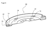
- FIG. 4 shows the joined sandwich component 30 in a perspective view. It can be seen, for example, in the central area that here the two output elements 10, 16 are superimposed, because because of the larger central hole 17 of the raised inner ring 18 of the overhead damping sheet already ends radially outward and you can the inner portion of the raised ring 12 of Base element with the holes 14 therefore in FIG. 4 recognize, since this area is exposed in the sandwich component 30. Furthermore you can see in FIG. 4 also that among the larger round holes 21 in concentric arrangement, the smaller round holes 14 are.
Abstract
Description
Die vorliegende Erfindung betrifft ein Verfahren zur Herstellung eines Schwungrads sowie ein nach diesem Verfahren hergestelltes Schwungrad.The present invention relates to a method for producing a flywheel and a flywheel produced by this method.
Schwungräder im Sinne der vorliegenden Erfindung sind insbesondere Schwungräder für Fahrzeuge wie PKWs und LKWs und zwar sowohl so genannte Automatik-Schwungräder als auch manuelle Schwungräder (Zweimassenschwungräder), wie sie beispielsweise in der Start/Stopp-Automatik von Kraftfahrzeugen verwendet werden, aber auch bei Fahrzeugen ohne Start-Stopp-Automatik verwendete Schwungräder, also Standard-Schwungräder oder auch Schwungräder für jegliche andere Getriebevarianten.Flywheels in the context of the present invention are in particular flywheels for vehicles such as cars and trucks and both so-called automatic flywheels and manual flywheels (dual mass flywheels), as used for example in the automatic start / stop of motor vehicles, but also in vehicles flywheels used without start-stop automatic, so standard flywheels or flywheels for any other transmission variants.
Nachteilig bei den bekannten Schwungrädern, die zum Anlassen verwendet werden, sind die störenden Geräusche, die beim Anlassvorgang entstehen.A disadvantage of the known flywheels that are used for starting, the disturbing noises that arise during the starting process.
In der
Die
Ausgehend von dem zuvor genannten Stand der Technik besteht die Aufgabe der vorliegenden Erfindung darin, ein alternatives Verfahren zur Herstellung eines Schwungrads zur Verfügung zu stellen, welches zu einem Schwungrad mit vibrationsdämmenden und geräuschdämmenden Eigenschaften führt. Aufgabe der vorliegenden Erfindung ist es weiterhin, ein Schwungrad mit diesen Eigenschaften zur Verfügung zu stellen.Starting from the aforementioned prior art, the object of the present invention is to provide an alternative method for producing a flywheel, which leads to a flywheel with vibration-damping and sound-absorbing properties. Object of the present invention is also to provide a flywheel with these properties.
Die Lösung dieser Aufgabe liefert ein Verfahren zur Herstellung eines Schwungrads der eingangs genannten Gattung mit den kennzeichnenden Merkmalen des Hauptanspruchs bzw. ein Schwungrad mit den Merkmalen des Anspruchs 11. Erfindungsgemäß ist vorgesehen, dass man ein Dämpfungsblechteil aus einem Verbundwerkstoff umfassend eine Schicht aus Stahlblech und eine viskoelastische Dämmschicht in einem Fügeprozess unter Druck und teilweiser Umformung mit einem als Schwungrad vorgesehenen metallischen Basiselement dauerhaft fest zu einem Sandwichbauteil verbindet. Alternativ kann auch eine Dämmschicht und /oder ein Klebstoff mit ähnlicher Materialeigenschaft eingesetzt werden.The solution to this problem provides a method for producing a flywheel of the type mentioned above with the characterizing features of the main claim or a flywheel with the features of
Im Gegensatz zum Stand der Technik wird somit das dort als Träger bezeichnete Bauteil für das Schwungrad aus mehreren Schichten in Sandwichbauweise aufgebaut, von denen mindestens eine Schicht, vorzugsweise eine innenliegende Schicht eine viskoelastische Dämmschicht ist. Die Dämmung erfolgt somit nicht zwischen Träger und Zahnkranz des Schwungrads, sondern quasi im Trägerbauteil des Schwungrads selbst und dabei vollflächig, so dass das Trägerbauteil im wesentlichen über seine gesamte Flächenerstreckung schwingungs- und geräuschdämpfend ausgebildet ist. Beim Fügevorgang werden mehrere im Prinzip runde Elemente mit scheibenförmiger Grundform in Richtung Ihrer Achse so gefügt, dass sie anschließend einen mehrschichtigen Verbund bilden, wobei sie sich mit ihren einander zugewandten Oberflächen miteinander verbinden. Dämpfungsblechteil und Basiselement haben jeweils etwa eine ähnliche scheibenartige geometrische Form im Umriss und sie können außerdem zusätzlich auch jeweils einander entsprechende Verformungen senkrecht zur Ebene der Scheibenform aufweisen. Bedingt durch die erfindungsgemäße Vorgehensweise ist die viskoelastische Dämmschicht nach dem Fügevorgang in allen relevanten Flächenbereichen des Verbundbauteils vorhanden.In contrast to the prior art, the component designated there as a carrier for the flywheel is thus built up of several layers in sandwich construction, of which at least one layer, preferably an inner layer, is a viscoelastic insulating layer. The insulation thus does not take place between the carrier and ring gear of the flywheel, but virtually in the support member of the flywheel itself and thereby the entire surface, so that the support member substantially vibration over its entire surface extension and is formed sound-absorbing. During the joining process, a plurality of basically round elements with disc-shaped basic shape in the direction of their axis are joined so that they subsequently form a multilayer composite, wherein they connect with each other with their facing surfaces. Damping sheet metal part and base element each have approximately a similar disk-like geometric shape in the outline and they can also additionally each have corresponding deformations perpendicular to the plane of the disk shape. Due to the procedure according to the invention, the viscoelastic insulating layer is present after the joining process in all relevant surface areas of the composite component.
Vorzugsweise wird dabei zunächst das metallische Basiselement mindestens teilweise entsprechend der Form des Schwungrads vorgeformt und an diesem werden gegebenenfalls Lochungen oder Ausstanzungen vorgenommen, wobei man bevorzugt das Dämpfungsblechteil aus dem Verbundwerkstoff ebenfalls mindestens teilweise entsprechend der Form des Schwungrads vorformt und gegebenenfalls an diesem Lochungen oder Ausstanzungen vornimmt und man dann beide Teile unter Druck miteinander fügt, wobei bei diesem Fügevorgang die viskoelastische Dämmschicht des Blechteils dem Basiselement zugewandt ist. Auf diese Weise verklebt quasi die viskoelastische Dämmschicht mit dem metallischen Basiselement, so dass eine Sandwichanordnung entsteht, bestehend aus der Blechlage des Basiselements und der Blechschicht des Dämpfungsblechteils, zwischen denen die Schwingungen und Geräusche dämpfende viskoelastische Schicht angeordnet ist. Die gesamte Anordnung wird bei diesem Fügevorgang so verpresst, dass sich die Ausgangslagen dauerhaft fest miteinander verbinden.Preferably, the metallic base member is at least partially preformed in accordance with the shape of the flywheel and this perforations or punches are optionally made, preferably also preforming the damping sheet metal part of the composite at least partially according to the shape of the flywheel and optionally makes on this perforations or punched and then you both parts under pressure adds together, wherein in this joining process, the viscoelastic insulating layer of the sheet metal part facing the base member. In this way, virtually bonds the viscoelastic insulating layer with the metallic base element, so that a sandwich arises, consisting of the sheet metal layer of the base member and the sheet metal layer of the Dämpfungsblechteils, between which the vibration and noise damping viscoelastic layer is arranged. The entire assembly is pressed in this joining process so that the starting positions permanently connect firmly.
Die Grundform des Schwungrads kann dabei von dem metallischen Basiselement vorgegeben werden und bei dem Fügeprozess schmiegt sich quasi das zweischichtige Verbundmaterial formschlüssig an diese Grundform an, so dass danach ein Schwungrad in der gewünschten Form mit einem mindestens dreischichtigen Aufbau erhalten wird. Da die viskoelastische Schicht oder alternative Schicht nun zwischen zwei Blechschichten liegt, hat diese eine dämmende Wirkung, die Störgeräusche jeglicher Art bei dem Schwungrad verhindert.The basic shape of the flywheel can be specified by the metallic base element and in the joining process, virtually the two-layer composite material clings to this basic form in a form-fitting manner, so that thereafter a flywheel in the desired shape with an at least three-layered construction is obtained. Since the viscoelastic layer or alternative layer now lies between two sheet metal layers, this has an insulating effect that prevents noise of any kind in the flywheel.
Zusätzlich kann man diverse Maßnahmen vorsehen, um eine bessere gegenseitige Fixierung der beiden Elemente in dem Fügevorgang zu erreichen. Dazu kann man beispielsweise vorsehen, dass der Fügevorgang von metallischem Basiselement und Dämpfungsblechteil aus Verbundwerkstoff eine geometrische Verformung des Basiselements und/oder des Dämpfungsblechteils umfasst. Beispielsweise kann vorgesehen sein, dass eine zusätzliche Fixierung beider Bauteile durch Einclipsen des Dämpfungsblechteils am metallischen Basiselement erzielt wird.In addition, one can provide various measures to achieve a better mutual fixation of the two elements in the joining process. For this purpose, it can be provided, for example, that the joining operation of the metallic base element and the damping sheet metal part made of composite material comprises a geometric deformation of the base element and / or of the damping sheet metal part. For example, it can be provided that an additional fixation of both components is achieved by clipping the damping sheet metal part to the metallic base element.
Beispielsweise kann es vorteilhaft sein, wenn der Fügevorgang von metallischem Basiselement und Blechteil aus Verbundwerkstoff ein Durchsetzfügen (Clinchen) umfasst. Durch die Clinchpunkte wird eine zusätzliche Fixierung beider Bauteile erzielt.For example, it may be advantageous if the joining process of the metallic base element and the sheet-metal part made of composite material comprises clinching. The clinch points an additional fixation of both components is achieved.
Ebenfalls vorteilhaft kann es sein, wenn der Fügevorgang von metallischem Basiselement und Dämpfungsblechteil aus Verbundwerkstoff eine zusätzliche Fixierung beider Bauteile durch Haltelaschen umfasst.It may also be advantageous if the joining process of the metallic base element and the damping sheet metal part made of composite material comprises an additional fixing of both components by retaining tabs.
Im Rahmen der vorliegenden Erfindung kommen grundsätzlich die verschiedensten Werkstoffpaarungen in Betracht. Vorzugsweise besteht das metallische Basiselement aus einem unlegierten kaltumformbaren Stahlblech. Die viskoelastische Dämmschicht des Dämpfungsblechteils kann zum Beispiel ein Polyacrylatharz umfassen. Das Verbundmaterial des Dämpfungsblechteils wird in der Regel so geliefert, dass die klebrige viskoelastische Schicht zunächst durch eine Schutzfolie geschützt ist, die dann für den Fügevorgang abgezogen wird. Die Bauteile können jedoch auch mit Klebstoffen verklebt werden, die vor dem Fügen flüssig aufgebracht werden, um dann auszuhärten bis zum dauerelastischen Zustand.In the context of the present invention, the most diverse material combinations come into consideration. The metallic base element preferably consists of a non-alloy cold-formable steel sheet. The viscoelastic insulating layer of the damping sheet member may comprise, for example, a polyacrylate resin. The composite material of the damping sheet member is usually provided so that the tacky viscoelastic layer is first protected by a protective film, which is then peeled off for the joining operation. However, the components can also be glued with adhesives, which are applied liquid before joining, to then cure to the permanently elastic state.
Das Fügen des metallischen Basiselements mit dem zwei- oder gegebenenfalls mehrschichtigen Dämpfungsbauteil geschieht bevorzugt unter einer Presse, wobei der beim Fügevorgang auszuübende Druck naturgemäß von der Werkstoffpaarung abhängt, wobei aber in der Regel mindestens ein Anpressdruck von etwa 2 bar auf die zu verbindenden Bauteile ausgeübt wird.The joining of the metallic base element with the two- or optionally multi-layer damping component is preferably carried out under a press, wherein the pressure to be exerted during the joining process naturally depends on the material pairing, but usually at least a contact pressure of about 2 bar is exerted on the components to be joined ,
Nach dem Fügevorgang schließen sich in der Regel weitere Arbeitsgänge an, beispielsweise Umform- und Beschneideoperationen, wobei derartige Verfahrensgänge natürlich auch vor dem Fügevorgang stattfinden können. In der Regel wird zudem nach dem Fügeprozess an dem Schwungrad ein äußerer Zahnkranz angebracht. Weitere Bauelemente des Schwungrads können beispielsweise angenietet, geschweißt oder angeschraubt werden.After the joining process, further operations usually follow, for example forming and trimming operations, whereby such process steps can of course also take place before the joining process. As a rule, an external sprocket is also attached to the flywheel after the joining process. Other components of the flywheel can be riveted, welded or screwed, for example.
Gegenstand der vorliegenden Erfindung ist weiterhin ein für einen Anlasser eines Kraftfahrzeugs vorgesehenes Schwungrad, welches nach einem Verfahren gemäß einem der Ansprüche 1 bis 10 hergestellt ist. Ein solches Schwungrad kann in einem Kraftfahrzeug beispielsweise im Bereich einer Start/Stopp-Einrichtung eingesetzt werden. Durch die erfindungsgemäße Geräuschdämpfung werden in vorteilhafter Weise die beim Anlassen entstehenden störenden Geräusche stark reduziert, was insbesondere bei Kraftfahrzeugen mit diesen Einrichtungen vorteilhaft ist, da bei diesen Anlassvorgänge erheblich häufiger vorkommen als bei konventionellen Fahrzeugen. Jedoch ist der Einsatz der erfindungsgemäßen Schwungräder ebenso bei Kraftfahrzeugen mit herkömmlichen Anlassern sinnvoll.The present invention furthermore relates to a flywheel provided for a starter of a motor vehicle, which flywheel is manufactured by a method according to one of claims 1 to 10. Such a flywheel can be used in a motor vehicle, for example in the area of a start / stop device. Due to the noise damping according to the invention, the annoying noise arising during starting is greatly reduced in an advantageous manner, which is particularly advantageous in motor vehicles with these devices, since occur significantly more often in these starting operations than in conventional vehicles. However, the use of the flywheels invention is also useful in motor vehicles with conventional starters.
Die in den U nteransprüchen beschriebenen Merkmale betreffen bevorzugte Weiterbildungen der erfindungsgemäßen Aufgabenlösung. Weitere Vorteile der vorliegenden Erfindung ergeben sich aus der nachfolgenden Detailbeschreibung.The features described in the subclaims relate to preferred developments of the task solution according to the invention. Further advantages of the present invention will become apparent from the following detailed description.
Nachfolgend wird die vorliegende Erfindung anhand von Ausführungsbeispielen unter Bezugnahme auf die beiliegenden Zeichnungen näher erläutert. Dabei zeigen:
-
Figur 1 eine perspektivische Ansicht eines metallischen Basiselements für ein erfindungsgemäßes Schwungrad; -
Figur 2 eine perspektivische Ansicht eines zweischichtigen Dämpfungsblechteils für ein erfindungsgemäßes Schwungrad; -
Figur 3 eine schematisch vereinfachte Schnittansicht von Basiselement und Dämpfungsblechteil während des Fügevorgangs; -
Figur 4 eine perspektivische Ansicht der miteinander verbundenen Elemente des Schwungrads nach dem Fügevorgang; -
Figur 5 eine Ansicht eines fertigen Schwungrads, welches nach dem erfindungsgemäßen Verfahren hergestellt wurde.
-
FIG. 1 a perspective view of a metallic base member for a flywheel according to the invention; -
FIG. 2 a perspective view of a two-layer damping sheet metal part for a flywheel according to the invention; -
FIG. 3 a simplified schematic sectional view of the base member and the damping plate part during the joining operation; -
FIG. 4 a perspective view of the interconnected elements of the flywheel after the joining operation; -
FIG. 5 a view of a finished flywheel, which was prepared by the method according to the invention.
Es wird nun nachfolgend zunächst auf die
In
Bei dem Fügeprozess unter Druck werden die beiden Bauteile 10, 16 nicht nur dauerhaft fest miteinander zu einem Sandwichbauteil verbunden, sondern sie können zusätzlich beispielsweise durch Durchsetzfügen (Clinchen) so verformt werden, dass sich eine bessere gegenseitige Fixierung ergibt.
Nach der Herstellung des Sandwichbauteils 30 erfolgen noch weitere Arbeitsgänge für die Herstellung des fertigen Schwungrads 26, welches in perspektivischer Darstellung in
- 1010
- Basiselementbase element
- 1111
- mittiges Lochcentral hole
- 1212
- erhabener innerer Ringraised inner ring
- 1313
- tiefer liegender äußerer Ringlower lying outer ring
- 1414
- Lochungenperforations
- 1515
- abgekanteter äußerer Stegbeveled outer bridge
- 1616
- DämpfungsblechteilDamping sheet metal part
- 1717
- mittiges Lochcentral hole
- 1818
- erhabener innerer Ringraised inner ring
- 1919
- dreieckige Lochungentriangular perforations
- 2020
- tiefer liegender äußerer Ringlower lying outer ring
- 2121
- runde Lochungenround holes
- 2222
- abgekanteter äußerer Stegbeveled outer bridge
- 2323
- viskoelastische Schichtviscoelastic layer
- 2424
- Blechschichtsheet metal layer
- 2525
- Zahnkranzsprocket
- 2626
- Schwungradflywheel
- 3030
- Sandwichbauteilsandwich component
Claims (12)
Applications Claiming Priority (1)
| Application Number | Priority Date | Filing Date | Title |
|---|---|---|---|
| DE201110001881 DE102011001881A1 (en) | 2011-04-07 | 2011-04-07 | Method for producing a flywheel |
Publications (2)
| Publication Number | Publication Date |
|---|---|
| EP2511566A2 true EP2511566A2 (en) | 2012-10-17 |
| EP2511566A3 EP2511566A3 (en) | 2014-11-19 |
Family
ID=46025390
Family Applications (1)
| Application Number | Title | Priority Date | Filing Date |
|---|---|---|---|
| EP12162454.8A Withdrawn EP2511566A3 (en) | 2011-04-07 | 2012-03-30 | Method for producing a flywheel |
Country Status (2)
| Country | Link |
|---|---|
| EP (1) | EP2511566A3 (en) |
| DE (1) | DE102011001881A1 (en) |
Cited By (2)
| Publication number | Priority date | Publication date | Assignee | Title |
|---|---|---|---|---|
| WO2016023715A1 (en) * | 2014-08-13 | 2016-02-18 | Mühlhoff Umformtechnik GmbH | Method for producing a flywheel |
| US11719321B2 (en) * | 2017-05-05 | 2023-08-08 | Mühlhoff Umformtechnik GmbH | Flywheel and method for producing a flywheel |
Families Citing this family (1)
| Publication number | Priority date | Publication date | Assignee | Title |
|---|---|---|---|---|
| DE202014011620U1 (en) | 2014-08-13 | 2023-11-30 | Mühlhoff Umformtechnik Gesellschaft mit beschränkter Haftung | flywheel |
Citations (2)
| Publication number | Priority date | Publication date | Assignee | Title |
|---|---|---|---|---|
| DE60008991T2 (en) | 1999-09-30 | 2005-01-05 | S.A. Defontaine | Flywheel of an internal combustion engine with starter ring gear |
| DE60219270T2 (en) | 2001-12-04 | 2007-12-27 | Defontaine | Sound-absorbing starting flywheel |
Family Cites Families (7)
| Publication number | Priority date | Publication date | Assignee | Title |
|---|---|---|---|---|
| DE2907923C2 (en) * | 1979-03-01 | 1984-09-13 | Saljé, Ernst, Prof. Dr.-Ing., 2106 Bendestorf | Disc-shaped object, in particular a tool or tool master sheet |
| DE3622047A1 (en) * | 1986-07-01 | 1988-01-07 | Bayerische Motoren Werke Ag | ONE-PIECE GEAR WHEEL |
| EP0611229B1 (en) * | 1993-02-11 | 1997-06-11 | Eastman Kodak Company | Improved flywheel for coating rolls |
| EP0872358A1 (en) * | 1997-04-16 | 1998-10-21 | Alusuisse Technology & Management AG | Railway vehicle wheel |
| DE10149704A1 (en) * | 2001-10-09 | 2003-04-10 | Zf Sachs Ag | Input-side clutch device has torque transmission device fixed for rotation to positive connecting element |
| FR2833056B1 (en) * | 2001-12-04 | 2004-02-20 | Defontaine Sa | STARTER FLYWHEEL WITH FIXING OF THE TOOTHED CROWN BY ITS RADIAL SURFACE |
| EP1925847A1 (en) * | 2006-11-22 | 2008-05-28 | Ford Global Technologies, LLC | Dampened Flywheel |
-
2011
- 2011-04-07 DE DE201110001881 patent/DE102011001881A1/en not_active Withdrawn
-
2012
- 2012-03-30 EP EP12162454.8A patent/EP2511566A3/en not_active Withdrawn
Patent Citations (2)
| Publication number | Priority date | Publication date | Assignee | Title |
|---|---|---|---|---|
| DE60008991T2 (en) | 1999-09-30 | 2005-01-05 | S.A. Defontaine | Flywheel of an internal combustion engine with starter ring gear |
| DE60219270T2 (en) | 2001-12-04 | 2007-12-27 | Defontaine | Sound-absorbing starting flywheel |
Cited By (4)
| Publication number | Priority date | Publication date | Assignee | Title |
|---|---|---|---|---|
| WO2016023715A1 (en) * | 2014-08-13 | 2016-02-18 | Mühlhoff Umformtechnik GmbH | Method for producing a flywheel |
| CN106605081A (en) * | 2014-08-13 | 2017-04-26 | 蒙霍夫成型技术有限公司 | Method for producing flywheel |
| CN106605081B (en) * | 2014-08-13 | 2020-07-24 | 蒙霍夫成型技术有限公司 | Flywheel production method |
| US11719321B2 (en) * | 2017-05-05 | 2023-08-08 | Mühlhoff Umformtechnik GmbH | Flywheel and method for producing a flywheel |
Also Published As
| Publication number | Publication date |
|---|---|
| DE102011001881A1 (en) | 2012-10-11 |
| EP2511566A3 (en) | 2014-11-19 |
Similar Documents
| Publication | Publication Date | Title |
|---|---|---|
| DE102008021498A1 (en) | Method for manufacturing a blade connection of a rotor blade, a blade connection and a fastening element for a blade connection | |
| DE102006021843A1 (en) | Rivet joint has spacer section between upsetting ridges, and is arranged between two sheet metal construction unit at certain distance to each other by spacer rivet in form of rivet shaft | |
| EP2484924A1 (en) | Joint connection and method for forming a joint connection | |
| DE19626688A1 (en) | Friction lining for car clutch discs - rests on annular support element, into which apertures between ID and OD are formed | |
| WO2016206878A1 (en) | Belt wheel, and arrangement of a belt wheel on a spindle nut | |
| DE102010031841A1 (en) | Inner hub for joint, comprises primary component comprising shank portion and secondary component comprising head portion that are mechanically connected together | |
| EP2511566A2 (en) | Method for producing a flywheel | |
| WO2011042154A1 (en) | Method for producing fins for a friction coupling and method for producing friction linings for fins of a friction coupling | |
| EP3180547B1 (en) | Method for flywheel production | |
| EP2822759B1 (en) | Lightweight plate, and construction comprising a lightweight plate | |
| EP0926407B1 (en) | Cylinder head gasket | |
| DE102015202092A1 (en) | A method for producing a joint connection between a joint housing and a connection component, and according to the method produced suspension component | |
| EP2045483B1 (en) | Method for producing a friction ring | |
| DE102017109726A1 (en) | Method for producing a flywheel | |
| DE102016202005A1 (en) | Commercial vehicle wheel and use | |
| DE202014011620U1 (en) | flywheel | |
| DE102010025389A1 (en) | Nail for connecting join parts, has nail shaft provided with profile portion, where peripheral portions of nail are evenly divided in range of profile portion and profile portion has extending peripheral portions with surface profile | |
| DE102009015025A1 (en) | roller bearing assembly | |
| EP3000543A1 (en) | Method for producing a sheet metal part with large wall thickness and such a sheet metal part | |
| EP1035349A2 (en) | Elastomeric support with axial end-stops and manufacturing process therefor | |
| DE102014205448A1 (en) | sleeve insert | |
| DE102017208274A1 (en) | Method for producing a component with integrated joining auxiliary element and semifinished product | |
| WO2017157387A1 (en) | Method for producing a shift sleeve for a variable-ratio gear transmission | |
| DE102009050817A1 (en) | Ring e.g. inner ring or outer ring, for taper roller bearing, has flange defining raceway, where flange has body repeatedly wound around bearing axis and consisting of wire, metal band, plastic band or rubber band | |
| WO2008138286A2 (en) | Method for application of a joint or function element to a planar material and joint or function element |
Legal Events
| Date | Code | Title | Description |
|---|---|---|---|
| PUAI | Public reference made under article 153(3) epc to a published international application that has entered the european phase |
Free format text: ORIGINAL CODE: 0009012 |
|
| AK | Designated contracting states |
Kind code of ref document: A2 Designated state(s): AL AT BE BG CH CY CZ DE DK EE ES FI FR GB GR HR HU IE IS IT LI LT LU LV MC MK MT NL NO PL PT RO RS SE SI SK SM TR |
|
| AX | Request for extension of the european patent |
Extension state: BA ME |
|
| PUAL | Search report despatched |
Free format text: ORIGINAL CODE: 0009013 |
|
| AK | Designated contracting states |
Kind code of ref document: A3 Designated state(s): AL AT BE BG CH CY CZ DE DK EE ES FI FR GB GR HR HU IE IS IT LI LT LU LV MC MK MT NL NO PL PT RO RS SE SI SK SM TR |
|
| AX | Request for extension of the european patent |
Extension state: BA ME |
|
| RIC1 | Information provided on ipc code assigned before grant |
Ipc: F16F 15/12 20060101AFI20141010BHEP Ipc: F16F 15/131 20060101ALI20141010BHEP |
|
| 17P | Request for examination filed |
Effective date: 20150512 |
|
| STAA | Information on the status of an ep patent application or granted ep patent |
Free format text: STATUS: THE APPLICATION IS DEEMED TO BE WITHDRAWN |
|
| 18D | Application deemed to be withdrawn |
Effective date: 20181002 |