EP2511535A2 - Dispositif de commande hydraulique - Google Patents
Dispositif de commande hydraulique Download PDFInfo
- Publication number
- EP2511535A2 EP2511535A2 EP20120163591 EP12163591A EP2511535A2 EP 2511535 A2 EP2511535 A2 EP 2511535A2 EP 20120163591 EP20120163591 EP 20120163591 EP 12163591 A EP12163591 A EP 12163591A EP 2511535 A2 EP2511535 A2 EP 2511535A2
- Authority
- EP
- European Patent Office
- Prior art keywords
- oil
- channel
- spool
- control device
- flow passage
- Prior art date
- Legal status (The legal status is an assumption and is not a legal conclusion. Google has not performed a legal analysis and makes no representation as to the accuracy of the status listed.)
- Withdrawn
Links
Images


Classifications
-
- F—MECHANICAL ENGINEERING; LIGHTING; HEATING; WEAPONS; BLASTING
- F01—MACHINES OR ENGINES IN GENERAL; ENGINE PLANTS IN GENERAL; STEAM ENGINES
- F01L—CYCLICALLY OPERATING VALVES FOR MACHINES OR ENGINES
- F01L1/00—Valve-gear or valve arrangements, e.g. lift-valve gear
- F01L1/34—Valve-gear or valve arrangements, e.g. lift-valve gear characterised by the provision of means for changing the timing of the valves without changing the duration of opening and without affecting the magnitude of the valve lift
- F01L1/344—Valve-gear or valve arrangements, e.g. lift-valve gear characterised by the provision of means for changing the timing of the valves without changing the duration of opening and without affecting the magnitude of the valve lift changing the angular relationship between crankshaft and camshaft, e.g. using helicoidal gear
- F01L1/3442—Valve-gear or valve arrangements, e.g. lift-valve gear characterised by the provision of means for changing the timing of the valves without changing the duration of opening and without affecting the magnitude of the valve lift changing the angular relationship between crankshaft and camshaft, e.g. using helicoidal gear using hydraulic chambers with variable volume to transmit the rotating force
-
- F—MECHANICAL ENGINEERING; LIGHTING; HEATING; WEAPONS; BLASTING
- F16—ENGINEERING ELEMENTS AND UNITS; GENERAL MEASURES FOR PRODUCING AND MAINTAINING EFFECTIVE FUNCTIONING OF MACHINES OR INSTALLATIONS; THERMAL INSULATION IN GENERAL
- F16K—VALVES; TAPS; COCKS; ACTUATING-FLOATS; DEVICES FOR VENTING OR AERATING
- F16K47/00—Means in valves for absorbing fluid energy
- F16K47/08—Means in valves for absorbing fluid energy for decreasing pressure or noise level and having a throttling member separate from the closure member, e.g. screens, slots, labyrinths
- F16K47/10—Means in valves for absorbing fluid energy for decreasing pressure or noise level and having a throttling member separate from the closure member, e.g. screens, slots, labyrinths in which the medium in one direction must flow through the throttling channel, and in the other direction may flow through a much wider channel parallel to the throttling channel
-
- F—MECHANICAL ENGINEERING; LIGHTING; HEATING; WEAPONS; BLASTING
- F01—MACHINES OR ENGINES IN GENERAL; ENGINE PLANTS IN GENERAL; STEAM ENGINES
- F01M—LUBRICATING OF MACHINES OR ENGINES IN GENERAL; LUBRICATING INTERNAL COMBUSTION ENGINES; CRANKCASE VENTILATING
- F01M1/00—Pressure lubrication
- F01M1/16—Controlling lubricant pressure or quantity
-
- F—MECHANICAL ENGINEERING; LIGHTING; HEATING; WEAPONS; BLASTING
- F01—MACHINES OR ENGINES IN GENERAL; ENGINE PLANTS IN GENERAL; STEAM ENGINES
- F01M—LUBRICATING OF MACHINES OR ENGINES IN GENERAL; LUBRICATING INTERNAL COMBUSTION ENGINES; CRANKCASE VENTILATING
- F01M1/00—Pressure lubrication
- F01M1/18—Indicating or safety devices
- F01M1/20—Indicating or safety devices concerning lubricant pressure
-
- F—MECHANICAL ENGINEERING; LIGHTING; HEATING; WEAPONS; BLASTING
- F04—POSITIVE - DISPLACEMENT MACHINES FOR LIQUIDS; PUMPS FOR LIQUIDS OR ELASTIC FLUIDS
- F04C—ROTARY-PISTON, OR OSCILLATING-PISTON, POSITIVE-DISPLACEMENT MACHINES FOR LIQUIDS; ROTARY-PISTON, OR OSCILLATING-PISTON, POSITIVE-DISPLACEMENT PUMPS
- F04C14/00—Control of, monitoring of, or safety arrangements for, machines, pumps or pumping installations
- F04C14/24—Control of, monitoring of, or safety arrangements for, machines, pumps or pumping installations characterised by using valves controlling pressure or flow rate, e.g. discharge valves or unloading valves
- F04C14/26—Control of, monitoring of, or safety arrangements for, machines, pumps or pumping installations characterised by using valves controlling pressure or flow rate, e.g. discharge valves or unloading valves using bypass channels
- F04C14/265—Control of, monitoring of, or safety arrangements for, machines, pumps or pumping installations characterised by using valves controlling pressure or flow rate, e.g. discharge valves or unloading valves using bypass channels being obtained by displacing a lateral sealing face
-
- F—MECHANICAL ENGINEERING; LIGHTING; HEATING; WEAPONS; BLASTING
- F15—FLUID-PRESSURE ACTUATORS; HYDRAULICS OR PNEUMATICS IN GENERAL
- F15B—SYSTEMS ACTING BY MEANS OF FLUIDS IN GENERAL; FLUID-PRESSURE ACTUATORS, e.g. SERVOMOTORS; DETAILS OF FLUID-PRESSURE SYSTEMS, NOT OTHERWISE PROVIDED FOR
- F15B11/00—Servomotor systems without provision for follow-up action; Circuits therefor
- F15B11/16—Servomotor systems without provision for follow-up action; Circuits therefor with two or more servomotors
- F15B11/161—Servomotor systems without provision for follow-up action; Circuits therefor with two or more servomotors with sensing of servomotor demand or load
- F15B11/162—Servomotor systems without provision for follow-up action; Circuits therefor with two or more servomotors with sensing of servomotor demand or load for giving priority to particular servomotors or users
-
- F—MECHANICAL ENGINEERING; LIGHTING; HEATING; WEAPONS; BLASTING
- F01—MACHINES OR ENGINES IN GENERAL; ENGINE PLANTS IN GENERAL; STEAM ENGINES
- F01L—CYCLICALLY OPERATING VALVES FOR MACHINES OR ENGINES
- F01L1/00—Valve-gear or valve arrangements, e.g. lift-valve gear
- F01L1/34—Valve-gear or valve arrangements, e.g. lift-valve gear characterised by the provision of means for changing the timing of the valves without changing the duration of opening and without affecting the magnitude of the valve lift
- F01L1/344—Valve-gear or valve arrangements, e.g. lift-valve gear characterised by the provision of means for changing the timing of the valves without changing the duration of opening and without affecting the magnitude of the valve lift changing the angular relationship between crankshaft and camshaft, e.g. using helicoidal gear
- F01L1/3442—Valve-gear or valve arrangements, e.g. lift-valve gear characterised by the provision of means for changing the timing of the valves without changing the duration of opening and without affecting the magnitude of the valve lift changing the angular relationship between crankshaft and camshaft, e.g. using helicoidal gear using hydraulic chambers with variable volume to transmit the rotating force
- F01L2001/34423—Details relating to the hydraulic feeding circuit
- F01L2001/34426—Oil control valves
- F01L2001/3443—Solenoid driven oil control valves
-
- F—MECHANICAL ENGINEERING; LIGHTING; HEATING; WEAPONS; BLASTING
- F01—MACHINES OR ENGINES IN GENERAL; ENGINE PLANTS IN GENERAL; STEAM ENGINES
- F01L—CYCLICALLY OPERATING VALVES FOR MACHINES OR ENGINES
- F01L1/00—Valve-gear or valve arrangements, e.g. lift-valve gear
- F01L1/34—Valve-gear or valve arrangements, e.g. lift-valve gear characterised by the provision of means for changing the timing of the valves without changing the duration of opening and without affecting the magnitude of the valve lift
- F01L1/344—Valve-gear or valve arrangements, e.g. lift-valve gear characterised by the provision of means for changing the timing of the valves without changing the duration of opening and without affecting the magnitude of the valve lift changing the angular relationship between crankshaft and camshaft, e.g. using helicoidal gear
- F01L1/3442—Valve-gear or valve arrangements, e.g. lift-valve gear characterised by the provision of means for changing the timing of the valves without changing the duration of opening and without affecting the magnitude of the valve lift changing the angular relationship between crankshaft and camshaft, e.g. using helicoidal gear using hydraulic chambers with variable volume to transmit the rotating force
- F01L2001/34423—Details relating to the hydraulic feeding circuit
- F01L2001/34426—Oil control valves
- F01L2001/34433—Location oil control valves
-
- F—MECHANICAL ENGINEERING; LIGHTING; HEATING; WEAPONS; BLASTING
- F01—MACHINES OR ENGINES IN GENERAL; ENGINE PLANTS IN GENERAL; STEAM ENGINES
- F01L—CYCLICALLY OPERATING VALVES FOR MACHINES OR ENGINES
- F01L1/00—Valve-gear or valve arrangements, e.g. lift-valve gear
- F01L1/34—Valve-gear or valve arrangements, e.g. lift-valve gear characterised by the provision of means for changing the timing of the valves without changing the duration of opening and without affecting the magnitude of the valve lift
- F01L1/344—Valve-gear or valve arrangements, e.g. lift-valve gear characterised by the provision of means for changing the timing of the valves without changing the duration of opening and without affecting the magnitude of the valve lift changing the angular relationship between crankshaft and camshaft, e.g. using helicoidal gear
- F01L1/3442—Valve-gear or valve arrangements, e.g. lift-valve gear characterised by the provision of means for changing the timing of the valves without changing the duration of opening and without affecting the magnitude of the valve lift changing the angular relationship between crankshaft and camshaft, e.g. using helicoidal gear using hydraulic chambers with variable volume to transmit the rotating force
- F01L2001/34423—Details relating to the hydraulic feeding circuit
- F01L2001/34436—Features or method for avoiding malfunction due to foreign matters in oil
- F01L2001/3444—Oil filters
-
- F—MECHANICAL ENGINEERING; LIGHTING; HEATING; WEAPONS; BLASTING
- F01—MACHINES OR ENGINES IN GENERAL; ENGINE PLANTS IN GENERAL; STEAM ENGINES
- F01L—CYCLICALLY OPERATING VALVES FOR MACHINES OR ENGINES
- F01L1/00—Valve-gear or valve arrangements, e.g. lift-valve gear
- F01L1/34—Valve-gear or valve arrangements, e.g. lift-valve gear characterised by the provision of means for changing the timing of the valves without changing the duration of opening and without affecting the magnitude of the valve lift
- F01L1/344—Valve-gear or valve arrangements, e.g. lift-valve gear characterised by the provision of means for changing the timing of the valves without changing the duration of opening and without affecting the magnitude of the valve lift changing the angular relationship between crankshaft and camshaft, e.g. using helicoidal gear
- F01L1/3442—Valve-gear or valve arrangements, e.g. lift-valve gear characterised by the provision of means for changing the timing of the valves without changing the duration of opening and without affecting the magnitude of the valve lift changing the angular relationship between crankshaft and camshaft, e.g. using helicoidal gear using hydraulic chambers with variable volume to transmit the rotating force
- F01L2001/3445—Details relating to the hydraulic means for changing the angular relationship
- F01L2001/34453—Locking means between driving and driven members
- F01L2001/34466—Locking means between driving and driven members with multiple locking devices
-
- F—MECHANICAL ENGINEERING; LIGHTING; HEATING; WEAPONS; BLASTING
- F01—MACHINES OR ENGINES IN GENERAL; ENGINE PLANTS IN GENERAL; STEAM ENGINES
- F01L—CYCLICALLY OPERATING VALVES FOR MACHINES OR ENGINES
- F01L1/00—Valve-gear or valve arrangements, e.g. lift-valve gear
- F01L1/34—Valve-gear or valve arrangements, e.g. lift-valve gear characterised by the provision of means for changing the timing of the valves without changing the duration of opening and without affecting the magnitude of the valve lift
- F01L1/344—Valve-gear or valve arrangements, e.g. lift-valve gear characterised by the provision of means for changing the timing of the valves without changing the duration of opening and without affecting the magnitude of the valve lift changing the angular relationship between crankshaft and camshaft, e.g. using helicoidal gear
- F01L1/3442—Valve-gear or valve arrangements, e.g. lift-valve gear characterised by the provision of means for changing the timing of the valves without changing the duration of opening and without affecting the magnitude of the valve lift changing the angular relationship between crankshaft and camshaft, e.g. using helicoidal gear using hydraulic chambers with variable volume to transmit the rotating force
- F01L2001/3445—Details relating to the hydraulic means for changing the angular relationship
- F01L2001/34453—Locking means between driving and driven members
- F01L2001/34473—Lock movement perpendicular to camshaft axis
-
- F—MECHANICAL ENGINEERING; LIGHTING; HEATING; WEAPONS; BLASTING
- F01—MACHINES OR ENGINES IN GENERAL; ENGINE PLANTS IN GENERAL; STEAM ENGINES
- F01L—CYCLICALLY OPERATING VALVES FOR MACHINES OR ENGINES
- F01L1/00—Valve-gear or valve arrangements, e.g. lift-valve gear
- F01L1/34—Valve-gear or valve arrangements, e.g. lift-valve gear characterised by the provision of means for changing the timing of the valves without changing the duration of opening and without affecting the magnitude of the valve lift
- F01L1/344—Valve-gear or valve arrangements, e.g. lift-valve gear characterised by the provision of means for changing the timing of the valves without changing the duration of opening and without affecting the magnitude of the valve lift changing the angular relationship between crankshaft and camshaft, e.g. using helicoidal gear
- F01L1/3442—Valve-gear or valve arrangements, e.g. lift-valve gear characterised by the provision of means for changing the timing of the valves without changing the duration of opening and without affecting the magnitude of the valve lift changing the angular relationship between crankshaft and camshaft, e.g. using helicoidal gear using hydraulic chambers with variable volume to transmit the rotating force
- F01L2001/3445—Details relating to the hydraulic means for changing the angular relationship
- F01L2001/34479—Sealing of phaser devices
-
- F—MECHANICAL ENGINEERING; LIGHTING; HEATING; WEAPONS; BLASTING
- F01—MACHINES OR ENGINES IN GENERAL; ENGINE PLANTS IN GENERAL; STEAM ENGINES
- F01L—CYCLICALLY OPERATING VALVES FOR MACHINES OR ENGINES
- F01L1/00—Valve-gear or valve arrangements, e.g. lift-valve gear
- F01L1/34—Valve-gear or valve arrangements, e.g. lift-valve gear characterised by the provision of means for changing the timing of the valves without changing the duration of opening and without affecting the magnitude of the valve lift
- F01L1/344—Valve-gear or valve arrangements, e.g. lift-valve gear characterised by the provision of means for changing the timing of the valves without changing the duration of opening and without affecting the magnitude of the valve lift changing the angular relationship between crankshaft and camshaft, e.g. using helicoidal gear
- F01L1/3442—Valve-gear or valve arrangements, e.g. lift-valve gear characterised by the provision of means for changing the timing of the valves without changing the duration of opening and without affecting the magnitude of the valve lift changing the angular relationship between crankshaft and camshaft, e.g. using helicoidal gear using hydraulic chambers with variable volume to transmit the rotating force
- F01L2001/3445—Details relating to the hydraulic means for changing the angular relationship
- F01L2001/34483—Phaser return springs
-
- F—MECHANICAL ENGINEERING; LIGHTING; HEATING; WEAPONS; BLASTING
- F15—FLUID-PRESSURE ACTUATORS; HYDRAULICS OR PNEUMATICS IN GENERAL
- F15B—SYSTEMS ACTING BY MEANS OF FLUIDS IN GENERAL; FLUID-PRESSURE ACTUATORS, e.g. SERVOMOTORS; DETAILS OF FLUID-PRESSURE SYSTEMS, NOT OTHERWISE PROVIDED FOR
- F15B13/00—Details of servomotor systems ; Valves for servomotor systems
- F15B13/02—Fluid distribution or supply devices characterised by their adaptation to the control of servomotors
- F15B13/022—Flow-dividers; Priority valves
-
- Y—GENERAL TAGGING OF NEW TECHNOLOGICAL DEVELOPMENTS; GENERAL TAGGING OF CROSS-SECTIONAL TECHNOLOGIES SPANNING OVER SEVERAL SECTIONS OF THE IPC; TECHNICAL SUBJECTS COVERED BY FORMER USPC CROSS-REFERENCE ART COLLECTIONS [XRACs] AND DIGESTS
- Y10—TECHNICAL SUBJECTS COVERED BY FORMER USPC
- Y10T—TECHNICAL SUBJECTS COVERED BY FORMER US CLASSIFICATION
- Y10T137/00—Fluid handling
- Y10T137/7722—Line condition change responsive valves
- Y10T137/7837—Direct response valves [i.e., check valve type]
- Y10T137/7847—With leak passage
-
- Y—GENERAL TAGGING OF NEW TECHNOLOGICAL DEVELOPMENTS; GENERAL TAGGING OF CROSS-SECTIONAL TECHNOLOGIES SPANNING OVER SEVERAL SECTIONS OF THE IPC; TECHNICAL SUBJECTS COVERED BY FORMER USPC CROSS-REFERENCE ART COLLECTIONS [XRACs] AND DIGESTS
- Y10—TECHNICAL SUBJECTS COVERED BY FORMER USPC
- Y10T—TECHNICAL SUBJECTS COVERED BY FORMER US CLASSIFICATION
- Y10T137/00—Fluid handling
- Y10T137/8593—Systems
- Y10T137/85978—With pump
- Y10T137/85986—Pumped fluid control
- Y10T137/86002—Fluid pressure responsive
Definitions
- This disclosure generally relates to a hydraulic control device.
- Patent reference 1 A type of hydraulic control device is disclosed in JP2009-299573A (hereinafter referred to as Patent reference 1), which includes a pump driven by a rotation of an engine for discharging oil, a valve timing control device actuated by an oil pressure provided by the oil supplied by the pump, and an engine lubricating device configured to lubricate engine parts by the oil supplied by the pump.
- the hydraulic control device disclosed in Patent reference 1 includes a valve device that is configured to supply oil to the valve timing control device on a priority basis when the oil pressure applied to the valve timing control device is low by limiting the oil flow amount from the pump to the engine lubricating device.
- a valve device that is configured to supply oil to the valve timing control device on a priority basis when the oil pressure applied to the valve timing control device is low by limiting the oil flow amount from the pump to the engine lubricating device.
- the valve device of the hydraulic control device disclosed in Patent reference 1 includes a valve component, a retainer, and a space corresponding to each of the valve component and the retainer to slide, the spaces, which leaves a room for improvement from a point of view in reducing size of the valve system or reducing space the hydraulic control device occupies on installment.
- Fig. 14 shows a known device considering the above improvement, in which a flow passage area regulation unit is reduced for the purpose of reducing the space the device occupies in the engine.
- the known hydraulic control device supplies the oil discharged from a pump 101 to a valve timing control device 102 and to a main gallery 108.
- a first channel 111 connects the pump 101 and the valve timing control device, and a second channel 113 branched from the first channel 111 connects to the main gallery 108.
- the second channel 113 is provided with a flow passage area regulation unit 103, which controls a dimension of a flow passage area of the second channel 113.
- the flow passage area regulation unit 103 includes a spool 131 and a biasing member 132.
- the spool 131 includes a first surface 131d subjected to a pressure and a second surface 131e subjected to the pressure. A surface area of the second surface 131e is smaller compared to that of the first surface 131d. The first surface 131d and the second surface 131e are formed to face each other with the second channel 113 therebetween. The biasing member 132 biases the spool 131 in a direction to close the second channel 113.
- the spool 131 receives a force similar to the oil pressure of the second channel 113 multiplied by an area difference between the first surface 131d subjected to a pressure and the second surface 131e subjected to the pressure and simultaneously receives a biasing force in the direction to close the second channel 113.
- the spool 131 receives the biasing force of the biasing member 132 predominately, which in turn moves the spool 131 in the direction to close the second channel 113 and reduces the dimension of the flow passage area of the second channel 113.
- the spool 131 moves against the biasing force of the biasing member 131 in the direction to open the second channel 113 and increases the dimension of the flow passage area of the second channel 113.
- the flow passage area regulation unit 103 controls the dimension of the flow passage area with the movements of the spool 131 alone. Having an area for the movements of the spool 131 alone, the hydraulic control device with the above configuration is advantageous in reducing the dimension of the flow passage area regulation unit 103.
- Fig. 15 is a cross-sectional view taken along a line XV-XV illustrating the spool 131 in a most closed state in which the spool regulates the flow passage area of the second channel 113 to the narrowest state, which is the state similar to the state shown in Fig. 14 .
- the flow passage area of the second channel 113 at this time is an arc area A not closed by the spool 131 out of the area of an opening 133a for a flow passage formed on a valve body 133.
- the area of the arc area A is determined so as to supply a minimal oil pressure used at the main gallery 108 in a downstream of the flow passage area regulation unit 103.
- a dimension of the arc area A is small.
- a slight positional change of the spool 131 affects largely the flow passage dimension of the second channel 113.
- errors in sum may result in the dimension of the arc area A to be substantially different from the predetermined dimension.
- a reliability of a pressure control of the hydraulic control device becomes less reliable. Reducing errors in each component by increasing processing accuracy in turn results in a disadvantage of increasing manufacturing cost of the hydraulic control device.
- a hydraulic control device includes a pump for discharging oil, a first predetermined portion configured to receive the oil discharged from the pump, a first channel establishing a communication between the pump and the first predetermined portion, a second channel branched from the first channel for supplying oil to a second predetermined portion arranged separately from the first predetermined portion, a flow passage area regulation unit arranged on the second channel, the flow passage area regulation unit equipped with a spool moving in a direction for increasing a flow passage area when an oil pressure in the second channel increases, the spool moving in a direction for decreasing a flow passage area when the oil pressure in the second channel decreases, and a bypass channel provided separately from a portion of the second channel where the spool disconnects the second channel, the bypass channel establishing a communication between an upstream side and a downstream side of the second channel relative to the flow passage area regulation unit, the bypass channel supplying oil to the second predetermined portion even in a closed state in which the spool disconnects the second channel.
- the bypass channel connects the upstream side and the downstream side of the second channel relative to the flow passage area regulation unit even when the spool is in the closed state in which the spool is in a position in the most closing direction.
- oil is supplied to the second predetermined portion in the downstream side of the flow passage area regulation unit via the bypass channel.
- the bypass channel processed to have a pipe diameter with an accuracy within the design tolerance provides the predetermined amount of oil to flow through the bypass channel.
- the bypass channel is provided separately from the portion where the spool disconnects the second channel so that the dimension of the flow passage area for the bypass channel may be retained to a constant predetermined dimension, without being affected by the dimension of the flow passage area of the second channel.
- Such configuration prevents from the oil pressure in the bypass channel to affect the movement of the spool, which in turn affects the dimension of flow passage area of the second channel.
- the hydraulic control device includes the bypass channel formed on the spool.
- the upstream side and the downstream side of the second channel may be connected with a simple processing on the spool.
- Such configuration restrains the size of the flow passage area regulation unit to increase and simultaneously makes the installation easier while providing the communicative connection between the upstream side and the downstream side of the second channel with a certainty.
- the hydraulic control device includes the bypass channel provided as an annular groove formed on an outer peripheral surface of the spool.
- the valve body When the bypass channel is formed on the outer peripheral surface of the spool, the valve body may be restrained from a size increase resulting from acquiring a space for the bypass channel. Restraining the valve body from the size increase is advantageous on the space the flow passage area regulation unit occupies on installment.
- the bypass channel formed as the annular groove on the outer periphery of the spool eliminates a consideration for deciding the correct circumferential direction relative to the valve body on positioning the spool to the valve body so that the installment process becomes simple.
- the oil pressure applies equally in the circumferential direction on the spool, so that the tilting of the spool may be prevented.
- the hydraulic control device includes the bypass channel formed on a valve body, which houses the spool.
- the upstream side and the downstream side of the second channel may be connected with a simple processing of the valve body.
- Such configuration restrains the size of the flow passage area regulation unit to increase and simultaneously makes the installation easier while providing the communicative connection between the upstream side and the downstream side of the second channel with the certainty.
- the hydraulic control device includes the bypass channel provided as an annular groove formed on the valve body, which houses the spool.
- Forming the bypass channel as the annular groove on the valve body eliminates the consideration for positioning the valve body relative to the valve housing in a certain direction for installation or for positioning the spool relative to the valve body in a certain direction for installation so that the installment process becomes simple while providing the communicative connection between the upstream side and the downstream side of the second channel with the certainty.
- the hydraulic control device includes the bypass channel having a first elongated groove formed on an outer peripheral surface of the valve body, which houses the spool, the first elongated groove connecting to the upstream side of the second channel, a second elongated groove formed on the outer peripheral surface of the valve body, the second elongated groove connecting to the downstream side of the second channel, and a through-hole formed on the valve body and connecting the first elongated groove and the second elongated groove.
- the first elongated groove and the second elongated groove are formed first on the outer peripheral surface of the valve body, then the through-hole connecting the first elongated groove and the second elongated groove is provided, thus the processing of the bypass channel is easy.
- the manufacturing process of the bypass channel becomes even easier.
- forming the bypass channel on the valve body may eliminate the positioning process for connecting the flow passage when installing the spool, so that the installment process becomes simple.
- the hydraulic control device includes the through-hole having a regulator portion with a smaller cross sectional area relative to a remaining portion of the through-hole.
- the amount of oil that flows through the bypass channel in the closed state may be controlled to the predetermined amount with the dimension of the regulator portion.
- the regulator portion limits the amount of oil that flows through the bypass channel to the predetermined amount, so that remaining oil may be used to apply the oil pressure to the spool 31.
- the oil pressure setting in which the spool 31 starts moving may be easily controlled with the dimension of the regulator portion. In other words, when the regulator portion having a predetermined dimension may be provided with an accuracy within the tolerance, other portions of the bypass channel may be processed with less accuracies for decreasing the manufacturing cost.
- the hydraulic control device includes the bypass channel formed on the valve housing to which the flow passage area regulation unit is provided.
- Forming the bypass channel on the valve housing eliminates the consideration for positioning, for example, the spool and the valve body in certain directions for installation so that the installment process becomes simple while providing the communicative connection between the upstream side and the downstream side of the second channel with the certainty.
- the valve body may be reduced in size without having the flow passage being formed.
- Fig. 1 is a general representation of a hydraulic control device according to embodiments disclosed here;
- Fig. 2 illustrates a state in which a flow passage area regulation unit is forced to remain in a fully open state
- Fig. 3 illustrates a state in which the flow passage area regulation unit is in a closed state
- Fig. 4 illustrates a sate immediately before the flow passage area regulation unit is to be opened
- Fig. 5 illustrates a state in which the flow passage area regulation unit is in an open state
- Fig. 6 illustrates a state in which the flow passage area regulation unit is in a fully open state
- Fig. 7A illustrates a relationship between an oil temperature and an actuation state (ON/OFF) of an oil control valve (OCV);
- Fig. 7B illustrates a relationship between an engine speed and an oil pressure in indicated portions when the flow passage area regulation unit is forced to remain in the fully open state
- Fig. 7C illustrates a relationship between the engine speed and the oil pressure in the indicated portions in which the flow passage area regulation unit shifts from the closed state to the fully open state;
- Fig. 8 illustrates a state in which the flow passage area regulation unit according to a second embodiment is in the closed state
- Fig. 9 illustrates a state in which the flow passage area regulation unit according to the second embodiment is in the state immediately before the flow passage area regulation unit is to be opened;
- Fig. 10 is a cross-sectional view taken along X-X in Fig. 8 ;
- Fig. 11 illustrates a state in which a flow passage area regulation unit according to a third embodiment is in the closed state
- Fig. 12 illustrates a state in which the flow passage area regulation unit according to the third embodiment is in the state immediately before the flow passage area regulation unit is to be opened;
- Fig. 13 is a cross-sectional view taken along XIII-XIII in Fig. 11 ;
- Fig. 14 illustrates a general representation of a known hydraulic control device
- Fig. 15 is a cross-sectional view taken along XV-XV in Fig. 14 .
- a valve timing control device 2 adapted for controlling intake valves serves as a first predetermined portion.
- the hydraulic control device includes a pump 1 driven by a rotation of an engine and the valve timing control device 2 in which a relative rotational phase changes by a supply or a discharge of oil.
- the valve timing control device 2 operates with the supply or the discharge of oil controlled by an oil control valve (OCV) 5.
- OCV oil control valve
- the pump 1 and the oil control valve (OCV) 5 are connected with an oil passage 11A for discharging oil.
- the valve timing control device 2 and the oil control valve (OCV) 5 are connected with an oil passage 12A for an advanced angle control and an oil passage 12B for a retarded angle control.
- the oil passage 11A for discharging oil, the oil passage 12A for the advanced angle control, and the oil passage 12B for the retarded angle control each serves as a first channel.
- An oil passage 13 for a lubricating oil which serves as a second channel, branches from the oil passage 11A for discharging oil and supplies oil to a main gallery 8, which serves as a second predetermined portion.
- the oil passage 13 for the lubricating oil is provided with a flow passage area regulation unit 3 for controlling a dimension of the flow passage area.
- Each of the oil passages are formed, for example, on a cylinder case of an engine.
- the pump 1 according to the first embodiment will be described next.
- a rotational driving power of a crankshaft is transmitted to the pump 1, which in turn drives the pump 1 mechanically for discharging oil.
- the pump 1 sucks in oil retained in an oil pan 1a and discharges the oil into the oil passage 11A for discharging oil, as shown in Fig. 1 .
- the oil passage 11A for discharging oil is provided with an oil filter 6 that filtrates dirt, sludge, small objects and the like, which an oil strainer does not filtrate.
- the oil filtered by the oil filter 6 is supplied to the valve timing control device 2 and the main gallery 8.
- the main gallery 8 refers to sliding members in the engine in general, for example, a piston, a cylinder, a bearing for the crankshaft and the like.
- the oil discharged from the valve timing control device 2 is returned to the oil pan 1a via the oil control valve (OCV) 5 and an oil return passage 11 B.
- OCV oil control valve
- the oil supplied to the main gallery 8 is collected in the oil pan 1a via engine cover portions and the like.
- the oil leaked from the valve timing control device 2 is collected in the oil pan 1a also via engine cover portions and the like.
- the valve timing control device 2 includes a housing 21 that synchronously-rotates relative to the crankshaft of the engine and an inner rotor 22 having a same center axis X as the housing 21 and synchronously-rotates relative to a camshaft 92.
- the valve timing control device 2 includes a locking mechanism 27 configured to restrain a relative rotational phase of the inner rotor 22 relative to the housing 21 to a most retarded angle phase by restraining a relative rotational movement of the inner rotor 22 relative to the housing 21.
- the housing 21 and the inner rotor 22 of the valve timing control device 2 will be described next in detail.
- the inner rotor 22 is mounted on an end portion of the camshaft 92.
- the housing 21 includes a front plate 21a on a side opposite to which the camshaft 92 is connected, an outer rotor 21b provided with timing sprockets 21 d being integrated, and a rear plate 21c on a side to which the camshaft 92 is connected.
- the outer rotor 21b is equipped outward of the inner rotor 22 and is sandwiched between the front plate 21a and the rear plate 21c. Bolts or means alike connect the front plate 21a, the outer rotor 21b, and the rear plate 21c.
- the rotational drive power is generated and is transmitted to the timing sprocket 21d via a power transmission member 93, which in turn rotationally drives the housing 21 in rotational directions S shown in Fig. 2 .
- the rotational drive of the housing 21 rotationally drives the inner rotor 22 in the rotational directions S so that the camshaft 92 rotates.
- a cam provided on the camshaft 92 is configured to press down and opens an intake valve of the engine.
- three fluid pressure chambers 24 are formed with the outer rotor 21b and the inner rotor 22.
- a plurality of vanes 22a are formed on the inner rotor 22 along the rotational directions S to project outward in a radial direction with each vane 22 being separated by a spacing therebetween.
- Each of the vanes 22a is configured to be disposed within the corresponding fluid pressure chamber 24.
- Each of the fluid pressure chambers 24 is separated with the corresponding vane 22a to form a chamber 24a for the advanced angle control and a chamber 24b for the retarded angle control, which are arranged along the rotational direction S.
- passages 25 in communication with the chambers 24a for the advanced angle control are formed on the inner rotor 22 and the camshaft 92 such that each of the passages 25 connects to the corresponding chamber 24a for the advanced angle control.
- Passages 26 in communication with the chambers 24b for the retarded angle control are formed on the inner rotor 22 and the camshaft 92 such that each of the passages 26 connects to a corresponding chamber 24b for the retarded angle control.
- the passages 25 in communication with the chambers 24a for the advanced angle control connect to the oil passage 12A for the advanced angle control that connects to the control valve (OCV) 5.
- the passages 26 in communication with the chambers 24b for the retarded angle control connect to the oil passage 12B for the retarded angle control that connects to the oil control valve (OCV) 5.
- a torsion spring 23 is arranged to relate the inner rotor 22 and the front plate 21a.
- the torsion spring 23 biases the inner rotor 22 in an advanced angle direction S1 so as to work against an average phase change force generated by a change in a cam torque that works in a retarded angle direction S2.
- the relative rotational phase of the inner rotor 22 may be shifted smoothly and swiftly in the advanced angle direction S1 to be described later.
- the locking mechanism 27 of the valve timing control device 2 will be described next in detail.
- the locking mechanism 27 restrains the relative rotational phase of the inner rotor 22 to the most retarded angle phase by retaining the housing 21 and the inner rotor 22 in a predetermined relative position.
- the configuration described above provides an appropriate engine start.
- the inner rotor 22 is prevented from moving rapidly back and forth in axial directions, which occurs at the engine start, during an idling state, and the similar situations, when a phase change force is generated by the changes in the cam torque.
- the locking mechanism 27 includes two locking members 27a in a plate form, a locking recess 27b, and a passage 28 in communication with the locking mechanism 27.
- the locking recess 27b having a predetermined length in a direction of a relative rotation, is formed on an outer peripheral surface of the inner rotor 22.
- the locking members 27a are arranged at containment portions formed on the outer rotor 21b such that project or retreat in the radial directions with respect to the locking recess 27b.
- the locking members 27a are constantly biased inward in the radial direction, that is toward the locking recess 27b.
- the passage 28 in communication with the locking mechanism 27 connects the locking recess 27b and the passages 25 in communication with chambers 24a for the advanced angle control.
- the locking recess 27b is supplied with oil similarly.
- the oil is discharged from the chambers 24a for the advanced angle control, the oil is discharged from the locking recess 27b likewise.
- each of the locking members 27a When the oil is discharged from the locking recess 27b, each of the locking members 27a may project into the locking recess 27b. As shown in Fig. 2 , when both of the locking members 27a enter the locking recess 27b, each of the locking members 27a engages with a corresponding end in the circumferential direction of the locking recess 27b. As a result, the relative rotational movement of the inner rotor 22 relative to the housing 21 is restrained and restrains the relative rotational phase of the inner rotor 22 to the most retarded angle phase. As shown in Fig.
- both of the locking members 27a retreat from the locking recess 27b so that the relative rotational phase of the inner rotor 22 shifts to an unrestrained state, that is to a state in which the inner rotor 22 may freely make the relative rotational movement.
- a state in which the locking mechanism 27 is restraining the relative rotational phase of the inner rotor 22 to the most retarded angle phase is referred to as a "locked state” and a state being released from the locked state is referred to as an "unlocked state.”
- the oil control valve (OCV) 5 is electromagnetically controlled.
- the oil control valve (OCV) 5 controls an oil supply, an oil discharge, and an interruption of the oil supply or of the oil discharge in the passages 25 in communication with the chambers 24a for the advanced angle control and in the passages 26 in communication with the chambers 24b for the retarded angle control.
- the oil control valve (OCV) 5 adopts a spool system and operates based on an electricity supply amount controlled by an engine control unit (ECU) 7.
- ECU engine control unit
- the oil control valve (OCV) 5 provides, for example, a state in which the oil is supplied to the oil passage 12A for the advanced angle control and the oil is discharged from the oil passage 12B for the retarded angle control, a state in which the oil is discharged from the oil passage 12A for the advanced angle control and the oil is supplied to the oil passage 12B for the retarded angle control, and a state in which the oil supply or the oil discharge in the oil passage 12A for the advanced angle control and the oil passage 12B for the retarded angle control is interrupted.
- a control operation in which the oil passage 12A for the advanced angle control being supplied with oil and the oil in the oil passage 12B for the retarded angle control being discharged is referred to as the "advanced angle control.”
- the vanes 22a make the relative rotational movement in the advanced angle direction S1 relative to the outer rotor 21b so that the relative rotational phase of the inner rotor 22 shifts toward the advanced angle.
- a control operation in which the oil in the oil passage 12A for the advanced angle control being discharged and the oil passage 12B for the retarded angle control being supplied with oil is referred to as the "retarded angle control.”
- the vanes 22a make the relative rotational movement in the retarded angle direction S2 relative to the outer rotor 21b so that the relative rotational phase of the inner rotor 22 shifts toward the retarded angle.
- the relative rotational phase of the inner rotor 22 may be retained in an arbitrary phase.
- the oil control valve (OCV) 5 is configured so that supplying power to the oil control valve (OCV) 5 makes the advanced angle control possible and cutting the power supply to the oil control valve (OCV) 5 makes the retarded angle control possible.
- a valve opening setting for the oil control valve (OCV) 5 is controlled with a duty ratio of the electricity supplied to the electromagnetic solenoid of the oil control valve (OCV) 5, which makes a subtle adjustment of an oil supply amount and an oil discharge amount possible.
- the oil control valve (OCV) 5 controls the oil pressure applied to the vanes 22a by supplying oil to, discharging oil from, or retaining the amount of oil in the chambers 24a for the advanced angle control and the chambers 24b for the retarded angle control.
- OCV oil control valve
- the inner rotor 22 makes a smooth relative rotational movement relative to the housing 21 in a predetermined range with the center axis X as an axis.
- Said predetermined range in which the inner rotor 22 makes the relative rotational movement relative to housing 21, which corresponds to a phase difference between the most advanced angle phase and the most retarded angle phase may also be regarded as the range in which each of the vanes 22a makes a positional change within the corresponding fluid pressure chamber 24.
- the state in which a volume of the chambers 24a for the advanced angle control becomes maximal is regarded as the most advanced angle phase and the state in which a volume of the chambers 24b for the retarded angle control becomes maximal is regarded as the most retarded angle phase.
- the valve timing control device 2 is equipped with a crank angle sensor for detecting a rotational angle of the crankshaft of the engine and a camshaft angle sensor for detecting a rotational angle of the camshaft 92.
- the engine control unit (ECU) 7 detects the relative rotational phase of the valve timing control device 2 from the detection results of the crank angle sensor and the camshaft angle sensor.
- the engine control unit (ECU) 7 is equipped with a signal communication system for receiving information, for example, whether an ignition key is operated in an ON or OFF state, or an oil temperature detected by an oil temperature sensor.
- control information for controlling the relative rotational phase of the valve timing control device 2 to an optimal state appropriate to an operational condition of the engine is stored. From the control information above combined with operational information, for example, engine speed and a coolant temperature, the engine control unit (ECU) 7 controls the relative rotational phase of the valve timing control device 2.
- the valve timing control device 2 In a state before the engine is started, the valve timing control device 2 is in the locked state by the locking mechanism 27, as shown in Fig. 2 .
- the ignition key When the ignition key is operated in the ON state, a cranking begins and the engine starts in a state where the relative rotational phase of the valve timing control device 2 is restrained to the most retarded angle phase.
- the state of the engine shifts to the idling state, warming of a catalyst begins. After the warming of the catalyst ends and when an acceleration pedal is pressed, the power is supplied to the oil control valve (OCV) 5 for the advanced angle control, so as to shift the relative rotational phase of the valve timing control device 2 in the advanced angle direction S1.
- OCV oil control valve
- valve timing control device 2 may shift the relative rotational phase freely to states as shown in Figs. 4 to 6 according to the supply of oil to the chambers 24a for the advanced angle control. Thereafter, the relative rotational phase of the valve timing control device 2 shifts between the most advanced angle phase and the most retarded angle phase in response to a load on the engine, the engine speed, and the like.
- the engine shifts to the idling state, in which the relative rotational phase of the valve timing control device 2 is in the most retarded angle phase.
- the idling state at least the locking member 27a in the direction of the advanced angle is projected into the locking recess 27b.
- the inner rotor 22 moves rapidly back and forth in circumference directions with the changes in the cam torque, which in turn makes the locking member 27a in the direction of the retarded angle also to project into the locking recess 27b and brings the valve timing control device 2 to the locked state, so that a next engine start operation may begin in a suitable state.
- the flow passage area regulation unit 3 includes a spool 31 configured to move orthogonally relative to the oil passage 13 for the lubricating oil, as shown in Figs. 2 to 6 .
- the spool 31 includes a large diameter portion 31a in a cylinder form, a small diameter portion 31b in a cylinder form having a smaller diameter than the diameter of the large diameter portion 31a, and a connecting portion 31c.
- the connecting portion 31c connects the central axis portions of each of the large diameter portion 31a and the small diameter portion 31b. at the central axis portion of each.
- a first surface 31d subjected to a pressure is a surface on the large diameter portion 31a, the surface that faces the small diameter portion 31b.
- a second surface 31e subjected to the pressure is a surface on the small diameter portion 31b, the surface that faces the large diameter portion 31a.
- the connecting portion 31c is formed with an annular space 36 around the periphery.
- the annular space 36 functions as a channel for oil to flow through the oil passage 13 for the lubricating oil, when the spool 31 is not closing the oil passage 13 for the lubricating oil, as shown in Fig. 2 .
- the large diameter portion 31a of the spool 31 is formed with a space having an open end such that together with a valve body 33 housing the spool 31 forms a space 37 for containing a spring 32 where the spring 32 is retained.
- the spring 32 constantly biases the spool 31 in a direction to reduce the dimension of the flow passage area of the oil passage 13 for the lubricating oil.
- the direction in which the spool 31 reduces the dimension of the flow passage area of the oil passage 13 for the lubricating oil, which is upward in Fig. 2 is referred to as a "closing direction"
- the direction in which the spool 31 increases the dimension of the flow passage area of the oil passage 13 for the lubricating oil, which is downward in Fig. 2 is referred to as an "opening direction.”
- the valve body 33 includes a main body 34 and a plug member 35.
- the main body 34 is formed with openings 34a for the flow passage in two locations on a sidewall thereof, which connect with the oil passage 13 for the lubricating oil.
- a state in which the spool 31 is moved to an end in the opening direction and the openings 34a for the flow passage being fully open is referred to as a "fully open state” as shown in Figs. 2 and 6 .
- a state in which the spool 31 is moved to an end in the closing direction and the openings 34a for the flow passage are closed by the spool 31 is, hereinafter, referred to as a "closed state" as shown in Fig. 3 .
- FIG. 5 Another state in which the openings 34a for the flow passage are partially open is, hereinafter, referred to as an "open state", as shown in Fig. 5 .
- FIG. 5 Yet another state in which the spool 31 has moved in the opening direction from the closed state and where the spool 31 is at a position immediately before the openings 34a for the flow passage are to be opened is, hereinafter, referred to as a "state immediately before the open state", as shown in Fig. 4 .
- a state in between Figs. 3 and 4 in which the spool 31 has moved from the end in the closing direction toward the opening direction however where the openings 34a for the flow passage are still closed by the spool 31 is, hereinafter, referred to as a "cut off state.”
- the plug member 35 is threaded and attaches to a threaded end of the main body 34 of the valve body 33 by screwing.
- the spool 31 and the spring 32 are housed inside the valve body 33.
- the space 37 for containing the spring 32 is an enclosed space, the spool 31 may not move smoothly when the spool 31 moves in the opening direction. Therefore, the plug member 35 is provided with a vent 35a that opens the space 37 for containing the spring 32 to atmosphere so that the spool 31 moves smoothly.
- a dimension of the first surface 31 d of the spool 31 subjected to the pressure is larger than the dimension of the second surface 31e subjected to the pressure.
- the spool 31 receives a force, hereinafter referred to as the force Fs, in the opening direction, which calculates to the oil pressure of the oil passage 13 for the lubricating oil multiplied by an difference in area determined by subtracting the area of the second surface 31e subjected to the pressure from the area of the first surface 31 d subjected to the pressure.
- the spool 31 also receives a biasing force from the spring 32, hereinafter referred to as the biasing force Fp, in the closing direction.
- a static frictional force hereinafter referred to as the static frictional force Fsf
- the static frictional force Fsf works on the spool 31 in the closing direction as a resistive force that is against the movement of the spool 31 in the opening direction.
- an amount to which the large diameter portion 31a of the spool 31 blocks the oil passage 13 for the lubricating oil changes, so that the dimension of the flow passage area for the oil passage 13 for the lubricating oil is controlled.
- a supply passage 34c is formed on the main body 34 of the valve body 33 for the purpose of generating the force Fs by supplying oil to the annular space 36 from the oil passage 13 for the lubricating oil.
- the oil pressure generated with the oil supplied to the annular space 36 needs to be applied to the whole area of the first surface 31d subjected to the pressure. Therefore, an initiation space 38 is provided between the first surface 31d subjected to the pressure and the main body 34 of the valve body 33, so that the oil may apply pressure on the first surface 31d subjected to the pressure even in the closed state.
- the flow passage area regulation unit 3 is retained in the fully open state under a certain condition to be described later in detail.
- the hydraulic control device according to the first embodiment is provided with an opening 34b for an actuation at an end portion of the main body 33 of the valve body 33, so that an oil passage 14 for the actuation, which is branched from the oil passage 12B for the retarded angle control, connects to the opening 34b for the actuation.
- the oil pressure from the oil passage 14 for the actuation is configured to apply to the whole area of the back surface of the second surface 31e subjected to the pressure. As a result, a large force is easily generated so that the flow passage area regulation unit 3 may be retained in the fully open state as shown in Fig. 2 .
- the fully open state being retained as described above is, hereinafter, referred to as a "forced fully open state.”
- a valve housing 41 in which the valve body 33 is installed is formed with an oil passage 15 for a communicative connection of the upstream side and the downstream side of the oil passage 13 for the lubricating oil relative to the flow passage area regulation unit 3.
- the oil passage 15 for the communicative connection serves as a bypass channel.
- the oil passage 15 for the communicative connection processed to have a pipe diameter with an accuracy within the design tolerance provides the predetermined amount of oil to the main gallery 8 during the cut off state, which is the state between the closed state as shown in Fig. 3 and the state immediately before the open sate as shown in Fig. 4 ,
- the spool 31 slides inside the valve body 33 with an effect of the oil pressure in the oil passage 13 for the lubricating oil or with the effect of the oil pressure in the oil passage 14 for the actuation in addition to the oil pressure in the oil passage 13 for the lubricating oil, so that the dimension of the flow passage area of the oil passage 13 for the lubricating oil is controlled.
- FIG. 7A to 7C indicates the state of the hydraulic control device described in Figs. 2 to 6 , respectively.
- II indicates the hydraulic control device in the forced fully open state
- III indicates the closed state
- between III to IV indicates the cut off state
- IV indicates the state immediately before the open state
- V indicates the open state
- VI indicates the fully open state.
- the valve timing control device 2 without an operational necessity, does not use oil for generating the oil pressure.
- the main gallery 8 starts functioning immediately after the engine start, and starts using oil for lubrication. Therefore, when the oil temperature is lower than a first predetermined temperature T1, the oil control valve (OCV) 5 is in the OFF state in which the power is not supplied, as shown in Fig. 7A .
- the state of the oil control valve (OCV) 5 is retained in the retarded angle control, in which the oil passage 12B for the retarded angle control and the oil passage 11A for discharging oil connect and the oil passage 12A for the advanced angle control and the oil return passage 11 B connect.
- the chambers 24b for the retarded angle control is provided with oil regardless of the valve timing control device 2 being in the locked state and the oil pressure in the oil passage 12B for the retarded angle control increases.
- the increased oil pressure is applied to the back surface of the second surface 31e subjected to the pressure via the passage 14 for the actuation, so that the spool 31 moves in the opening direction.
- the flow passage area regulation unit 3 shifts to the forced fully open state in which oil is supplied to the main gallery 8 on a priority basis.
- Fig. 7B illustrates a relationship between the oil pressure of the oil discharged from the pump 1, the oil pressure applied to the valve timing control device 2, and the oil pressure applied to the main gallery 8. As Fig. 7B illustrates, both the oil pressure applied to the valve timing control device 2 and the oil pressure applied to the main gallery 8 increase corresponding to the increase of the oil pressure of the oil discharged from the pump 1.
- the power is supplied to the oil control valve (OCV) 5 to bring the oil control valve (OCV) 5 in the ON state, and the oil control valve (OCV) 5 shifts to the state in which the advanced angle control is possible, as shown in Fig. 3 .
- the valve timing control device 2 starts operating and starts using oil immediately.
- the oil pressure in the oil passage 14 for the actuation rapidly decreases.
- the oil pressure of the oil discharged from the pump 1 is still low and the oil pressure applied to the oil passage 13 for the lubricating oil is likewise low.
- the spool 31 biased by the spring 32 moves in the closing direction and the flow passage area regulation unit 3 becomes the closed state, so that oil is supplied to the valve timing control device 2 on the priority basis.
- the main gallery 8 receives the predetermined amount of oil via the oil passage 15 for the communicative connection.
- the oil pressure in the oil passage 13 for the lubricating oil increases and the state of the flow passage area regulation unit 3 changes from the closed state as shown in Fig. 3 to the states shown in Figs. 4 and 5 , and to the fully open state as shown in Fig. 6 .
- the flow passage area regulation unit 3 reaches the fully open state, the main gallery 8 receives enough oil supply to lubricate the engine components operating at high speed, which uses a large amount of the lubricating oil.
- the amount of oil discharged from the pump 1 is large enough to supply the valve timing control device 2 with enough oil for providing enough oil pressure in the valve timing control device 2.
- the control unit 3 After the flow passage area regulation unit 3 has reached the fully open state, the control unit 3 retains the fully open state even when the retarded angle control is performed and the oil pressure from the oil passage 14 for the actuation is applied to the back surface of the second surface 31e subjected to the pressure.
- the spool 31 when the oil temperature is higher than the first predetermined temperature T1, the spool 31 changes the position depending on the oil pressure in the oil passage 13 for the lubricating oil for controlling the dimension of the flow passage area of the oil passage 13 for the lubricating oil.
- Fig. 7C illustrates the relationship between the oil pressure of the oil discharged from the pump 1, the oil pressure applied to the valve timing control device 2, and the oil pressure applied to the main gallery 8 when the flow passage area regulation unit 3 shifts from the closed state to the fully open state.
- the flow passage area regulation unit 3 is in the cut off state, in which the predetermined amount of oil alone is supplied to the main gallery 8 via the oil passage 15 for the communicative connection.
- the spool 31 is defined with a first range R, the range in which the dimension of the flow passage area of the oil passage 13 for the lubricating oil remains unchanged even if the spool 31 in the closed state as shown in Fig. 3 moves in the opening direction.
- the dimension of the flow passage area of the oil passage 13 for the lubricating oil remains unchanged when the frictional force generated between the outer peripheral surfaces of the large diameter portion 31a and the small diameter portion 31b of the spool 31 and the inner peripheral surface of the valve body 33 changes from static to dynamic immediately after the spool 31 starts moving and makes the spool 31 move rapidly in the opening direction.
- the oil pressure applied to the valve timing control device 2 remains unaffected by the change in the frictional force, so that the valve timing control device 2 is provided with a stable operation.
- the above characteristic restrains the dimension of the flow passage area from changing rapidly due to the change in the frictional force so that the states of the flow passage area regulation unit 3 are smoothly changed from the cut off state to the open state with the state immediately before the open state in between, thus improving the work efficiency of the pump 1.
- the valve timing control device 2 is defined with small clearances between the component parts. As a result, especially when the viscosity of the oil is low, the oil may leak, or oozes out, from such small clearances, which results in decreasing an efficiency of the oil pressure applied to the valve timing control device 2.
- a size of the pump 1 may be increased to increase the oil pressure the pump 1 provides. In other words, the pump 1 may be driven with an additional drive source that results in decreasing a fuel efficiency of the engine.
- the power supply to the oil control valve (OCV) 5 is cut in the OFF state, as shown in Fig. 7A .
- the oil control valve (OCV) 5 is retained to the state in the retarded angle control, in which the oil passage 12B for the retarded angle control and the oil passage 11A for discharging the oil are connected, and at the same time the oil passage 12A for the advanced angle control and the oil return passage 11B are connected.
- the relative rotational phase of the valve timing control device 2 shifts to the most retarded angle phase and the valve timing control device 2 is in the locked state with the locking mechanism 27, which in turn increases the oil pressure in the oil passage 12B for the retarded angle control.
- the back surface of the second surface 31e subjected to the pressure receives the oil pressure via the oil passage 14 for the actuation and the spool 31 starts moving in the open direction.
- the oil temperature exceeds the second predetermined oil temperature T2
- the operation of the valve timing control device 2 is stopped and the state of the flow passage area regulation unit 3 is retained to the forced fully open state so that the main gallery 8 is forcibly supplied with oil.
- the second predetermined temperature T2 is defined as a temperature higher than the first predetermined temperature T1.
- the first predetermined temperature T1 may be set to between 55 and 65°C and the second predetermined temperature T1 may be set to between 100 and 110°C, however, the temperatures may be set to other temperature settings.
- the oil control valve (OCV) 5 is controlled in the OFF state when the oil temperature is lower than the first predetermined temperature T1 and when the oil temperature is higher than the second predetermined temperature T2 so as to provide the forced fully open state of the flow passage area regulation unit 3.
- the flow passage area regulation unit 3 may be controlled to the forced fully open state by other configurations.
- the flow passage area regulation unit 3 may be configured to control the flow passage area regulation unit 3 to the forced fully open state with the oil pressure in the oil passage 13 for the lubricating oil, by utilizing the characteristic where the oil viscosity is high when the oil temperature is lower than the first predetermined temperature T1.
- the flow passage area regulation unit 3 may be equipped with a control device configured to control the flow passage area regulation unit 3 to the forced fully open state by using a characteristic of a thermowax which swells and increases the volume when the temperature exceeds a predetermined temperature.
- the hydraulic control device according to a second embodiment will be described next referring to Figs. 8 to 13 .
- the second embodiment of the hydraulic control device is the embodiment with a configuration of the flow passage area regulation unit 3 being altered from the first embodiment, thus the description regards mainly the flow passage area regulation unit 3.
- the second embodiment will be described under a condition when the oil temperature is higher than the first predetermined temperature T1 and when the oil temperature is lower than the second predetermined temperature T2, however, the second embodiment may be equipped with an arrangement configured to retain the flow passage area regulation unit 3 to the forced fully open state when the oil temperature is lower than the first predetermined temperature T1 or when the oil temperature is higher than the second predetermined temperature T2.
- Like parts and portions are designated by the like reference numbers in the first embodiment and the second embodiment.
- Figs. 8 to 10 illustrate the second embodiment with the oil passage 15 for the communicative connection formed as an annular groove formed on the outer peripheral surface of the spool 31.
- Fig. 8 illustrates the flow passage area regulation unit 3 in the closed state and
- Fig. 9 illustrates the flow passage area regulation unit 3 in the state immediately before the open state.
- Fig. 10 is a cross-sectional view taken along X-X in Fig. 8 .
- the spool 31 is in a cylinder form with an open space on one end.
- the aforementioned open space together with the valve body 33 housing the spool 31 forms the space 37 for containing the spring 32 where the spring 32 is retained.
- the spring 32 being retained within the space 37 for containing the spring 32 constantly biases the spool 31 in the closing direction.
- a portion of a surface 31f subjected to the pressure on the spool 31 is formed with a projecting portion 31g, which defines the initiation space 38 between the surface 31f subjected to a pressure and the valve body 33.
- a portion on the inner peripheral surface of the main body 34 of the valve body 33 is guttered to form the supply passage 34c.
- the oil is supplied to the initiation space 38 from the oil passage 13 for the lubricating oil via the supply passage 34c, so that the oil pressure is applied to the surface 31f of the spool 31 subjected to the pressure.
- the spool 31 moves in the opening direction against the biasing force of the spring 32, so that the dimension of the flow passage area of the oil passage 13 for the lubricating oil increases.
- the oil passage 15 for the communicative connection serving as the bypass channel in the form of the annular groove is formed. Even when the flow passage area regulation unit 3 is in the closed state, the oil passage 15 for the communicative connection connects the upstream side and the downstream side of the oil passage 13 for the lubricating oil relative to the flow passage area regulation unit 3, so that the predetermined amount of oil is supplied to the main gallery 8.
- the spool 31 is defined with the first range R, the range in which the dimension of the flow passage area of the oil passage 13 for the lubricating oil remains unchanged even if the spool 31 in the closed state as shown in Fig. 8 moves in the opening direction until the spool 31 reaches beyond the state immediately before the open state as shown in Fig. 9 .
- the dimension of the flow passage area of the oil passage 13 for the lubricating oil remains unchanged when the frictional force generated between the outer peripheral surfaces of the spool 31 and the inner peripheral surface of the valve body 33 changes from static to dynamic immediately after the spool 31 starts moving and makes the spool 31 to move rapidly in the opening direction. Due to the above characteristic, a stable oil pressure may be applied to the valve timing control device 2 connected to the upstream side of the oil passage 13 for the lubricating oil.
- the oil passage 15 for communicative connection may be provided on the outer periphery of the spool 31 to a half the span of the circumference, for example, to an upper half of the oil passage 15 for the communicative connection shown in Fig. 10 .
- the second range Q is the range between an end portion in the opening direction, or a lower end in the drawing, of the oil passage 15 for the communicative connection and an end portion in the opening direction, or a lower end in the drawing, of the openings 34a for the flow passage when the flow passage area regulation unit 3 is in the closed state.
- the length of the second range Q is configured to be equal to or more than the length of the first range R.
- An inappropriately long second range Q results in increasing the size of the spool 31, which in turn increases the size of the valve body 33.
- An appropriate length of the second range Q is the length equal to the first range R.
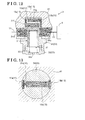
- Figs. 11 to 13 illustrate the hydraulic control device according to a third embodiment with the oil passage 15 for the communicative connection formed on the main body 34 of the valve body 33.
- Fig. 11 shows the flow passage area regulation unit 3 in the closed state and
- Fig. 12 shows the flow passage area regulation unit 3 in the state immediately before the open state.
- Fig. 13 is a cross-sectional view taken along XIII-XIII in Fig. 11 .
- the fundamental configuration of the spool 31 is similar to that of the second embodiment, thus duplicate descriptions are omitted.
- the main body 34 of the valve body 33 is formed with a first elongated groove 15a that connects to the upstream side of the openings 34a for the flow passage and a second elongated groove 15b that connects to the downstream side of the openings 34a for the flow passage.
- the first elongated groove 15a may be formed integrally with the supply passage 34c that supplies oil to the initiation space 38, as shown in Fig. 11 , or formed separately.
- the first elongated groove 15a and the second elongated groove 15b are in a communicative connection via a large diameter through-hole 15c, which serves as a through-hole, and a small diameter through-hole 15d.
- the oil passage 15 for the communicative connection which serves as the bypass channel, includes the first elongated groove 15a, the small diameter through-hole 15d, the large diameter through-hole 15c, and the second elongated groove 15b.
- the small diameter through-hole 15d includes a portion that serves as a regulator portion.
- the amount of oil that flows through the oil passage 15 for the communicative connection in the closed state may be easily controlled to the predetermined amount with the small diameter through-hole 15d having a predetermined dimension with an accuracy within the tolerance, even when the first elongated groove 15a, the second elongated groove 15b, and the large diameter through-hole 15c are processed with less accuracy.
- the small diameter through-hole 15d limits the amount of oil that flows through the oil passage 15 for the communicative connection to the predetermined amount, so that remaining oil may be used to apply the oil pressure to the surface 31f on the spool 31 subjected to the pressure.
- the oil pressure setting in which the spool 31 starts moving may be easily controlled with the dimension of the small diameter through-hole 15d.
- each of the first elongated groove 15a, the second elongated groove 15b, the large diameter through-hole 15c and the small diameter through-hole 15d may be provided with a straight form with a simple drill processing or a like method, which is advantageous in making the manufacturing process easy.
- the spool 31 is defined with the first range R, the range in which the dimension of the flow passage area of the oil passage 13 for the lubricating oil remains unchanged even if the spool 31 in the closed state as shown in Fig. 11 moves in the opening direction until the spool 31 reaches beyond the state immediately before the open state as shown in Fig. 12 .
- the dimension of the flow passage area of the oil passage 13 for the lubricating oil remains unchanged when the frictional force generated between the outer peripheral surfaces of the spool 31 and the inner peripheral surface of the valve body 33 changes from static to dynamic immediately after the spool 31 starts moving and makes the spool 31 move rapidly in the opening direction. Due to the above characteristic, a stable oil pressure may be applied to the valve timing control device 2 connected to the upstream side of the oil passage 13 for the lubricating oil.
- the portion serving as the first predetermined portion is described as a valve timing control device adapted for controlling the intake valves, however, the portion serving as the first predetermined portion is not limited to the valve timing control device adapted for controlling the intake valves.
- the portion serving as the first predetermined portion may be a valve timing control device adapted for controlling the exhaust valves, a supercharger that works under an appropriate oil pressure, or an oil jet and the like device that operates using oil pressure.
- the oil passage 15 for the communicative connection which serves as the bypass channel
- the configuration of the oil passage 15 for the communicative connection is not limited to the aforementioned configuration.
- a clearance may be defined between the valve body 33 and the valve housing 41, so that the clearance may serve as the bypass channel 15.
Applications Claiming Priority (1)
| Application Number | Priority Date | Filing Date | Title |
|---|---|---|---|
| JP2011090217A JP5783407B2 (ja) | 2011-04-14 | 2011-04-14 | 油圧制御装置 |
Publications (2)
| Publication Number | Publication Date |
|---|---|
| EP2511535A2 true EP2511535A2 (fr) | 2012-10-17 |
| EP2511535A3 EP2511535A3 (fr) | 2013-09-18 |
Family
ID=46022058
Family Applications (1)
| Application Number | Title | Priority Date | Filing Date |
|---|---|---|---|
| EP20120163591 Withdrawn EP2511535A3 (fr) | 2011-04-14 | 2012-04-10 | Dispositif de commande hydraulique |
Country Status (4)
| Country | Link |
|---|---|
| US (1) | US9291283B2 (fr) |
| EP (1) | EP2511535A3 (fr) |
| JP (1) | JP5783407B2 (fr) |
| CN (1) | CN202926421U (fr) |
Families Citing this family (7)
| Publication number | Priority date | Publication date | Assignee | Title |
|---|---|---|---|---|
| WO2012032813A1 (fr) | 2010-09-06 | 2012-03-15 | アイシン精機株式会社 | Dispositif de commande de pression d'huile |
| JP6007746B2 (ja) | 2012-11-20 | 2016-10-12 | アイシン精機株式会社 | 作動油供給装置 |
| JP6030585B2 (ja) * | 2014-01-17 | 2016-11-24 | トヨタ自動車株式会社 | オイルジェットバルブの取付方法 |
| JP6411228B2 (ja) * | 2015-01-19 | 2018-10-24 | アイシン・エィ・ダブリュ株式会社 | 伝達装置 |
| US10247066B2 (en) | 2015-08-11 | 2019-04-02 | Yamada Manufacturing Co., Ltd. | Relief valve device |
| US20200200264A1 (en) * | 2018-12-19 | 2020-06-25 | GM Global Technology Operations LLC | Split oil circuit |
| JP7363194B2 (ja) | 2019-08-27 | 2023-10-18 | 三菱自動車工業株式会社 | エンジンの潤滑装置 |
Citations (1)
| Publication number | Priority date | Publication date | Assignee | Title |
|---|---|---|---|---|
| JP2009299573A (ja) | 2008-06-12 | 2009-12-24 | Aisin Seiki Co Ltd | 車両用オイル供給装置 |
Family Cites Families (10)
| Publication number | Priority date | Publication date | Assignee | Title |
|---|---|---|---|---|
| JPS57173513A (en) * | 1981-04-17 | 1982-10-25 | Nippon Soken Inc | Variable valve engine |
| FR2626956B1 (fr) * | 1988-02-09 | 1990-05-04 | Legris Sa | Raccord-demarreur pour la mise en pression progressive des installations pneumatiques |
| JPH0763026A (ja) * | 1993-08-20 | 1995-03-07 | Nissan Motor Co Ltd | エンジンの潤滑油供給装置 |
| JPH10141036A (ja) * | 1996-09-13 | 1998-05-26 | Nippon Soken Inc | 内燃機関の潤滑油圧回路 |
| DE19923345A1 (de) * | 1999-05-21 | 2000-11-23 | Mannesmann Rexroth Ag | Elektrohydraulische Steuereinrichtung |
| JP2001336410A (ja) * | 2000-05-24 | 2001-12-07 | Unisia Jecs Corp | 内燃機関の油圧回路 |
| DE502005003090D1 (de) * | 2004-02-05 | 2008-04-17 | Bosch Rexroth Ag | Messblendenanordnung für ein hydraulisches stromteil- und stromsummiergerät |
| JP5582342B2 (ja) | 2009-09-24 | 2014-09-03 | アイシン精機株式会社 | 車両用オイル供給装置 |
| JP2011080430A (ja) * | 2009-10-08 | 2011-04-21 | Hitachi Automotive Systems Ltd | 制御弁と該制御弁が用いられた可変容量形ポンプ、並びに内燃機関の油圧回路 |
| WO2012032813A1 (fr) * | 2010-09-06 | 2012-03-15 | アイシン精機株式会社 | Dispositif de commande de pression d'huile |
-
2011
- 2011-04-14 JP JP2011090217A patent/JP5783407B2/ja not_active Expired - Fee Related
-
2012
- 2012-04-10 EP EP20120163591 patent/EP2511535A3/fr not_active Withdrawn
- 2012-04-12 US US13/445,619 patent/US9291283B2/en active Active
- 2012-04-16 CN CN2012201613339U patent/CN202926421U/zh not_active Expired - Fee Related
Patent Citations (1)
| Publication number | Priority date | Publication date | Assignee | Title |
|---|---|---|---|---|
| JP2009299573A (ja) | 2008-06-12 | 2009-12-24 | Aisin Seiki Co Ltd | 車両用オイル供給装置 |
Also Published As
| Publication number | Publication date |
|---|---|
| US20120261009A1 (en) | 2012-10-18 |
| JP5783407B2 (ja) | 2015-09-24 |
| US9291283B2 (en) | 2016-03-22 |
| CN202926421U (zh) | 2013-05-08 |
| JP2012219807A (ja) | 2012-11-12 |
| EP2511535A3 (fr) | 2013-09-18 |
Similar Documents
| Publication | Publication Date | Title |
|---|---|---|
| JP5270525B2 (ja) | 制御弁装置 | |
| US9291283B2 (en) | Hydraulic control device | |
| US8156906B2 (en) | Valve timing controller | |
| JP5471675B2 (ja) | オイル圧制御装置 | |
| US9133734B2 (en) | Valve timing control apparatus for internal combustion engine | |
| US6302072B1 (en) | Vane type hydraulic actuator | |
| EP2412944B1 (fr) | Contrôleur de temporisation d'ouverture/de fermeture de soupape | |
| JP4624976B2 (ja) | バルブタイミング調整装置 | |
| JP4459892B2 (ja) | バルブタイミング調整装置 | |
| US8640663B2 (en) | Oil pressure control apparatus | |
| JP5403341B2 (ja) | 弁開閉時期制御装置 | |
| US6263843B1 (en) | Valve timing control device of internal combustion engine | |
| JP2008175128A (ja) | バルブタイミング調整装置 | |
| JP2008069649A (ja) | バルブタイミング調整装置 | |
| US9464543B2 (en) | Valve opening/closing timing control device | |
| CN114761673A (zh) | 阀正时调整装置 | |
| US20060260577A1 (en) | Valve timing control apparatus and internal combustion engine | |
| US9157342B2 (en) | Valve timing control apparatus for internal combustion engine | |
| GB2530123A (en) | Variable valve timing control apparatus of internal combustion engine | |
| EP2708705A1 (fr) | Dispositif de réglage de distribution variable | |
| JP5780415B2 (ja) | 油圧制御装置 | |
| JP2012007543A (ja) | 油圧制御装置 | |
| JP4459893B2 (ja) | バルブタイミング調整装置 | |
| WO2020085057A1 (fr) | Dispositif de commande de réglage de distribution pour moteur à combustion interne |
Legal Events
| Date | Code | Title | Description |
|---|---|---|---|
| PUAI | Public reference made under article 153(3) epc to a published international application that has entered the european phase |
Free format text: ORIGINAL CODE: 0009012 |
|
| AK | Designated contracting states |
Kind code of ref document: A2 Designated state(s): AL AT BE BG CH CY CZ DE DK EE ES FI FR GB GR HR HU IE IS IT LI LT LU LV MC MK MT NL NO PL PT RO RS SE SI SK SM TR |
|
| AX | Request for extension of the european patent |
Extension state: BA ME |
|
| PUAL | Search report despatched |
Free format text: ORIGINAL CODE: 0009013 |
|
| AK | Designated contracting states |
Kind code of ref document: A3 Designated state(s): AL AT BE BG CH CY CZ DE DK EE ES FI FR GB GR HR HU IE IS IT LI LT LU LV MC MK MT NL NO PL PT RO RS SE SI SK SM TR |
|
| AX | Request for extension of the european patent |
Extension state: BA ME |
|
| RIC1 | Information provided on ipc code assigned before grant |
Ipc: F01L 1/344 20060101ALI20130809BHEP Ipc: F15B 13/02 20060101ALI20130809BHEP Ipc: F15B 11/16 20060101ALI20130809BHEP Ipc: F15B 13/04 20060101AFI20130809BHEP |
|
| 17P | Request for examination filed |
Effective date: 20140124 |
|
| RBV | Designated contracting states (corrected) |
Designated state(s): AL AT BE BG CH CY CZ DE DK EE ES FI FR GB GR HR HU IE IS IT LI LT LU LV MC MK MT NL NO PL PT RO RS SE SI SK SM TR |
|
| 17Q | First examination report despatched |
Effective date: 20140728 |
|
| STAA | Information on the status of an ep patent application or granted ep patent |
Free format text: STATUS: THE APPLICATION IS DEEMED TO BE WITHDRAWN |
|
| 18D | Application deemed to be withdrawn |
Effective date: 20141210 |