EP2510984A1 - Fremdenergieunabhängiger Melder - Google Patents
Fremdenergieunabhängiger Melder Download PDFInfo
- Publication number
- EP2510984A1 EP2510984A1 EP12154264A EP12154264A EP2510984A1 EP 2510984 A1 EP2510984 A1 EP 2510984A1 EP 12154264 A EP12154264 A EP 12154264A EP 12154264 A EP12154264 A EP 12154264A EP 2510984 A1 EP2510984 A1 EP 2510984A1
- Authority
- EP
- European Patent Office
- Prior art keywords
- detector
- thermal tripping
- piezoelectric element
- signal
- coupling element
- Prior art date
- Legal status (The legal status is an assumption and is not a legal conclusion. Google has not performed a legal analysis and makes no representation as to the accuracy of the status listed.)
- Granted
Links
Images



Classifications
-
- A—HUMAN NECESSITIES
- A62—LIFE-SAVING; FIRE-FIGHTING
- A62C—FIRE-FIGHTING
- A62C37/00—Control of fire-fighting equipment
- A62C37/36—Control of fire-fighting equipment an actuating signal being generated by a sensor separate from an outlet device
-
- A—HUMAN NECESSITIES
- A62—LIFE-SAVING; FIRE-FIGHTING
- A62C—FIRE-FIGHTING
- A62C37/00—Control of fire-fighting equipment
- A62C37/08—Control of fire-fighting equipment comprising an outlet device containing a sensor, or itself being the sensor, i.e. self-contained sprinklers
- A62C37/10—Releasing means, e.g. electrically released
- A62C37/11—Releasing means, e.g. electrically released heat-sensitive
-
- F—MECHANICAL ENGINEERING; LIGHTING; HEATING; WEAPONS; BLASTING
- F16—ENGINEERING ELEMENTS AND UNITS; GENERAL MEASURES FOR PRODUCING AND MAINTAINING EFFECTIVE FUNCTIONING OF MACHINES OR INSTALLATIONS; THERMAL INSULATION IN GENERAL
- F16K—VALVES; TAPS; COCKS; ACTUATING-FLOATS; DEVICES FOR VENTING OR AERATING
- F16K11/00—Multiple-way valves, e.g. mixing valves; Pipe fittings incorporating such valves
- F16K11/02—Multiple-way valves, e.g. mixing valves; Pipe fittings incorporating such valves with all movable sealing faces moving as one unit
- F16K11/06—Multiple-way valves, e.g. mixing valves; Pipe fittings incorporating such valves with all movable sealing faces moving as one unit comprising only sliding valves, i.e. sliding closure elements
- F16K11/065—Multiple-way valves, e.g. mixing valves; Pipe fittings incorporating such valves with all movable sealing faces moving as one unit comprising only sliding valves, i.e. sliding closure elements with linearly sliding closure members
- F16K11/07—Multiple-way valves, e.g. mixing valves; Pipe fittings incorporating such valves with all movable sealing faces moving as one unit comprising only sliding valves, i.e. sliding closure elements with linearly sliding closure members with cylindrical slides
-
- F—MECHANICAL ENGINEERING; LIGHTING; HEATING; WEAPONS; BLASTING
- F16—ENGINEERING ELEMENTS AND UNITS; GENERAL MEASURES FOR PRODUCING AND MAINTAINING EFFECTIVE FUNCTIONING OF MACHINES OR INSTALLATIONS; THERMAL INSULATION IN GENERAL
- F16K—VALVES; TAPS; COCKS; ACTUATING-FLOATS; DEVICES FOR VENTING OR AERATING
- F16K17/00—Safety valves; Equalising valves, e.g. pressure relief valves
- F16K17/36—Safety valves; Equalising valves, e.g. pressure relief valves actuated in consequence of extraneous circumstances, e.g. shock, change of position
- F16K17/38—Safety valves; Equalising valves, e.g. pressure relief valves actuated in consequence of extraneous circumstances, e.g. shock, change of position of excessive temperature
-
- F—MECHANICAL ENGINEERING; LIGHTING; HEATING; WEAPONS; BLASTING
- F16—ENGINEERING ELEMENTS AND UNITS; GENERAL MEASURES FOR PRODUCING AND MAINTAINING EFFECTIVE FUNCTIONING OF MACHINES OR INSTALLATIONS; THERMAL INSULATION IN GENERAL
- F16K—VALVES; TAPS; COCKS; ACTUATING-FLOATS; DEVICES FOR VENTING OR AERATING
- F16K31/00—Actuating devices; Operating means; Releasing devices
- F16K31/004—Actuating devices; Operating means; Releasing devices actuated by piezoelectric means
-
- F—MECHANICAL ENGINEERING; LIGHTING; HEATING; WEAPONS; BLASTING
- F16—ENGINEERING ELEMENTS AND UNITS; GENERAL MEASURES FOR PRODUCING AND MAINTAINING EFFECTIVE FUNCTIONING OF MACHINES OR INSTALLATIONS; THERMAL INSULATION IN GENERAL
- F16K—VALVES; TAPS; COCKS; ACTUATING-FLOATS; DEVICES FOR VENTING OR AERATING
- F16K31/00—Actuating devices; Operating means; Releasing devices
- F16K31/02—Actuating devices; Operating means; Releasing devices electric; magnetic
- F16K31/06—Actuating devices; Operating means; Releasing devices electric; magnetic using a magnet, e.g. diaphragm valves, cutting off by means of a liquid
- F16K31/08—Actuating devices; Operating means; Releasing devices electric; magnetic using a magnet, e.g. diaphragm valves, cutting off by means of a liquid using a permanent magnet
- F16K31/084—Actuating devices; Operating means; Releasing devices electric; magnetic using a magnet, e.g. diaphragm valves, cutting off by means of a liquid using a permanent magnet the magnet being used only as a holding element to maintain the valve in a specific position, e.g. check valves
-
- A—HUMAN NECESSITIES
- A62—LIFE-SAVING; FIRE-FIGHTING
- A62C—FIRE-FIGHTING
- A62C37/00—Control of fire-fighting equipment
- A62C37/36—Control of fire-fighting equipment an actuating signal being generated by a sensor separate from an outlet device
- A62C37/38—Control of fire-fighting equipment an actuating signal being generated by a sensor separate from an outlet device by both sensor and actuator, e.g. valve, being in the danger zone
- A62C37/40—Control of fire-fighting equipment an actuating signal being generated by a sensor separate from an outlet device by both sensor and actuator, e.g. valve, being in the danger zone with electric connection between sensor and actuator
Definitions
- the invention relates to a foreign energy independent detector according to the preamble of the first claim.
- the detector can be used everywhere, where after a temperature change at a defined temperature for signaling, switching and / or control purposes, a signal is generated and no electrical energy through a battery, an accumulator or other power supply is present or not sure and is available on a regular basis.
- This can for example in extinguishing devices such as extinguishing systems or devices for extinguishing agent storage such.
- a fire extinguisher to be triggered by an energy-independent release device, or in other autonomous systems for monitoring the case.
- a fire-endangered area can be monitored independently of the external energy, without battery, without accumulator or other power supply, and when a defined temperature is exceeded, a generated voltage or current signal can be used to signal or control follow-up actions.
- this overload overloads can be realized that respond when the set temperature is exceeded and, for. cause the shutdown of a device or settle a fault signal.
- self-sufficient units that have to work as long as possible in vehicles of all kinds, in space etc.
- DE 199 45 856 B4 describes a sprinkler device with a valve which opens according to predetermined criteria, this valve being controlled by a sensor which responds quickly to parameters arising during a fire, several sensors being provided which control the valve by means of an evaluation algorithm and the sensors can respond to different parameters of the fire.
- the document describes a glass tube on which a piezoelectric behavior is used to trigger an alarm. The power supply takes place by means of electrical line and battery.
- US 2009/0301601 A1 uses a piezo igniter, which generates a spark voltage by triggering a push button as known from any lighter, with the help of a combustion process is started, the exhaust gases are used for other processes.
- US 2007/0215362 A1 describes a fire extinguishing system in which a cover plate with a fusible link is arranged on a fire extinguisher, by means of a piezoelectric switch an alarm triggering is possible. Once a certain temperature is exceeded, the fusible link melts and the cover plate of the sprinkler housing drops down, with a switch triggering an alarm.
- a piezoelectric switch which is in reality a piezoelectric sounder.
- US 2011/0278029 A1 describes a self-powered modular fire suppression unit that can be mounted on a ceiling.
- a circuit board On a circuit board is a piezo element, which is triggered by a smoke sensor and triggers an acoustic signal.
- a circuit board on a gas cap On a circuit board on a gas cap is a glass tube, which bursts in heat. The glass tube acts against a spring and a switch that triggers an alarm signal.
- For the power supply of the device batteries are provided.
- a disadvantage of this prior art is that the existing detectors that generate a signal due to a change in temperature for signaling, switching and / or control purposes, require energy storage via batteries or a power supply.
- the solution according to the invention provides a detector independent of external energy, which generates a signal for signaling, switching and / or control purposes due to temperature changes.
- This can be a signal for an alarm, a signal for a fire alarm and / or extinguishing control panel, for a triggering device such as a valve or other monitoring or safety device when a defined temperature is reached.
- the detector can advantageously also as Overload signal transmitter can be used, which signals the too high or too low temperature of a device, component or room and / or triggers a control or shutdown mechanism.
- the detector can be used wherever a signal is to be triggered at a defined temperature. This can be, for example, the occurrence of a fire event or the temperature increase in a device to be monitored, such as in control cabinets.
- the external energy independent detector for the protection of kitchen equipment such as fryers and other fat heating devices can be used. Also for securing and monitoring of thermal process processes, of furnaces, engines, vehicles, aircraft and ships and other mobile and stationary objects and this detector can be used.
- the detector according to the invention consists of at least one piezoelectric element, a thermal tripping element, a coupling element and a housing and / or frame, in which all these components are arranged functionally.
- the thermal tripping element is designed such that it is destroyed by thermal action or changes its structure. It can melt, shrink or soften. It can also change its state of aggregation or its spatial dimensions.
- the thermal tripping element consists of a material which changes in length due to temperature change in at least one spatial direction, i. expands or shortens. Another advantage is the use of memory metals. It is advantageous if the triggering element is a liquid-filled glass ampoule such as e.g. used in sprinklers, a fusible link is a plastic element or a metal rod or pyrotechnic element.
- the coupling element exerts a force on the piezoelectric element when the thermal tripping element changes state at a defined temperature.
- This coupling element can be realized for example by prestressed springs or other elastically deformed parts or by force-transmitting parts such as plungers.
- the arrangement of the thermal tripping element, the coupling element and the piezoelectric element in a housing / holder is chosen so that through the Change in state of the thermal tripping element at a defined temperature, the stored potential energy of the spring or the elastically deformed part is released and the resulting force exerts a mechanical pressure on the piezoelectric element and the piezoelectric effect, a voltage signal is generated.
- the generated voltage can be several 100V.
- the coupling element can also be an adhesive or air gap, so that the state change of the thermal release element, for example a pyrotechnic, is transmitted directly to the piezoelectric element and exerts a force and a mechanical pressure on it
- piezoelectric element any material can be used which produces a piezoelectric effect, for example piezoelectric crystals such as quartz, lithium niobate, gallium orthophosphate or piezoelectric ceramics such as lead zirconate titanates or lead magnesium niobates or thin layers of zinc oxide or aluminum nitride or plastics such as polyvinylidene fluoride.
- the voltage generated by the piezoelectric element can be used at terminals or cables at the detector for signal processing or signal provision.
- Parts of the detector such as the frame can be designed as live parts in order to reduce the number of cable connections.
- a charge amplification of the charges generated on the piezoelectric element and / or further signal processing such. B. take the impedance matching to the further signal use.
- the electrical voltages / currents from the piezoelectric element are dissipated via electrically conductive components of the detector or cable and can be evaluated inside and / or outside the detector, for example by means of an electronic circuit provided for this purpose.
- the voltage signal / current signal generated in the detector is conducted directly via cable to an electrically controllable element.
- an electrically controllable element This can be a solenoid valve or an electrically deactivatable Elektropermanentmagnet. But also bistable relay or surge switch for switching larger electrical loads are also conceivable:
- the generated voltage signal other trigger components consisting of pyrotechnic or explosive materials control or ignite.
- the voltage generated at the piezoelectric element is conducted via a cable to an electro-permanent magnet, whereby the adhesive force of the magnet is released and the double piston is moved by the spring force, whereby a valve is opened.
- the Elektropermanentmagnet consists of a permanent magnet with a coil which serves in current flow for demagnetization of the permanent magnet, so is an electrically demagnetizable permanent magnet.
- the detector sends an electrical signal to a fire alarm and / or extinguishing control center.
- another evaluation device such as a control device for another device.
- the detector according to the invention has the advantage that it requires no external energy in the form of batteries, accumulators or an external power supply, creating a reliable, effectively over very long periods, inexpensive and less expensive material triggering device for switching and control purposes arises.
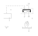
- FIG. 1 shows the external energy independent detector 3 at the triggering device of an extinguishing device.
- the detector 3 consisting of a piezo element 3.1, the thermal release element 3.2 and the coupling element 11 and the holder or housing 3.3.
- the thermal tripping element 3.2 represents a sprinkler ampoule or a fusible link. Upon reaching a defined temperature, there is a change in state of the thermal tripping element 3.2, it bursts the sprinkler ampoule or melts the fusible link.
- the arrangement of the thermal tripping element 3.2, the coupling element 11 and the piezoelectric element 3.1 in the housing / holder 3.3 is designed so that by the change in state of the thermal tripping element 3.2 at a defined temperature on the coupling element 11, a force or a mechanical pressure on a piezoelectric element 3.1 is exercised and via the piezo effect, a voltage signal is generated.
- the detector 3 is positioned above the protected object 6 in order to enable a signaling, control or switching operation at a defined temperature, for example in the temperature range 70 to 300 degrees Celsius. In the present example, the temperature range is in the area where a fire occurs.
- the cable 4 connects the terminals 14 of the piezoelectric element 3.1 and the detector 3 to the terminals of the electrically triggered valve 2.
- the valve 2 closes the opening of the extinguishing agent container 1, in which the propellant 1.2 and the extinguishing 1.3 are.
- the riser 1.1 is used to discharge the extinguishing agent 1.3 via the valve 2 to the extinguishing nozzle 5 on the object to be protected 6.
- the activation of the triggering device, the valve 2 takes place in case of fire on the thermal tripping element 3.2.
- the voltage signal thus generated is via the cable 4 for Electro-permanent magnet 2.9 is passed.
- the briefly applied voltage is sufficient to cancel the magnetic field of the permanent magnet 2.9 or its adhesive force.
- the double piston 2.3 is released and moved by the spring force of the compression spring 2.4 in the open valve position. That under permanent pressure of a Propellant 1.2 standing extinguishing agent 1.3 is conveyed via a riser 1.1 to the extinguishing nozzles 5, whereby the fire is extinguished at the object 6.
- the double piston 2.3 adheres to the permanent magnet 2.9 by means of the steel disc 2.8.
- the compression spring 2.4 is in the cocked position, the spring force is less than the adhesive force of the permanent magnet 2.9.
- the extinguishant pressure acts on two identically dimensioned pistons 2.3.1. The pressure forces on both pistons 2.3.1 cancel each other out. There is no net pressure on the piston.
- the extinguishing agent 1.3 is in the pressure chamber 2.15 in the resting state.
- the electropermanent holding magnet 2.9 Upon activation of the triggering device, the electropermanent holding magnet 2.9 is acted upon by a voltage pulse coming from the piezoelement 3.1. As a result, the adhesive force of the permanent magnet 2.9 is temporarily removed and released the force of the compression spring 2.4. The compression spring 2.4 moves the double piston 2.3 in the open position and the extinguishing 1.3 can be passed to the nozzles 5 to the double piston 2.3 from the extinguishing agent outlet nozzle 2.11.
- FIG. 2 shows a system with an evaluation device 7, in this case with a fire alarm and control center that receives the signal of the detector 3 in case of fire and / or initiates the deletion process.
- FIG. 3 is the schematic representation of a separate external energy detector with a sprinkler ampoule or fusible link as a thermal tripping element 3.2.
- a sprinkler ampoule or fusible link as a thermal tripping element 3.2.
- the coupling element 11 which consists of the spring 9 and the plunger 8
- a force or a mechanical pressure exerted on the piezoelectric element 3.1 wherein at the terminals 14, a voltage signal for signaling, - switching or control purposes can be tapped.
- Via the circuit 12 there is a charge amplification of the charges generated at the piezoelectric element 3.1 and / or the further signal processing such.
- FIG. 4 represents a external energy independent detector 3 with a pyrotechnic element as a thermal tripping element 3.2.
- the pyrotechnic triggering element 3.2 is arranged in a gas expansion space 13.
- a pressure surge which acts on the coupling element 11 in the form of a plunger.
- Via the coupling element 11, a force or a mechanical pressure is exerted on the piezoelectric element 3.1, wherein at the terminals 14, a voltage signal for signaling, - switching or control purposes can be tapped.
- Via the circuit 12 there is a charge amplification of the charges generated on the piezoelectric element 3.1 and / or further signal processing such as, for example, the impedance matching to the further signal use.
- FIG. 5 represents a external energy independent detector with a pyrotechnic element or a memory metal element as a thermal tripping element 3.2.
- This tripping element is attached directly to the piezoelectric element 3.1.
- Upon reaching a defined temperature ignites the pyrotechnic element or expands the memory metal element and generates a force or a mechanical pressure directly on the piezoelectric element 3.1 and the terminals 14, a voltage signal for signaling, - switching or control purposes can be tapped.
- the coupling element 11 is reduced in this case to a contact surface or mounting surface or air gap between the thermal tripping element 3.2 and the piezoelectric element 3.1.
- a charge amplification of the charges generated at the piezoelectric element 3.1 and / or further signal processing such as the impedance matching to the further signal use instead.
- FIGS. 3 to 5 show that the arrangement of the thermal tripping element 3.2, the coupling element 11 and the piezoelectric element 3.1 in the housing / holder 3.3 is designed so that by the change in state of the thermal tripping element 3.1 at a defined temperature on the coupling element 11, a force or a mechanical pressure the piezo element 3.1 is exerted.
Landscapes
- Engineering & Computer Science (AREA)
- General Engineering & Computer Science (AREA)
- Mechanical Engineering (AREA)
- Health & Medical Sciences (AREA)
- Public Health (AREA)
- Business, Economics & Management (AREA)
- Emergency Management (AREA)
- Fire-Extinguishing By Fire Departments, And Fire-Extinguishing Equipment And Control Thereof (AREA)
- Safety Valves (AREA)
- Magnetically Actuated Valves (AREA)
Abstract
bestehend aus einem thermischen Auslöeseelement (3.2), mindestens einem Piezoelement (3.1) und einem Koppelelement (11) die so in einer Halterung/Gehäuse (3.3) so angeordnet sind, dass durch eine Zustandsänderung der thermischen Auslöseelemente (3.2) bei einer definierten Temperatur oder einem Temperaturbereich über das Koppelelement (11) ein mechanischer Druck auf das Piezoelement (3.2) ausgeübt wird, so dass ein elektrisches Signal entsteht.
Description
- Die Erfindung betrifft einen fremdenergieunabhängigen Melder nach dem Oberbegriff des ersten Patentanspruches.
- Der Melder ist überall dort einsetzbar, wo nach einer Temperaturänderung bei einer definierten Temperatur für Signalisierungs-, Schalt- und/oder Steuerzwecke ein Signal zu erzeugen ist und keine elektrische Energie durch eine Batterie, einen Akkumulator oder eine andere Stromversorgung vorhanden ist oder diese nicht sicher und regelmäßig zur Verfügung steht. Das kann beispielsweise bei Löschvorrichtungen wie Löschanlagen oder Vorrichtungen zur Löschmittelbevorratung wie z. B. einem Feuerlöscher, der durch eine energieunabhängige Auslöseeinrichtung ausgelöst werden soll, oder bei anderen autonomen Systemen zur Überwachung der Fall sein. So kann ein brandgefährdeter Bereich fremdenergieunabhängig, ohne Batterie, ohne Akkumulator oder andere Stromversorgung überwacht werden und bei überschreiten einer definierten Temperatur ein erzeugtes Spannungs- oder Stromsignal zur Signalisierung oder Steuerung von Folgeaktionen genutzt werden. Weiterhin lassen sich hiermit Überlastsicherungen realisieren, die bei Überschreiten der Solltemperatur ansprechen und z.B. die Abschaltung eines Gerätes bewirken oder ein Störungssignal absetzen. Speziell in autarken Einheiten die möglichst lange funktionieren müssen wie in Fahrzeugen aller Art, im Weltraum etc.
-
DE 199 45 856 B4 beschreibt eine Sprinklervorrichtung mit einem Ventil, das bei vorgegebenen Kriterien öffnet, wobei dieses Ventil durch einen Sensor angesteuert wird, der schnell auf Parameter anspricht, die bei einem Feuer entstehen, wobei mehrere Sensoren vorgesehen sind, die mittels eines Auswertealgorithmus das Ventil ansteuern und die Sensoren auf verschiedene Parameter des Feuers ansprechen können. In einer besonderen Ausführungsvariante beschreibt das Dokument ein Glasröhrchen, an dem ein piezoelektrisches Verhalten zum Auslösen eines Alarms genutzt wird. Die Stromversorgung erfolgt mittels elektrischer Leitung und Batterie. -
US 2009/0301601 A1 verwendet einen Piezo-Zünder, welcher durch Auslösen eines Druckknopfes eine Funkenspannung erzeugt wie aus jedem Feuerzeug bekannt, mit dessen Hilfe ein Verbrennungsprozess gestartet wird, dessen Abgase für weitere Prozesse genutzt werden. -
US 2007/0215362 A1 beschreibt ein Feuerlöschsystem, bei dem an einer Feuerlöschdüse eine Abdeckplatte mit einem Schmelzlot angeordnet ist, mittels eines piezoelektrischen Schalters ist ein Alarmauslösen möglich. Sobald eine bestimmte Temperatur überschritten ist, schmilzt das Schmelzlot und die Abdeckplatte des Sprinklergehäuses fällt herunter, wobei ein Schalter Alarm auslöst. In diesem Dokument wird ein als piezoelektrischer Schalter bezeichnetes Gerät erwähnt, bei dem es sich in Wirklichkeit um einen piezoelektrischen akustischen Signalgeber handelt. -
US 2011/0278029 A1 beschreibt eine eigenständige selbstauslösende modulare Feuerunterdrückungseinheit, die an einer Decke montiert sein kann. Auf einer Leiterplatte befindet sich ein Piezo-Element, welches durch einen Rauchsensor ausgelöst wird und ein akustisches Signal auslöst. Auf einer Leiterplatte auf einem Tankdeckel befindet sich ein Glasröhrchen, welches bei Hitze birst. Das Glasröhrchen wirkt gegen eine Feder und einen Schalter, der ein Alarmsignal auslöst. Für die Energieversorgung der Vorrichtung sind Batterien vorgesehen. - Nachteilig an diesem Stand der Technik ist, daß die bestehenden Melder, die ein Signal auf Grund einer Temperaturänderung für Signalisierungs-, Schalt- und/oder Steuerzwecke erzeugen, eine Energiebevorratung über Batterien oder eine Spannungsversorgung benötigen.
- Es ist daher Aufgabe der Erfindung, einen Melder, der keine Batterie, keinen Akkumulator und keine externe Stromversorgung benötigt, zu entwickeln, dessen Auslösen auf Grund von Temperaturänderungen einfach und unabhängig von einer Energieversorgung erfolgt.
- Diese Aufgabe wird durch einen fremdenergieunabhängigen Melder für Signalsierungs-, Schalt- und Steuerzwecke nach den Merkmalen des ersten Patentanspruches gelöst.
- Unteransprüche geben vorteilhafte Ausgestaltungen der Erfindung wieder.
- Die erfindungsgemäße Lösung sieht einen fremdenergieunabhängigen Melder vor, der ein Signal für Signalisierungs-, Schalt- und/oder Steuerzwecke auf Grund von Temperaturänderungen erzeugt. Das kann ein Signal für einen Alarm, ein Signal für eine Brandmelder- und/oder Löschsteuerzentrale, für eine Auslöseeinnrichtung wie ein Ventil oder eine andere Überwachungs- oder Sicherheitseinrichtung sein, wenn eine definierte Temperatur erreicht wird. Der Melder kann vorteilhafterweise auch als Überlastsignalgeber verwendet werden, der die zu hohe oder zu niedrige Temperatur eines Gerätes, Bauteils oder Raumes signalisiert und/oder einen Steuer- oder Abschaltmechanismus auslöst.
- Der Melder kann überall dort eingesetzt werden, wo bei einer definierten Temperatur ein Signal ausgelöst werden soll. Das kann zum Beispiel das Auftreten eines Brandereignisses sein oder die Temperaturerhöhung in einer zu überwachenden Einrichtung wie zum Beispiel in Schaltschränken.
- So kann in einer beispielhaften Anwendung der fremdenergieunabhängige Melder zum Schutz von Kücheneinrichtungen wie z.B. Friteusen und anderen fettaufheizenden Geräten eingesetzt werden.
Auch zur Sicherung und Überwachung von thermischen Verfahrensprozessen, von Öfen, Motoren, Fahrzeugen, Flugzeugen und Schiffen und anderen mobilen und stationären Objekten und ist dieser Melder einsetzbar. - Der erfindungsgemäße Melder besteht aus mindestens einem Piezoelement, einem thermischen Auslöselement, einem Koppelelement und einem Gehäuse und/oder Rahmen, in dem alle diese Komponenten funktional angeordnet sind.
- Das thermische Auslöseelement ist so beschaffen, dass es durch thermische Einwirkung zerstört wird oder seine Struktur ändert. Es kann schmelzen, schrumpfen oder weich werden. Es kann auch seinen Aggregatzustand oder seine räumlichen Abmaße ändern. In diesem Fall besteht das thermische Auslöseelement aus einem Material, welches sich durch Temperaturänderung in mindestens einer Raumrichtung in seiner Länge ändert, d.h. sich ausdehnt oder verkürzt. Vorteilhaft ist auch der Einsatz von Memorymetallen. Vorteilhaft ist es, wenn das Auslöseelement eine flüssigkeitsgefüllte Glasampulle wie sie z.B. in Sprinklern verwendet wird, ein Schmelzlot ein Kunststoffelement oder ein Metallstab oder ein pyrotechnisches Element darstellt.
- Das Koppelelement übt eine Kraft auf das Piezoelement aus, wenn bei einer definierten Temperatur das thermische Auslöselement seinen Zustand ändert. Dieses Koppelelement kann z.B. durch vorgespannte Federn oder andere elastisch verformte Teile bzw. durch Kraftübertragende Teile wie z.B. Stößel realisiert werden. Die Anordnung des thermischen Auslöseelementes, des Koppelelementes und des Piezoelements in einem Gehäuse/Halterung ist so gewählt, dass durch die Zustandsänderung des thermische Auslöselements bei einer definierten Temperatur die gespeicherte potentielle Energie der Feder oder des elastisch verformten Teiles freigegeben wird und die resultierende Kraft einen mechanischen Druck auf das Piezoelement ausübt und über den Piezoeffekt ein Spannungssignal wird erzeugt. Die erzeugte Spannung kann mehrere 100 V betragen. Es ist vorteilhaft mehrere mechanisch in Serie und elektrisch parallel geschaltete Piezoelemente zu verwenden. Das Koppelelement kann auch ein Kleber bzw. Luftspaltsein, so dass die Zustandsänderung des thermischen Auslöseelementes, z.B. ein pyrotechnisches, direkt auf das Piezoelement übertragen wird und auf dieses eine Kraft und einen mechanischen Druck ausübt
- Bei Verwendung von thermischen Auslöseelementen, die bei definierten Temperaturen eine Längen- oder Volumenzunahme bzw. Aggregatszustandsänderung aufweisen, bewirkt diese Zustandsänderung des thermischen Auslöseelementes eine Kraftwirkung direkt über das Koppelelement zur Erzeugung des mechanischen Drucks auf das Piezoelement oder indirekt über die Freisetzung der im Koppelelement gespeicherte potentielle Energie.
Als Piezoelement kann jedes Material verwendet werden, welches einen Piezoeffekt erzeugt, z.B. piezoelektrische Kristalle wie Quarz, Lithiumniobat, Galliumorthophosphat oder piezoelektrische Keramiken wie Blei-Zirkonat-Titanate oder Blei-Magnesium-Niobate oder dünne Schichten aus Zinkoxid oder Aluminiumnitrid bzw. Kunststoffe wie Polyvinylidenfluorid . - Die vom Piezoelement erzeugte Spannung kann an Anschlüssen oder Kabeln am Melder zur Signalverarbeitung oder Signalbereitstellung verwendet werden Teile des Melders wie der Rahmen können als spannungsführende Teile ausgebildet sein, um die Zahl der Kabelverbindungen zu verringern.
Optional kann über eine zusätzliche elektrische Schaltung eine Ladungsverstärkung der am Piezoelement erzeugten Ladungen und/oder weitere Signalaufbereitungen wie z. B. die Impedanzanpassung an die weitere Signalverwendung stattfinden. - Die elektrischen Spannungen/Ströme aus dem Piezoelement werden über elektrisch leitfähige Komponenten des Melders oder Kabel abgeführt und können innerhalb und/oder außerhalb des Melders ausgewertet werden, z.B. mittels einer dafür vorgesehenen elektronischen Schaltung.
- In einer bevorzugten Ausführung wird das im Melder generierte Spannungssignal/Stromsignal direkt über Kabel an ein elektrisch steuerbares Element geleitet. Das kann ein Magnetventil sein oder ein elektrisch deaktivierbarer Elektropermanentmagnet. Denkbar sind aber auch bistabile Relais oder Stromstossschalter zur Schaltung größerer elektrischer Lasten: Weiterhin kann durch das erzeugte Spannungssignal andere Auslösekomponenten bestehend aus Pyrotechnischen- oder Sprengstoffmaterialien ansteuern bzw. zünden.
- In einer weiter bevorzugten Ausführung wird bei Erreichen einer definierten Temperatur durch das thermische Auslöseelement die erzeugte Spannung am Piezoelement über ein Kabel zu einem Elektropermanentmagneten geleitet, wodurch die Haftkraft des Magneten aufgehoben wird und der Doppelkolben durch die Federkraft bewegt wird, wodurch ein Ventil geöffnet wird. Der Elektropermanentmagnet besteht aus einem Permanentmagnet mit einer Spule die bei Stromdurchfluss zur Entmagnetisierung des Permanentmagnetes dient, ist also ein elektrisch entmagnetisierbarer Permanentmagnet.
- In einer weiteren bevorzugten Ausgestaltung sendet der Melder ein elektrisches Signal an eine Brandmelder- und/oder Löschsteuerzentrale. Denkbar ist aber auch eine andere Auswerteeinrichtung wie eine Steuereinrichtung für eine andere Vorrichtung.
- Der erfindungsgemäße Melder hat den Vorteil, dass er keine Fremdenergie in Form von Batterien, Akkumulatoren oder einen externe Stromversorgung benötigt, wodurch eine zuverlässige, über sehr lange Zeiträume wirksam bleibende, preiswerte und wenig materialaufwendige Auslöseeinrichtung für Schalt- und Steuerzwecke entsteht.
- Im Folgenden soll die Erfindung an Ausführungsbeispielen und fünf Figuren näher erläutert werden. Die Figuren zeigen:
- Figur 1:
- Schematische Darstellung des fremdenergieunabhängigen Melders mit direkter Wirkung auf die Auslöseeinrichtung einer Löschvorrichtung
- Figur 2:
- Schematische Darstellung des fremdenergieunabhängig wirkenden Melders mit Signalweitergabe an eine Brandmelder- und/oder Löschsteuerzentrale.
- Figur 3:
- Schematische Darstellung eines fremdenergieunabhängigen Melders mit einer Sprinklerampulle oder Schmelzlot als thermisches Auslöseelement.
- Figur 4:
- Schematische Darstellung eines fremdenergieunabhängigen Melders mit einem pyrotechnischen Element als thermisches Auslöseelement.
- Figur 5:
- Schematische Darstellung eines fremdenergieunabhängigen Melders mit direkter Wirkung eines thermischen Auslöseelement.
-
Figur 1 zeigt den fremdenergieunabhängigen Melder 3 an der Auslöseeinrichtung einer Löschvorrichtung. Der Melder 3, bestehend aus einem Piezoelement 3.1, dem thermischen Auslöselement 3.2 und dem Koppelelement 11 sowie der Halterung oder Gehäuse 3.3. Das thermische Auslöselement 3.2 stellt eine Sprinklerampulle oder ein Schmelzlot dar. Bei erreichen einer definierten Temperatur kommt es zu einer Zustandsänderung des thermischen Auslöseelementes 3.2, es birst die Sprinklerampulle oder schmilzt das Schmelzlot.
Die Anordnung des thermischen Auslöseelementes 3.2, des Koppelelementes 11 und des Piezoelements 3.1 im Gehäuse/Halterung 3.3 ist so ausgelegt, dass durch die Zustandsänderung des thermischen Auslöseelements 3.2 bei einer definierten Temperatur über das Koppelelement 11 eine Kraft bzw. ein mechanischer Druck auf das eine Piezoelement 3.1 ausgeübt wird und über den Piezoeffekt ein Spannungssignal erzeugt wird. - Der Melder 3 wird über dem Schutzobjekt 6 positioniert, um bei einer definierten Temperatur, z.B. im Temperaturbereich 70 bis 300 Grad Celsius einen Signalisierungs-, Steuer- oder Schaltvorgang zu ermöglichen. Im vorliegenden Beispiel liegt der Temperaturbereich in dem Bereich, in dem ein Brand entsteht.
Das Kabel 4 verbindet die Anschlüsse 14 des Piezoelementes 3.1 bzw. des Melders 3 mit den Anschlüssen des elektrisch auslösbaren Ventils 2. Das Ventil 2 verschließt die Öffnung des Löschmittelbehälters 1, in dem sich das Treibgas 1.2 und des Löschmittel 1.3 befinden. Das Steigrohr 1.1 dient zum austragen des Löschmittels 1.3 über das Ventil 2 zu der Löschdüse 5 über dem Schutzobjekt 6. Die Aktivierung der Auslöseeinrichtung, dem Ventil 2, erfolgt im Brandfall über das thermische Auslöseelement 3.2.
Das so erzeugte Spannungssignal wird über das Kabel 4 zum
Elektropermanentmagneten 2.9 geleitet wird. Die kurzzeitig anliegende Spannung genügt, um das Magnetfeld des Permanentmagneten 2.9 bzw. seine Haftkraft aufzuheben. Der Doppelkolben 2.3 wird freigegeben und durch die Federkraft der Druckfeder 2.4 in die geöffnete Ventilstellung bewegt. Das unter Permanentdruck eines Treibgases 1.2 stehende Löschmittel 1.3 wird über ein Steigrohr 1.1 zu den Löschdüsen 5 befördert, wodurch der Brand am Objekt 6 gelöscht wird. - In der betriebsbereiten Stellung (Ventil geschlossen) haftet der Doppelkolben 2.3 mittels der Stahlscheibe 2.8 an dem Permanentmagneten 2.9. Die Druckfeder 2.4 ist in gespannter Stellung, die Federkraft ist geringer als die Haftkraft des Permanenthaftmagneten 2.9.
In der Druckkammer 2.15 wirkt der Löschmitteldruck an zwei gleich dimensionierten Kolben 2.3.1. Die Druckkräfte an beiden Kolben 2.3.1 heben sich gegenseitig auf. Auf dem Kolben wirkt keine resultierende Druckkraft. Das Löschmittel 1.3 befindet sich in der Druckkammer 2.15 in Ruhezustand. - Bei einer Aktivierung der Auslöseeinrichtung wird der Elektropermanenthaftmagneten 2.9 mit einem Spannungsimpuls kommend aus dem Piezoelement 3.1 beaufschlagt. Dadurch wird die Haftkraft des Permanenthaftmagneten 2.9 kurzzeitig aufgehoben und die Kraft der Druckfeder 2.4 freigegeben. Die Druckfeder 2.4 bewegt den Doppelkolben 2.3 in die geöffnete Stellung und das Löschmittel 1.3 kann um den Doppelkolben 2.3 aus dem Löschmittelaustrittstutzen 2.11 zu den Düsen 5 geleitet werden.
- Die
Figur 2 zeigt ein System mit einer Auswertevorrichtung 7, in diesem Fall mit einer Brandmelder- und Steuerzentrale, die das Signal des Melders 3 im Brandfall empfängt und/oder den Löschvorgang einleitet. - In
Figur 3 ist die schematische Darstellung eines fremdenergieunabhängigen Melders mit einer Sprinklerampulle oder Schmelzlot als thermisches Auslöseelement 3.2. Bei Erreichen einer definierten Temperatur birst die Sprinklerampulle oder schmilzt das Schmelzlot und gibt die gespeicherte potentielle Energie der Feder 9 frei und der Stößel 8 wird in Richtung des Piezoelementes 3.1 bewegt. Somit wird über das Koppelelement 11, welches aus der Feder 9 und dem Stößel 8 besteht, eine Kraft bzw. ein mechanischer Druck auf das Piezoelement 3.1 ausgeübt, wobei an den Anschlüssen 14 ein Spannungssignal für Signalisierung,- Schalt oder Steuerungszwecke abgreifbar ist. Über die Schaltung 12 findet eine Ladungsverstärkung der am Piezoelement 3.1 erzeugten Ladungen statt und/oder die weiteren Signalaufbereitungen wie z. B. die Impedanzanpassung an die weitere Signalverwendung statt. -
Figur 4 stellt einen fremdenergieunabhängigen Melder 3 mit einem pyrotechnischen Element als thermisches Auslöseelement 3.2 dar. Das pyrotechnische Auslöseelement 3.2 ist in einem Gasausdehnungsraum 13 angeordnet. Bei erreichen einer definierten Temperatur zündet das pyrotechnische Element und erzeugt im Gasausdehnungsraum 13 einen Druckstoß welcher auf das Koppelelement 11 in Form eines Stößels wirkt. Über das Koppelelement 11 wird eine Kraft bzw. ein mechanischer Druck auf das Piezoelement 3.1 ausgeübt, wobei an den Anschlüssen 14 ein Spannungssignal für Signalisierung,- Schalt oder Steuerungszwecke abgreifbar ist. Über die Schaltung 12 findet eine Ladungsverstärkung der am Piezoelement 3.1 erzeugten Ladungen und/oder weitere Signalaufbereitungen wie z.B. die Impedanzanpassung an die weitere Signalverwendung statt. -
Figur 5 stellt einen fremdenergieunabhängigen Melder mit einem pyrotechnischen Element oder einem Memorymetallelement als thermisches Auslöseelement 3.2 dar. Dieses Auslöseelement ist direkt an dem Piezoelement 3.1 angebracht. Bei Erreichen einer definierten Temperatur zündet das pyrotechnische Element bzw. dehnt sich das Memorymetallelement aus und erzeugt eine Kraft bzw. ein mechanischen Druck direkt auf das Piezoelement 3.1 und an den Anschlüssen 14 ist ein Spannungssignal für Signalisierung,- Schalt oder Steuerungszwecke abgreifbar. Das Koppelelement 11 reduziert sich in diesem Fall auf eine Berührungsfläche bzw. Befestigungsfläche oder Luftspalt zwischen dem thermischen Auslöseelement 3.2 und dem Piezoelement 3.1. Im vorliegenden Fall findet über die elektrische Schaltung 12 eine Ladungsverstärkung der am Piezoelement 3.1 erzeugten Ladungen und/oder weitere Signalaufbereitungen wie z.B. die Impedanzanpassung an die weitere Signalverwendung statt. - Die
Figuren 3 bis 5 zeigen, dass die Anordnung des thermischen Auslöselementes 3.2, des Koppelelementes 11 und des Piezoelements 3.1 im Gehäuse/Halterung 3.3 so ausgelegt ist, dass durch die Zustandsänderung des thermischen Auslöseelements 3.1 bei einer definierten Temperatur über das Koppelelement 11 eine Kraft bzw. ein mechanischer Druck auf das Piezoelement 3.1 ausgeübt wird. -
- 1
- Löschmittelvorratsbehälter
- 1.1
- Steigrohr
- 1.2
- Treibgas
- 1.3
- Löschmittel
- 2
- Ventil
- 2.3
- Doppelkolben
- 2.3.1.
- Kolben
- 2.4
- Druckfeder
- 2.8
- Stahlscheibe
- 2.9
- elektrisch entmagnetisierbarer Permanentmagnet
- 2.11
- Löschmittelaustrittsstutzen
- 2.15
- Druckkammer
- 3
- fremdenergieautarker Melder
- 3.1
- Piezoelement
- 3.2
- thermisches Auslöseelement
- 3.3
- Halterung/Gehäuse
- 4
- Kabel
- 5
- Düse
- 6
- Schutzobjekt
- 7
- Auswertevorrichtung
- 8
- Stößel
- 9
- Feder
- 11
- Koppelelement
- 12
- elektrische Schaltung
- 13
- Gasausdehnungsraum
- 14
- Anschlüsse
Claims (7)
- Fremdenergieunabhängiger Melder (3), für den keine Batterie, kein Akkumulator und keine externe Stromversorgung vorgesehen ist und der bei einer definierten Temperatur ein Spannungs- bzw. Stromsignal für Signalisierungs-, Schalt- oder - Steuerzwecke erzeugt
dadurch gekennzeichnet, dass
ein thermisches Auslöeseelement (3.2), mindestens ein Piezoelement (3.1) und ein Koppelelement (11) in einer Halterung/Gehäuse (3.3) so angeordnet sind, dass durch eine Zustandsänderung des thermischen Auslöseelements (3.2) über das Koppelelement (11) ein mechanischer Druck auf das Piezoelement (3.2) ausgeübt wird, so dass ein elektrisches Signal entsteht. - Melder (3) nach Anspruch 1, dadurch gekennzeichnet, dass das thermische Auslöseelement (3.1) eine Sprinklerampulle, ein Schmelzlot, ein Memorymetallelement oder Pyroelement darstellt.
- Melder (3) nach den Ansprüchen 1 und 2, dadurch gekennzeichnet, dass eine Ladungsverstärkung der am Piezoelement (3.2) erzeugten Ladungen und/oder eine weitere Signalaufbereitung Signalverwendung über eine Schaltung (12) erfolgen.
- Melder (3) nach einem der Ansprüche 1 bis 3, dadurch gekennzeichnet, dass das Koppelelement mindestens eine Feder (9) und/oder einen Stößel (8) darstellt.
- Melder (3) nach einem der Ansprüche 1 bis 4, dadurch gekennzeichnet, dass das durch den Melder (3) erzeugte elektrische Signal über ein Kabel (4) an eine Auswerteeinrichtung (7) oder ein Ventil (2) geleitet wird.
- Melder (3) nach Ansprüche 5, dadurch gekennzeichnet, dass die Auswerteeinrichtung (7) eine Brandmelder- und/oder Steuerzentrale darstellt.
- Melder (3) nach Anspruch 5, dadurch gekennzeichnet, dass das Ventil (2) einen elektrisch entmagnetisierbaren Permanetmagneten (2) enthält.
Priority Applications (1)
| Application Number | Priority Date | Filing Date | Title |
|---|---|---|---|
| EP12154264.1A EP2510984B1 (de) | 2011-02-17 | 2012-02-07 | Fremdenergieunabhängiger Melder |
Applications Claiming Priority (2)
| Application Number | Priority Date | Filing Date | Title |
|---|---|---|---|
| EP11154772A EP2489411A1 (de) | 2011-02-17 | 2011-02-17 | Energieunabhängige Auslöseeinrichtung für eine gesteuerte Löscheinrichtung |
| EP12154264.1A EP2510984B1 (de) | 2011-02-17 | 2012-02-07 | Fremdenergieunabhängiger Melder |
Publications (2)
| Publication Number | Publication Date |
|---|---|
| EP2510984A1 true EP2510984A1 (de) | 2012-10-17 |
| EP2510984B1 EP2510984B1 (de) | 2019-08-07 |
Family
ID=44280925
Family Applications (3)
| Application Number | Title | Priority Date | Filing Date |
|---|---|---|---|
| EP11154772A Withdrawn EP2489411A1 (de) | 2011-02-17 | 2011-02-17 | Energieunabhängige Auslöseeinrichtung für eine gesteuerte Löscheinrichtung |
| EP12154264.1A Active EP2510984B1 (de) | 2011-02-17 | 2012-02-07 | Fremdenergieunabhängiger Melder |
| EP12155438.0A Not-in-force EP2489412B1 (de) | 2011-02-17 | 2012-02-14 | Ventil |
Family Applications Before (1)
| Application Number | Title | Priority Date | Filing Date |
|---|---|---|---|
| EP11154772A Withdrawn EP2489411A1 (de) | 2011-02-17 | 2011-02-17 | Energieunabhängige Auslöseeinrichtung für eine gesteuerte Löscheinrichtung |
Family Applications After (1)
| Application Number | Title | Priority Date | Filing Date |
|---|---|---|---|
| EP12155438.0A Not-in-force EP2489412B1 (de) | 2011-02-17 | 2012-02-14 | Ventil |
Country Status (2)
| Country | Link |
|---|---|
| US (1) | US9259601B2 (de) |
| EP (3) | EP2489411A1 (de) |
Cited By (3)
| Publication number | Priority date | Publication date | Assignee | Title |
|---|---|---|---|---|
| CN104696000A (zh) * | 2015-02-15 | 2015-06-10 | 四平市顺达电子有限公司 | 抑爆器启动装置 |
| DE102016215318A1 (de) * | 2016-08-17 | 2018-02-22 | Bayerische Motoren Werke Aktiengesellschaft | Ventileinheit und Sicherheitsventil für einen Druckbehälter mit einer Auslöseleitung |
| CN112221040A (zh) * | 2020-10-23 | 2021-01-15 | 张四立 | 一种立体式智慧防火仓储设备 |
Families Citing this family (24)
| Publication number | Priority date | Publication date | Assignee | Title |
|---|---|---|---|---|
| NL2009504C2 (en) * | 2012-09-24 | 2014-03-25 | Daf Trucks Nv | Suspension system for a driver's compartment of a vehicle. |
| DE102015203486A1 (de) * | 2015-02-26 | 2016-09-01 | Minimax Gmbh & Co. Kg | Ventil zum Schalten von Fluiden, Löschanlage und Verfahren |
| FR3045146B1 (fr) | 2015-12-15 | 2018-01-19 | Stmicroelectronics (Crolles 2) Sas | Detecteur d'evenements |
| US20170335983A1 (en) * | 2016-05-20 | 2017-11-23 | S.P.A. Automotive Limited | Valve assembly |
| CN106975182B (zh) * | 2017-05-03 | 2019-07-19 | 上海金洛海洋工程有限公司 | 自动安保瓶系统及其自动控制方法 |
| CN107339100B (zh) * | 2017-08-23 | 2020-07-31 | 湖北弘华长技机电有限公司 | 一种石油开采便于取样的管路接头 |
| CN108181008B (zh) * | 2017-12-28 | 2023-07-04 | 北京建筑材料检验研究院股份有限公司 | 一种倒置式洒水喷头静态动作温度自动检测装置 |
| DE102018209479A1 (de) * | 2018-06-13 | 2019-12-19 | Knorr-Bremse Systeme für Nutzfahrzeuge GmbH | Bedienungssicheres Parkventil |
| DE102018118112A1 (de) * | 2018-07-26 | 2020-01-30 | Minimax Gmbh & Co. Kg | Löschdüse, Feuerlöscheinrichtung und Brandschutzsystem mit Energy Harvesting |
| EP3607999B1 (de) * | 2018-08-09 | 2024-12-11 | Peter Kammer | Verschluss für sprinkler und düsen mit wärmeauslösung |
| CN109538083B (zh) * | 2018-10-22 | 2020-05-12 | 潘素娇 | 一种防火防盗入户门 |
| CN109248394B (zh) * | 2018-10-29 | 2023-07-04 | 常熟市名佳电子器材有限公司 | 温控自动灭火装置 |
| EP3753607B1 (de) * | 2019-06-17 | 2025-02-26 | Marioff Corporation OY | Sprinklerkolben |
| CN110335738B (zh) * | 2019-07-17 | 2021-06-11 | 北京实验工厂有限责任公司 | 一种伺服阀充退磁一致性控制方法 |
| CN110805719B (zh) * | 2019-11-08 | 2022-04-01 | 武汉理工大学 | 高速大行程直动式压电阀 |
| CN111494842A (zh) * | 2020-04-24 | 2020-08-07 | 中国科学技术大学 | 一种锂离子电池火灾特性测试装置 |
| DE102020119022A1 (de) | 2020-07-17 | 2022-01-20 | PTEC - Pressure Technology GmbH | Thermisch aktivierbare Druckentlastungsvorrichtung |
| CN112370697B (zh) * | 2020-10-29 | 2021-11-23 | 郑世泉 | 一种密封罐体用氧气消耗式快速灭火装置 |
| CN112473048B (zh) * | 2020-11-25 | 2021-11-19 | 宁波谦屹节能科技有限公司 | 一种干式变压器防火机构 |
| JP7066099B1 (ja) | 2021-09-24 | 2022-05-13 | 増男 山本 | ポリプロピレンロープ焼切れ感知式自動消火装置 |
| CN113975684A (zh) * | 2021-12-09 | 2022-01-28 | 哲弗智能系统(上海)有限公司 | 灭火装置 |
| CN115234695B (zh) * | 2022-09-09 | 2024-09-24 | 南京工程学院 | 一种压电冲击式气动数字流量阀 |
| CN115671629B (zh) * | 2022-10-17 | 2023-11-17 | 南京和本机电设备科技有限公司 | 一种用于储能集装箱的可调节喷水装置 |
| DE102022133278B4 (de) * | 2022-12-14 | 2026-08-06 | Faurecia Emissions Control Technologies, Germany Gmbh | Fernauslösevorrichtung für einen Druckbehälter und Baugruppe mit einem Druckgasspeicher und einer solchen Fernauslösevorrichtung |
Citations (6)
| Publication number | Priority date | Publication date | Assignee | Title |
|---|---|---|---|---|
| EP0824027A1 (de) * | 1996-08-13 | 1998-02-18 | Rubitec AG | Explosionsschutzvorrichtung mit elektrischer Auslösung |
| DE19945856A1 (de) * | 1999-09-24 | 2001-04-12 | Bosch Gmbh Robert | Sprinklervorrichtung mit einem Ventil für Löschflüssigkeit |
| JP2006268546A (ja) * | 2005-03-24 | 2006-10-05 | Nohmi Bosai Ltd | 火災感知器 |
| US20070215362A1 (en) | 2006-03-20 | 2007-09-20 | Fire Sprinkler System, Inc. | Fire sprinkler system |
| US20090301601A1 (en) | 2006-02-13 | 2009-12-10 | Enerson Jon R | Apparatus and Method for Using Tetrazine-Based Energetic Material |
| US20110278029A1 (en) | 2010-05-11 | 2011-11-17 | Newton Jeffrey T | Self-contained self-actuated modular fire suppression unit |
Family Cites Families (75)
| Publication number | Priority date | Publication date | Assignee | Title |
|---|---|---|---|---|
| US3123335A (en) * | 1964-03-03 | Stabilized piston valve | ||
| US1629102A (en) * | 1922-08-17 | 1927-05-17 | Federated Engineers Dev Corp | Fusible element |
| US2248798A (en) * | 1938-09-06 | 1941-07-08 | Chicago By Products Corp | Apparatus for controlling fluid flow |
| US2324428A (en) * | 1941-03-19 | 1943-07-13 | Adele De Berrie Heck | Automatically releasable retaining device |
| US2374593A (en) * | 1942-04-01 | 1945-04-24 | Hydraulic Dev Corp Inc | Solenoid operated valve |
| US2457499A (en) * | 1945-05-09 | 1948-12-28 | Santole Joseph Philip | Fire alarm trip mechanism |
| US2674324A (en) * | 1952-04-02 | 1954-04-06 | Ronald H Mascarini | Automatic pressurized fire extinguisher |
| US2836198A (en) * | 1952-11-07 | 1958-05-27 | Robert M Mcneill | Control valve |
| US2730900A (en) * | 1953-02-10 | 1956-01-17 | Globe Automatic Sprinkler Co | Load supporting thermosensitive linkage |
| US2895089A (en) * | 1954-12-13 | 1959-07-14 | Leber Felix | Electromagnetic control device |
| US2867282A (en) * | 1954-12-30 | 1959-01-06 | Specialties Dev Corp | Explosion suppressing system |
| US3180524A (en) * | 1960-07-01 | 1965-04-27 | Int Latex Corp | Trigger device |
| AT233341B (de) * | 1961-09-04 | 1964-05-11 | Kromschroeder Ag G | Ventil |
| US3288224A (en) * | 1964-10-13 | 1966-11-29 | Alpherie A Trudeau | Fire alarm and spray system actuated by melting a soluble nylon strand |
| US3379214A (en) * | 1965-01-15 | 1968-04-23 | Skinner Prec Ind Inc | Permanent magnet valve assembly |
| US3291216A (en) * | 1965-03-11 | 1966-12-13 | Merrill Phillip Edward | Thermal trigger and member triggered thereby |
| US3368788A (en) * | 1965-05-12 | 1968-02-13 | Skinner Prec Ind Inc | Magnetic latch valve |
| CH426414A (fr) * | 1965-08-27 | 1966-12-15 | Lucifer Sa | Electro-valve |
| US3378081A (en) * | 1966-04-18 | 1968-04-16 | Richard C O Reilly | Remote control apparatus suitable for actuating fire extinguishers |
| US3568775A (en) * | 1968-11-27 | 1971-03-09 | Gulf & Western Precision Engin | Fire protection system with hydraulically timed discharge |
| JPS497958Y1 (de) * | 1970-04-30 | 1974-02-25 | ||
| US3653444A (en) * | 1970-09-15 | 1972-04-04 | William L Livingston | Fire protection system |
| DE2058968A1 (de) * | 1970-12-01 | 1972-06-15 | Dynamit Nobel Ag | Piezoelektrische Energiequelle |
| US3683239A (en) * | 1971-06-17 | 1972-08-08 | Oded E Sturman | Self-latching solenoid actuator |
| US3821967A (en) * | 1971-12-30 | 1974-07-02 | O Sturman | Fluid control system |
| US3913046A (en) * | 1972-03-07 | 1975-10-14 | Claude A Davis | Condition responsive systems |
| US3751086A (en) * | 1972-07-12 | 1973-08-07 | A Geringer | Fail-safe means for solenoid actuated devices |
| US3814376A (en) * | 1972-08-09 | 1974-06-04 | Parker Hannifin Corp | Solenoid operated valve with magnetic latch |
| US3863720A (en) * | 1974-03-13 | 1975-02-04 | Richard J Young | Electrical resistance fusible link for a sprinkler head |
| DE2423447C2 (de) * | 1974-05-14 | 1982-11-25 | Siemens AG, 1000 Berlin und 8000 München | Automatische Brandmelde- und Löscheinrichtung |
| US3955186A (en) * | 1974-05-17 | 1976-05-04 | Compugraphic Corporation | Character image generation apparatus and CRT phototypesetting system |
| US4055829A (en) * | 1975-03-03 | 1977-10-25 | Elsie Manufacturing Company | Fusible links and process for producing same |
| US3976898A (en) * | 1975-03-20 | 1976-08-24 | The United States Of America As Represented By The United States Energy Research And Development Administration | Prestressed glass, aezoelectric electrical power source |
| DE2621272C2 (de) * | 1975-05-16 | 1982-11-11 | Regie Nationale Des Usines Renault, 92109 Boulogne-Billancourt, Hauts-De-Seine | Elektromagnetische Betätigungsvorrichtung |
| GB1545776A (en) * | 1976-05-11 | 1979-05-16 | Edwards Ltd C | Fire extinguishing devices |
| GB1591471A (en) * | 1977-06-18 | 1981-06-24 | Hart J C H | Electromagnetic actuators |
| US4159744A (en) * | 1977-12-09 | 1979-07-03 | Monte Anthony J | Fire extinguishant mechanism |
| US4275754A (en) * | 1978-08-01 | 1981-06-30 | Essex Cryogenics Of Missouri, Inc. | Automatic valve actuator |
| US4265194A (en) * | 1979-05-04 | 1981-05-05 | Sullivan Joseph T | Fire alarm heat sensor |
| CH658304A5 (de) * | 1983-03-24 | 1986-10-31 | Sulzer Ag | Den durchfluss eines druckmediums steuerndes umschaltventil. |
| DE3402118A1 (de) * | 1984-01-23 | 1985-07-25 | Robert Bosch Gmbh, 7000 Stuttgart | Steuerventil |
| US4605197A (en) * | 1985-01-18 | 1986-08-12 | Fema Corporation | Proportional and latching pressure control device |
| DE3508151A1 (de) * | 1985-03-07 | 1986-09-11 | M A N Technologie GmbH, 8000 München | Magnetisches schnellschlussventil |
| EP0219572A1 (de) * | 1985-10-25 | 1987-04-29 | Leybold-Heraeus GmbH | Betätigungsvorrichtung für Vakuumventile |
| GR861076B (en) * | 1986-04-23 | 1986-06-30 | Davios Argurios | Mechanism for the automatic activation of a portable fire-extinguisher |
| US4738314A (en) * | 1986-11-05 | 1988-04-19 | Ici Americas Inc. | Ultra fast fusible link assembly with mechanical advantage |
| JPS63203977A (ja) * | 1987-02-20 | 1988-08-23 | Matsushita Refrig Co | 冷凍サイクル用四方弁 |
| US4946009A (en) * | 1989-04-12 | 1990-08-07 | Applied Power, Inc. | Electromagnetic valve utilizing a permanent magnet |
| US4984637A (en) * | 1989-06-23 | 1991-01-15 | Finnigan Wilfred J | Electronic fire protection system |
| US5010911A (en) * | 1989-12-15 | 1991-04-30 | Wormald U.S., Inc. | Electromagnetic valve operator |
| US5067687A (en) * | 1990-02-08 | 1991-11-26 | Applied Power Inc. | Proportional pressure control valve |
| JPH03278206A (ja) * | 1990-03-28 | 1991-12-09 | Mitsubishi Electric Corp | 電磁流量制御装置 |
| US5536990A (en) * | 1991-03-27 | 1996-07-16 | Thiokol Corporation | Piezoelectric igniter |
| DE9205025U1 (de) * | 1991-06-19 | 1992-11-19 | Ross Europa GmbH, 6070 Langen | Ventilanordnung, insbesondere zum Rückführen von Kraftstoffdämpfen |
| US5584465A (en) * | 1993-12-07 | 1996-12-17 | Snap-Tite, Inc. | Solenoid latching valve |
| US5622351A (en) * | 1994-05-31 | 1997-04-22 | Daewoo Electronics Co., Ltd. | Water-supply valve of a washing machine |
| US6029751A (en) * | 1997-02-07 | 2000-02-29 | Ford; Wallace Wayne | Automatic fire suppression apparatus and method |
| AUPO906897A0 (en) * | 1997-09-09 | 1997-10-02 | F F Seeley Nominees Pty Ltd | Improvements in actuators |
| US6116276A (en) * | 1998-02-09 | 2000-09-12 | Sturman Bg, Llc | Balance latching fluid valve |
| US6039124A (en) * | 1998-09-17 | 2000-03-21 | The United States Of America As Represented By The Secretary Of The Navy | Electrical detector actuated magazine sprinkler (EDAMS) system |
| US6129115A (en) * | 1999-07-02 | 2000-10-10 | Mac Valves, Inc. | Self-latching solenoid valve assembly |
| KR100385694B1 (ko) * | 2000-05-02 | 2003-05-27 | 길종진 | 스프링클러장치용 전열식 앰플 |
| US6286604B1 (en) * | 2000-05-09 | 2001-09-11 | Ren-Sheng Ou | Powerless automatic and/or manual fire-extinguishing device |
| US6772562B1 (en) * | 2002-06-17 | 2004-08-10 | Dennis Dadamo | Building perimeter fire suppressing system |
| US6955226B2 (en) * | 2002-10-16 | 2005-10-18 | Akins Larry W | Ganged fire extinguisher system |
| DE10361020B4 (de) * | 2003-12-24 | 2010-09-30 | Airbus Deutschland Gmbh | Feuerlöscheinrichtung |
| WO2006011725A1 (en) * | 2004-07-28 | 2006-02-02 | Jong-Jin Kil | Thermosensitive sprinkler |
| US7011076B1 (en) * | 2004-09-24 | 2006-03-14 | Siemens Vdo Automotive Inc. | Bipolar valve having permanent magnet |
| US20070007020A1 (en) * | 2005-07-11 | 2007-01-11 | Kidde Fenwal, Inc. | Thermal detector for fire suppression system |
| US20080041599A1 (en) * | 2006-07-19 | 2008-02-21 | Joel Mulkey | Smart flow system for fire fighting |
| JP5096898B2 (ja) * | 2007-12-12 | 2012-12-12 | ティアック株式会社 | メカニカルバルブ |
| US20090205593A1 (en) * | 2008-02-15 | 2009-08-20 | I-Hua Huang | Flow adjusting valve for combustion gas |
| JP4513890B2 (ja) * | 2008-04-03 | 2010-07-28 | トヨタ自動車株式会社 | 電磁弁 |
| US20090321093A1 (en) * | 2008-06-29 | 2009-12-31 | Shlomo Lalouz | Home kitchen fire suppression system |
| DE202011104314U1 (de) * | 2011-08-15 | 2011-11-16 | Naber Holding Gmbh & Co. Kg | Auslösevorrichtung |
-
2011
- 2011-02-17 EP EP11154772A patent/EP2489411A1/de not_active Withdrawn
-
2012
- 2012-02-07 EP EP12154264.1A patent/EP2510984B1/de active Active
- 2012-02-14 EP EP12155438.0A patent/EP2489412B1/de not_active Not-in-force
- 2012-02-16 US US13/397,870 patent/US9259601B2/en not_active Expired - Fee Related
Patent Citations (7)
| Publication number | Priority date | Publication date | Assignee | Title |
|---|---|---|---|---|
| EP0824027A1 (de) * | 1996-08-13 | 1998-02-18 | Rubitec AG | Explosionsschutzvorrichtung mit elektrischer Auslösung |
| DE19945856A1 (de) * | 1999-09-24 | 2001-04-12 | Bosch Gmbh Robert | Sprinklervorrichtung mit einem Ventil für Löschflüssigkeit |
| DE19945856B4 (de) | 1999-09-24 | 2005-12-29 | Robert Bosch Gmbh | Sprinklervorrichtung mit einem Ventil für Löschflüssigkeit |
| JP2006268546A (ja) * | 2005-03-24 | 2006-10-05 | Nohmi Bosai Ltd | 火災感知器 |
| US20090301601A1 (en) | 2006-02-13 | 2009-12-10 | Enerson Jon R | Apparatus and Method for Using Tetrazine-Based Energetic Material |
| US20070215362A1 (en) | 2006-03-20 | 2007-09-20 | Fire Sprinkler System, Inc. | Fire sprinkler system |
| US20110278029A1 (en) | 2010-05-11 | 2011-11-17 | Newton Jeffrey T | Self-contained self-actuated modular fire suppression unit |
Cited By (4)
| Publication number | Priority date | Publication date | Assignee | Title |
|---|---|---|---|---|
| CN104696000A (zh) * | 2015-02-15 | 2015-06-10 | 四平市顺达电子有限公司 | 抑爆器启动装置 |
| DE102016215318A1 (de) * | 2016-08-17 | 2018-02-22 | Bayerische Motoren Werke Aktiengesellschaft | Ventileinheit und Sicherheitsventil für einen Druckbehälter mit einer Auslöseleitung |
| CN112221040A (zh) * | 2020-10-23 | 2021-01-15 | 张四立 | 一种立体式智慧防火仓储设备 |
| CN112221040B (zh) * | 2020-10-23 | 2021-10-08 | 浙江黄岩东兴塑业有限公司 | 一种立体式智慧防火仓储设备 |
Also Published As
| Publication number | Publication date |
|---|---|
| EP2489412B1 (de) | 2014-07-23 |
| US20120211684A1 (en) | 2012-08-23 |
| EP2510984B1 (de) | 2019-08-07 |
| EP2489412A2 (de) | 2012-08-22 |
| EP2489411A1 (de) | 2012-08-22 |
| EP2489412A3 (de) | 2013-09-18 |
| US9259601B2 (en) | 2016-02-16 |
Similar Documents
| Publication | Publication Date | Title |
|---|---|---|
| EP2510984B1 (de) | Fremdenergieunabhängiger Melder | |
| EP3134187B1 (de) | Kompakte miniatur-feuerlösch- bzw. brandschutzeinrichtung | |
| DE102020125293A1 (de) | Kontaktschwebeauslösemechanismen zur verwendung mit schaltvorrichtungen, die pyrotechnische merkmale umfassen | |
| KR102473003B1 (ko) | 서지 어레스터용 단로기 디바이스 및 이러한 단로기 디바이스에 연결된 서지 어레스터를 포함하는 보호 어셈블리 | |
| DE19817133A1 (de) | Powerswitch | |
| WO2018001420A1 (de) | Elektrisches unterbrechungsschaltglied, insbesondere zum unterbrechen von hohen strömen bei hohen spannungen | |
| EP1458072B1 (de) | Kurzschliesseinrichtung für den Einsatz- in Nieder- und Mittelspannungsanlagen | |
| DE102014016830A1 (de) | Überspannungsschutzanordnung mit Kurzschließereinrichtung | |
| DE102008027589A1 (de) | Funkenstreckenanordnung mit einer Kurzschließeinrichtung | |
| DE102013005783B4 (de) | Einrichtung zum betriebsspannungsunabhängigen Erzeugen eines sicheren, niederohmigen elektrischen Kurzschlusses | |
| CH717328B1 (de) | Kompaktes Kühl- und Löschsystem. | |
| DE10313045B3 (de) | Kurzschließeinrichtung für den Einsatz in Nieder- und Mittelspannungsanlagen | |
| EP0861480A2 (de) | Vorrichtung zum vernebeln von räumen | |
| US6389975B1 (en) | Transistorized high-voltage circuit suitable for initiating a detonator | |
| EP2212976B1 (de) | Überspannungsableiter mit thermischem überlastschutz | |
| WO2009034081A1 (de) | Schadensbegrenzende schalteinrichtung für überspannungsableiter wie varistoren, funkenstrecken oder dergleichen mittel | |
| DE102013014957A1 (de) | Vorrichtung zum Speichern von Gas unter hohem Druck | |
| DE102020113475A1 (de) | Löschvorrichtung und Löschverfahren | |
| DE202013003505U1 (de) | Thermosensitiver und/oder drucksensitiver Schalter mit Auslöseeinrichtung | |
| EP3724905A1 (de) | Vorrichtung zum unterbrechen eines elektrischen stromkreises | |
| DE102017126419A1 (de) | Schmelzsicherung für Niederspannungsanwendungen | |
| RU100412U1 (ru) | Устройство сигнально-пусковое | |
| EP0788209A1 (de) | Fehlerstromschutzschalter mit Notaus-Zusatzschaltgerät | |
| DE1294704B (de) | Anordnung zur temperaturabhaengigen Ausloesung von elektrischen Vorgaengen | |
| DE60222054T2 (de) | Sicherheit für pyrotechnisches Aktivierungssystem |
Legal Events
| Date | Code | Title | Description |
|---|---|---|---|
| PUAI | Public reference made under article 153(3) epc to a published international application that has entered the european phase |
Free format text: ORIGINAL CODE: 0009012 |
|
| AK | Designated contracting states |
Kind code of ref document: A1 Designated state(s): AL AT BE BG CH CY CZ DE DK EE ES FI FR GB GR HR HU IE IS IT LI LT LU LV MC MK MT NL NO PL PT RO RS SE SI SK SM TR |
|
| AX | Request for extension of the european patent |
Extension state: BA ME |
|
| 17P | Request for examination filed |
Effective date: 20120915 |
|
| STAA | Information on the status of an ep patent application or granted ep patent |
Free format text: STATUS: EXAMINATION IS IN PROGRESS |
|
| 17Q | First examination report despatched |
Effective date: 20171026 |
|
| GRAP | Despatch of communication of intention to grant a patent |
Free format text: ORIGINAL CODE: EPIDOSNIGR1 |
|
| STAA | Information on the status of an ep patent application or granted ep patent |
Free format text: STATUS: GRANT OF PATENT IS INTENDED |
|
| RIC1 | Information provided on ipc code assigned before grant |
Ipc: F16K 17/38 20060101ALI20190213BHEP Ipc: A62C 37/36 20060101AFI20190213BHEP Ipc: F16K 31/08 20060101ALI20190213BHEP Ipc: G08B 17/06 20060101ALI20190213BHEP Ipc: G08B 17/02 20060101ALI20190213BHEP Ipc: A62C 37/40 20060101ALN20190213BHEP Ipc: A62C 37/11 20060101ALI20190213BHEP Ipc: F16K 11/07 20060101ALI20190213BHEP |
|
| INTG | Intention to grant announced |
Effective date: 20190318 |
|
| RIC1 | Information provided on ipc code assigned before grant |
Ipc: F16K 11/07 20060101ALI20190304BHEP Ipc: A62C 37/36 20060101AFI20190304BHEP Ipc: G08B 17/06 20060101ALI20190304BHEP Ipc: G08B 17/02 20060101ALI20190304BHEP Ipc: A62C 37/40 20060101ALN20190304BHEP Ipc: A62C 37/11 20060101ALI20190304BHEP Ipc: F16K 17/38 20060101ALI20190304BHEP Ipc: F16K 31/08 20060101ALI20190304BHEP |
|
| GRAS | Grant fee paid |
Free format text: ORIGINAL CODE: EPIDOSNIGR3 |
|
| GRAA | (expected) grant |
Free format text: ORIGINAL CODE: 0009210 |
|
| STAA | Information on the status of an ep patent application or granted ep patent |
Free format text: STATUS: THE PATENT HAS BEEN GRANTED |
|
| AK | Designated contracting states |
Kind code of ref document: B1 Designated state(s): AL AT BE BG CH CY CZ DE DK EE ES FI FR GB GR HR HU IE IS IT LI LT LU LV MC MK MT NL NO PL PT RO RS SE SI SK SM TR |
|
| REG | Reference to a national code |
Ref country code: GB Ref legal event code: FG4D Free format text: NOT ENGLISH |
|
| RIN1 | Information on inventor provided before grant (corrected) |
Inventor name: ZLATINTSIS, CHRYSAFIS |
|
| REG | Reference to a national code |
Ref country code: CH Ref legal event code: EP Ref country code: AT Ref legal event code: REF Ref document number: 1162917 Country of ref document: AT Kind code of ref document: T Effective date: 20190815 |
|
| REG | Reference to a national code |
Ref country code: DE Ref legal event code: R096 Ref document number: 502012015109 Country of ref document: DE |
|
| REG | Reference to a national code |
Ref country code: IE Ref legal event code: FG4D Free format text: LANGUAGE OF EP DOCUMENT: GERMAN |
|
| REG | Reference to a national code |
Ref country code: NL Ref legal event code: MP Effective date: 20190807 |
|
| REG | Reference to a national code |
Ref country code: LT Ref legal event code: MG4D |
|
| PG25 | Lapsed in a contracting state [announced via postgrant information from national office to epo] |
Ref country code: NO Free format text: LAPSE BECAUSE OF FAILURE TO SUBMIT A TRANSLATION OF THE DESCRIPTION OR TO PAY THE FEE WITHIN THE PRESCRIBED TIME-LIMIT Effective date: 20191107 Ref country code: BG Free format text: LAPSE BECAUSE OF FAILURE TO SUBMIT A TRANSLATION OF THE DESCRIPTION OR TO PAY THE FEE WITHIN THE PRESCRIBED TIME-LIMIT Effective date: 20191107 Ref country code: PT Free format text: LAPSE BECAUSE OF FAILURE TO SUBMIT A TRANSLATION OF THE DESCRIPTION OR TO PAY THE FEE WITHIN THE PRESCRIBED TIME-LIMIT Effective date: 20191209 Ref country code: HR Free format text: LAPSE BECAUSE OF FAILURE TO SUBMIT A TRANSLATION OF THE DESCRIPTION OR TO PAY THE FEE WITHIN THE PRESCRIBED TIME-LIMIT Effective date: 20190807 Ref country code: SE Free format text: LAPSE BECAUSE OF FAILURE TO SUBMIT A TRANSLATION OF THE DESCRIPTION OR TO PAY THE FEE WITHIN THE PRESCRIBED TIME-LIMIT Effective date: 20190807 Ref country code: FI Free format text: LAPSE BECAUSE OF FAILURE TO SUBMIT A TRANSLATION OF THE DESCRIPTION OR TO PAY THE FEE WITHIN THE PRESCRIBED TIME-LIMIT Effective date: 20190807 Ref country code: LT Free format text: LAPSE BECAUSE OF FAILURE TO SUBMIT A TRANSLATION OF THE DESCRIPTION OR TO PAY THE FEE WITHIN THE PRESCRIBED TIME-LIMIT Effective date: 20190807 Ref country code: NL Free format text: LAPSE BECAUSE OF FAILURE TO SUBMIT A TRANSLATION OF THE DESCRIPTION OR TO PAY THE FEE WITHIN THE PRESCRIBED TIME-LIMIT Effective date: 20190807 |
|
| PG25 | Lapsed in a contracting state [announced via postgrant information from national office to epo] |
Ref country code: ES Free format text: LAPSE BECAUSE OF FAILURE TO SUBMIT A TRANSLATION OF THE DESCRIPTION OR TO PAY THE FEE WITHIN THE PRESCRIBED TIME-LIMIT Effective date: 20190807 Ref country code: LV Free format text: LAPSE BECAUSE OF FAILURE TO SUBMIT A TRANSLATION OF THE DESCRIPTION OR TO PAY THE FEE WITHIN THE PRESCRIBED TIME-LIMIT Effective date: 20190807 Ref country code: AL Free format text: LAPSE BECAUSE OF FAILURE TO SUBMIT A TRANSLATION OF THE DESCRIPTION OR TO PAY THE FEE WITHIN THE PRESCRIBED TIME-LIMIT Effective date: 20190807 Ref country code: IS Free format text: LAPSE BECAUSE OF FAILURE TO SUBMIT A TRANSLATION OF THE DESCRIPTION OR TO PAY THE FEE WITHIN THE PRESCRIBED TIME-LIMIT Effective date: 20191207 Ref country code: RS Free format text: LAPSE BECAUSE OF FAILURE TO SUBMIT A TRANSLATION OF THE DESCRIPTION OR TO PAY THE FEE WITHIN THE PRESCRIBED TIME-LIMIT Effective date: 20190807 Ref country code: GR Free format text: LAPSE BECAUSE OF FAILURE TO SUBMIT A TRANSLATION OF THE DESCRIPTION OR TO PAY THE FEE WITHIN THE PRESCRIBED TIME-LIMIT Effective date: 20191108 |
|
| PG25 | Lapsed in a contracting state [announced via postgrant information from national office to epo] |
Ref country code: TR Free format text: LAPSE BECAUSE OF FAILURE TO SUBMIT A TRANSLATION OF THE DESCRIPTION OR TO PAY THE FEE WITHIN THE PRESCRIBED TIME-LIMIT Effective date: 20190807 |
|
| PG25 | Lapsed in a contracting state [announced via postgrant information from national office to epo] |
Ref country code: RO Free format text: LAPSE BECAUSE OF FAILURE TO SUBMIT A TRANSLATION OF THE DESCRIPTION OR TO PAY THE FEE WITHIN THE PRESCRIBED TIME-LIMIT Effective date: 20190807 Ref country code: PL Free format text: LAPSE BECAUSE OF FAILURE TO SUBMIT A TRANSLATION OF THE DESCRIPTION OR TO PAY THE FEE WITHIN THE PRESCRIBED TIME-LIMIT Effective date: 20190807 Ref country code: EE Free format text: LAPSE BECAUSE OF FAILURE TO SUBMIT A TRANSLATION OF THE DESCRIPTION OR TO PAY THE FEE WITHIN THE PRESCRIBED TIME-LIMIT Effective date: 20190807 Ref country code: IT Free format text: LAPSE BECAUSE OF FAILURE TO SUBMIT A TRANSLATION OF THE DESCRIPTION OR TO PAY THE FEE WITHIN THE PRESCRIBED TIME-LIMIT Effective date: 20190807 Ref country code: DK Free format text: LAPSE BECAUSE OF FAILURE TO SUBMIT A TRANSLATION OF THE DESCRIPTION OR TO PAY THE FEE WITHIN THE PRESCRIBED TIME-LIMIT Effective date: 20190807 |
|
| PG25 | Lapsed in a contracting state [announced via postgrant information from national office to epo] |
Ref country code: SM Free format text: LAPSE BECAUSE OF FAILURE TO SUBMIT A TRANSLATION OF THE DESCRIPTION OR TO PAY THE FEE WITHIN THE PRESCRIBED TIME-LIMIT Effective date: 20190807 Ref country code: IS Free format text: LAPSE BECAUSE OF FAILURE TO SUBMIT A TRANSLATION OF THE DESCRIPTION OR TO PAY THE FEE WITHIN THE PRESCRIBED TIME-LIMIT Effective date: 20200224 Ref country code: SK Free format text: LAPSE BECAUSE OF FAILURE TO SUBMIT A TRANSLATION OF THE DESCRIPTION OR TO PAY THE FEE WITHIN THE PRESCRIBED TIME-LIMIT Effective date: 20190807 Ref country code: CZ Free format text: LAPSE BECAUSE OF FAILURE TO SUBMIT A TRANSLATION OF THE DESCRIPTION OR TO PAY THE FEE WITHIN THE PRESCRIBED TIME-LIMIT Effective date: 20190807 |
|
| REG | Reference to a national code |
Ref country code: DE Ref legal event code: R097 Ref document number: 502012015109 Country of ref document: DE |
|
| PLBE | No opposition filed within time limit |
Free format text: ORIGINAL CODE: 0009261 |
|
| STAA | Information on the status of an ep patent application or granted ep patent |
Free format text: STATUS: NO OPPOSITION FILED WITHIN TIME LIMIT |
|
| PG2D | Information on lapse in contracting state deleted |
Ref country code: IS |
|
| 26N | No opposition filed |
Effective date: 20200603 |
|
| PG25 | Lapsed in a contracting state [announced via postgrant information from national office to epo] |
Ref country code: SI Free format text: LAPSE BECAUSE OF FAILURE TO SUBMIT A TRANSLATION OF THE DESCRIPTION OR TO PAY THE FEE WITHIN THE PRESCRIBED TIME-LIMIT Effective date: 20190807 |
|
| REG | Reference to a national code |
Ref country code: CH Ref legal event code: PL |
|
| REG | Reference to a national code |
Ref country code: BE Ref legal event code: MM Effective date: 20200229 |
|
| PG25 | Lapsed in a contracting state [announced via postgrant information from national office to epo] |
Ref country code: LU Free format text: LAPSE BECAUSE OF NON-PAYMENT OF DUE FEES Effective date: 20200207 Ref country code: MC Free format text: LAPSE BECAUSE OF FAILURE TO SUBMIT A TRANSLATION OF THE DESCRIPTION OR TO PAY THE FEE WITHIN THE PRESCRIBED TIME-LIMIT Effective date: 20190807 |
|
| PG25 | Lapsed in a contracting state [announced via postgrant information from national office to epo] |
Ref country code: CH Free format text: LAPSE BECAUSE OF NON-PAYMENT OF DUE FEES Effective date: 20200229 Ref country code: LI Free format text: LAPSE BECAUSE OF NON-PAYMENT OF DUE FEES Effective date: 20200229 |
|
| PG25 | Lapsed in a contracting state [announced via postgrant information from national office to epo] |
Ref country code: IE Free format text: LAPSE BECAUSE OF NON-PAYMENT OF DUE FEES Effective date: 20200207 |
|
| PG25 | Lapsed in a contracting state [announced via postgrant information from national office to epo] |
Ref country code: BE Free format text: LAPSE BECAUSE OF NON-PAYMENT OF DUE FEES Effective date: 20200229 |
|
| REG | Reference to a national code |
Ref country code: AT Ref legal event code: MM01 Ref document number: 1162917 Country of ref document: AT Kind code of ref document: T Effective date: 20200207 |
|
| PGFP | Annual fee paid to national office [announced via postgrant information from national office to epo] |
Ref country code: FR Payment date: 20210217 Year of fee payment: 10 |
|
| PG25 | Lapsed in a contracting state [announced via postgrant information from national office to epo] |
Ref country code: AT Free format text: LAPSE BECAUSE OF NON-PAYMENT OF DUE FEES Effective date: 20200207 |
|
| PGFP | Annual fee paid to national office [announced via postgrant information from national office to epo] |
Ref country code: GB Payment date: 20210222 Year of fee payment: 10 Ref country code: DE Payment date: 20210223 Year of fee payment: 10 |
|
| REG | Reference to a national code |
Ref country code: DE Ref legal event code: R081 Ref document number: 502012015109 Country of ref document: DE Owner name: MINIMAX GMBH, DE Free format text: FORMER OWNER: MINIMAX GMBH & CO. KG, 23843 BAD OLDESLOE, DE |
|
| PG25 | Lapsed in a contracting state [announced via postgrant information from national office to epo] |
Ref country code: MT Free format text: LAPSE BECAUSE OF FAILURE TO SUBMIT A TRANSLATION OF THE DESCRIPTION OR TO PAY THE FEE WITHIN THE PRESCRIBED TIME-LIMIT Effective date: 20190807 Ref country code: CY Free format text: LAPSE BECAUSE OF FAILURE TO SUBMIT A TRANSLATION OF THE DESCRIPTION OR TO PAY THE FEE WITHIN THE PRESCRIBED TIME-LIMIT Effective date: 20190807 |
|
| PG25 | Lapsed in a contracting state [announced via postgrant information from national office to epo] |
Ref country code: MK Free format text: LAPSE BECAUSE OF FAILURE TO SUBMIT A TRANSLATION OF THE DESCRIPTION OR TO PAY THE FEE WITHIN THE PRESCRIBED TIME-LIMIT Effective date: 20190807 |
|
| REG | Reference to a national code |
Ref country code: DE Ref legal event code: R119 Ref document number: 502012015109 Country of ref document: DE |
|
| GBPC | Gb: european patent ceased through non-payment of renewal fee |
Effective date: 20220207 |
|
| PG25 | Lapsed in a contracting state [announced via postgrant information from national office to epo] |
Ref country code: FR Free format text: LAPSE BECAUSE OF NON-PAYMENT OF DUE FEES Effective date: 20220228 |
|
| PG25 | Lapsed in a contracting state [announced via postgrant information from national office to epo] |
Ref country code: GB Free format text: LAPSE BECAUSE OF NON-PAYMENT OF DUE FEES Effective date: 20220207 Ref country code: DE Free format text: LAPSE BECAUSE OF NON-PAYMENT OF DUE FEES Effective date: 20220901 |