EP3753607B1 - Sprinklerkolben - Google Patents
Sprinklerkolben Download PDFInfo
- Publication number
- EP3753607B1 EP3753607B1 EP19180660.3A EP19180660A EP3753607B1 EP 3753607 B1 EP3753607 B1 EP 3753607B1 EP 19180660 A EP19180660 A EP 19180660A EP 3753607 B1 EP3753607 B1 EP 3753607B1
- Authority
- EP
- European Patent Office
- Prior art keywords
- capacitor
- bulb
- sprinkler
- pressure
- housing
- Prior art date
- Legal status (The legal status is an assumption and is not a legal conclusion. Google has not performed a legal analysis and makes no representation as to the accuracy of the status listed.)
- Active
Links
Images


Classifications
-
- A—HUMAN NECESSITIES
- A62—LIFE-SAVING; FIRE-FIGHTING
- A62C—FIRE-FIGHTING
- A62C31/00—Delivery of fire-extinguishing material
- A62C31/02—Nozzles specially adapted for fire-extinguishing
-
- A—HUMAN NECESSITIES
- A62—LIFE-SAVING; FIRE-FIGHTING
- A62C—FIRE-FIGHTING
- A62C37/00—Control of fire-fighting equipment
- A62C37/08—Control of fire-fighting equipment comprising an outlet device containing a sensor, or itself being the sensor, i.e. self-contained sprinklers
- A62C37/10—Releasing means, e.g. electrically released
- A62C37/11—Releasing means, e.g. electrically released heat-sensitive
- A62C37/14—Releasing means, e.g. electrically released heat-sensitive with frangible vessels
-
- A—HUMAN NECESSITIES
- A62—LIFE-SAVING; FIRE-FIGHTING
- A62C—FIRE-FIGHTING
- A62C37/00—Control of fire-fighting equipment
- A62C37/50—Testing or indicating devices for determining the state of readiness of the equipment
-
- G—PHYSICS
- G01—MEASURING; TESTING
- G01L—MEASURING FORCE, STRESS, TORQUE, WORK, MECHANICAL POWER, MECHANICAL EFFICIENCY, OR FLUID PRESSURE
- G01L9/00—Measuring steady of quasi-steady pressure of fluid or fluent solid material by electric or magnetic pressure-sensitive elements; Transmitting or indicating the displacement of mechanical pressure-sensitive elements, used to measure the steady or quasi-steady pressure of a fluid or fluent solid material, by electric or magnetic means
- G01L9/0001—Transmitting or indicating the displacement of elastically deformable gauges by electric, electro-mechanical, magnetic or electro-magnetic means
- G01L9/0005—Transmitting or indicating the displacement of elastically deformable gauges by electric, electro-mechanical, magnetic or electro-magnetic means using variations in capacitance
Definitions
- the invention relates to a sprinkler bulb for a sprinkler, particularly to a sprinkler bulb comprising a circuit device therein, and methods of testing the sprinkler bulb.
- Fire suppression systems typically include sprinkler devices arranged to expel fluid for supressing or preventing fire.
- Sprinkler devices typically include bulbs which are arranged to break at predetermined temperatures and thereby cause the sprinkler to emit the fire suppression fluid.
- the bulb of the sprinkler device In order to function correctly, the bulb of the sprinkler device must break under prearranged circumstances which occur in the event of a fire. The bulb is therefore a critical component of a sprinkler device.
- Modern fire suppression systems may be configured to monitor sprinklers e.g. to ensure they are in working order, to track their position for determining the location of a fire etc.
- Sprinkler devices may therefore be provided with suitable sensors and circuitry installed.
- the operation of sprinkler bulbs is still mechanical and inspection of sprinkler bulbs in the field is still a manual task, and typically requires that the bulb be inspected by eye for damage or other flaws. Given the importance of the bulb, improvements to bulb monitoring process are desirable.
- US 2004/194976 A1 teaches a glass vessel, filled with a liquid and retained by a housing, which may be broken by a control unit by means of a remote electrical actuator.
- US 2002/053440 A1 teaches an electrical thermal glass ampoule for fire fighting sprinklers, the ampoule having an electrically heating coil installed therein to trigger the ampoule.
- a sprinkler bulb may be for use in a sprinkler device and/or for use in a fire suppression system or the like.
- the sprinkler device and/or fire suppression system may be conventional devices or systems.
- the sprinkler bulb may be arranged so that the housing cracks or otherwise breaks under predetermined conditions, for example predetermined conditions indicative of a fire event, so that the sprinkler bulb may be used for activating the sprinkler device and/or fire suppression system when the predetermine d conditions are met.
- the sprinkler bulb may be configured to shatter when its temperature reaches a predetermined threshold.
- the sprinkler bulb may be arranged so that when it is intact it may support a predetermined mechanical load, e.g. for holding a seal or plug of a sprinkler device in place to prevent release of fire suppressant.
- the sealed frangible housing contains fluid.
- the fluid may therefore be sealed within the housing and the housing may be hermetically sealed.
- the housing may be configured to break when the pressure of the liquid reaches a predetermined threshold. Since liquid pressure and temperature are related, the housing may be configured to break when the liquid reaches a predetermined temperature.
- the housing and liquid and/or gas may be arranged so that the housing will break under predetermined conditions and the sprinkler bulb will cease to be able to support mechanical load for preventing release of fire suppressant.
- the housing may be formed of any suitable material, and may be formed of quartzoid.
- the circuit device is disposed within the fluid in the housing, and may be freely disposed within the fluid and may not be attached or otherwise mechanically coupled to the housing.
- the circuit device may not interfere with or otherwise affect the function of the sprinkler bulb in breaking under predetermined conditions.
- the circuit device is arranged to detect a change in capacitance of the capacitor.
- the capacitor is thereby be arranged for use as a pressure sensor.
- the circuit device may comprise a control unit configured to monitor changes in the capacitance of the capacitor and thereby use the capacitor as a pressure sensor.
- the capacitor may comprise a plurality of conductive layers separated by a predetermined distance, and the capacitor may be arranged to deform under pressure so that the predetermined distance changes.
- the capacitor may be a standard capacitor, and fundamentally may comprise at least two electrodes held spatially separated from one another. Changes in the predetermined distance between the layers of the capacitor will result in changes of its capacitance.
- the predetermined distance between layers of the capacitor may be reduced with increasing pressure.
- the conductive layers may be substantially planar and the predetermined distance between adjacent layers may be substantially constant e.g. at ambient pressure. That is, the conductive layers may be substantially parallel to one another.
- the capacitor may be a first capacitor
- the circuit device may comprise a wireless unit for wirelessly receiving power and/or signals from outside the housing, and the wireless unit may comprise a second capacitor. Therefore the circuit device may comprise two capacitors, the first of which is arranged for use as a pressure sensor, and the second of which may be arranged to be used for wirelessly receiving power and/or signals from outside the housing.
- the second capacitor may be part of an LC circuit or the like.
- a change in a capacitance of the first capacitor with pressure may be greater than a change in a capacitance of the second capacitor with pressure.
- the capacitance of the second capacitor may be substantially constant over a working pressure range of the sprinkler bulb.
- pressures within the housing may be expected to range during use between approximately 0 to 2.5 MPa (0 to 25 bar) and the capacitance of the second capacitor may be substantially constant over these pressures.
- the capacitance of the first capacitor may vary measurably with the pressure over this range. Therefore the first capacitor may be sensitive to pressure changes within the working pressure ranges of the sprinkler bulb, and second capacitor may be substantially insensitive to pressure changes within the working pressure ranges of the sprinkler bulb.
- the efficiency of the wireless unit e.g. of the LC circuit, will be substantially unaffected by pressure changes of the liquid within the housing of the sprinkler bulb.
- the first and second capacitors may both be of the same type, for example they may have similar structures and function in substantially the same manner.
- the first capacitor may have a greater surface area than the second capacitor.
- the first capacitor may therefore be more sensitive to pressure changes than is the second capacitor, and hence may deform more than the second capacitor for the same increase of pressure.
- the first capacitor may have a surface area more than twice that of the second capacitor, or may have a surface area more than four times that of the second capacitor.
- the first capacitor may have a surface area more than six times that of the second capacitor.
- the first capacitor may have a surface area more than ten times that of the second capacitor, more than fifty times that of the second capacitor, or more than a hundred times that of the second capacitor.
- the first and/or second capacitor(s) may be a simple capacitor. That is, either or both of the capacitors may not be specifically adapted for use as anything other than a simple capacitor.
- the first capacitor may not be specifically adapted for use as a pressure sensor.
- Either or both of the first and/or second capacitor may be manufactured and intended for use only has a capacitor. Therefore, the circuit device may be arranged to detect pressure changes within the housing without the need for specially adapted pressure sensing components.
- the first capacitor may be selected from a standard size of capacitors, and the second capacitor may be selected from a standard size of capacitors.
- the first capacitor may be one standard size larger than the second capacitor, or may be a plurality of standard sizes larger than the second capacitor.
- the first capacitor may be a 0805 capacitor (i.e. 2.0mm by 1.25mm), and the second capacitor may be a 0402 capacitor (i.e. 1.0mm by 0.5mm), or a 0201 capacitor (e.g. 0.6mm by 0.3mm).
- the capacitor may not comprise a fluid chamber and/or a diaphragm.
- the capacitor may not comprise a volume therein in fluid communication with its exterior.
- the interior of the capacitor may be entirely solid.
- the capacitor may not comprise any cavities or chambers therein.
- the capacitor may not comprise any hollow volumes or any volumes for containing fluid.
- the sprinkler bulb may have a conventional size and may be relatively small.
- Known pressure sensors may not be suitable for use in a sprinkler bulb, for example by being too large or not suitably shaped, by not being sufficiently reliable, by not being sensitive to pressure changes over a sufficient range, and/or by being prohibitively expensive for use in a single use item such as sprinkler bulb.
- a simple capacitor is used in place of a specially adapted pressure sensor or the like, because a capacitor is sufficiently sized to be housed within the sprinkler bulb housing, is sufficiently reliable, is sensitive to pressure changes over a sufficient range, and is relatively cheap.
- the capacitor (e.g. the first capacitor) may be arranged to measure pressure up to about 2.5 MPa.
- the capacitor may be arranged so that its capacitance changes measurably when exposed to pressures from about 0 to 25 bar (i.e. about 0 to about 2.5 MPa).
- the circuit device comprises a heating element operable to heat fluid e.g. liquid within the housing of the sprinkler bulb.
- the circuit device may comprise a temperature sensor arranged to monitor the temperature of liquid within the housing.
- the circuit device may comprise a power source arranged to supply power to components of the circuit device.
- the wireless unit e.g. the LC circuit may be arranged to receive power from outside the housing and charge the power source.
- the circuit device comprises a control unit (e.g. the control unit described above) arranged to control operation of the circuit device including components of the circuit device.
- the control unit may be configured to send signals using the wireless unit.
- the circuit device may therefore communicate with components outside the housing of the bulb.
- the sprinkler bulb according to the first aspect of the present invention may be arranged to test its own integrity e.g. to test if it is cracked and/or otherwise unsuitable for use. It may communicate results of the test to a remote control system, and may perform the test under instructions from that remote system. It may also receive power remotely.
- the sprinkler bulb may therefore be part of the so-called Internet of Things.
- the circuit device may operate the heater element to start heating the liquid in the housing of the bulb.
- the circuit device may then monitor the pressure within the housing to ensure that it continues to increase with increasing temperature, thereby indicating that the blub would be likely to break from the increasing pressure if heated by a fire event. If the pressure within the bulb increases as expected, the bulb may be determined to be in working order and safe for use. If on the other hand the pressure within the bulb increases only a small amount and/or does not increase with increasing temperature, the housing may be structurally unsound and may comprise a crack or the like so that pressure within the housing is being released and will never reach a level high enough to cause the bulb to break. In that case, the sprinkler bulb may be determined not to be in working order and may be unsafe for use.
- a sprinkler device comprising a sprinkler bulb as described herein with reference to the first aspect of the invention, wherein the bulb is arranged to prevent release of a suppressant unless it breaks.
- the bulb may hold a seal of the sprinkler device in place while its integrity is sound, so that upon the housing of the bulb breaking (e.g. cracking) the seal is no longer held in place and suppressant is released from sprinkler device.
- the sprinkler device may be arranged to transmit and/or receive power and/or signals to and from and the wireless unit of the circuit device.
- the sprinkler device may therefore communicate with the circuit device e.g. via the wireless unit of the circuit device.
- the sprinkler device may be arranged to control any and all of the components of the circuit device e.g. by controlling the control unit of the circuit device.
- a sprinkler system comprising a sprinkler bulb as described herein with reference to the first aspect invention, or a sprinkler device as described herein with reference to the second aspect invention, comprising a system controller arranged to cause the circuit device of the sprinkler bulb to heat fluid in the bulb, to measure the pressure of fluid within the bulb using the capacitor, and to determine that the bulb is in working condition if the measured pressure reaches a predetermined threshold, and/or to determine that the bulb is not in working condition if the measured pressure does not reach the predetermined threshold.
- the pressure may need to increase by a predetermined amount upon being heated for a predetermined time.
- the pressure may need to be at or above a predetermined threshold when the liquid is at a predetermined temperature. Different tests may be suitable for different bulbs and/or systems.
- the sprinkler bulb may permit reliable and cost-effective automated testing of sprinkler bulb integrity.
- the testing may be carried out under control of the control unit of the circuit device, and/or under control of the system controller of the sprinkler system, and/or under control of any suitable controller.
- the sprinkler system may comprise a plurality of sprinkler devices and/or a plurality of sprinkler bulbs arranged in respective sprinkler devices.
- the system controller may be arranged to periodically test sprinkler bulbs to determine whether or not they are in working condition.
- the system controller may be arranged to alert a used if a sprinkler bulb is determined not to be in working order.
- a method of measuring pressure inside a sprinkler bulb comprising a sealed frangible housing containing fluid, and a circuit device within the housing, the method comprising using a capacitor of the circuit device disposed within the fluid as a pressure sensor to detect pressure changes within the housing.
- the method may comprise determining a pressure change within the housing based on a change of capacitance of the capacitor.
- the method may comprise using a simple or standard capacitor as a pressure sensor.
- the capacitor may be a first capacitor
- the method may comprise providing a wireless unit for wirelessly receiving power and/or signals from outside the housing as part of the circuit device, and providing as part of the wireless unit a second capacitor having a capacitance less sensitive to pressure changes than the first capacitor.
- the method may comprise using a sprinkler bulb as described herein with reference to the first aspect of the invention, a sprinkler device as described herein with reference to the second aspect of the invention, and/or a sprinkler system as described herein with reference to the third aspect of the invention.
- a method of testing a sprinkler bulb comprising the method of measuring pressure described herein with reference to the fourth aspect of the invention, further comprising heating fluid in the housing and determining the bulb is in working order if pressure in the housing reaches a predetermined threshold, and/or determining the bulb is not in working order if pressure in the housing does not reach the predetermined threshold.
- the method may comprise periodically testing the sprinkler bulb, and may comprise outputting a warning if the sprinkler bulb is determined not to be in working order.
- the method may comprise simultaneously testing a plurality of sprinkler bulbs.
- a pressure sensor device in a sealed housing, the pressure sensor device comprising a capacitor arranged to be used as a pressure sensor.
- Figure 1 shows a sprinkler bulb 100 comprising a sealed frangible housing 110 and a circuit device 120 disposed within the housing 110.
- the circuit device 120 is therefore sealed inside the housing 110.
- the housing 110 also contains a liquid 130 and a gas bubble 140.
- the bulb 100 is located in a sprinkler device 200 (partially shown in Fig. 1 ), and is positioned to hold a seal, plug or the like in place to prevent fire suppression fluid from leaving the sprinkler device 200.
- the seal 210 of the sprinkler device 200 is shown in Fig. 1 .
- the liquid 130 in the housing 110 will be heated and therefore pressure within the housing 110 will increase.
- a predetermined temperature e.g. indicative of being near a fire
- the resulting pressure from the heated liquid 130 will break the frangible housing 110 and the seal 210 of the sprinkler 200 will no longer held in place. Fire suppression fluid will then be discharged from the sprinkler device 200.
- the housing 110, liquid 130, and gas bubble 140 can be configured so that the housing 110 will break under predetermined conditions e.g. when the liquid 130 reaches a predetermined temperature.
- the housing 110 may be formed of any suitable material, and may be formed of quartzoid.
- the housing 110 of the bulb 100 is damaged, for example by a crack, pressure increases in the liquid 130 inside the housing 110 may be able to normalise with ambient pressure outside the housing 110. For example, liquid may leak out of the housing 110 and/or gas may leak into the housing 110. In that case, pressure within the housing 130 may not reach the level needed to cause the housing 110 to break, and therefore the sprinkler device 200 may not be able to discharge fire suppressing fluid in the event of a fire. Thus, damage to or cracks in the housing 110 can jeopardize operational safety of the sprinkler device 200. Even microcracks - which may not be visible to an unaided human eye - can prevent proper functioning of the sprinkler blub 100.
- the sprinkler bulb 100 of Fig. 1 comprises a circuit device 120 sealed within the housing 110.
- the circuit device 120 comprises a pressure sensor 150, a wireless unit 160 such as an LC circuit, a capacitor 162, a heating element 170, a temperature sensor 172, a control unit 180, and a power storage device 190.
- the circuit device 120 is disposed within the housing 110. It is necessary for proper operation of the sprinkler bulb 100 that the housing 110 is sealed to prevent any and all leaks (e.g. to prevent ingress of any fluid into the housing 110, and/or prevent egress of any fluid out of the housing 110) otherwise the housing 110 may not break in the event of an emergency, as described above.
- the circuit device 120 is therefore sealed within the housing 110 and cannot simply be provided with external connections e.g. for power and/or communication.
- the circuit device 120 is therefore provided with the wireless unit 160, for example an LC circuit.
- the LC circuit comprises an inductor 164 and a capacitor 162, and is used to generate and/or receive signals at a predetermined frequency (e.g. the resonant frequency of the LC circuit).
- the circuit device 120 may therefore receive signals over a certain bandwidth from outside the housing 110 of the bulb 100. Since the circuit device 120 also comprises a power storage device 190, it may receive and store power for its operation via the wireless unit 160 as needed, despite being sealed within the bulb housing 110.
- the circuit device 120 may also send and receive communication signals via the wireless unit 160, thereby being configured to communicate with other components of a fire suppression system outside the housing 110.
- the housing 110 of the bulb 100 may be tested for cracks using the circuit device 120.
- the control unit 180 is configured to control operation of the circuit device 120, and during a test actives the heating unit 170 of the circuit device 120 (e.g. by drawing power from the power storage unit 190).
- the liquid 130 within the housing 110 is therefore heated by the heating device 170 and the temperature of the liquid 130 increases.
- the temperature may be monitored by the temperature sensor 172 connected to the control unit 180.
- the resulting pressure increase of the liquid 130 is also monitored by the pressure sensor 150 connected to the control unit 180. If pressure within the housing 110 reaches a predetermined level (e.g. a pressure nearly sufficient to break the housing 110) after the liquid 130 has been heated for a time, the control unit 180 may then determine that there is no pressure loss and therefore that there are no cracks in the housing 110. Thus, the bulb 100 may be determined to be in working order. Alternatively, if the pressure within the housing 110 does not reach the predetermined level after the liquid 130 has been heated for a time, the control unit 180 may determine that there is a pressure loss and hence a crack or the like in the housing. The blub 100 may then be determined not to be in working order.
- a predetermined level e.g. a pressure nearly sufficient to break the housing 110
- the control unit 180 may control operation of the circuit device 120 autonomously, or may control operation of the circuit device 120 under the control of a remote system controller outside the housing 110 arranged to control e.g. a plurality of sprinkler devices and sprinkler bulbs.
- the control unit 180 may communicate with elements external to the bulb 100 via the wireless unit 160, and may be controlled by the remote system controller.
- the pressure sensor 150 is therefore a safety-critical component and should be highly reliable. It should also be capable of detecting pressure changes over a relatively wide pressure range e.g. from about 0 bar (i.e. 0 Pa) to about 25 bar (i.e. 2.5 MPa). Further, sprinkler devices are typically a conventional size, and sprinkler bulbs therefore have a conventional size which is relatively small, so the pressure sensor should be sufficiently small and correctly shaped to be housed within a conventional sprinkler bulb. Finally, sprinkler bulbs are single use items so the cost of the pressure sensor should not be prohibitive.
- Known pressure sensors are not suitable for use in sprinkler bulbs because they do not satisfy all of the above requirements. For example, some known pressure sensors are sensitive to pressure changes over a sufficiently wide range, but are too large for use within a conventional sprinkler bulb. Some known pressure sensors are sufficiently small for use in a conventional sprinkler bulb, but they are not sufficiently reliable. Some sensors may be sufficiently small and reliable, but are too costly to be commercially viable.
- the pressure sensor 150 of the circuit device 120 of Fig. 2 is therefore provided by a standard capacitor 300.
- the capacitor 300 is sufficiently sized for use in a sprinkler bulb 100, is commercially viable, is sufficiently reliable, and is sensitive to a wide enough range of pressures to be used in bulb testing.
- the pressure sensor 150 is a simple, plain, common capacitor that is made only to function as a capacitor and is not specially adapted for use as a pressure sensor. It does not have a fluid chamber, a diaphragm, or any other cavity or hollow volume for containing fluid.
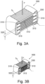
- FIG. 3A An example of a standard capacitor 300 is shown in Fig. 3A , and comprises a plurality of conductive sheets 310 (i.e. electrodes) separated by a predetermined distance 320 using a dielectric material 330.
- An active area 312 of the capacitor is defined by an overlap of the conductive sheets 310. If the capacitor 300 is subjected to a change in pressure (shown e.g. by the arrow P in Fig. 3A ) it will deform and the predetermined distance 320 between the conductive sheets 310 will change, thereby changing the capacitance of the capacitor 300. The greater the change in the predetermined distance 320, the greater the change in the capacitance.
- the control unit 180 of the circuit device 120 is arranged to monitor changes in the capacitance of the capacitor 300 (i.e. the pressure senor 150), and is thereby able to monitor changes in the pressure of the surrounding liquid 130 within the housing 110.
- the distance d i.e. the predetermined distance 320
- E Young's modulus of the capacitor in a direction normal to the active area
- p the hydrostatic pressure
- d 0 the original predetermined distance 320 between the conductive sheets 310 of the capacitor 300. Therefore, by using the above expressions, the pressure within the housing 110 may be calculated as a function of the capacitance of the pressure sensor 150.
- the wireless unit 160 necessarily also includes a capacitor 162, but changes in the capacitance of the capacitor 162 of the wireless unit 160 change the resonant frequency of the LC circuit and therefore degrade the efficiency of the circuit for receiving signals e.g. for power and communication.
- the circuit device 120 should comprise a capacitor 162 in the wireless unit 160 that is not sensitive to changes in pressure of the liquid 130 in the housing 110, and on the other hand should comprise a capacitor as a pressure sensor 150 that is sensitive to pressure changes in the liquid 130 in the housing 110.
- the pressure sensor 150 that is provided by a capacitor 300 is arranged to have a larger surface area S p than the corresponding surface area S w of the capacitor 162 of the wireless unit 160.
- Figure 3B shows a standard capacitor 300 which may be used in the LC circuit 160 of the circuit device 120.
- the capacitor 300 of Fig. 3B is the same type as the capacitor 300 of Fig. 3A , and is not specially adapted for use as a pressure sensor. However, it is smaller than the capacitor 300 of Fig. 3A and therefore has a smaller surface area S w than the equivalent surface area S p of the capacitor 300 of Fig. 3A .
- the surface area S of each capacitor is approximately equal to the active area A of the capacitor.
- the pressure sensor 150 may therefore be a capacitor with a larger surface area than that of the capacitor 162 of the LC circuit.
- the pressure sensor 150 and the capacitor 162 of the wireless unit 160 may be the same type of capacitor 300, and may both be simple, standard capacitors.
- the pressure sensor 150 may have a surface area S large enough that the capacitor exhibits changes in its capacitance over the expected range of pressures (e.g. 0 bar to 25 bar), and the capacitor 162 may have a surface area smaller than that of the pressure sensor 150 so that it is substantially insensitive to pressure changes over the expected range.
- the pressure sensor 150 may have a surface area S, more than twice that of the capacitor 162, or more than five times that of the capacitor 162, more than ten times that of the capacitor 162, more than fifty times that of the capacitor 162, or more than a hundred times that of the capacitor 162.
- a second capacitor may be used as a pressure sensor 150 by providing that second capacitor with a larger surface area S.
- the pressure sensor 150 may be sensitive to pressure changes in the liquid 130, while the capacitor 162 of the wireless unit 162 is not sensitive to pressure changes in the liquid 130.
- the circuit device 120 thus comprises a capacitor 300 arranged to detect changes in pressure in the liquid 130 of the sprinkler bulb 100 by variation of its capacitance.
- the control unit 180 detects the changes in the capacitance of the pressure sensor 150 and may correlate those changes to changes in pressure of the liquid 130. It is therefore possible to test whether or not the sprinkler bulb 100 is in working order, as described above.
- Figure 4 shows an example of various diagnostic ranges during a process for detecting a cracked sprinkler bulb. Different ranges, zones, and values may be used for different configurations of a particular sprinkler bulb.
- the curves a and b of Fig. 4 are a function of the volume of liquid and gas in the housing 110, the type of liquid and gas, the type of material used for the frangible housing 110 etc.
- Figure 4 shows pressure changes in the housing measured by the control unit 180 during testing of the bulb 100 and heating of the liquid 130.
- the horizontal axis indicates the time after the heating unit 170 is activated, and the vertical axis indicates the pressure that is measured at a particular time.
- the heating unit 170 is expected to raise the temperature of the liquid 130, and hence increase the pressure in the housing 110, by a certain amount within a predetermined time period t1.
- the point t1 can therefore be used as a reference point to test the integrity of the bulb 100.
- the pressure starts in an initial pressure zone 410, indicative a pressure range at which the bulb 100 is ready for use e.g. prior to heating or a fire event.
- the pressure of the bulb 100 would be expected to be in this range if intact and when not heated. If the bulb 100 is in working order (i.e. not damaged) the pressure will increase approximately along curve a. That is, the pressure increases with increasing time (i.e. increasing temperature). Heating of the liquid 130 is stopped at time t1, and the pressure in the housing then falls again as the liquid 130 cools. The pressure therefore does not reach zone 440, wherein the housing 110 of the bulb 100 is expected to break e.g. as would be the case in a fire event. However, the pressure does enter zone 430 in which the pressure of the liquid 130 increases with time and reaches a relatively high level. Zone 430 is therefore indicative of an intact bulb 100, and hence a bulb 100 which is in working order.
- the pressure in the housing 110 will not reach zone 440, or even zone 430, and will not be sufficient to cause the housing 110 to shatter, despite the continued application of heat to the liquid 130 of the bulb 100. Therefore, the sprinkler bulb 100 is not safe to use.
- the temperature sensor 172 of the circuit can be used to check that temperature is increasing as expected, to ensure that diagnoses may be attributed to the condition of the housing 110, rather that e.g. a faulty heating unit 170.
- the circuit device 120 may have a width of about 1mm to 10mm, and a length of about 10mm to 25mm.
- the circuit device 120 may have a size of about 3mm by 18mm.
- the circuit device may have any suitable size so that it fits within a conventional sprinkler bulb.
- Capacitors are typically standard sizes, and since the pressure sensor 150 may be simple capacitor (e.g. not specially adapted for use as a pressure sensor), it may be selected from standard industry-used sizes.
- the capacitor 162 of the wireless unit 160 may similarly be selected from standard sizes. Standard capacitor sizes are typically expressed as a 4-digit code indicating the width and length dimensions in fractions of an inch. For example, a 0805 capacitor has a width of about 0.08" (2mm) and a length of about 0.05" (1mm).
- the pressure sensor 150 may be one standard size larger than the capacitor 162 of the wireless unit 160, or may be a plurality of standard sizes larger.
- the pressure sensor may be a 0805 capacitor (i.e. 2.0mm by 1.25mm), and the capacitor 162 of the wireless unit 160 may be a 0402 capacitor (i.e. 1.0mm by 0.5mm), or a 0201 capacitor (e.g. 0.6mm by 0.3mm).
- autonomous and remote testing of sprinkler bulbs 100 may be accomplished. Bulbs 100 may be checked regularly by a central system and faulty bulbs 100 may be flagged for replacement. Further, the invention provides a simple and reliable pressure sensor 150 by recognising that a capacitor 300 may be used as a pressure sensor 150, so long as it is sized appropriately to be sensitive to ambient pressure changes.
Landscapes
- Health & Medical Sciences (AREA)
- Public Health (AREA)
- Business, Economics & Management (AREA)
- Emergency Management (AREA)
- Physics & Mathematics (AREA)
- General Physics & Mathematics (AREA)
- Fire-Extinguishing By Fire Departments, And Fire-Extinguishing Equipment And Control Thereof (AREA)
- Measuring Fluid Pressure (AREA)
Claims (14)
- Sprinklerkolben, der ein abgedichtetes, zerbrechliches Gehäuse (110), das ein Fluid (130) enthält, und eine Schaltungsvorrichtung (120) innerhalb des Gehäuses umfasst, wobei die Schaltungsvorrichtung (120) innerhalb des Fluids (130) angeordnet ist und umfasst:einen Kondensator (150), der dazu eingerichtet ist, als Drucksensor zum Erfassen von Druckänderungen innerhalb des Gehäuses (110) verwendet zu werden;ein Heizelement (170), das dazu betreibbar ist, das Fluid (130) innerhalb des Gehäuses (110) des Sprinklerkolbens zu erhitzen, undeine Steuereinheit (180), die dazu konfiguriert ist, Änderungen der Kapazität des Kondensators (150) zu überwachen und dadurch den Kondensator (150) als einen Drucksensor zu verwenden.
- Sprinklerkolben nach Anspruch 1, wobei die Schaltungsvorrichtung (120) dazu eingerichtet ist, eine Änderung einer Kapazität des Kondensators (150) zu erfassen.
- Sprinklerkolben nach Anspruch 1 oder 2, wobei der Kondensator (150) eine Vielzahl leitfähiger Schichten (310) umfasst, die durch einen vorbestimmten Abstand (320) getrennt sind, und wobei der Kondensator (150) dazu eingerichtet ist, sich unter Druck derart zu verformen, dass sich der vorbestimmte Abstand (320) ändert.
- Sprinklerkolben nach einem vorstehenden Anspruch, wobei der Kondensator (150) ein erster Kondensator ist, wobei die Schaltungsvorrichtung (120) eine drahtlose Einheit (160) zum drahtlosen Empfangen von Strom und/oder Signalen von außerhalb des Gehäuses (110) umfasst, und wobei die drahtlose Einheit (160) einen zweiten Kondensator (162) umfasst.
- Sprinklerkolben nach Anspruch 4, wobei eine Änderung einer Kapazität des ersten Kondensators (150) bei Druck größer ist als eine Änderung einer Kapazität des zweiten Kondensators (162) bei Druck.
- Sprinklerkolben nach Anspruch 4 oder 5, wobei der erste Kondensator (150) eine größere Oberfläche aufweist als der zweite Kondensator (162).
- Sprinklerkolben nach einem vorstehenden Anspruch, wobei der Kondensator (150) ein einfacher Kondensator ist.
- Sprinklerkolben nach einem vorstehenden Anspruch, wobei der Kondensator (150) dazu eingerichtet ist, verwendet zu werden, um Druck bis zu etwa 2,5 MPa zu messen.
- Sprinkler, der einen Kolben nach einem vorstehenden Anspruch umfasst, wobei der Kolben dazu eingerichtet ist, das Freisetzen eines Unterdrückungsmittels zu verhindern, solange er nicht bricht.
- Sprinklersystem, das einen Sprinklerkolben nach einem der Ansprüche 1 bis 8 oder einen Sprinkler nach Anspruch 9 umfasst, das eine Systemsteuereinheit umfasst, die dazu eingerichtet ist, die Schaltungsvorrichtung (120) des Sprinklerkolbens zu veranlassen, Fluid (130) in dem Kolben zu erhitzen, um den Druck des Fluids (130) innerhalb des Kolbens unter Verwendung des Kondensators (150) zu messen und zu bestimmen, dass der Kolben in funktionsfähigem Zustand ist, wenn der gemessene Druck einen vorbestimmten Schwellenwert erreicht, und zu bestimmen, dass der Kolben nicht in funktionsfähigem Zustand ist, wenn der gemessene Druck den vorbestimmten Schwellenwert nicht erreicht.
- Verfahren zum Testen eines Sprinklerkolbens, umfassend:Messen des Drucks in einem Sprinklerkolben, der ein abgedichtetes, zerbrechliches Gehäuse (110), das Fluid enthält, und eine Schaltungsvorrichtung (120) innerhalb des Gehäuses umfasst und die und innerhalb des Fluids angeordnet ist, wobei das Verfahren das Verwenden eines Kondensators (150) der Schaltungsvorrichtung als einen Drucksensor zum Erfassen von Druckänderungen innerhalb des Gehäuses umfasst; unddas weiter das Erhitzen von Fluid (130) in dem Gehäuse (110) und das Bestimmen umfasst, dass der Kolben in funktionsfähigem Zustand ist, wenn der Druck in dem Gehäuse (110) einen vorbestimmten Schwellenwert erreicht, und das Bestimmen, dass der Kolben nicht in funktionsfähigem Zustand ist, wenn der Druck in dem Gehäuse (110) den vorbestimmten Schwellenwert nicht erreicht.
- Verfahren nach Anspruch 11, das das Bestimmen einer Druckänderung innerhalb des Gehäuses (110) basierend auf einer Kapazitätsänderung des Kondensators (150) umfasst.
- Verfahren nach Anspruch 11 oder 12, wobei der Kondensator (150) ein erster Kondensator ist, wobei das Verfahren das Bereitstellen einer drahtlosen Einheit (160) zum drahtlosen Empfangen von Energie und/oder Signalen von außerhalb des Gehäuses (110) als Teil der Schaltungsvorrichtung (120) und das Bereitstellen eines zweiten Kondensators (162) als Teil der drahtlosen Einheit (160) umfasst, der eine Kapazität aufweist, die gegenüber Druckänderungen weniger empfindlich ist als die des ersten Kondensators (150).
- Verfahren nach Anspruch 13, das das Bereitstellen des zweiten Kondensators (162) derart umfasst, dass er eine kleinere Oberfläche aufweist als der erste Kondensator (150).
Priority Applications (4)
| Application Number | Priority Date | Filing Date | Title |
|---|---|---|---|
| EP19180660.3A EP3753607B1 (de) | 2019-06-17 | 2019-06-17 | Sprinklerkolben |
| ES19180660T ES3013410T3 (en) | 2019-06-17 | 2019-06-17 | Sprinkler bulb |
| US16/902,975 US12268911B2 (en) | 2019-06-17 | 2020-06-16 | Sprinkler bulb |
| CN202010553980.3A CN112090009A (zh) | 2019-06-17 | 2020-06-17 | 喷洒器球管 |
Applications Claiming Priority (1)
| Application Number | Priority Date | Filing Date | Title |
|---|---|---|---|
| EP19180660.3A EP3753607B1 (de) | 2019-06-17 | 2019-06-17 | Sprinklerkolben |
Publications (3)
| Publication Number | Publication Date |
|---|---|
| EP3753607A1 EP3753607A1 (de) | 2020-12-23 |
| EP3753607B1 true EP3753607B1 (de) | 2025-02-26 |
| EP3753607C0 EP3753607C0 (de) | 2025-02-26 |
Family
ID=66951805
Family Applications (1)
| Application Number | Title | Priority Date | Filing Date |
|---|---|---|---|
| EP19180660.3A Active EP3753607B1 (de) | 2019-06-17 | 2019-06-17 | Sprinklerkolben |
Country Status (4)
| Country | Link |
|---|---|
| US (1) | US12268911B2 (de) |
| EP (1) | EP3753607B1 (de) |
| CN (1) | CN112090009A (de) |
| ES (1) | ES3013410T3 (de) |
Families Citing this family (2)
| Publication number | Priority date | Publication date | Assignee | Title |
|---|---|---|---|---|
| ES3013410T3 (en) * | 2019-06-17 | 2025-04-11 | Marioff Corp Oy | Sprinkler bulb |
| EP4085975A1 (de) * | 2021-05-07 | 2022-11-09 | Marioff Corporation OY | Glaskörpervorrichtung |
Citations (1)
| Publication number | Priority date | Publication date | Assignee | Title |
|---|---|---|---|---|
| US20020053440A1 (en) * | 2000-05-02 | 2002-05-09 | Gil Jong Jin | Thermal ampoule for sprinkler |
Family Cites Families (46)
| Publication number | Priority date | Publication date | Assignee | Title |
|---|---|---|---|---|
| US3884304A (en) * | 1972-07-24 | 1975-05-20 | Robert P Messerschmidt | Fire safety systems |
| US4523474A (en) * | 1983-08-12 | 1985-06-18 | Borg-Warner Corporation | Capacitive pressure sensor |
| AU6390586A (en) * | 1986-03-04 | 1987-09-10 | Total Walther Feuerschutz Gmbh | Sprinkler for automatic fire extinguishing |
| US4741214A (en) * | 1986-09-19 | 1988-05-03 | Combustion Engineering, Inc. | Capacitive transducer with static compensation |
| DE3819749A1 (de) * | 1988-06-10 | 1989-12-14 | Verband Der Sachversicherer Ev | Thermische ausloesevorrichtung fuer sprinkler fuer ortsfeste feuerloeschanlagen |
| DE3909185A1 (de) * | 1989-03-21 | 1990-09-27 | Endress Hauser Gmbh Co | Kapazitiver drucksensor und verfahren zu seiner herstellung |
| DE4013887A1 (de) | 1989-05-26 | 1990-11-29 | Wolfen Filmfab Veb | Verfahren zur druckmessung und einen kapazitiven druckmesswandler dafuer |
| US5301553A (en) * | 1989-12-20 | 1994-04-12 | Tjs Development Corporation | Apparatus for remote sensing and receiving |
| KR100234941B1 (ko) * | 1991-02-28 | 1999-12-15 | 괴란 순트홀름 | 소화용스프레이헤드 |
| FI90394C (sv) * | 1992-04-23 | 1994-02-10 | Goeran Sundholm | Eldsläckningsanordning |
| US5317918A (en) * | 1992-05-18 | 1994-06-07 | Lew Hyok S | High resolution pressure sensor |
| US5628367A (en) * | 1994-11-08 | 1997-05-13 | The Viking Corporation | Temperature sensitive sprinkler head with improved spring |
| US5485345A (en) * | 1994-11-14 | 1996-01-16 | Texas Instruments Incorporated | Pressure transducer apparatus |
| GB9620598D0 (en) * | 1996-10-03 | 1996-11-20 | Grinnell Mfg Uk Ltd | Thermally responsive frangible bulb |
| WO1999053286A1 (de) | 1998-04-09 | 1999-10-21 | Ploechinger Heinz | Kapazitive druck- oder kraftsensorstruktur und verfahren zur herstellung derselben |
| US6789429B2 (en) | 1999-08-06 | 2004-09-14 | Setra System, Inc. | Capacitive pressure sensor having encapsulated resonating components |
| DE10056778A1 (de) * | 2000-11-16 | 2002-09-05 | Kretzschmar Uwe | Brandschutzanlage mit Glasfasssensoren |
| US6715360B1 (en) * | 2003-02-19 | 2004-04-06 | Fisher Controls International, Llc | Gauge pressure sensor for hazardous applications |
| AU2005265506B2 (en) * | 2004-07-28 | 2009-07-30 | Hyun-Soo Kil | Thermosensitive sprinkler |
| CN1754588A (zh) | 2004-09-29 | 2006-04-05 | 青岛东洋警报电子有限公司 | 一种防灾灭火系统 |
| US7089798B2 (en) | 2004-10-18 | 2006-08-15 | Silverbrook Research Pty Ltd | Pressure sensor with thin membrane |
| EP1748237B1 (de) * | 2005-07-22 | 2008-01-02 | Job Lizenz GmbH & Co. KG | Sicherheitsventil für einen Druckgasbehälter |
| US20070074579A1 (en) | 2005-10-03 | 2007-04-05 | Honeywell International Inc. | Wireless pressure sensor and method of forming same |
| US7383737B1 (en) | 2007-03-29 | 2008-06-10 | Delphi Technologies, Inc | Capacitive pressure sensor |
| US7806001B1 (en) * | 2007-06-05 | 2010-10-05 | Orbital Research Inc. | Multi-diaphragm pressure sensors |
| US7765875B2 (en) * | 2007-12-31 | 2010-08-03 | Rosemount Aerospace Inc. | High temperature capacitive static/dynamic pressure sensors |
| EP2113760A1 (de) | 2008-04-30 | 2009-11-04 | Delphi Technologies, Inc. | Kapazitiver Drucksensor |
| EP2489411A1 (de) * | 2011-02-17 | 2012-08-22 | Minimax GmbH & Co KG | Energieunabhängige Auslöseeinrichtung für eine gesteuerte Löscheinrichtung |
| DE202012100623U1 (de) * | 2012-02-24 | 2012-03-22 | Job Lizenz Gmbh & Co. Kg | Brandschutzeinrichtung für elektrische Kleingeräte |
| US8984952B2 (en) * | 2012-09-07 | 2015-03-24 | Dynisco Instruments Llc | Capacitive pressure sensor |
| US9012103B2 (en) * | 2013-02-05 | 2015-04-21 | GM Global Technology Operations LLC | Sensor integrated glass bulb temperature pressure relief device design for hydrogen storage systems |
| DE202014101880U1 (de) * | 2014-04-22 | 2014-05-13 | Job Lizenz Gmbh & Co Kg | Kompakte Miniatur-Feuerlösch- bzw. Brandschutzeinrichtung |
| WO2016048190A1 (ru) * | 2014-09-22 | 2016-03-31 | Общество С Ограниченной Ответственностью "Форносовский Литейно-Механический Завод" | Быстродействующий спринклер |
| RU2652587C2 (ru) * | 2015-11-18 | 2018-04-26 | Общество С Ограниченной Ответственностью "Форносовский Литейно-Механический Завод" | Спринклер с контролем срабатывания |
| EP3454951B1 (de) * | 2016-05-10 | 2022-10-19 | Fike Corporation | Intelligente temperatur- und druckmessanordnung |
| RU2651422C1 (ru) * | 2016-11-10 | 2018-04-19 | ООО "Форносовское научно-производственное предприятие "Гефест" | Разрывная капсула для теплового замка |
| US20180200552A1 (en) * | 2017-01-16 | 2018-07-19 | Shalom Wertsberger | Fire containment system, devices and methods for same and for firefighting systems |
| CN107014438B (zh) | 2017-04-24 | 2019-05-10 | 西北工业大学 | 基于陶瓷封装的高温高压液体压力、温度测量传感器 |
| DE202017103682U1 (de) * | 2017-06-21 | 2018-09-24 | Job Lizenz Gmbh & Co. Kg | Thermisches Auslöseelement |
| EP3597274B1 (de) * | 2018-07-16 | 2023-03-01 | Marioff Corporation OY | Sprinkleranlage mit einem sprinkler und einem identifizierungsgerät |
| ES2925388T3 (es) * | 2018-09-13 | 2022-10-17 | Marioff Corp Oy | Rociador contra incendios con función de liberación remota |
| EP3662976B1 (de) * | 2018-12-05 | 2022-06-01 | Marioff Corporation OY | Risserkennungsfunktion für eine sprinkleranlage mit zerbrechlichem kolben |
| DE102018132859A1 (de) * | 2018-12-19 | 2020-06-25 | Minimax Viking Research & Development Gmbh | Elektrisch auslösbares Schmelzlotöffnungselement eines löschfluidleitenden Elementes |
| EP3702003B1 (de) * | 2019-03-01 | 2021-04-28 | Marioff Corporation OY | Sprinklerkopf mit einem kolben mit eingebettetem rfid-schaltkreis |
| ES3013410T3 (en) * | 2019-06-17 | 2025-04-11 | Marioff Corp Oy | Sprinkler bulb |
| ES2984526T3 (es) * | 2019-09-20 | 2024-10-29 | Marioff Corp Oy | Sistema de extinción de incendios |
-
2019
- 2019-06-17 ES ES19180660T patent/ES3013410T3/es active Active
- 2019-06-17 EP EP19180660.3A patent/EP3753607B1/de active Active
-
2020
- 2020-06-16 US US16/902,975 patent/US12268911B2/en active Active
- 2020-06-17 CN CN202010553980.3A patent/CN112090009A/zh active Pending
Patent Citations (1)
| Publication number | Priority date | Publication date | Assignee | Title |
|---|---|---|---|---|
| US20020053440A1 (en) * | 2000-05-02 | 2002-05-09 | Gil Jong Jin | Thermal ampoule for sprinkler |
Non-Patent Citations (1)
| Title |
|---|
| TAKAHATA KENICHI ET AL: "A Micromachined Capacitive Pressure Sensor Using a Cavity-Less Structure with Bulk-Metal/Elastomer Layers and Its Wireless Telemetry Application", SENSORS, vol. 8, no. 4, 2 April 2008 (2008-04-02), CH, pages 2317 - 2330, XP093139315, ISSN: 1424-8220, Retrieved from the Internet <URL:https://citeseerx.ist.psu.edu/document?repid=rep1&type=pdf&doi=122221a3ff07647971e5b6aa235e38333c1856ed> [retrieved on 20240308], DOI: 10.3390/s8042317 * |
Also Published As
| Publication number | Publication date |
|---|---|
| US12268911B2 (en) | 2025-04-08 |
| US20200391064A1 (en) | 2020-12-17 |
| ES3013410T3 (en) | 2025-04-11 |
| EP3753607A1 (de) | 2020-12-23 |
| CN112090009A (zh) | 2020-12-18 |
| EP3753607C0 (de) | 2025-02-26 |
Similar Documents
| Publication | Publication Date | Title |
|---|---|---|
| EP3753607B1 (de) | Sprinklerkolben | |
| JP5383152B2 (ja) | 圧力測定変換器、圧力測定変換器の状態監視方法および圧力センサ | |
| US12251588B2 (en) | Fire system | |
| US11738223B2 (en) | Fire suppression system | |
| RU2561841C2 (ru) | Противопожарная управляющая система | |
| CN112312976B (zh) | 用于带有易碎泡状物的消防喷洒器的裂纹检测功能 | |
| KR101774105B1 (ko) | 원격 감시 제어 가능한 위험물 시스템 | |
| US10352801B2 (en) | Intelligent temperature and pressure gauge assembly | |
| RU2695425C9 (ru) | Система подавления и локализации | |
| JP2019523872A5 (de) | ||
| BR112012002013B1 (pt) | Sensores de integridade e sistema de sensoreamento da integridade de dispositivo de alívio de pressão, equipamento de alívio de pressão para sistema pressurizado e métodos e equipamento para monitorar dispositivo de alívio de pressão | |
| CN115773964B (zh) | 电气开关装置的气体填料的寿命预测 | |
| JP3037776U (ja) | 低圧検知装置 | |
| HK40049297A (en) | Fire suppression system | |
| JP6486761B2 (ja) | 絶縁構造体、絶縁構造体のリーク検査方法及びシーズヒータ | |
| US11441965B2 (en) | Autonomous and irreversible pressure variation detector | |
| US9903909B2 (en) | Process measuring device for a measuring and control technology | |
| CN108204474A (zh) | 安全泄放装置 | |
| JPS63285301A (ja) | 圧力変動時間の差を求めてアキユムレ−タを監視する装置 | |
| JP2024516872A (ja) | 安全締結具 |
Legal Events
| Date | Code | Title | Description |
|---|---|---|---|
| PUAI | Public reference made under article 153(3) epc to a published international application that has entered the european phase |
Free format text: ORIGINAL CODE: 0009012 |
|
| STAA | Information on the status of an ep patent application or granted ep patent |
Free format text: STATUS: THE APPLICATION HAS BEEN PUBLISHED |
|
| AK | Designated contracting states |
Kind code of ref document: A1 Designated state(s): AL AT BE BG CH CY CZ DE DK EE ES FI FR GB GR HR HU IE IS IT LI LT LU LV MC MK MT NL NO PL PT RO RS SE SI SK SM TR |
|
| AX | Request for extension of the european patent |
Extension state: BA ME |
|
| STAA | Information on the status of an ep patent application or granted ep patent |
Free format text: STATUS: REQUEST FOR EXAMINATION WAS MADE |
|
| 17P | Request for examination filed |
Effective date: 20210623 |
|
| RBV | Designated contracting states (corrected) |
Designated state(s): AL AT BE BG CH CY CZ DE DK EE ES FI FR GB GR HR HU IE IS IT LI LT LU LV MC MK MT NL NO PL PT RO RS SE SI SK SM TR |
|
| STAA | Information on the status of an ep patent application or granted ep patent |
Free format text: STATUS: EXAMINATION IS IN PROGRESS |
|
| P01 | Opt-out of the competence of the unified patent court (upc) registered |
Effective date: 20230527 |
|
| 17Q | First examination report despatched |
Effective date: 20230619 |
|
| GRAP | Despatch of communication of intention to grant a patent |
Free format text: ORIGINAL CODE: EPIDOSNIGR1 |
|
| STAA | Information on the status of an ep patent application or granted ep patent |
Free format text: STATUS: GRANT OF PATENT IS INTENDED |
|
| INTG | Intention to grant announced |
Effective date: 20240918 |
|
| GRAS | Grant fee paid |
Free format text: ORIGINAL CODE: EPIDOSNIGR3 |
|
| GRAA | (expected) grant |
Free format text: ORIGINAL CODE: 0009210 |
|
| STAA | Information on the status of an ep patent application or granted ep patent |
Free format text: STATUS: THE PATENT HAS BEEN GRANTED |
|
| AK | Designated contracting states |
Kind code of ref document: B1 Designated state(s): AL AT BE BG CH CY CZ DE DK EE ES FI FR GB GR HR HU IE IS IT LI LT LU LV MC MK MT NL NO PL PT RO RS SE SI SK SM TR |
|
| REG | Reference to a national code |
Ref country code: GB Ref legal event code: FG4D |
|
| REG | Reference to a national code |
Ref country code: CH Ref legal event code: EP |
|
| REG | Reference to a national code |
Ref country code: DE Ref legal event code: R096 Ref document number: 602019066408 Country of ref document: DE |
|
| REG | Reference to a national code |
Ref country code: IE Ref legal event code: FG4D |
|
| REG | Reference to a national code |
Ref country code: ES Ref legal event code: FG2A Ref document number: 3013410 Country of ref document: ES Kind code of ref document: T3 Effective date: 20250411 |
|
| U01 | Request for unitary effect filed |
Effective date: 20250320 |
|
| P04 | Withdrawal of opt-out of the competence of the unified patent court (upc) registered |
Free format text: CASE NUMBER: APP_14175/2025 Effective date: 20250322 |
|
| U07 | Unitary effect registered |
Designated state(s): AT BE BG DE DK EE FI FR IT LT LU LV MT NL PT RO SE SI Effective date: 20250326 |
|
| U20 | Renewal fee for the european patent with unitary effect paid |
Year of fee payment: 7 Effective date: 20250520 |
|
| PG25 | Lapsed in a contracting state [announced via postgrant information from national office to epo] |
Ref country code: RS Free format text: LAPSE BECAUSE OF FAILURE TO SUBMIT A TRANSLATION OF THE DESCRIPTION OR TO PAY THE FEE WITHIN THE PRESCRIBED TIME-LIMIT Effective date: 20250526 |
|
| PG25 | Lapsed in a contracting state [announced via postgrant information from national office to epo] |
Ref country code: PL Free format text: LAPSE BECAUSE OF FAILURE TO SUBMIT A TRANSLATION OF THE DESCRIPTION OR TO PAY THE FEE WITHIN THE PRESCRIBED TIME-LIMIT Effective date: 20250226 |
|
| PG25 | Lapsed in a contracting state [announced via postgrant information from national office to epo] |
Ref country code: IS Free format text: LAPSE BECAUSE OF FAILURE TO SUBMIT A TRANSLATION OF THE DESCRIPTION OR TO PAY THE FEE WITHIN THE PRESCRIBED TIME-LIMIT Effective date: 20250626 Ref country code: NO Free format text: LAPSE BECAUSE OF FAILURE TO SUBMIT A TRANSLATION OF THE DESCRIPTION OR TO PAY THE FEE WITHIN THE PRESCRIBED TIME-LIMIT Effective date: 20250526 |
|
| PG25 | Lapsed in a contracting state [announced via postgrant information from national office to epo] |
Ref country code: HR Free format text: LAPSE BECAUSE OF FAILURE TO SUBMIT A TRANSLATION OF THE DESCRIPTION OR TO PAY THE FEE WITHIN THE PRESCRIBED TIME-LIMIT Effective date: 20250226 |
|
| PG25 | Lapsed in a contracting state [announced via postgrant information from national office to epo] |
Ref country code: GR Free format text: LAPSE BECAUSE OF FAILURE TO SUBMIT A TRANSLATION OF THE DESCRIPTION OR TO PAY THE FEE WITHIN THE PRESCRIBED TIME-LIMIT Effective date: 20250527 |
|
| PG25 | Lapsed in a contracting state [announced via postgrant information from national office to epo] |
Ref country code: SM Free format text: LAPSE BECAUSE OF FAILURE TO SUBMIT A TRANSLATION OF THE DESCRIPTION OR TO PAY THE FEE WITHIN THE PRESCRIBED TIME-LIMIT Effective date: 20250226 |
|
| PGFP | Annual fee paid to national office [announced via postgrant information from national office to epo] |
Ref country code: ES Payment date: 20250703 Year of fee payment: 7 |
|
| PGFP | Annual fee paid to national office [announced via postgrant information from national office to epo] |
Ref country code: GB Payment date: 20250725 Year of fee payment: 7 |
|
| PG25 | Lapsed in a contracting state [announced via postgrant information from national office to epo] |
Ref country code: CZ Free format text: LAPSE BECAUSE OF FAILURE TO SUBMIT A TRANSLATION OF THE DESCRIPTION OR TO PAY THE FEE WITHIN THE PRESCRIBED TIME-LIMIT Effective date: 20250226 |
|
| PG25 | Lapsed in a contracting state [announced via postgrant information from national office to epo] |
Ref country code: SK Free format text: LAPSE BECAUSE OF FAILURE TO SUBMIT A TRANSLATION OF THE DESCRIPTION OR TO PAY THE FEE WITHIN THE PRESCRIBED TIME-LIMIT Effective date: 20250226 |