EP2510771A1 - Mäh- und/oder Vertikutiermaschine - Google Patents
Mäh- und/oder Vertikutiermaschine Download PDFInfo
- Publication number
- EP2510771A1 EP2510771A1 EP12401054A EP12401054A EP2510771A1 EP 2510771 A1 EP2510771 A1 EP 2510771A1 EP 12401054 A EP12401054 A EP 12401054A EP 12401054 A EP12401054 A EP 12401054A EP 2510771 A1 EP2510771 A1 EP 2510771A1
- Authority
- EP
- European Patent Office
- Prior art keywords
- mowing
- drive shaft
- screw
- vertikutiermaschine
- connecting element
- Prior art date
- Legal status (The legal status is an assumption and is not a legal conclusion. Google has not performed a legal analysis and makes no representation as to the accuracy of the status listed.)
- Granted
Links
Images
Classifications
-
- A—HUMAN NECESSITIES
- A01—AGRICULTURE; FORESTRY; ANIMAL HUSBANDRY; HUNTING; TRAPPING; FISHING
- A01D—HARVESTING; MOWING
- A01D34/00—Mowers; Mowing apparatus of harvesters
- A01D34/01—Mowers; Mowing apparatus of harvesters characterised by features relating to the type of cutting apparatus
- A01D34/412—Mowers; Mowing apparatus of harvesters characterised by features relating to the type of cutting apparatus having rotating cutters
- A01D34/42—Mowers; Mowing apparatus of harvesters characterised by features relating to the type of cutting apparatus having rotating cutters having cutters rotating about a horizontal axis, e.g. cutting-cylinders
- A01D34/49—Mowers; Mowing apparatus of harvesters characterised by features relating to the type of cutting apparatus having rotating cutters having cutters rotating about a horizontal axis, e.g. cutting-cylinders with means for discharging mown material
Definitions
- the invention relates to a mowing and / or Vertikutiermaschine according to the preamble of claim 1.
- Such a mowing and / or Vertikutiermaschine is through the DE 10 2005 006 523 A1 known.
- the worm shaft is coupled by means of a connecting element with the motor-driven drive shaft.
- This connecting element is formed in practice as a sleeve slipped over both shafts, which is positively connected with two shafts to force and positively transfer the rotational movement.
- This connector does not always provide a sufficiently strong connection between the two shafts.
- the invention is based on the object to provide a connecting element for connecting the two shafts together, which on the one hand is designed simply and on the other hand ensures a secure connection of the two shafts together.
- the connecting element is designed as a combined cone and screw connection.
- a simple embodiment of the combined cone and screw connection can be achieved in that the cone and screw connection has an outer cone on the drive shaft and an inner cone in the worm shaft.
- a simple construction of the combined cone and screw connection results from the fact that at the free end of the drive shaft, a screw thread of the screw connection is associated with the outer cone.
- the drive shaft protrudes from a transmission housing.
- the drive shaft protrudes from a housing of a hydraulic motor.
- the mowing and / or Vertikutiermaschine is a versatile device and can be in addition to the mowing of green areas as well Use scarifying and collecting equipment.
- the machine has an unillustrated chassis with the driven front wheels and the rear pendulum wheels. Steering is via the driven front wheels.
- the collecting container On the frame of the machine, the collecting container is arranged on the rear side thereof.
- the mowing and scarifying device 1 designed as a flail or drum mower is arranged so as to be movable in the height direction via a linkage.
- a conveyor trough 3 connects to the cross auger 4.
- the cross auger 4 promotes the good from both sides of the longitudinal screw conveyor 5 to.
- This longitudinal screw conveyor 5 is arranged obliquely pointing backwards at the top and ends in a collecting container.
- the screw conveyor 5 has the conveyor tube 6 and arranged on the worm shaft 7 designed as a screw shaft screw flights 8.
- the screw conveyor 5 is formed town tech.
- the worm threads 8 have a multiplicity of worm windings.
- the worm threads 8 of the screw conveyor 5 promote the Good compacting in the sump, the ends of the worm threads 8 press the material in the reservoir 5 and compact it there.
- the drive shaft 10 is arranged.
- the worm shaft tube 7 is coupled via a connecting element 11 with the drive shaft 10.
- the connecting element 11 is designed as a combined cone and screw connection.
- the cone and screw connection has an outer cone 12 on the drive shaft 10 and an inner cone 13 in the screw shaft 7 designed as a screw shaft.
- a screw thread 13 is the Screw 14 is then assigned.
- the drive shaft 10 protrudes from the transmission housing 15.
- the drive shaft 10 protrudes from the housing of a hydraulic motor.
Landscapes
- Life Sciences & Earth Sciences (AREA)
- Environmental Sciences (AREA)
- Harvester Elements (AREA)
Abstract
Description
- Die Erfindung betrifft eine Mäh- und/oder Vertikutiermaschine gemäß des Oberbegriffes des Patentanspruches 1.
- Eine derartige Mäh- und/oder Vertikutiermaschine ist durch die
DE 10 2005 006 523 A1 bekannt. Bei dieser Mäh- und/oder Vertikutiermaschine ist die Schneckenwelle mittels eines Verbindungselementes mit der motorisch angetriebenen Antriebswelle gekuppelt. Dieses Verbindungselement ist in der Praxis als eine über beide Wellen gestülpte Hülse ausgebildet, welche formschlüssig mit beiden Wellen verbunden ist, um die Drehbewegung kraft- und formschlüssig zu übertragen. Dieses Verbindungselement schafft nicht immer eine ausreichend feste Verbindung zwischen den beiden Wellen. - Weiterhin ist aufgrund der Ausgestaltung des Verbindungselementes das Lösen der Schneckenwelle von der Antriebswelle zu Reparaturzwecken und/oder Wartungszwecken relativ aufwändig.
- Der Erfindung liegt die Aufgabe zu Grunde, ein Verbindungselement zum Verbinden der beiden Wellen miteinander zu schaffen, welches einerseits einfach ausgestaltet ist und andererseits eine sichere Verbindung der beiden Wellen miteinander gewährleistet.
- Diese Aufgabe wird erfindungsgemäß dadurch gelöst, dass das Verbindungselement als kombinierte Konus- und Schraubverbindung ausgebildet ist. Infolge dieser Maßnahme ergibt sich über das erfindungsgemäße ausgestaltete Verbindungselement, dass durch die Konusverbindung eine sehr genaue Justierung der Wellen zueinander erfolgt. Weiterhin wird durch die kombinierte Konus- und Schraubverbindung eine gute Kraftübertragung erreicht.
- Eine einfache Ausgestaltung der kombinierten Konus- und Schraubverbindung, lässt sich dadurch erreichen, dass die Konus- und Schraubverbindung einen Außenkonus auf der Antriebswelle und einen Innenkonus in der Schneckenwelle aufweist.
- Ein einfacher Aufbau der kombinierten Konus- und Schraubverbindung, ergibt sich dadurch, dass an dem freien Ende der Antriebswelle ein Schraubengewinde der Schraubverbindung dem Außenkonus sich anschließend zugeordnet ist.
- In einer Ausführungsform ist vorgesehen, dass die Antriebswelle aus einem Getriebegehäuse herausragt.
- In einer anderen Ausführungsform ist vorgesehen, dass die Antriebswelle aus einem Gehäuse eines Hydraulikmotors herausragt.
- Weitere Einzelheiten der Erfindung sind der
- Beispielsbeschreibung und den Zeichnungen zu entnehmen. Hierbei zeigen
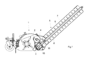
- Fig. 1
- die Mäh- und/oder Vertikutiereinrichtung der Mäh- und/oder Vertikutiermaschine in Seitenansicht, Teilschnitt und in Prinzipdarstellung und
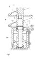
- Fig. 2
- die Verbindung der Antriebswelle und der Schneckenwelle mittels des erfindungsgemäßen Verbindungselementes im Schnitt und in einem vergrößerten Maßstab.
- Die Mäh- und/oder Vertikutiermaschine ist ein vielseitiges Gerät und lässt sich neben dem Mähen von Grünflächen auch als Vertikutier- und Aufsammelgerät einsetzen. Die Maschine weist ein nicht dargestelltes Fahrwerk mit den angetriebenen Vorderrädern und den hinteren Pendelrädern auf. Die Lenkung erfolgt über die angetriebenen Vorderräder. An dem Rahmen der Maschine ist auf dessen Rückseite der Sammelbehälter angeordnet. Auf der Vorderseite der Maschine ist über eine Anlenkung die als Schlegel- oder Trommelmähwerk ausgebildete Mäh- und Vertikutiereinrichtung 1 in Höhenrichtung bewegbar angeordnet. An das Gehäuse 2 der Mäh- und Vertikutiereinrichtung 1 schließt sich ein Fördertrog 3 mit der Querförderschnecke 4 an. Die Querförderschnecke 4 fördert das Gut von beiden Seiten der Längsförderschnecke 5 zu. Diese Längsförderschnecke 5 ist schräg nach hinten oben weisend angeordnet und endet in einem Sammelbehälter. Die Förderschnecke 5 weist das Förderrohr 6 und die auf der als Schneckenwellenrohr ausgebildeten Schneckenwelle 7 angeordneten Schneckengänge 8 auf. Die Förderschnecke 5 ist zweigängig ausgebildet. Die Schneckengänge 8 weisen eine Vielzahl von Schneckenwindungen auf. Die Schneckengänge 8 der Förderschnecke 5 fördern das Gut verdichtend in den Sammelbehälter, wobei die Enden der Schneckengänge 8 das Gut in den Vorratsbehälter 5 pressen und es dort verdichten.
- An dem unteren Ende 9 des Schneckenwellrohres 7 ist die Antriebswelle 10 angeordnet. Das Schneckenwellenrohr 7 ist über ein Verbindungselement 11 mit der Antriebswelle 10 gekuppelt. Das Verbindungselement 11 ist als kombinierte Konus- und Schraubverbindung ausgebildet. Die Konus- und Schraubverbindung weist einen Außenkonus 12 auf der Antriebswelle 10 und einen Innenkonus 13 in der als Schneckenrohr 7 ausgebildeten Schneckenwelle auf. An dem freien Ende der Antriebswelle 10, das heißt im Anschluss an den Außenkonus 12, ist ein Schraubengewinde 13 der Schraubverbindung 14 sich anschließend zugeordnet. Die Antriebswelle 10 ragt aus dem Getriebegehäuse 15 heraus.
- Es ist auch möglich, dass die Antriebswelle 10 aus dem Gehäuse eines Hydraulikmotors herausragt.
Claims (5)
- Mäh- und/oder Vertikutiermaschine mit einer Mäh- und/oder Vertikutiereinrichtung, die das abgeschnittene und/oder aus dem Boden entfernte Gut einem Sammelbehälter über eine ein Förderrohr und Schneckengänge aufweisende Förderschnecke zuführt, wobei die die Schneckengänge tragende Schneckenwelle zumindest an ihrem unteren Ende gelagert und von einer motorisch angetriebenen Antriebswelle rotierend antreibbar ist, wobei die Schneckenwelle mittels eines Verbindungselementes mit der Antriebswelle gekuppelt ist, dadurch gekennzeichnet, dass das Verbindungselement (11) als kombinierte Konus- und Schraubverbindung (12, 13, 14) ausgebildet ist.
- Mäh- und/oder Vertikutiermaschine nach Anspruch 1, dadurch gekennzeichnet, dass die Konus- und Schraubverbindung (11) einen Außenkonus (12) auf der Antriebswelle (10) und einen Innenkonus (13) in der Schneckenwelle aufweist.
- Mäh- und/oder Vertikutiermaschine nach zumindest einem der vorstehenden Ansprüche, dadurch gekennzeichnet, dass an dem freien Ende der Antriebswelle (10) ein Schraubengewinde (14) der Schraubverbindung dem Außenkonus (12) sich anschließend zugeordnet ist.
- Mäh- und/oder Vertikutiermaschine nach zumindest einem der vorstehenden Ansprüche, dadurch gekennzeichnet, dass die Antriebswelle (10) aus einem Getriebegehäuse (15) herausragt.
- Mäh- und/oder Vertikutiermaschine nach zumindest einem der vorstehenden Ansprüche, dadurch gekennzeichnet, dass die Antriebswelle aus einem Gehäuse eines Hydraulikmotors herausragt.
Applications Claiming Priority (1)
| Application Number | Priority Date | Filing Date | Title |
|---|---|---|---|
| DE201110002036 DE102011002036A1 (de) | 2011-04-14 | 2011-04-14 | Mäh- und/oder Vertikutiermaschine |
Publications (2)
| Publication Number | Publication Date |
|---|---|
| EP2510771A1 true EP2510771A1 (de) | 2012-10-17 |
| EP2510771B1 EP2510771B1 (de) | 2014-06-18 |
Family
ID=45977323
Family Applications (1)
| Application Number | Title | Priority Date | Filing Date |
|---|---|---|---|
| EP20120401054 Active EP2510771B1 (de) | 2011-04-14 | 2012-04-02 | Mäh- und/oder Vertikutiermaschine |
Country Status (2)
| Country | Link |
|---|---|
| EP (1) | EP2510771B1 (de) |
| DE (1) | DE102011002036A1 (de) |
Families Citing this family (2)
| Publication number | Priority date | Publication date | Assignee | Title |
|---|---|---|---|---|
| WO2015028954A1 (en) * | 2013-08-28 | 2015-03-05 | Husqvarna Ab | Articulated rider collection assembly |
| DE102017122280A1 (de) * | 2017-09-26 | 2019-03-28 | Amazonen-Werke H. Dreyer Gmbh & Co. Kg | Mobile Bearbeitungseinheit |
Citations (3)
| Publication number | Priority date | Publication date | Assignee | Title |
|---|---|---|---|---|
| EP0685148A1 (de) * | 1994-05-30 | 1995-12-06 | Amazone Machines Agricoles S.A. | Mäh- und/oder Vertikutiermaschine |
| DE19607350A1 (de) * | 1996-02-27 | 1997-08-28 | Amazone Machines Agricoles Sa | Mäh- und/oder Vertikutiermaschine |
| DE102005006523A1 (de) | 2005-02-11 | 2006-08-24 | Amazonen-Werke H. Dreyer Gmbh & Co. Kg | Mäh- und Vertikutiermaschine |
-
2011
- 2011-04-14 DE DE201110002036 patent/DE102011002036A1/de not_active Withdrawn
-
2012
- 2012-04-02 EP EP20120401054 patent/EP2510771B1/de active Active
Patent Citations (3)
| Publication number | Priority date | Publication date | Assignee | Title |
|---|---|---|---|---|
| EP0685148A1 (de) * | 1994-05-30 | 1995-12-06 | Amazone Machines Agricoles S.A. | Mäh- und/oder Vertikutiermaschine |
| DE19607350A1 (de) * | 1996-02-27 | 1997-08-28 | Amazone Machines Agricoles Sa | Mäh- und/oder Vertikutiermaschine |
| DE102005006523A1 (de) | 2005-02-11 | 2006-08-24 | Amazonen-Werke H. Dreyer Gmbh & Co. Kg | Mäh- und Vertikutiermaschine |
Also Published As
| Publication number | Publication date |
|---|---|
| DE102011002036A1 (de) | 2012-10-18 |
| EP2510771B1 (de) | 2014-06-18 |
Similar Documents
| Publication | Publication Date | Title |
|---|---|---|
| DE102013008973B4 (de) | Vorrichtung zum Fördern von Fluiden | |
| DE102010052816A1 (de) | Erntevorsatz für eine Erntemaschine | |
| EP2510771B1 (de) | Mäh- und/oder Vertikutiermaschine | |
| EP2386196A1 (de) | Landwirtschaftliche Vorrichtung zum Verfestigen des Bodens | |
| EP2769938B1 (de) | Antriebswellenmodul für eine Baumaschine | |
| DE202013007632U1 (de) | Vorrichtung zum Antreiben zumindest einer Förderschnecke | |
| EP2510772A1 (de) | Mäh- und/oder Vertikutiermaschine | |
| DE102005006523B4 (de) | Mäh- und Vertikutiermaschine | |
| EP2815931A1 (de) | Scheibenwischermotor | |
| DE102012015932A1 (de) | Erntevorsatz für eine Erntemaschine | |
| DE19607350B4 (de) | Mäh- und/oder Vertikutiermaschine | |
| DE102021118849B3 (de) | Portalschneidwerk | |
| DE8600113U1 (de) | Einzugs- und Rippenwalze für den Maispflückvorsatz eines Mähdreschers | |
| DE102009039053B3 (de) | Vorrichtung zum Spalten von Holz | |
| DE2735598A1 (de) | Standgetriebe fuer landwirtschaftliche maschinen | |
| DE29508739U1 (de) | Ballenpresse | |
| EP3097766A1 (de) | Getriebeanordnung für einen ladewagen für halm- und blattgut | |
| EP3197606B1 (de) | Applikationsvorrichtung | |
| EP2607209A1 (de) | Selbstfahrende, wenigstens einachsige Arbeitsmaschine zum Betreiben und/oder Fortbewegen von angebauten Arbeitsgeräten oder angehängten Fahrzeugen | |
| DE3336533C2 (de) | Landwirtschaftliches motorbetriebenes Gerät | |
| DE102010037935A1 (de) | Schleuderdüngerstreuer | |
| DE102010060155B4 (de) | Schleuderdüngerstreuer | |
| EP2184199B1 (de) | Selbstfahrende lenkbare Arbeitsmaschine | |
| DE1921723A1 (de) | Vorrichtung fuer landwirtschaftliche Zwecke | |
| DE19633788C2 (de) | Handgeführter Einachsbalkenmäher |
Legal Events
| Date | Code | Title | Description |
|---|---|---|---|
| PUAI | Public reference made under article 153(3) epc to a published international application that has entered the european phase |
Free format text: ORIGINAL CODE: 0009012 |
|
| AK | Designated contracting states |
Kind code of ref document: A1 Designated state(s): AL AT BE BG CH CY CZ DE DK EE ES FI FR GB GR HR HU IE IS IT LI LT LU LV MC MK MT NL NO PL PT RO RS SE SI SK SM TR |
|
| AX | Request for extension of the european patent |
Extension state: BA ME |
|
| 17P | Request for examination filed |
Effective date: 20130328 |
|
| GRAP | Despatch of communication of intention to grant a patent |
Free format text: ORIGINAL CODE: EPIDOSNIGR1 |
|
| INTG | Intention to grant announced |
Effective date: 20140226 |
|
| RIN1 | Information on inventor provided before grant (corrected) |
Inventor name: SCHOMAEKER, WILFRIED Inventor name: KLEIN, LAURENT |
|
| GRAS | Grant fee paid |
Free format text: ORIGINAL CODE: EPIDOSNIGR3 |
|
| GRAA | (expected) grant |
Free format text: ORIGINAL CODE: 0009210 |
|
| AK | Designated contracting states |
Kind code of ref document: B1 Designated state(s): AL AT BE BG CH CY CZ DE DK EE ES FI FR GB GR HR HU IE IS IT LI LT LU LV MC MK MT NL NO PL PT RO RS SE SI SK SM TR |
|
| REG | Reference to a national code |
Ref country code: GB Ref legal event code: FG4D Free format text: NOT ENGLISH |
|
| REG | Reference to a national code |
Ref country code: CH Ref legal event code: EP |
|
| REG | Reference to a national code |
Ref country code: AT Ref legal event code: REF Ref document number: 672779 Country of ref document: AT Kind code of ref document: T Effective date: 20140715 |
|
| REG | Reference to a national code |
Ref country code: IE Ref legal event code: FG4D Free format text: LANGUAGE OF EP DOCUMENT: GERMAN |
|
| REG | Reference to a national code |
Ref country code: DE Ref legal event code: R096 Ref document number: 502012000902 Country of ref document: DE Effective date: 20140807 |
|
| PG25 | Lapsed in a contracting state [announced via postgrant information from national office to epo] |
Ref country code: CY Free format text: LAPSE BECAUSE OF FAILURE TO SUBMIT A TRANSLATION OF THE DESCRIPTION OR TO PAY THE FEE WITHIN THE PRESCRIBED TIME-LIMIT Effective date: 20140618 Ref country code: NO Free format text: LAPSE BECAUSE OF FAILURE TO SUBMIT A TRANSLATION OF THE DESCRIPTION OR TO PAY THE FEE WITHIN THE PRESCRIBED TIME-LIMIT Effective date: 20140918 Ref country code: FI Free format text: LAPSE BECAUSE OF FAILURE TO SUBMIT A TRANSLATION OF THE DESCRIPTION OR TO PAY THE FEE WITHIN THE PRESCRIBED TIME-LIMIT Effective date: 20140618 Ref country code: LT Free format text: LAPSE BECAUSE OF FAILURE TO SUBMIT A TRANSLATION OF THE DESCRIPTION OR TO PAY THE FEE WITHIN THE PRESCRIBED TIME-LIMIT Effective date: 20140618 Ref country code: GR Free format text: LAPSE BECAUSE OF FAILURE TO SUBMIT A TRANSLATION OF THE DESCRIPTION OR TO PAY THE FEE WITHIN THE PRESCRIBED TIME-LIMIT Effective date: 20140919 |
|
| REG | Reference to a national code |
Ref country code: NL Ref legal event code: VDEP Effective date: 20140618 |
|
| REG | Reference to a national code |
Ref country code: LT Ref legal event code: MG4D |
|
| PG25 | Lapsed in a contracting state [announced via postgrant information from national office to epo] |
Ref country code: HR Free format text: LAPSE BECAUSE OF FAILURE TO SUBMIT A TRANSLATION OF THE DESCRIPTION OR TO PAY THE FEE WITHIN THE PRESCRIBED TIME-LIMIT Effective date: 20140618 Ref country code: LV Free format text: LAPSE BECAUSE OF FAILURE TO SUBMIT A TRANSLATION OF THE DESCRIPTION OR TO PAY THE FEE WITHIN THE PRESCRIBED TIME-LIMIT Effective date: 20140618 Ref country code: RS Free format text: LAPSE BECAUSE OF FAILURE TO SUBMIT A TRANSLATION OF THE DESCRIPTION OR TO PAY THE FEE WITHIN THE PRESCRIBED TIME-LIMIT Effective date: 20140618 Ref country code: SE Free format text: LAPSE BECAUSE OF FAILURE TO SUBMIT A TRANSLATION OF THE DESCRIPTION OR TO PAY THE FEE WITHIN THE PRESCRIBED TIME-LIMIT Effective date: 20140618 |
|
| PG25 | Lapsed in a contracting state [announced via postgrant information from national office to epo] |
Ref country code: CZ Free format text: LAPSE BECAUSE OF FAILURE TO SUBMIT A TRANSLATION OF THE DESCRIPTION OR TO PAY THE FEE WITHIN THE PRESCRIBED TIME-LIMIT Effective date: 20140618 Ref country code: SK Free format text: LAPSE BECAUSE OF FAILURE TO SUBMIT A TRANSLATION OF THE DESCRIPTION OR TO PAY THE FEE WITHIN THE PRESCRIBED TIME-LIMIT Effective date: 20140618 Ref country code: PT Free format text: LAPSE BECAUSE OF FAILURE TO SUBMIT A TRANSLATION OF THE DESCRIPTION OR TO PAY THE FEE WITHIN THE PRESCRIBED TIME-LIMIT Effective date: 20141020 Ref country code: RO Free format text: LAPSE BECAUSE OF FAILURE TO SUBMIT A TRANSLATION OF THE DESCRIPTION OR TO PAY THE FEE WITHIN THE PRESCRIBED TIME-LIMIT Effective date: 20140618 Ref country code: EE Free format text: LAPSE BECAUSE OF FAILURE TO SUBMIT A TRANSLATION OF THE DESCRIPTION OR TO PAY THE FEE WITHIN THE PRESCRIBED TIME-LIMIT Effective date: 20140618 Ref country code: ES Free format text: LAPSE BECAUSE OF FAILURE TO SUBMIT A TRANSLATION OF THE DESCRIPTION OR TO PAY THE FEE WITHIN THE PRESCRIBED TIME-LIMIT Effective date: 20140618 |
|
| PG25 | Lapsed in a contracting state [announced via postgrant information from national office to epo] |
Ref country code: PL Free format text: LAPSE BECAUSE OF FAILURE TO SUBMIT A TRANSLATION OF THE DESCRIPTION OR TO PAY THE FEE WITHIN THE PRESCRIBED TIME-LIMIT Effective date: 20140618 Ref country code: IS Free format text: LAPSE BECAUSE OF FAILURE TO SUBMIT A TRANSLATION OF THE DESCRIPTION OR TO PAY THE FEE WITHIN THE PRESCRIBED TIME-LIMIT Effective date: 20141018 Ref country code: NL Free format text: LAPSE BECAUSE OF FAILURE TO SUBMIT A TRANSLATION OF THE DESCRIPTION OR TO PAY THE FEE WITHIN THE PRESCRIBED TIME-LIMIT Effective date: 20140618 |
|
| REG | Reference to a national code |
Ref country code: DE Ref legal event code: R097 Ref document number: 502012000902 Country of ref document: DE |
|
| PLBE | No opposition filed within time limit |
Free format text: ORIGINAL CODE: 0009261 |
|
| STAA | Information on the status of an ep patent application or granted ep patent |
Free format text: STATUS: NO OPPOSITION FILED WITHIN TIME LIMIT |
|
| PG25 | Lapsed in a contracting state [announced via postgrant information from national office to epo] |
Ref country code: DK Free format text: LAPSE BECAUSE OF FAILURE TO SUBMIT A TRANSLATION OF THE DESCRIPTION OR TO PAY THE FEE WITHIN THE PRESCRIBED TIME-LIMIT Effective date: 20140618 |
|
| 26N | No opposition filed |
Effective date: 20150319 |
|
| PG25 | Lapsed in a contracting state [announced via postgrant information from national office to epo] |
Ref country code: SI Free format text: LAPSE BECAUSE OF FAILURE TO SUBMIT A TRANSLATION OF THE DESCRIPTION OR TO PAY THE FEE WITHIN THE PRESCRIBED TIME-LIMIT Effective date: 20140618 |
|
| PG25 | Lapsed in a contracting state [announced via postgrant information from national office to epo] |
Ref country code: LU Free format text: LAPSE BECAUSE OF FAILURE TO SUBMIT A TRANSLATION OF THE DESCRIPTION OR TO PAY THE FEE WITHIN THE PRESCRIBED TIME-LIMIT Effective date: 20150402 Ref country code: MC Free format text: LAPSE BECAUSE OF FAILURE TO SUBMIT A TRANSLATION OF THE DESCRIPTION OR TO PAY THE FEE WITHIN THE PRESCRIBED TIME-LIMIT Effective date: 20140618 |
|
| REG | Reference to a national code |
Ref country code: CH Ref legal event code: PL |
|
| REG | Reference to a national code |
Ref country code: IE Ref legal event code: MM4A |
|
| PG25 | Lapsed in a contracting state [announced via postgrant information from national office to epo] |
Ref country code: LI Free format text: LAPSE BECAUSE OF NON-PAYMENT OF DUE FEES Effective date: 20150430 Ref country code: CH Free format text: LAPSE BECAUSE OF NON-PAYMENT OF DUE FEES Effective date: 20150430 |
|
| REG | Reference to a national code |
Ref country code: FR Ref legal event code: PLFP Year of fee payment: 5 |
|
| PG25 | Lapsed in a contracting state [announced via postgrant information from national office to epo] |
Ref country code: IE Free format text: LAPSE BECAUSE OF NON-PAYMENT OF DUE FEES Effective date: 20150402 |
|
| GBPC | Gb: european patent ceased through non-payment of renewal fee |
Effective date: 20160402 |
|
| PG25 | Lapsed in a contracting state [announced via postgrant information from national office to epo] |
Ref country code: MT Free format text: LAPSE BECAUSE OF FAILURE TO SUBMIT A TRANSLATION OF THE DESCRIPTION OR TO PAY THE FEE WITHIN THE PRESCRIBED TIME-LIMIT Effective date: 20140618 |
|
| PG25 | Lapsed in a contracting state [announced via postgrant information from national office to epo] |
Ref country code: GB Free format text: LAPSE BECAUSE OF NON-PAYMENT OF DUE FEES Effective date: 20160402 |
|
| REG | Reference to a national code |
Ref country code: FR Ref legal event code: PLFP Year of fee payment: 6 |
|
| PG25 | Lapsed in a contracting state [announced via postgrant information from national office to epo] |
Ref country code: HU Free format text: LAPSE BECAUSE OF FAILURE TO SUBMIT A TRANSLATION OF THE DESCRIPTION OR TO PAY THE FEE WITHIN THE PRESCRIBED TIME-LIMIT; INVALID AB INITIO Effective date: 20120402 Ref country code: SM Free format text: LAPSE BECAUSE OF FAILURE TO SUBMIT A TRANSLATION OF THE DESCRIPTION OR TO PAY THE FEE WITHIN THE PRESCRIBED TIME-LIMIT Effective date: 20140618 Ref country code: BG Free format text: LAPSE BECAUSE OF FAILURE TO SUBMIT A TRANSLATION OF THE DESCRIPTION OR TO PAY THE FEE WITHIN THE PRESCRIBED TIME-LIMIT Effective date: 20140618 |
|
| PG25 | Lapsed in a contracting state [announced via postgrant information from national office to epo] |
Ref country code: TR Free format text: LAPSE BECAUSE OF FAILURE TO SUBMIT A TRANSLATION OF THE DESCRIPTION OR TO PAY THE FEE WITHIN THE PRESCRIBED TIME-LIMIT Effective date: 20140618 |
|
| REG | Reference to a national code |
Ref country code: FR Ref legal event code: PLFP Year of fee payment: 7 |
|
| REG | Reference to a national code |
Ref country code: AT Ref legal event code: MM01 Ref document number: 672779 Country of ref document: AT Kind code of ref document: T Effective date: 20170402 |
|
| PG25 | Lapsed in a contracting state [announced via postgrant information from national office to epo] |
Ref country code: MK Free format text: LAPSE BECAUSE OF FAILURE TO SUBMIT A TRANSLATION OF THE DESCRIPTION OR TO PAY THE FEE WITHIN THE PRESCRIBED TIME-LIMIT Effective date: 20140618 |
|
| PG25 | Lapsed in a contracting state [announced via postgrant information from national office to epo] |
Ref country code: AT Free format text: LAPSE BECAUSE OF NON-PAYMENT OF DUE FEES Effective date: 20170402 |
|
| PG25 | Lapsed in a contracting state [announced via postgrant information from national office to epo] |
Ref country code: AL Free format text: LAPSE BECAUSE OF FAILURE TO SUBMIT A TRANSLATION OF THE DESCRIPTION OR TO PAY THE FEE WITHIN THE PRESCRIBED TIME-LIMIT Effective date: 20140618 |
|
| REG | Reference to a national code |
Ref country code: DE Ref legal event code: R082 Ref document number: 502012000902 Country of ref document: DE Representative=s name: KILBURN & STRODE LLP, GB Ref country code: DE Ref legal event code: R082 Ref document number: 502012000902 Country of ref document: DE Representative=s name: KILBURN & STRODE LLP, NL Ref country code: DE Ref legal event code: R081 Ref document number: 502012000902 Country of ref document: DE Owner name: AMAZONEN-WERKE H. DREYER SE & CO. KG, DE Free format text: FORMER OWNER: AMAZONEN-WERKE H. DREYER GMBH & CO. KG, 49205 HASBERGEN, DE |
|
| REG | Reference to a national code |
Ref country code: DE Ref legal event code: R082 Ref document number: 502012000902 Country of ref document: DE Representative=s name: KILBURN & STRODE LLP, NL |
|
| P01 | Opt-out of the competence of the unified patent court (upc) registered |
Effective date: 20230523 |
|
| PGFP | Annual fee paid to national office [announced via postgrant information from national office to epo] |
Ref country code: DE Payment date: 20250305 Year of fee payment: 14 |
|
| PGFP | Annual fee paid to national office [announced via postgrant information from national office to epo] |
Ref country code: BE Payment date: 20260317 Year of fee payment: 15 Ref country code: IT Payment date: 20260320 Year of fee payment: 15 |
|
| PGFP | Annual fee paid to national office [announced via postgrant information from national office to epo] |
Ref country code: FR Payment date: 20260309 Year of fee payment: 15 |