EP2510169B1 - Tread module - Google Patents
Tread module Download PDFInfo
- Publication number
- EP2510169B1 EP2510169B1 EP20100801198 EP10801198A EP2510169B1 EP 2510169 B1 EP2510169 B1 EP 2510169B1 EP 20100801198 EP20100801198 EP 20100801198 EP 10801198 A EP10801198 A EP 10801198A EP 2510169 B1 EP2510169 B1 EP 2510169B1
- Authority
- EP
- European Patent Office
- Prior art keywords
- module
- tread
- sub
- carrying surface
- load carrying
- Prior art date
- Legal status (The legal status is an assumption and is not a legal conclusion. Google has not performed a legal analysis and makes no representation as to the accuracy of the status listed.)
- Active
Links
Images


Classifications
-
- E—FIXED CONSTRUCTIONS
- E04—BUILDING
- E04F—FINISHING WORK ON BUILDINGS, e.g. STAIRS, FLOORS
- E04F11/00—Stairways, ramps, or like structures; Balustrades; Handrails
- E04F11/02—Stairways; Layouts thereof
- E04F11/104—Treads
-
- E—FIXED CONSTRUCTIONS
- E04—BUILDING
- E04D—ROOF COVERINGS; SKY-LIGHTS; GUTTERS; ROOF-WORKING TOOLS
- E04D13/00—Special arrangements or devices in connection with roof coverings; Protection against birds; Roof drainage ; Sky-lights
- E04D13/12—Devices or arrangements allowing walking on the roof or in the gutter
-
- E—FIXED CONSTRUCTIONS
- E04—BUILDING
- E04B—GENERAL BUILDING CONSTRUCTIONS; WALLS, e.g. PARTITIONS; ROOFS; FLOORS; CEILINGS; INSULATION OR OTHER PROTECTION OF BUILDINGS
- E04B5/00—Floors; Floor construction with regard to insulation; Connections specially adapted therefor
- E04B5/43—Floor structures of extraordinary design; Features relating to the elastic stability; Floor structures specially designed for resting on columns only, e.g. mushroom floors
-
- E—FIXED CONSTRUCTIONS
- E04—BUILDING
- E04F—FINISHING WORK ON BUILDINGS, e.g. STAIRS, FLOORS
- E04F15/00—Flooring
- E04F15/02—Flooring or floor layers composed of a number of similar elements
-
- E—FIXED CONSTRUCTIONS
- E04—BUILDING
- E04F—FINISHING WORK ON BUILDINGS, e.g. STAIRS, FLOORS
- E04F15/00—Flooring
- E04F15/02—Flooring or floor layers composed of a number of similar elements
- E04F15/10—Flooring or floor layers composed of a number of similar elements of other materials, e.g. fibrous or chipped materials, organic plastics, magnesite tiles, hardboard, or with a top layer of other materials
-
- E—FIXED CONSTRUCTIONS
- E04—BUILDING
- E04F—FINISHING WORK ON BUILDINGS, e.g. STAIRS, FLOORS
- E04F15/00—Flooring
- E04F15/22—Resiliently-mounted floors, e.g. sprung floors
-
- E—FIXED CONSTRUCTIONS
- E06—DOORS, WINDOWS, SHUTTERS, OR ROLLER BLINDS IN GENERAL; LADDERS
- E06C—LADDERS
- E06C1/00—Ladders in general
- E06C1/02—Ladders in general with rigid longitudinal member or members
- E06C1/34—Ladders attached to structures, such as windows, cornices, poles, or the like
- E06C1/345—Ladders attached to structures, such as windows, cornices, poles, or the like specially adapted to be installed parallel to the roof surface
Definitions
- This invention relates to a tread module for use in constructing an internal or external walkway or stairway and to a walkway or stairway incorporating said tread module.
- JP 2002 364156A An example of a floor decorative material which is rupturable on-site to reduce the size of the material is described in JP 2002 364156A , where a tread module according to the preamble of claim 1 is disclosed.
- the present invention seeks to provide an improved walkway or stairway and an improved tread module for a walkway or stairway in which at least some of the aforementioned disadvantages of known types of installations and components therefor are mitigated or overcome.
- the present invention seeks in another of its aspects to provide a tread module which facilitates relative ease of installation.
- the present invention seeks in yet another of its aspects to provide a tread module which takes account of the need not to present a significant safety hazard.
- a tread module for a walkway or stairway comprising a body of material which defines a load-carrying surface, said tread module comprising at least two sub-module sections which are formed integrally with one another and inter-connected by at least one severable connecting web formation whereby the tread module may be reduced in size by severance of the severable formation, at least one edge of the tread module being provided with at least one edge protrusion which extends outwards in a direction parallel with the plane of the load carrying surface thereby, in use, to serve to define a spacing between the module and another module or sub-module section against which it is abutted, each of the severable sub-module sections having an edge formation in the form of a flange which extends from the whole of the periphery of the load carrying surface of that section to define together with the underside of the load carrying surface (14) a recess region which is open at said underside surface, said edge formation defining an underside surface of the
- the body may comprise a moulded or cast material. It may be moulded from a plastics material such as a polyamide (e.g. nylon) or a composite such as glass reinforced polyamide. Other suitable materials include cast aluminium.
- a plastics material such as a polyamide (e.g. nylon) or a composite such as glass reinforced polyamide.
- suitable materials include cast aluminium.
- the body preferably is substantially rigid thereby to resist significant deflection in at least one and preferably each of two mutually perpendicular directions.
- At least some of the apertures may be intended, in use of the tread module, to act as drainage channels for drainage of rain water from the load carrying surface.
- apertures may be adapted to locate retention means by which the tread module may be secured to a supporting structure such as part of a roof or a support secured to roof.
- Said apertures may be adapted to accommodate and provide a reaction surface for the head of retention means, such as a bolt, tapered pin or self-tapping screw, whereby the retention means does not need to protrude above the load carrying surface.
- a retention aperture may be of a wedge-like shape in longitudinal cross-section; it may define a frusto-conical shaped surface the diameter of which decreases in a direction away from the load carrying surface, or it may be of a stepped cross-section thereby to define between ends of the aperture an annular abutment surface which lies in a plane substantially parallel with the load carrying surface.
- the body of material defining the load carrying surface may have a thickness direction, being a direction substantially perpendicular to the load carrying surface.
- the body comprises at least one said recess which is open to an underside surface of the body, that underside surface being substantially parallel with the load carrying surface.
- Apertures may be defined by moulded or cast tubular formations such that the or each of a plurality of recesses is defined by the space(s) between the tubular formations
- the severable formations may, for example, be provided substantially midway between two parallel, opposite edges of a body of a substantially square or rectangular shape such that severance of the severable formations results in two tread sub modules of equal dimension, at least as considered in a direction between said opposite edges.
- it may comprise three sections each severable from one another and which may each be of substantially identical size and shape such that the module may be employed to provide either two sub-modules one of two thirds the depth and the other one third of the depth of the original module, or three sub modules each one third of the depth of the original module, the term depth being used herein to refer to the direction of the tread module between the opposite module edges which are separable from one another.
- the tread module for a stairway is of a substantially rectangular shape having a width greater than depth.
- the present invention envisages that advantageously the tread module may be severable into two or more sub module sections each having a greater width to depth ratio than that of the module from which they are formed. Accordingly the tread module may be employed to provide a sub-module of a size which may be employed to complete a length of walkway which is not an exact multiple of the depth of each module. Similarly, for the provision of a steep stairway the module may be reduced in depth to provide stair tread sections of an appropriate, smaller depth.
- the body of the tread module comprises reinforcing web sections extending between neighbouring apertures and/or between apertures and the flange formation which at least in part surrounds said aperture(s) thereby to provide an enhanced reinforcing effect and resistance to deflection of the tread module when the load carrying surface is subjected to an applied load.
- one edge of a tread module is provided with two said edge protrusions and preferably said protrusions are spaced apart by a distance corresponding to the spacing of support members to which it is intended that the tread module may be secured.
- the tread module load carrying surface comprises a plurality of apertures adapted to accommodate retention means for attachment of the module to a reaction surface such as one defined by a pair of elongate support members and preferably two or more of said apertures are spaced apart by a distance corresponding to the spacing of two or more of said aforementioned protrusions provided at an edge of the tread module.
- the rigidity of the tread module allows it to be supported at two edge regions and, without the need for intervening support, resist deflection when loaded between the edge regions.
- the load carrying surface may be provided with texturing for slip resistance purposes.
- the present invention teaches that at least some and optionally all of the apertures may be surrounded by at least one small, raised, rib-like formation.
- an aperture is surrounded by two or more rib-like formations the ends of which are spaced so that water may drain through that spacing into the aperture.
- a preferred configuration is that of a square comprising four straight rib sections each spaced from an adjacent section at a corner of the square.
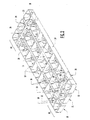
- a tread module 10 for a walkway or stairway comprises an injection moulded body of glass-filled polyamide and of a substantially rectangular shape having a width direction X a depth direction Y and a thickness in the direction Z.
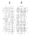
- the module is of a non-solid formation comprising a plurality of through-apertures 11, 12 and a plurality of recess regions 13 which open at an underside surface of the module (see Figures 2 & 3 ).
- Each of the apertures extends from an upper, load carrying surface 14 of the body and is of substantially square profile in plan as viewed in Figure 3 .
- a majority of the apertures serve as drainage apertures 11 but at each edge region 15 there are three retention apertures 12 for receiving retention means (not shown) such as a self-tapping screw by means of which the tread module may be secured to a supporting structure, typically to a pair of extruded aluminium beams which extend in the direction Y and are spaced apart by a distance corresponding to the spacing of the apertures 12 across the width X of the module.
- retention means such as a self-tapping screw
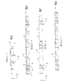
- each drainage aperture is defined by a tubular formation which extends from and is moulded integrally with the material which defines the load carrying surface 14 (see Figures 2 & 5 ).
- the apertures 11 each extends part way through the thickness of the module in the direction Z.
- the retention apertures 12 similarly are formed by tubular formations which extend from and are moulded integrally with the load carrying surface, and have a wall thickness 17 as best seen by reference to Figures 4 and 5 .
- the aperture 12 extends through the entire thickness of the module in the direction Z.
- the retention apertures 12 are substantially closed at a lower end by a shoulder formation 18 provided with a central aperture 19 for a retention screw, the annular shoulder 18 providing an abutment surface against which the head of a retention member may firmly bear.
- the tread module 10 comprises three rows of apertures 11, 12 each extending in the width direction X and each associated with a respective one of three sections 20, 21 & 22 of the load carrying surface 14.
- Each of the load carrying surface sections 20, 21, 22 and the associated apertures defines a sub-module section which is inter-connected to an adjacent sub-module section by integrally moulded and severable connecting webs 23.
- Each of the sub-modules 20, 21, 22 has integrally moulded therewith a flange formation 24 which depends from the periphery of the load carrying surface section and has a length in the thickness direction Z corresponding to that of the apertures 12.
- Reinforcing webs 25 extend between adjacent apertures 11, 12 and between each aperture and confronting surfaces of the flange 24 thereby to provide a reinforcing function.
- One of the longer edges which extends in the width direction of the tread module is provided with a pair of spacers 26 which extend outwards from the flange formation 24.
- Each spacer 26 is aligned with a respective one of the two series of retention apertures 12 whereby, in use when the tread module is supported by a pair of spaced beams extending under the apertures 12, those spacers will each overlie a respective beam.
- Slip-resistance for the load carrying surface 14 is enhanced by surrounding each of the apertures 11, 12 with four rib-like formations 27 arranged in a square formation and with one end of each formation spaced slightly from the side of another rib formation thereby to provide small drainage paths 28 for flow of water from the surface of the load carrying surface into an aperture11.
- pairs of projections 29 may extend downwards from the underside surface of the module.
- the projections optionally may be positioned to extend from those of the severable webs 23 which are aligned with the retention apertures 12.
- the apertures at each end of some or each of the rows of apertures, i.e. onwards of the retention apertures 12, may be provided with coloured or reflective inserts thereby to provide users with a safety indication of the useable extent of a walkway or stairway formed using the modules 10.
- Figure 9 shows an installation comprising a stairway 30 formed from a plurality of the tread modules 10 and a walkway 31 similarly formed from a plurality of the modules and in addition a sub-module 32 formed by severing one of the modules 10 to provide a module of a third the depth of the full module 10 thereby to provide a substantially continuous walkway over a distance which is slightly greater than that which can be wholly occupied by an integral number of the complete modules 10.
- the modules are secured by means of self tapping screws to transversely spaced tubular support beams 32 and are each unsupported between the beams.
Landscapes
- Engineering & Computer Science (AREA)
- Architecture (AREA)
- Structural Engineering (AREA)
- Civil Engineering (AREA)
- Physics & Mathematics (AREA)
- Electromagnetism (AREA)
- Road Paving Structures (AREA)
- Steps, Ramps, And Handrails (AREA)
- Tires In General (AREA)
Priority Applications (1)
| Application Number | Priority Date | Filing Date | Title |
|---|---|---|---|
| PL10801198T PL2510169T3 (pl) | 2009-12-07 | 2010-12-06 | Moduł podnóżka |
Applications Claiming Priority (2)
| Application Number | Priority Date | Filing Date | Title |
|---|---|---|---|
| GB0921366.1A GB2475914B (en) | 2009-12-07 | 2009-12-07 | Tread module for a walkway or stairway with severable sub-module portions |
| PCT/GB2010/002221 WO2011070314A1 (en) | 2009-12-07 | 2010-12-06 | Tread module |
Publications (2)
| Publication Number | Publication Date |
|---|---|
| EP2510169A1 EP2510169A1 (en) | 2012-10-17 |
| EP2510169B1 true EP2510169B1 (en) | 2015-05-06 |
Family
ID=41642020
Family Applications (1)
| Application Number | Title | Priority Date | Filing Date |
|---|---|---|---|
| EP20100801198 Active EP2510169B1 (en) | 2009-12-07 | 2010-12-06 | Tread module |
Country Status (5)
| Country | Link |
|---|---|
| US (1) | US9279256B2 (pl) |
| EP (1) | EP2510169B1 (pl) |
| GB (1) | GB2475914B (pl) |
| PL (1) | PL2510169T3 (pl) |
| WO (1) | WO2011070314A1 (pl) |
Families Citing this family (6)
| Publication number | Priority date | Publication date | Assignee | Title |
|---|---|---|---|---|
| GB2478564B (en) * | 2010-03-10 | 2013-01-02 | Kee Safety Ltd | Walkway assembly |
| US9212491B1 (en) * | 2015-05-22 | 2015-12-15 | Patrick J. Santini | Modular stairway |
| GB2566252A (en) * | 2017-07-13 | 2019-03-13 | Av Coatings Ltd | Roof Board |
| GB2575780B (en) | 2018-07-13 | 2020-08-19 | Kee Safety Ltd | Walkway installation |
| US11572253B2 (en) | 2019-03-15 | 2023-02-07 | John Sund | Incline elevator and modular deck system and methods for the assembly, use and shipping thereof |
| CN114150834B (zh) * | 2021-11-04 | 2023-09-15 | 南通市五洲复合材料有限公司 | 一种高性能全包覆的玻璃钢格栅板及其包覆工艺 |
Family Cites Families (42)
| Publication number | Priority date | Publication date | Assignee | Title |
|---|---|---|---|---|
| US3511001A (en) * | 1968-03-14 | 1970-05-12 | William R Morgan Jr | Resilient leveling means for floors |
| US3909996A (en) * | 1974-12-12 | 1975-10-07 | Economics Lab | Modular floor mat |
| EP0016534A1 (en) * | 1979-02-21 | 1980-10-01 | Ferodo Limited | Improvements in or relating to roof walkways |
| US4436779A (en) * | 1982-07-02 | 1984-03-13 | Menconi K Anthony | Modular surface such as for use in sports |
| US4749302A (en) * | 1983-05-16 | 1988-06-07 | Declute Robert G | Spacing pad |
| US4584221A (en) * | 1984-07-19 | 1986-04-22 | Sportforderung Peter Kung Ag | Floor covering assembly |
| AT388950B (de) * | 1985-11-22 | 1989-09-25 | Spiess Kunststoff Recycling | Gitterplatte aus kunststoff, insbesondere aus recycling-kunststoff |
| US4930809A (en) * | 1988-01-11 | 1990-06-05 | Lindsay Industries, Inc. | Towable unified floor frame assembly |
| DK89291D0 (da) * | 1991-05-13 | 1991-05-13 | Frank Bentzon | Gulvbelaegningssystem med sammenkoblige fliseelementer, navnlig plastfliser |
| US5349795A (en) * | 1993-03-03 | 1994-09-27 | French Terry L | Width-adjustable stairway step tread and method for constructing a stairway therewith |
| NL193982C (nl) * | 1993-10-26 | 2001-04-03 | Hendrik Jan Van Herwijnen | Traploophulpmiddel. |
| US5500267A (en) * | 1994-08-22 | 1996-03-19 | Canning; George | Slip-resistant mat for absorbing oil and other liquids |
| DE59508421D1 (de) * | 1994-12-19 | 2000-07-06 | Sportfoerderung Peter Kueng Ag | Elastisches Kunststoffelement zum Bilden eines Bodenbelages |
| US5527128A (en) * | 1995-05-26 | 1996-06-18 | Portapath International Limited | Ground covering |
| US5787654A (en) * | 1995-09-21 | 1998-08-04 | Sport Court, Inc. | Isogrid tile |
| US5992106A (en) * | 1995-09-21 | 1999-11-30 | Sport Court, Inc. | Hexagon tile with equilateral reinforcement |
| AUPP137798A0 (en) * | 1998-01-16 | 1998-02-05 | Ezydeck Pty Ltd | Decking tile |
| WO2002061206A1 (en) * | 2001-01-29 | 2002-08-08 | Spider Court, Inc. | Modular tile and tile flooring system |
| JP2002364156A (ja) * | 2001-06-11 | 2002-12-18 | Sekisui Chem Co Ltd | 床化粧材 |
| US20030037990A1 (en) * | 2001-08-25 | 2003-02-27 | Testa Vincent M. | Roof and shingle protector arrangement |
| AUPR998002A0 (en) * | 2002-01-17 | 2002-02-07 | Design Develop Commercialise Pty Ltd | Modular plastic flooring |
| US6802159B1 (en) * | 2002-05-31 | 2004-10-12 | Snap Lock Industries, Inc. | Roll-up floor tile system and the method |
| US7028437B2 (en) * | 2002-07-31 | 2006-04-18 | Hauck Robert F | Above-joist, integrated deck-gutter system |
| CA2556881C (en) * | 2004-02-20 | 2011-12-20 | Daniel C. Fuccella | Interlocking modular floor tile |
| US7748177B2 (en) * | 2004-02-25 | 2010-07-06 | Connor Sport Court International, Inc. | Modular tile with controlled deflection |
| US8397466B2 (en) * | 2004-10-06 | 2013-03-19 | Connor Sport Court International, Llc | Tile with multiple-level surface |
| US8407951B2 (en) * | 2004-10-06 | 2013-04-02 | Connor Sport Court International, Llc | Modular synthetic floor tile configured for enhanced performance |
| US8099915B2 (en) * | 2005-06-02 | 2012-01-24 | Snapsports Company | Modular floor tile with resilient support members |
| US7571572B2 (en) * | 2005-06-02 | 2009-08-11 | Moller Jr Jorgen J | Modular floor tile system with sliding lock |
| US7300224B2 (en) * | 2005-10-05 | 2007-11-27 | Slater William B | Support grid platform for supporting vehicles over ecologically sensitive terrain |
| US20090071090A1 (en) * | 2006-01-03 | 2009-03-19 | Feng-Ling Yang | Securing device for combining floor boards |
| JP2007211419A (ja) * | 2006-02-07 | 2007-08-23 | Sakura Color Prod Corp | 階段アート用シート |
| US7571573B2 (en) * | 2006-04-11 | 2009-08-11 | Moller Jr Jorgen J | Modular floor tile with lower cross rib |
| CA2650456A1 (en) * | 2006-04-28 | 2007-11-08 | Albini & Fontanot S.P.A. | Step for modular staircases and relative staircase |
| US8266857B2 (en) * | 2006-09-27 | 2012-09-18 | David Barlow R | Interlocking floor system with barbs for retaining covering |
| CA2672917A1 (en) * | 2006-10-09 | 2008-04-17 | Fieldturf Tarkett Inc. | Tile for a synthetic grass system |
| US7779581B2 (en) * | 2007-05-09 | 2010-08-24 | Ada Solutions, Inc. | Replaceable wet-set tactile warning surface unit and method of installation and replacement |
| CA2702130C (en) * | 2007-10-02 | 2015-06-23 | Fieldturf Tarkett Inc. | Tile for synthetic grass system |
| US7793471B2 (en) * | 2007-11-30 | 2010-09-14 | David Tilghman Hill | Floating floor assembled from an array of interconnected subunits, each of which includes a stone, ceramic, or porcelain tile bonded to an injection molded polyolefin substrate |
| JP2009144461A (ja) * | 2007-12-17 | 2009-07-02 | Takiron Co Ltd | 階段被覆構造及びこれに用いる下地調整材 |
| US8266849B2 (en) * | 2009-05-27 | 2012-09-18 | Mcfarland Cascade Holdings, Inc. | Interlocking platform panels and modules |
| US8505256B2 (en) * | 2010-01-29 | 2013-08-13 | Connor Sport Court International, Llc | Synthetic floor tile having partially-compliant support structure |
-
2009
- 2009-12-07 GB GB0921366.1A patent/GB2475914B/en active Active
-
2010
- 2010-12-06 WO PCT/GB2010/002221 patent/WO2011070314A1/en not_active Ceased
- 2010-12-06 EP EP20100801198 patent/EP2510169B1/en active Active
- 2010-12-06 US US13/514,213 patent/US9279256B2/en active Active
- 2010-12-06 PL PL10801198T patent/PL2510169T3/pl unknown
Also Published As
| Publication number | Publication date |
|---|---|
| WO2011070314A1 (en) | 2011-06-16 |
| GB2475914A (en) | 2011-06-08 |
| GB2475914B (en) | 2014-03-26 |
| US9279256B2 (en) | 2016-03-08 |
| US20120266551A1 (en) | 2012-10-25 |
| EP2510169A1 (en) | 2012-10-17 |
| GB0921366D0 (en) | 2010-01-20 |
| PL2510169T3 (pl) | 2015-10-30 |
Similar Documents
| Publication | Publication Date | Title |
|---|---|---|
| EP2510169B1 (en) | Tread module | |
| AU2009101276B4 (en) | A rooftop walkway system | |
| KR100234841B1 (ko) | 지붕 패널용 연결수단 및 그 설치방법 | |
| EP2545228B1 (en) | Walkway assembly | |
| EP1447492B1 (en) | Extruded transparent/translucent sheet for roof structures | |
| US20120312357A1 (en) | Structural object supporting structure, structural object mount, method for installing structural object using the mount, and solar photovoltaic system | |
| US9482009B2 (en) | Connector element for use in a flashing assembly for roof windows mounted side-by-side and a method for mounting a flashing assembly | |
| JP4993768B2 (ja) | 道路用柵 | |
| KR20090050963A (ko) | 타워 및 타워용 플랫폼 | |
| EP2369266A2 (en) | Integrated panel roof assembly | |
| EP3282064B1 (en) | A connector set for use in a flashing assembly for roof windows mounted side-by-side | |
| US20110203216A1 (en) | Method and apparatus for construction of buildings | |
| KR20080068177A (ko) | 교량안전점검통로 | |
| ITPN20150012A1 (it) | Struttura prefabbricata modulare per la costruzione in situazioni di emergenza di edifici di vario genere, come scuole, ospedali, centri di accoglienza temporanea e strutture abitative simili, con configurazioni diverse e variabili, e con ridotti tempi di montaggio e d'installazione, nonche' di smontaggio delle varie parti componenti della struttura stessa | |
| JP6070781B2 (ja) | 足場構造 | |
| KR200482083Y1 (ko) | 변형 방지 기능을 가지는 데크로드용 f자형 연결프레임 및 데크로드 시스템 | |
| EP1458940A1 (en) | Self-supporting framework modular structure | |
| KR200437290Y1 (ko) | 휀스, 난간 및 목재창호 구조물 | |
| KR102315853B1 (ko) | 데크용 난간의 설치구조 | |
| WO2017143380A1 (en) | A balustrade post and balustrade used as a safety barrier | |
| US12460416B1 (en) | Metal and steel substructure framing systems | |
| JP6388169B2 (ja) | 屋外床の防水構造 | |
| KR200381290Y1 (ko) | 건설용 족장판 | |
| JP4044694B2 (ja) | ユニット建物 | |
| AU2023201974B2 (en) | Roof/Wall Panel |
Legal Events
| Date | Code | Title | Description |
|---|---|---|---|
| PUAI | Public reference made under article 153(3) epc to a published international application that has entered the european phase |
Free format text: ORIGINAL CODE: 0009012 |
|
| 17P | Request for examination filed |
Effective date: 20120622 |
|
| AK | Designated contracting states |
Kind code of ref document: A1 Designated state(s): AL AT BE BG CH CY CZ DE DK EE ES FI FR GB GR HR HU IE IS IT LI LT LU LV MC MK MT NL NO PL PT RO RS SE SI SK SM TR |
|
| DAX | Request for extension of the european patent (deleted) | ||
| 17Q | First examination report despatched |
Effective date: 20130326 |
|
| GRAP | Despatch of communication of intention to grant a patent |
Free format text: ORIGINAL CODE: EPIDOSNIGR1 |
|
| INTG | Intention to grant announced |
Effective date: 20150217 |
|
| GRAS | Grant fee paid |
Free format text: ORIGINAL CODE: EPIDOSNIGR3 |
|
| GRAA | (expected) grant |
Free format text: ORIGINAL CODE: 0009210 |
|
| RAP1 | Party data changed (applicant data changed or rights of an application transferred) |
Owner name: KEE SAFETY LIMITED |
|
| RBV | Designated contracting states (corrected) |
Designated state(s): AL AT BE BG CH CY CZ DE DK EE ES FI FR GR HR HU IE IS IT LI LT LU LV MC MK MT NL NO PL PT RO RS SE SI SK SM TR |
|
| AK | Designated contracting states |
Kind code of ref document: B1 Designated state(s): AL AT BE BG CH CY CZ DE DK EE ES FI FR GR HR HU IE IS IT LI LT LU LV MC MK MT NL NO PL PT RO RS SE SI SK SM TR |
|
| REG | Reference to a national code |
Ref country code: CH Ref legal event code: EP |
|
| REG | Reference to a national code |
Ref country code: IE Ref legal event code: FG4D |
|
| REG | Reference to a national code |
Ref country code: DE Ref legal event code: R096 Ref document number: 602010024555 Country of ref document: DE Effective date: 20150611 |
|
| REG | Reference to a national code |
Ref country code: AT Ref legal event code: REF Ref document number: 725820 Country of ref document: AT Kind code of ref document: T Effective date: 20150615 |
|
| REG | Reference to a national code |
Ref country code: NL Ref legal event code: T3 |
|
| REG | Reference to a national code |
Ref country code: AT Ref legal event code: MK05 Ref document number: 725820 Country of ref document: AT Kind code of ref document: T Effective date: 20150506 |
|
| REG | Reference to a national code |
Ref country code: LT Ref legal event code: MG4D |
|
| PG25 | Lapsed in a contracting state [announced via postgrant information from national office to epo] |
Ref country code: FI Free format text: LAPSE BECAUSE OF FAILURE TO SUBMIT A TRANSLATION OF THE DESCRIPTION OR TO PAY THE FEE WITHIN THE PRESCRIBED TIME-LIMIT Effective date: 20150506 Ref country code: ES Free format text: LAPSE BECAUSE OF FAILURE TO SUBMIT A TRANSLATION OF THE DESCRIPTION OR TO PAY THE FEE WITHIN THE PRESCRIBED TIME-LIMIT Effective date: 20150506 Ref country code: HR Free format text: LAPSE BECAUSE OF FAILURE TO SUBMIT A TRANSLATION OF THE DESCRIPTION OR TO PAY THE FEE WITHIN THE PRESCRIBED TIME-LIMIT Effective date: 20150506 Ref country code: LT Free format text: LAPSE BECAUSE OF FAILURE TO SUBMIT A TRANSLATION OF THE DESCRIPTION OR TO PAY THE FEE WITHIN THE PRESCRIBED TIME-LIMIT Effective date: 20150506 Ref country code: NO Free format text: LAPSE BECAUSE OF FAILURE TO SUBMIT A TRANSLATION OF THE DESCRIPTION OR TO PAY THE FEE WITHIN THE PRESCRIBED TIME-LIMIT Effective date: 20150806 Ref country code: PT Free format text: LAPSE BECAUSE OF FAILURE TO SUBMIT A TRANSLATION OF THE DESCRIPTION OR TO PAY THE FEE WITHIN THE PRESCRIBED TIME-LIMIT Effective date: 20150907 |
|
| REG | Reference to a national code |
Ref country code: PL Ref legal event code: T3 |
|
| PG25 | Lapsed in a contracting state [announced via postgrant information from national office to epo] |
Ref country code: BG Free format text: LAPSE BECAUSE OF FAILURE TO SUBMIT A TRANSLATION OF THE DESCRIPTION OR TO PAY THE FEE WITHIN THE PRESCRIBED TIME-LIMIT Effective date: 20150806 Ref country code: GR Free format text: LAPSE BECAUSE OF FAILURE TO SUBMIT A TRANSLATION OF THE DESCRIPTION OR TO PAY THE FEE WITHIN THE PRESCRIBED TIME-LIMIT Effective date: 20150807 Ref country code: AT Free format text: LAPSE BECAUSE OF FAILURE TO SUBMIT A TRANSLATION OF THE DESCRIPTION OR TO PAY THE FEE WITHIN THE PRESCRIBED TIME-LIMIT Effective date: 20150506 Ref country code: IS Free format text: LAPSE BECAUSE OF FAILURE TO SUBMIT A TRANSLATION OF THE DESCRIPTION OR TO PAY THE FEE WITHIN THE PRESCRIBED TIME-LIMIT Effective date: 20150906 Ref country code: RS Free format text: LAPSE BECAUSE OF FAILURE TO SUBMIT A TRANSLATION OF THE DESCRIPTION OR TO PAY THE FEE WITHIN THE PRESCRIBED TIME-LIMIT Effective date: 20150506 Ref country code: LV Free format text: LAPSE BECAUSE OF FAILURE TO SUBMIT A TRANSLATION OF THE DESCRIPTION OR TO PAY THE FEE WITHIN THE PRESCRIBED TIME-LIMIT Effective date: 20150506 |
|
| REG | Reference to a national code |
Ref country code: FR Ref legal event code: PLFP Year of fee payment: 6 |
|
| PG25 | Lapsed in a contracting state [announced via postgrant information from national office to epo] |
Ref country code: DK Free format text: LAPSE BECAUSE OF FAILURE TO SUBMIT A TRANSLATION OF THE DESCRIPTION OR TO PAY THE FEE WITHIN THE PRESCRIBED TIME-LIMIT Effective date: 20150506 Ref country code: EE Free format text: LAPSE BECAUSE OF FAILURE TO SUBMIT A TRANSLATION OF THE DESCRIPTION OR TO PAY THE FEE WITHIN THE PRESCRIBED TIME-LIMIT Effective date: 20150506 |
|
| REG | Reference to a national code |
Ref country code: DE Ref legal event code: R097 Ref document number: 602010024555 Country of ref document: DE |
|
| PG25 | Lapsed in a contracting state [announced via postgrant information from national office to epo] |
Ref country code: RO Free format text: LAPSE BECAUSE OF NON-PAYMENT OF DUE FEES Effective date: 20150506 Ref country code: CZ Free format text: LAPSE BECAUSE OF FAILURE TO SUBMIT A TRANSLATION OF THE DESCRIPTION OR TO PAY THE FEE WITHIN THE PRESCRIBED TIME-LIMIT Effective date: 20150506 Ref country code: SK Free format text: LAPSE BECAUSE OF FAILURE TO SUBMIT A TRANSLATION OF THE DESCRIPTION OR TO PAY THE FEE WITHIN THE PRESCRIBED TIME-LIMIT Effective date: 20150506 |
|
| PLBE | No opposition filed within time limit |
Free format text: ORIGINAL CODE: 0009261 |
|
| STAA | Information on the status of an ep patent application or granted ep patent |
Free format text: STATUS: NO OPPOSITION FILED WITHIN TIME LIMIT |
|
| 26N | No opposition filed |
Effective date: 20160209 |
|
| PG25 | Lapsed in a contracting state [announced via postgrant information from national office to epo] |
Ref country code: IT Free format text: LAPSE BECAUSE OF FAILURE TO SUBMIT A TRANSLATION OF THE DESCRIPTION OR TO PAY THE FEE WITHIN THE PRESCRIBED TIME-LIMIT Effective date: 20150506 |
|
| REG | Reference to a national code |
Ref country code: DE Ref legal event code: R082 Ref document number: 602010024555 Country of ref document: DE Representative=s name: HERNANDEZ, YORCK, DIPL.-ING., DE |
|
| PG25 | Lapsed in a contracting state [announced via postgrant information from national office to epo] |
Ref country code: SI Free format text: LAPSE BECAUSE OF FAILURE TO SUBMIT A TRANSLATION OF THE DESCRIPTION OR TO PAY THE FEE WITHIN THE PRESCRIBED TIME-LIMIT Effective date: 20150506 |
|
| PG25 | Lapsed in a contracting state [announced via postgrant information from national office to epo] |
Ref country code: MC Free format text: LAPSE BECAUSE OF FAILURE TO SUBMIT A TRANSLATION OF THE DESCRIPTION OR TO PAY THE FEE WITHIN THE PRESCRIBED TIME-LIMIT Effective date: 20150506 Ref country code: LU Free format text: LAPSE BECAUSE OF FAILURE TO SUBMIT A TRANSLATION OF THE DESCRIPTION OR TO PAY THE FEE WITHIN THE PRESCRIBED TIME-LIMIT Effective date: 20151206 |
|
| REG | Reference to a national code |
Ref country code: CH Ref legal event code: PL |
|
| PG25 | Lapsed in a contracting state [announced via postgrant information from national office to epo] |
Ref country code: LI Free format text: LAPSE BECAUSE OF NON-PAYMENT OF DUE FEES Effective date: 20151231 Ref country code: CH Free format text: LAPSE BECAUSE OF NON-PAYMENT OF DUE FEES Effective date: 20151231 |
|
| REG | Reference to a national code |
Ref country code: FR Ref legal event code: PLFP Year of fee payment: 7 |
|
| PG25 | Lapsed in a contracting state [announced via postgrant information from national office to epo] |
Ref country code: SM Free format text: LAPSE BECAUSE OF FAILURE TO SUBMIT A TRANSLATION OF THE DESCRIPTION OR TO PAY THE FEE WITHIN THE PRESCRIBED TIME-LIMIT Effective date: 20150506 Ref country code: HU Free format text: LAPSE BECAUSE OF FAILURE TO SUBMIT A TRANSLATION OF THE DESCRIPTION OR TO PAY THE FEE WITHIN THE PRESCRIBED TIME-LIMIT; INVALID AB INITIO Effective date: 20101206 |
|
| PG25 | Lapsed in a contracting state [announced via postgrant information from national office to epo] |
Ref country code: CY Free format text: LAPSE BECAUSE OF FAILURE TO SUBMIT A TRANSLATION OF THE DESCRIPTION OR TO PAY THE FEE WITHIN THE PRESCRIBED TIME-LIMIT Effective date: 20150506 Ref country code: SE Free format text: LAPSE BECAUSE OF FAILURE TO SUBMIT A TRANSLATION OF THE DESCRIPTION OR TO PAY THE FEE WITHIN THE PRESCRIBED TIME-LIMIT Effective date: 20150506 |
|
| PG25 | Lapsed in a contracting state [announced via postgrant information from national office to epo] |
Ref country code: MT Free format text: LAPSE BECAUSE OF FAILURE TO SUBMIT A TRANSLATION OF THE DESCRIPTION OR TO PAY THE FEE WITHIN THE PRESCRIBED TIME-LIMIT Effective date: 20150506 |
|
| REG | Reference to a national code |
Ref country code: FR Ref legal event code: PLFP Year of fee payment: 8 |
|
| PG25 | Lapsed in a contracting state [announced via postgrant information from national office to epo] |
Ref country code: TR Free format text: LAPSE BECAUSE OF FAILURE TO SUBMIT A TRANSLATION OF THE DESCRIPTION OR TO PAY THE FEE WITHIN THE PRESCRIBED TIME-LIMIT Effective date: 20150506 Ref country code: MK Free format text: LAPSE BECAUSE OF FAILURE TO SUBMIT A TRANSLATION OF THE DESCRIPTION OR TO PAY THE FEE WITHIN THE PRESCRIBED TIME-LIMIT Effective date: 20150506 |
|
| PG25 | Lapsed in a contracting state [announced via postgrant information from national office to epo] |
Ref country code: AL Free format text: LAPSE BECAUSE OF FAILURE TO SUBMIT A TRANSLATION OF THE DESCRIPTION OR TO PAY THE FEE WITHIN THE PRESCRIBED TIME-LIMIT Effective date: 20150506 |
|
| P01 | Opt-out of the competence of the unified patent court (upc) registered |
Effective date: 20230524 |
|
| PGFP | Annual fee paid to national office [announced via postgrant information from national office to epo] |
Ref country code: NL Payment date: 20251013 Year of fee payment: 16 |
|
| PGFP | Annual fee paid to national office [announced via postgrant information from national office to epo] |
Ref country code: FR Payment date: 20251230 Year of fee payment: 16 |
|
| PGFP | Annual fee paid to national office [announced via postgrant information from national office to epo] |
Ref country code: BE Payment date: 20251226 Year of fee payment: 16 |
|
| PGFP | Annual fee paid to national office [announced via postgrant information from national office to epo] |
Ref country code: IE Payment date: 20251009 Year of fee payment: 16 |
|
| PGFP | Annual fee paid to national office [announced via postgrant information from national office to epo] |
Ref country code: PL Payment date: 20251205 Year of fee payment: 16 |
|
| PGFP | Annual fee paid to national office [announced via postgrant information from national office to epo] |
Ref country code: DE Payment date: 20251231 Year of fee payment: 16 |