EP2506832B1 - Filtration hydrophile pendant la fabrication d'adjuvants de vaccins - Google Patents
Filtration hydrophile pendant la fabrication d'adjuvants de vaccins Download PDFInfo
- Publication number
- EP2506832B1 EP2506832B1 EP10807661.3A EP10807661A EP2506832B1 EP 2506832 B1 EP2506832 B1 EP 2506832B1 EP 10807661 A EP10807661 A EP 10807661A EP 2506832 B1 EP2506832 B1 EP 2506832B1
- Authority
- EP
- European Patent Office
- Prior art keywords
- emulsion
- membrane
- less
- oil
- filtration
- Prior art date
- Legal status (The legal status is an assumption and is not a legal conclusion. Google has not performed a legal analysis and makes no representation as to the accuracy of the status listed.)
- Revoked
Links
Images


Classifications
-
- A—HUMAN NECESSITIES
- A61—MEDICAL OR VETERINARY SCIENCE; HYGIENE
- A61K—PREPARATIONS FOR MEDICAL, DENTAL OR TOILETRY PURPOSES
- A61K9/00—Medicinal preparations characterised by special physical form
- A61K9/10—Dispersions; Emulsions
- A61K9/107—Emulsions ; Emulsion preconcentrates; Micelles
-
- A—HUMAN NECESSITIES
- A61—MEDICAL OR VETERINARY SCIENCE; HYGIENE
- A61K—PREPARATIONS FOR MEDICAL, DENTAL OR TOILETRY PURPOSES
- A61K39/00—Medicinal preparations containing antigens or antibodies
- A61K39/39—Medicinal preparations containing antigens or antibodies characterised by the immunostimulating additives, e.g. chemical adjuvants
-
- A—HUMAN NECESSITIES
- A61—MEDICAL OR VETERINARY SCIENCE; HYGIENE
- A61P—SPECIFIC THERAPEUTIC ACTIVITY OF CHEMICAL COMPOUNDS OR MEDICINAL PREPARATIONS
- A61P31/00—Antiinfectives, i.e. antibiotics, antiseptics, chemotherapeutics
- A61P31/12—Antivirals
-
- A—HUMAN NECESSITIES
- A61—MEDICAL OR VETERINARY SCIENCE; HYGIENE
- A61P—SPECIFIC THERAPEUTIC ACTIVITY OF CHEMICAL COMPOUNDS OR MEDICINAL PREPARATIONS
- A61P31/00—Antiinfectives, i.e. antibiotics, antiseptics, chemotherapeutics
- A61P31/12—Antivirals
- A61P31/14—Antivirals for RNA viruses
- A61P31/16—Antivirals for RNA viruses for influenza or rhinoviruses
-
- B—PERFORMING OPERATIONS; TRANSPORTING
- B01—PHYSICAL OR CHEMICAL PROCESSES OR APPARATUS IN GENERAL
- B01F—MIXING, e.g. DISSOLVING, EMULSIFYING OR DISPERSING
- B01F27/00—Mixers with rotary stirring devices in fixed receptacles; Kneaders
- B01F27/27—Mixers with stator-rotor systems, e.g. with intermeshing teeth or cylinders or having orifices
- B01F27/271—Mixers with stator-rotor systems, e.g. with intermeshing teeth or cylinders or having orifices with means for moving the materials to be mixed radially between the surfaces of the rotor and the stator
- B01F27/2711—Mixers with stator-rotor systems, e.g. with intermeshing teeth or cylinders or having orifices with means for moving the materials to be mixed radially between the surfaces of the rotor and the stator provided with intermeshing elements
-
- B—PERFORMING OPERATIONS; TRANSPORTING
- B01—PHYSICAL OR CHEMICAL PROCESSES OR APPARATUS IN GENERAL
- B01F—MIXING, e.g. DISSOLVING, EMULSIFYING OR DISPERSING
- B01F33/00—Other mixers; Mixing plants; Combinations of mixers
- B01F33/80—Mixing plants; Combinations of mixers
- B01F33/81—Combinations of similar mixers, e.g. with rotary stirring devices in two or more receptacles
- B01F33/811—Combinations of similar mixers, e.g. with rotary stirring devices in two or more receptacles in two or more consecutive, i.e. successive, mixing receptacles or being consecutively arranged
-
- A—HUMAN NECESSITIES
- A61—MEDICAL OR VETERINARY SCIENCE; HYGIENE
- A61K—PREPARATIONS FOR MEDICAL, DENTAL OR TOILETRY PURPOSES
- A61K39/00—Medicinal preparations containing antigens or antibodies
- A61K2039/555—Medicinal preparations containing antigens or antibodies characterised by a specific combination antigen/adjuvant
- A61K2039/55511—Organic adjuvants
- A61K2039/55566—Emulsions, e.g. Freund's adjuvant, MF59
-
- A—HUMAN NECESSITIES
- A61—MEDICAL OR VETERINARY SCIENCE; HYGIENE
- A61K—PREPARATIONS FOR MEDICAL, DENTAL OR TOILETRY PURPOSES
- A61K9/00—Medicinal preparations characterised by special physical form
- A61K9/10—Dispersions; Emulsions
- A61K9/107—Emulsions ; Emulsion preconcentrates; Micelles
- A61K9/1075—Microemulsions or submicron emulsions; Preconcentrates or solids thereof; Micelles, e.g. made of phospholipids or block copolymers
Definitions
- This invention is in the field of manufacturing oil-in-water emulsion adjuvants for vaccines, for example by microfluidization.
- the vaccine adjuvant known as 'MF59' [1-3] is a submicron oil-in-water emulsion of squalene, polysorbate 80 (also known as Tween 80), and sorbitan trioleate (also known as Span 85). It may also include citrate ions e.g. 10mM sodium citrate buffer.
- the composition of the emulsion by volume can be about 5% squalene, about 0.5% Tween 80 and about 0.5% Span 85.
- the adjuvant and its production are described in more detail in Chapter 10 of reference 4, chapter 12 of reference 5 and chapter 19 of reference 6.
- MF59 is manufactured on a commercial scale by dispersing Span 85 in the squalene phase and Tween 80 in the aqueous phase, followed by high-speed mixing to form a coarse emulsion.
- This coarse emulsion is then passed repeatedly through a microfluidizer to produce an emulsion having a uniform oil droplet size.
- the microfluidized emulsion is then filtered through a 0.22 ⁇ m membrane in order to remove any large oil droplets, and the mean droplet size of the resulting emulsion remains unchanged for at least 3 years at 4°C.
- the squalene content of the final emulsion can be measured as described in reference 8.
- MF59 can be manufactured by microfluidization followed by filter sterilization through a 0.22 ⁇ m polysulfone filter.
- Polysulfones are polymers containing sulfone groups (SO 2 ) in the main polymer backbone and polysulfone filters are well known hydrophobic filters.
- microfluidized oil-in-water emulsions such as MF59
- the invention also provides a method for the manufacture of an oil-in-water emulsion comprising steps of: (i) preparation of a first emulsion having a first average oil droplet size of 5000 nm or less, also known as a preliminary emulsion or a pre-emulsion; (ii) microfluidization of the first emulsion to form a second emulsion having a second average oil droplet size which is less than the first average oil droplet size; and (iii) filtration of the second emulsion using a hydrophilic asymmetric membrane.
- the first emulsion may be prepared using a homogenizer as described below.
- the first emulsion may have an average oil droplet size of 5000nm or less e.g . an average size between 300nm and 800nm.
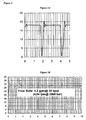
- the number of oil droplets in the first emulsion with a size >1.2 ⁇ m may be 5 x 10 11 /ml or less, as described below.
- Oil droplets with a size >1.2 ⁇ m are disadvantageous as they can cause instability of the emulsion due to agglomeration and coalescence of droplets [14].
- the first emulsion may then be subjected to at least one pass of microfluidization to form the second emulsion having a reduced average oil droplet size.
- the average oil droplet size of the second emulsion is 500 nm or less.
- the number of oil droplets in the second emulsion having a size >1.2 ⁇ m may be 5 x 10 10 /ml or less, as described below. To achieve these characteristics it may be necessary to pass the emulsion components through the microfluidization device a plurality of times, e.g . 2, 3, 4, 5, 6, 7 times.
- the second emulsion is filtered through a hydrophilic asymmetric membrane, e.g . a hydrophilic polyethersulfone membrane, to give an oil-in-water emulsion that may be suitable for use as a vaccine adjuvant.
- the average oil droplet size of the oil-in-water emulsion produced after filtration may be 220 nm or less, e.g . between 135-175 nm, between 145-165 nm, or about 155 nm.
- the number of oil droplets having a size >1.2 ⁇ m present in the oil-in-water emulsion produced after filtration may be 5 x 10 8 /ml or less, e.g . 5 x 10 7 /ml or less, 5 x 10 6 /ml or less, 2 x 10 6 /ml or less or 5 x 10 5 /ml or less.
- the final oil-in-water emulsion formed after filtration may have at least 10 2 times fewer oil droplets having a size >1.2 ⁇ m in comparison to the first emulsion, and ideally at least 10 3 times fewer ( e.g . 10 4 times fewer).
- step (i) and (ii) are used prior to step (iii).
- step (iii) may be used.
- the invention provides the use of a hydrophilic asymmetric membrane for preparing an oil-in-water emulsion adjuvant. Further features of the membrane and the emulsion adjuvant are discussed below.
- methods of the invention are performed between 20-60°C, and ideally at 40 ⁇ 5°C.
- first and second emulsion components may be relatively stable even at higher temperatures, thermal breakdown of some components can still occur and so lower temperatures are preferred.
- the average oil droplet size (i.e . the number average diameter of the emulsion's oil droplets) may be measured using a dynamic light scattering technique, as described in reference 13.
- a dynamic light scattering measurement machine is the Nicomp 380 Submicron Particle Size Analyzer (from Particle Sizing Systems).
- the number of particles having a size > 1.2 ⁇ m may be measured using a particle counter such as the AccusizerTM 770 (from Particle Sizing Systems).
- Methods of the invention are used for the manufacture of oil-in-water emulsions.
- These emulsions include three core ingredients: an oil; an aqueous component; and a surfactant.
- the oil will typically be biodegradable (metabolisable) and biocompatible.
- Squalene is particularly preferred for use in the present invention.
- the oil of the present invention may comprise a mixture (or combination) of oils e.g. comprising squalene and at least one further oil.
- an emulsion can comprise oil(s) including those from, for example, an animal (such as fish) or a vegetable source.
- Sources for vegetable oils include nuts, seeds and grains. Peanut oil, soybean oil, coconut oil, and olive oil, the most commonly available, exemplify the nut oils.
- Jojoba oil can be used e.g. obtained from the jojoba bean. Seed oils include safflower oil, cottonseed oil, sunflower seed oil, sesame seed oil and the like. In the grain group, corn oil is the most readily available, but the oil of other cereal grains such as wheat, oats, rye, rice, teff, triticale and the like may also be used.
- 6-10 carbon fatty acid esters of glycerol and 1,2-propanediol may be prepared by hydrolysis, separation and esterification of the appropriate materials starting from the nut and seed oils. Fats and oils from mammalian milk are metabolizable and so may be used. The procedures for separation, purification, saponification and other means necessary for obtaining pure oils from animal sources are well known in the art.
- cod liver oil cod liver oil
- shark liver oils and whale oil such as spermaceti exemplify several of the fish oils which may be used herein.
- a number of branched chain oils are synthesized biochemically in 5-carbon isoprene units and are generally referred to as terpenoids.
- Squalane the saturated analog to squalene
- Fish oils, including squalene and squalane, are readily available from commercial sources or may be obtained by methods known in the art.
- the tocopherols can take several forms e.g . different salts and/or isomers. Salts include organic salts, such as succinate, acetate, nicotinate, etc . If a salt of this tocopherol is to be used, the preferred salt is the succinate.
- An oil combination comprising squalene and a tocopherol e.g . DL- ⁇ -tocopherol
- a tocopherol e.g . DL- ⁇ -tocopherol
- the aqueous component can be plain water (e.g . w.f.i.) or can include further components e.g . solutes. For instance, it may include salts to form a buffer e.g . citrate or phosphate salts, such as sodium salts.
- Typical buffers include: a phosphate buffer; a Tris buffer; a borate buffer; a succinate buffer; a histidine buffer; or a citrate buffer. Buffers will typically be included in the 5-20mM range.
- the surfactant is preferably biodegradable (metabolisable) and biocompatible.
- Surfactants can be classified by their 'HLB' (hydrophile/lipophile balance), where a HLB in the range 1-10 generally means that the surfactant is more soluble in oil than in water, and a HLB in the range 10-20 are more soluble in water than in oil.
- Emulsions preferably comprise at least one surfactant that has a HLB of at least 10 e.g . at least 15, or preferably at least 16.
- the invention can be used with surfactants including, but not limited to: the polyoxyethylene sorbitan esters surfactants (commonly referred to as the Tweens), especially polysorbate 20 and polysorbate 80; copolymers of ethylene oxide (EO), propylene oxide (PO), and/or butylene oxide (BO), sold under the DOWFAXTM tradename, such as linear EO/PO block copolymers; octoxynols, which can vary in the number of repeating ethoxy (oxy-1,2-ethanediyl) groups, with octoxynol-9 (Triton X-100, or t-octylphenoxypolyethoxyethanol) being of particular interest; (octylphenoxy)polyethoxyethanol (IGEPAL CA-630/NP-40); phospholipids such as phosphatidylcholine (lecithin); polyoxyethylene fatty ethers derived from lauryl, cetyl, steary
- surfactants can be included in the emulsion e.g . Tween 80/Span 85 mixtures, or Tween 80/Triton-X100 mixtures.
- a combination of a polyoxyethylene sorbitan ester such as polyoxyethylene sorbitan monooleate (Tween 80) and an octoxynol such as t-octylphenoxy-polyethoxyethanol (Triton X-100) is also suitable.
- Another useful combination comprises laureth 9 plus a polyoxyethylene sorbitan ester and/or an octoxynol.
- Useful mixtures can comprise a surfactant with a HLB value in the range of 10-20 (e.g . Tween 80, with a HLB of 15.0) and a surfactant with a HLB value in the range of 1-10 ( e.g . Span 85, with a HLB of 1.8).
- emulsion components may be mixed to form a first emulsion.
- Oil droplets in the first emulsion have an average size of 5000 nm or less e.g . 4000 nm or less, 3000nm or less, 2000nm or less, 1200nm or less, 1000nm or less, e.g . an average size between 800 and 1200 nm or between 300nm and 800nm.
- the number of oil droplets with a size > 1.2 ⁇ m may be 5 x 10 11 /ml or less, e.g. 5 x 10 10 /ml or less or 5 x 10 9 /ml or less.
- the first emulsion is then microfluidised to form a second emulsion having a lower average oil droplet size than the first emulsion.
- the average oil droplet size of the first emulsion can be achieved by mixing the first emulsion's components in a homogenizer. For instance, as shown in Figure 1 , they can be combined in a mixing vessel (12) and then the combined components can be introduced (13) into a mechanical homogenizer, such as a rotor-stator homogenizer (1).
- a mechanical homogenizer such as a rotor-stator homogenizer (1).
- Homogenizers can operate in a vertical and/or horizontal manner. For convenience in a commercial setting, in-line homogenizers are preferred.
- the components are introduced into a rotor-stator homogenizer and meet a rapidly rotating rotor containing slots or holes.
- the components are centrifugally thrown outwards in a pump like fashion and pass through the slots/holes.
- the homogenizer includes multiple combinations of rotors and stators e.g . a concentric arrangement of comb-teeth rings, as shown by features (3) & (4); (5) & (6) and (7) & (8) in Figure 1 and by Figure 2 .
- the rotors in useful large-scale homogenizers may have comb-teeth rings on the edge of a horizontally oriented multi-bladed impeller (e.g feature (9) in Figure 1 ) aligned in close tolerance to matching teeth in a static liner.
- the first emulsion forms via a combination of turbulence, cavitation and mechanical shearing occurring within the gap between rotor and stator.
- the components are usefully introduced in a direction parallel to the rotor's axis.
- An important performance parameter in rotor-stator homogenizers is the tip speed of the rotor (peripheral velocity). This parameter is a function both of rotation speed and of rotor diameter.
- a tip speed of at least 10 ms -1 is useful, and ideally quicker e.g. ⁇ 20 ms -1 , ⁇ 30 ms -1 , ⁇ 40 ms -1 , etc.
- a tip speed of 40 ms -1 can be readily achieved at 10,000 rpm with a small homogenizer or at lower rotation speeds ( e.g . 2,000 rpm) with a larger homogenizer. Suitable high-shear homogenizers are commercially available.
- the homogenizer should ideally have a flow rate of at least 300 L/hr e.g . ⁇ 400 L/hr, ⁇ 500 L/hr, ⁇ 600 L/hr, ⁇ 700 L/hr, ⁇ 800 L/hr, ⁇ 900 L/hr, ⁇ 1000 L/hr, ⁇ 2000 L/hr, ⁇ 5000 L/hr, or even ⁇ 10000 L/hr.
- Suitable high-capacity homogenizers are commercially available.
- a preferred homogenizer provides a shear rate of between 3x10 5 and 1x10 6 s -1 , e.g . between 3x10 5 and 7x10 5 s -1 , between 4x10 5 and 6x10 5 s -1 , e.g . about 5x10 5 s -1 .
- the homogenizer may be cooled during use. Ideally, the temperature of the first emulsion is maintained below 60°C during homogenization, e.g . below 45°C.
- the first emulsion components may be homogenized multiple times (e.g . 2, 3, 4, 5, 6, 7, 8, 9, 10, 20, 30, 40, 50 or more times).
- the emulsion components can instead be circulated (e.g . feature (11) in Figure 1 ).
- the first emulsion may be formed by circulating the first emulsion components through a homogenizer a plurality of times (e.g. 2, 3, 4, 5, 6, 7, 8, 9, 10, 20, 30, 40, 50, 100 etc times).
- too many cycles may be undesirable as it can produce re-coalescence as described in reference 14.
- the size of oil droplets may be monitored if homogenizer circulation is used to check that a desired droplet size is reached and/or that re-coalescence is not occurring.
- Circulation through the homogenizer is advantageous because it can reduce the average size of the oil droplets in the first emulsion. Circulation is also advantageous because it can reduce the number of oil droplets having a size >1.2 ⁇ m in the first emulsion. These reductions in average droplet size and number of droplets >1.2 ⁇ m in the first emulsion can provide advantages in downstream process(es).
- circulation of the first emulsion components through the homogenizer can lead to an improved microfluidization process which may then result in a reduced number of oil droplets having a size >1.2 ⁇ m in the second emulsion, i.e . after microfluidization.
- This improvement in the second emulsion parameters can provide improved filtration performance. Improved filtration performance may lead to less content losses during filtration, e.g . losses of squalene, Tween 80 and Span 85 when the oil-in-water emulsion is MF59.
- Type I circulation is illustrated in Figure 5
- type II circulation is illustrated in Figure 6 .
- the circulation of the first emulsion components may comprise a type I circulation of transferring the first emulsion components between a first premix container and a homogenizer.
- the first premix container may be from 50 to 500 L in size, e.g . 100 to 400 L, 100 to 300 L, 200 to 300 L, 250 L or 280 L.
- the first premix container may be manufactured from stainless steel.
- the type I circulation may be continued for 10 to 60 minutes, e.g . 10 to 40 minutes or 20 minutes.
- the circulation of the first emulsion components may comprise a type II circulation of transferring the first emulsion components from a first premix container, through a first homogenizer to a second premix container (optionally having the same properties as the first premix container), and then through a second homogenizer.
- the second homogenizer will usually be the same as the first homogenizer, but in some arrangements the first and second homogenizers are different.
- the first emulsion components may be transferred back to the first premix container, for example if the type II circulation process is to be repeated.
- the emulsion components may travel in a figure of eight route between the first and second premix containers via a single homogenizer (see Figure 6 ).
- Type II circulation may be carried out a single time or a plurality of times, e.g. 2, 3, 4, 5 etc. times.
- Type II circulation is advantageous, compared to type I circulation, because it can help to ensure that all of the components of the first emulsion pass through the homogenizer. Emptying of the first premix container means that the complete emulsion contents have passed through the homogenizer, into the second premix container. Similarly, the contents of the second premix container can be emptied, again ensuring that they all pass through the homogenizer.
- the type II arrangement can conveniently ensure that all of the emulsion components are homogenized at least twice, which can reduce both the average size of the oil droplets and the number of oil droplets having a size >1.2 ⁇ m in the first emulsion.
- An ideal type II circulation thus involves emptying the first premix container and passing substantially all of its contents through the homogenizer into the second premix container, followed by emptying the second premix container and re-passing substantially all of its contents through the homogenizer back into the first premix container.
- all particles pass through the homogenizer at least twice, whereas this is difficult to achieve with type I circulation.
- a combination of type I and type II circulations is used, and this combination can provide a first emulsion with good characteristics.
- this combination can greatly reduce of the number of oil droplets having a size > 1.2 ⁇ m in the first emulsion.
- This combination can comprise any order of type I and II circulation, e.g ., type I followed by type II, type II followed by type I, type I followed by type II followed by type I again etc.
- the combination comprises 20 minutes of type I circulation followed by a single type II circulation, i.e . transferring the circulated first emulsion components from a first premix container, through a first homogenizer to a second premix container, and then through a second homogenizer once.
- the first and second premix containers may be held under an inert gas, e.g . nitrogen, e.g . at up to 0.5 bar. This can prevent the emulsion components from oxidizing, which is particularly advantageous if one of the emulsion components is squalene. This can provide an increase in the stability of the emulsion.
- an inert gas e.g . nitrogen, e.g . at up to 0.5 bar.
- the initial input for the homogenizer may be a non-homogenized mixture of the first emulsion components.
- This mixture may be prepared by mixing the individual first emulsion components individually but, in some embodiments, multiple components can be combined prior to this mixing. For instance, if the emulsion includes a surfactant with a HLB below 10 then this surfactant may be combined with an oil prior to mixing. Similarly, if the emulsion includes a surfactant with a HLB above 10 then this surfactant may be combined with an aqueous component prior to mixing. Buffer salts may be combined with an aqueous component prior to mixing, or may be added separately.
- Methods of the invention may be used at large scale.
- a method may involve preparing a first emulsion whose volume is greater than 1 liter e.g . ⁇ 5 liters, ⁇ 10 liters, ⁇ 20 liters, ⁇ 50 liters, ⁇ 100 liters, ⁇ 250 liters, etc.
- the first emulsion may be microfluidized, or may be stored to await microfluidization.
- the input for the homogenizer will be the output of a microfluidizer, such that the first emulsion is microfluidized and then again subjected to homogenization.
- the first emulsion After its formation the first emulsion is microfluidized in order to reduce its average oil droplet size and/or to reduce the number of oil droplets having a size of >1.2 ⁇ m.
- Microfluidization instruments reduce average oil droplet size by propelling streams of input components through geometrically fixed channels at high pressure and high velocity.
- the pressure at the entrance to the interaction chamber (also called the "first pressure”) may be substantially constant (i.e. ⁇ 15%; e.g. ⁇ 10%, ⁇ 5%, ⁇ 2%) for at least 85% of the time during which components are fed into the microfluidizer, e.g . at least 87%, at least 90%, at least 95%, at least 99% or 100% of the time during which the emulsion is fed into the microfluidizer.
- the first pressure is 1300 bar ⁇ 15% (18 kPSI ⁇ 15%), i.e . between 1100 bar and 1500 bar (between 15 KIPSI and 21 kPSI) for 85% of the time during which the emulsion is fed into the microfluidizer.
- Two suitable pressure profiles are shown in Figure 3 .
- the pressure is substantially constant for at least 85% of the time, whereas in Figure 3B the pressure continuously remains substantially constant.
- a microfluidization apparatus typically comprises at least one intensifier pump (preferably two pumps, which may be synchronous) and an interaction chamber.
- the intensifier pump which is ideally electric-hydraulic driven, provides high pressure (i.e . the first pressure) to force an emulsion into and through the interaction chamber.
- the synchronous nature of the intensifier pumps may be used to provide the substantially constant pressure of the emulsion discussed above, which means that the emulsion droplets are all exposed to substantially the same level of shear forces during microfluidization.
- a further advantage of the use of a substantially constant pressure is that it can reduce fatigue failures in the microfluidization device, which may lead to longer life of the device.
- a further advantage of the use of a substantially constant pressure is that the parameters of the second emulsion can be improved.
- the number of oil droplets having a size >1.2 ⁇ m present in the second emulsion can be reduced.
- the average oil droplet size of the second emulsion can be reduced when a substantially constant pressure is used.
- the reduction in the average oil droplet size and in the number of oil droplets having a size >1.2 ⁇ m in the second emulsion may provide improved filtration performance. Improved filtration performance may lead to less content losses during filtration, e.g . losses of squalene, Tween 80 and Span 85 when the emulsion is MF59.
- the interaction chamber may contain a plurality, e.g . 2, 3, 4, 5, 6, 7, 8, 9, 10 etc, of fixed geometry channels into which the emulsion passes.
- the emulsion enters the interaction chamber through an input line which may have a diameter of between 200 to 250 ⁇ m.
- the emulsion divides into streams as it enters the interaction chamber and, under high pressure, accelerates to high velocity. As it passes through the channels, forces produced by the high pressure may act to reduce the emulsion's oil droplet size and reduce the number of oil droplets having a size >1.2 ⁇ m.
- the interaction chamber usually includes no moving parts. It may include ceramic (e.g . alumina) or diamond (e.g . polycrystalline diamond) channel surfaces. Other surfaces may be made of stainless steel.
- the fixed geometry of the plurality of channels in the interaction chamber may be "Y" type geometry or "Z" type geometry.
- a single input emulsion stream is split into first and second emulsion streams, which are then recombined into a single output emulsion stream.
- each of the first and second emulsion streams may independently be split into a first and second plurality ( e.g . 2, 3, 4, 5, 6, 7, 8, 9, 10 etc. ) of sub-streams.
- the first and second emulsion streams are ideally flowing in substantially opposite directions ( e.g .
- the first and second emulsion streams, or their sub-streams, are flowing in substantially the same plane ( ⁇ 20°) and the flow direction of the first emulsion stream is 180 ⁇ 20° different from the flow direction of the second emulsion stream).
- the forces produced when the emulsion streams are recombined may act to reduce the emulsion's oil droplet size and reduce the number of oil droplets having a size >1.2 ⁇ m.
- a Z-type geometry interaction chamber the emulsion stream passes around a plurality ( e.g . 2, 3, 4, 5, 6, 7, 8, 9, 10 etc ) of substantially right angled comers ( i.e . 90 ⁇ 20°).
- Figure 4 illustrates an interaction chamber with Z-type geometry and two right-angled comers in the direction of flow.
- an input emulsion stream may be split into a plurality ( e.g . 2, 3, 4, 5, 6, 7, 8, 9, 10 etc.) of sub-streams and then recombined into a single output emulsion stream (e.g . as shown in Figure 4 , with four sub-streams (32)).
- the split and then recombination (31) may occur at any point between input and output.
- the forces produced when the emulsion contacts the channel walls as it passes around the comers may act to reduce the emulsion's oil droplet size and reduce the number of oil droplets having a size >1.2 ⁇ m.
- An example of a Z-type interaction chamber is the E230Z interaction chamber from Microfluidics.
- the emulsion stream passes around two substantially right angled corners. At the point when the input emulsion stream passes around the first substantially right angled corner, it is split into five sub-streams. At the point when the sub-streams pass around the second substantially right angled corner, they are recombined into a single output emulsion stream.
- a preferred microfluidization apparatus operates at a pressure between 170 bar and 2750 bar (approximately 2500 psi to 40000 psi) e.g . at about 345 bar, about 690 bar, about 1380 bar, about 2070 bar, etc.
- a preferred microfluidization apparatus operates at a flow rate of up to 20 L/min e.g . up to 14 L/min, up to 7 L/min, up to 3.5 L/min, etc.
- a preferred microfluidization apparatus has an interaction chamber that provides a shear rate in excess of 1x10 6 s -1 e.g . ⁇ 2.5x10 6 s -1 , ⁇ 5x10 6 s -1 , ⁇ 10 7 s -1 , etc .
- a microfluidization apparatus can include multiple interaction chambers that are used in parallel e.g . 2, 3, 4, 5 or more, but it is more useful to include a single interaction chamber.
- the microfluidization device may comprise an auxiliary processing module (APM) comprising at least one channel.
- APM auxiliary processing module
- the APM contributes to the reduction in the average size of the oil droplets in the emulsion being passed through the microfluidization device, although the majority of the reduction occurs in the interaction chamber.
- the emulsion components are introduced to the interaction chamber by the intensifier pump(s) under a first pressure.
- the emulsion components generally exit the APM at a second pressure which is lower than the first pressure (e.g . atmospheric pressure). In general, between 80 and 95% of the pressure difference between the first and the second pressures is dropped across the interaction chamber ( e.g .
- the interaction chamber may provide approximately 90% of the pressure drop while the APM may provide approximately 10% of the pressure drop. If the pressure dropped across the interaction chamber and the pressure dropped across the auxiliary processing module do not account for the whole of the pressure difference between the first and the second pressure, this can be due to a finite pressure drop across the connectors between the interaction chamber and the auxiliary processing module.
- the APM usually includes no moving parts. It may include ceramic (e.g . alumina) or diamond (e.g . polycrystalline diamond) channel surfaces. Other surfaces may be made of stainless steel.
- the APM is generally positioned downstream of the interaction chamber and may also be positioned sequential to the interaction chamber.
- APMs are generally positioned downstream of interaction chambers comprising Y-type channels to suppress cavitation and thereby increase the flowrate in the Y-type chamber by up to 30%.
- APMs are generally positioned upstream of interaction chambers comprising Z-type channels to reduce the size of large agglomerates. In the latter case, the APM only decreases the flowrate in the Z-type chambers by up to 3%.
- APM downstream of an interaction chamber comprising a plurality of Z-type channels is advantageous in the present invention because it can lead to a greater reduction in average oil droplet size and a greater reduction in the number of oil droplets having a size of >1.2 ⁇ m present in the second emulsion.
- the reduction in number of oil droplets having a size > 1.2 ⁇ m in the second emulsion may provide improved filtration performance.
- Improved filtration performance may lead to less content losses during filtration, e.g . losses of squalene, Tween 80 and Span 85 when the oil-in-water emulsion is MF59.
- a further advantage of this positioning of a Z-type interaction chamber and a downstream APM is that it can lead to a slower pressure decrease after the interaction chamber. The slower pressure decrease may lead to an increase in product stability because there is less gas enclosed in the emulsion.
- An APM contains at least one fixed geometry channel into which the emulsion passes.
- the APM may contain a plurality e.g. 2, 3, 4, 5, 6, 7, 8, 9, 10 etc, of fixed geometry channels into which the emulsion passes.
- the channel or channels of the APM may be linear or non-linear. Suitable non-linear channels are of "Z" type geometry or "Y" type geometry, which are the same as those described above for the interaction chamber.
- the channel, or channels, of the APM are of Z-type geometry.
- a plurality of Z-type channels divides the emulsion into streams as it enters the APM.
- an APM comprising a plurality of fixed geometry channels is advantageous compared to a single fixed geometry channel APM because it can lead to a greater reduction in the number of oil droplets having a size >1.2 ⁇ m present in the second emulsion.
- the reduction in the number of oil droplets having a size > 1.2 ⁇ m in the second emulsion can provide improved filtration performance. Improved filtration performance may lead to less content losses during filtration, e.g. losses of squalene, Tween 80 and Span 85 when the oil-in-water emulsion is MF59.
- a microfluidization apparatus generates heat during operation, which can raise an emulsion's temperature by 15-20°C relative to the first emulsion.
- the microfluidized emulsion is cooled as soon as possible.
- the temperature of the second emulsion may be maintained below 60°C, e.g . below 45°C.
- an interaction chamber's output and/or an APM's output may feed into a cooling mechanism, such as a heat exchanger or cooling coil.
- the distance between the output and the cooling mechanism should be kept as short as possible to shorten the overall time by reducing cooling delays. In one embodiment, the distance between the output of the microfluidizer and the cooling mechanism is between 20-30cm.
- a cooling mechanism is particularly useful when an emulsion is subjected to multiple microfluidization steps, to prevent over-heating of the emulsion.
- the result of microfluidization is an oil-in-water emulsion, the second emulsion, in which the average size of the oil droplets is 500 nm or less.
- This average size is particularly useful as it facilitates filter sterilization of the emulsion.
- Emulsions in which at least 80% by number of the oil droplets have an average size of 500 nm or less, e.g . 400 nm or less, 300 nm of less, 200 nm or less or 165 nm or less, are particularly useful.
- the number of oil droplets in the second emulsion having a size >1.2 ⁇ m is 5 x 10 10 /ml or less, e.g . 5 x 10 9 /ml or less, 5 x 10 8 /ml or less or 2 x 10 8 /ml or less.
- the initial input for the microfluidization may be the first emulsion.
- the microfluidized emulsion is subjected to microfluidization again, such that multiple rounds of microfluidization occur.
- the second emulsion may be formed by circulating the second emulsion components through a microfluidization device a plurality of times, e.g . 2, 3, 4, 5, 6, 7, 8, 9, 10 etc times.
- the second emulsion may be formed by circulating the second emulsion components through a microfluidization device 4 to 7 times.
- the circulation of the second emulsion components may comprise a type I circulation of transferring the second emulsion components between a first emulsion container (optionally having the same properties as the first premix container) and the microfluidization device.
- the circulation of the second emulsion components may comprise a type II circulation of transferring the second emulsion components from a first emulsion container, through a first microfluidization device to a second emulsion container (optionally having the same properties as the first premix container), and then through a second microfluidization device.
- the second microfluidization device may be the same as the first microfluidization device. Alternatively, the second microfluidization device may be different to the first microfluidization device.
- the first emulsion container may be the same as the first premix container. Alternatively, the first emulsion container may be the same as the second premix container.
- the second emulsion container may be the same as the first premix container. Alternatively, the second emulsion container may be the same as the second premix container.
- the first emulsion container may be the same as the first premix container and the second emulsion container may be the same as the second premix container.
- the first emulsion container may be the same as the second premix container and the second emulsion container may be the same as the first premix container.
- first and second emulsion containers may be different to the first and second premix containers.
- the second emulsion components may be transferred back to the first emulsion container, for example if the type II circulation process is to be repeated.
- Type II circulation may be carried out a single time or a plurality of times, e.g . 2, 3, 4, 5 etc times.
- Type II circulation is advantageous as it ensures that all the second emulsion components have passed through the microfluidization device at least 2 times, which reduces the average size of the oil droplets and the number of oil droplets having a size >1.2 ⁇ m in the second emulsion.
- a combination of type I circulation and type II circulation may be used during microfluidization.
- This combination can comprise any order of type I and II circulation, e.g ., type I followed by type II, type II followed by type I, type I followed by type II followed by type I again etc.
- the first and second emulsion containers may be held under an inert gas, e.g . up to 0.5 bar of nitrogen. This prevents the emulsion components oxidizing, which is particularly advantageous if one of the emulsion components is squalene. This leads to an increase in the stability of the emulsion.
- an inert gas e.g . up to 0.5 bar of nitrogen.
- Methods of the invention may be used at large scale.
- a method may involve microfluidizing a volume greater than 1 liter e.g . ⁇ 5 liters, ⁇ 10 liters, ⁇ 20 liters, ⁇ 50 liters, ⁇ 100 liters, ⁇ 250 liters, etc .
- the second emulsion is filtered. This filtration removes any large oil droplets that have survived the homogenization and microfluidization procedures. Although small in number terms, these oil droplets can be large in volume terms and they can act as nucleation sites for aggregation, leading to emulsion degradation during storage. Moreover, this filtration step can achieve filter sterilization.
- the particular filtration membrane suitable for filter sterilization depends on the fluid characteristics of the second emulsion and the degree of filtration required.
- a filter's characteristics can affect its suitability for filtration of the microfluidized emulsion. For example, its pore size and surface characteristics can be important, particularly when filtering a squalene-based emulsion.
- the pore size of membranes used with the invention should permit passage of the desired droplets while retaining the unwanted droplets. For example, it should retain droplets that have a size of ⁇ 1 ⁇ m while permitting passage of droplets ⁇ 200nm.
- a 0.2 ⁇ m or 0.22 ⁇ m filter is ideal, and can also achieve filter sterilization.
- the emulsion may be prefiltered e.g . through a 0.45 ⁇ m filter.
- the prefiltration and filtration can be achieved in one step by the use of known double-layer filters that include a first membrane layer with larger pores and a second membrane layer with smaller pores. Double-layer filters are particularly useful with the invention.
- the first layer ideally has a pore size >0.3 ⁇ m, such as between 0.3-2 ⁇ m or between 0.3-1 ⁇ m, or between 0.4-0.8 ⁇ m, or between 0.5-0.7 ⁇ m.
- a pore size of ⁇ 0.75 ⁇ m in the first layer is preferred.
- the first layer may have a pore size of 0.6 ⁇ m or 0.45 ⁇ m, for example.
- the second layer ideally has a pore size which is less than 75% of (and ideally less than half of) the first layer's pore size, such as between 25-70% or between 25-49% of the first layer's pore size e.g. between 30-45%, such as 1/3 or 4/9, of the first layer's pore size.
- the second layer may have a pore size ⁇ 0.3 ⁇ m, such as between 0.15-0.28 ⁇ m or between 0.18-0.24 ⁇ m e.g . a 0.2 ⁇ m or 0.22 ⁇ m pore size second layer.
- the first membrane layer with larger pores provides a 0.45 ⁇ m filter
- the second membrane layer with smaller pores provides a 0.22 ⁇ m filter.
- the filtration membrane is asymmetric.
- the prefiltration membrane may be asymmetric.
- An asymmetric membrane is one in which the pore size varies from one side of the membrane to the other e.g . in which the pore size is larger at the entrance face than at the exit face.
- One side of the asymmetric membrane may be referred to as the "coarse pored surface", while the other side of the asymmetric membrane may be referred to as the "fine pored surface”.
- a double-layer filter one or (ideally) both layers may be asymmetric.
- the filtration membrane may be porous or homogeneous.
- a homogeneous membrane is usually a dense film ranging from 10 to 200 ⁇ m.
- a porous membrane has a porous structure.
- the filtration membrane is porous.
- both layers may be porous, both layers may be homogenous, or there may be one porous and one homogenous layer.
- a preferred double-layer filter is one in which both layers are porous.
- the second emulsion is prefiltered through an asymmetric, hydrophilic porous membrane and then filtered through another asymmetric hydrophilic porous membrane having smaller pores than the prefiltration membrane. This can use a double-layer filter.
- the filter membrane(s) may be autoclaved prior to use to ensure that it is sterile.
- Filtration membranes are typically made of polymeric support materials such as PTFE (poly-tetra-fluoro-ethylene), PES (polyethersulfone), PVP (polyvinyl pyrrolidone), PVDF (polyvinylidene fluoride), nylons (polyamides), PP (polypropylene), celluloses (including cellulose esters), PEEK (polyetheretherketone), nitrocellulose, etc . (although the invention preferably avoids the use of cellulose-based filters).
- These support materials have varying characteristics, with some supports being intrinsically hydrophobic (e.g . PTFE) and others being intrinsically hydrophilic (e.g . cellulose acetates).
- these intrinsic characteristics can be modified by treating the membrane surface.
- the two membranes can be made of different materials or (ideally) of the same material.
- An ideal filter for use with the invention has a hydrophilic surface, in contrast to the teaching of references 9-12 that hydrophobic (polysulfone) filters should be used.
- Filters with hydrophilic surfaces can be formed from hydrophilic materials, or by hydrophilization of hydrophobic materials, and a preferred filter for use with the invention is a hydrophilic polyethersulfone membrane.
- Several different methods are known to transform hydrophobic PES membranes into hydrophilic PES membranes. Often it is achieved by coating the membrane with a hydrophilic polymer. To provide permanent attachment of the hydrophilic polymer to the PES a hydrophilic coating layer is usually subjected either to a cross-linking reaction or to grafting.
- Reference 15 discloses a process for modifying the surface properties of a hydrophobic polymer having functionalizable chain ends, comprising contacting the polymer with a solution of a linker moiety to form a covalent link, and then contacting the reacted hydrophobic polymer with a solution of a modifying agent.
- Reference 16 discloses a method of PES membrane hydrophilization by direct membrane coating, involving pre-wetting with alcohol, and then soaking in an aqueous solution containing a hydrophilic monomer, a polyfunctional monomer (cross-linker) and a polymerization initiator.
- references 17 and 18 disclose coating a PES membrane by soaking it in an aqueous solution of hydrophilic polymer (polyalkylene oxide) and at least one polyfunctional monomer (cross-linker), and then polymerizing a monomer to provide a non-extractable hydrophilic coating.
- Reference 19 describes the hydrophilization of PES membrane by a grafting reaction in which a PES membrane is submitted to low-temperature helium plasma treatment followed by grafting of hydrophilic monomer N-vinyl-2-pyrrolidone (NVP) onto the membrane surface. Further such processes are disclosed in references 20 to 26.
- references 27 to 33 disclose a method of preparing a hydrophilic charge-modified membrane that has low membrane extractables and allows fast recovery of ultrapure water resistivity, having a cross-linked inter-penetrating polymer network structure formed making a polymer solution of a blend of PES, PVP, polyethyleneimine, and aliphatic diglycidyl ether, forming a thin film of the solution, and precipitating the film as a membrane.
- reference 34 discloses a method of preparing a hydrophilic charge-modified membrane that has low membrane extractables and allows fast recovery of ultrapure water resistivity, having a cross-linked inter-penetrating polymer network structure formed making a polymer solution of a blend of PES, PVP, polyethyleneimine, and aliphatic diglycidyl ether, forming a thin film of the solution, and precipitating the film as a membrane.
- Hybrid approaches can be used, in which hydrophilic additives are present during membrane formation and are also added later as a coating e.g . see reference 35.
- Hydrophilization of PES membrane can also be achieved by treatment with low temperature plasmas.
- Reference 36 describes hydrophilic modification of PES membrane by treatment with low temperature CO 2 -plasma.
- Hydrophilization of PES membrane can also be achieved by oxidation, as described in reference 37. This method involves pre-wetting a hydrophobic PES membrane in a liquid having a low surface tension, exposing the wet PES membrane to an aqueous solution of oxidizer, and then heating.
- Phase inversion can also be used, as described in reference 38.
- An ideal hydrophilic PES membrane can be obtained by treatment of PES (hydrophobic) with PVP (hydrophilic). Treatment with PEG (hydrophilic) instead of PVP has been found to give a hydrophilized PES membrane that is easily fouled (particularly when using a squalene-containing emulsion) and also disadvantageously releases formaldehyde during autoclaving.
- a preferred double-layer filter has a first hydrophilic PES membrane and a second hydrophilic PES membrane.
- Embodiments are not preferred (and might sometimes be disclaimed) in which filtration is first via a double-layer cellulose acetate filter and then through a second double-layer cellulose acetate filter, where the smaller pore size of the first filter is larger than the larger pore size of the second filter, and where the second double-layer filter achieves filter sterilization.
- Known hydrophilic membranes include Bioassure (from Cuno); EverLUXTM polyethersulfone; STyLUXTM polyethersulfone (both from Meissner); Millex GV, Millex HP, Millipak 60, Millipak 200 and Durapore CVGL01TP3 membranes (from Millipore); FluorodyneTM EX EDF Membrane, SuporTM EAV; SuporTM EBV, SuporTM EKV (all from Pall); SartoporeTM (from Sartorius); Sterlitech's hydrophilic PES membrane; and Wolftechnik's WFPES PES membrane.
- the emulsion may be maintained at a temperature of 40°C or less, e.g . 30°C or less, to facilitate successful sterile filtration. Some emulsions may not pass through a sterile filter when they are at a temperature of greater than 40°C.
- Methods of the invention may be used at large scale.
- a method may involve filtering a volume greater than 1 liter e.g. ⁇ 5 liters, ⁇ 10 liters, ⁇ 20 liters, ⁇ 50 liters, ⁇ 100 liters, ⁇ 250 liters, etc.
- the result of microfluidization and filtration is an oil-in-water emulsion in which the average size of the oil droplets may be less than 220 nm, e.g . 155 ⁇ 20 nm, 155 ⁇ 10 nm or 155 ⁇ 5 nm, and in which the number of oil droplets having a size >1.2 ⁇ m may be 5 x 10 8 /ml or less, e.g . 5 x 10 7 /ml or less, 5 x 10 6 /ml or less, 2 x 10 6 /ml or less or 5 x 10 5 /ml or less.
- the average oil droplet size of emulsions described herein is generally not less than 50 nm.
- Methods of the invention may be used at large scale.
- a method may involve preparing a final emulsion with a volume greater than 1 liter e.g . ⁇ 5 liters, ⁇ 10 liters, ⁇ 20 liters, ⁇ 50 liters, ⁇ 100 liters, ⁇ 250 liters, etc.
- the oil-in-water emulsion may be transferred into sterile glass bottles.
- the glass bottles may be 5 L, 8 L, or 10 L in size.
- the oil-in-water may be transferred into a sterile flexible bag (flex bag).
- the flex bag may be 50 L, 100 L or 250 L in size.
- the flex bag may be fitted with one or more sterile connectors to connect the flex bag to the system.
- the use of a flex bag with a sterile connectors is advantageous compared to glass bottles because the flex bag is larger then the glass bottles meaning that it may not be necessary to change the flex bag to store all the emulsion manufactured in a single batch.
- Preferred amounts of oil (% by volume) in the final emulsion are between 2-20% e.g . about 10%.
- a squalene content of about 5% or about 10% is particularly useful.
- a squalene content (w/v) of between 30-50mg/ml is useful e.g. between 35-45mg/ml, 36-42mg/ml, 38-40mg/ml, etc .
- Preferred amounts of surfactants (% by weight) in the final emulsion are: polyoxyethylene sorbitan esters (such as Tween 80) 0.02 to 2%, in particular about 0.5% or about 1%; sorbitan esters (such as Span 85) 0.02 to 2%, in particular about 0.5% or about 1%; octyl- or nonylphenoxy polyoxyethanols (such as Triton X-100) 0.001 to 0.1%, in particular 0.005 to 0.02%; polyoxyethylene ethers (such as laureth 9) 0.1 to 20%, preferably 0.1 to 10% and in particular 0.1 to 1% or about 0.5%.
- polyoxyethylene sorbitan esters such as Tween 80 0.02 to 2%, in particular about 0.5% or about 1%
- sorbitan esters such as Span 85
- octyl- or nonylphenoxy polyoxyethanols such as Triton X-100
- polyoxyethylene ethers such as laureth 9)
- a polysorbate 80 content (w/v) of between 4-6mg/ml is useful e.g . between 4.1-5.3mg/ml.
- a sorbitan trioleate content (w/v) of between 4-6mg/ml is useful e.g . between 4.1-5.3mg/ml.
- the process is particularly useful for preparing any of the following oil-in-water emulsions:
- compositions of these emulsions may be modified by dilution or concentration (e.g . by an integer, such as 2 or 3 or by a fraction, such as 2/3 or 3/4), in which their ratios stay the same.
- concentration e.g . by an integer, such as 2 or 3 or by a fraction, such as 2/3 or 3/4
- Concentrated forms can be diluted ( e.g. with an antigen solution) to give a desired final concentration of emulsion.
- Emulsions of the invention are ideally stored at between 2°C and 8°C. They should not be frozen. They should ideally be kept out of direct light. In particular, squalene-containing emulsions and vaccines of the invention should be protected to avoid photochemical breakdown of squalene. If emulsions of the invention are stored then this is preferably in an inert atmosphere e.g. N 2 or argon.
- an inert atmosphere e.g. N 2 or argon.
- oil-in-water emulsion adjuvants on their own to patients (e.g. to provide an adjuvant effect for an antigen that has been separately administered to the patient), it is more usual to admix the adjuvant with an antigen prior to administration, to form an immunogenic composition e.g. a vaccine.
- an immunogenic composition e.g. a vaccine.
- Mixing of emulsion and antigen may take place extemporaneously, at the time of use, or can take place during vaccine manufacture, prior to filling.
- the methods of the invention can be applied in both situations.
- a method of the invention may include a further process step of admixing the emulsion with an antigen component.
- it may include a further step of packaging the adjuvant into a kit as a kit component together with an antigen component.
- the invention can be used when preparing mixed vaccines or when preparing kits including antigen and adjuvant ready for mixing.
- the volumes of bulk antigen and emulsion that are mixed will typically be greater than 1 liter e.g. ⁇ 5 liters, ⁇ 10 liters, ⁇ 20 liters, ⁇ 50 liters, ⁇ 100 liters, ⁇ 250 liters, etc.
- the volumes that are mixed will typically be smaller than 1 milliliter e.g. 0.6ml, ⁇ 0.5ml, ⁇ 0.4ml, ⁇ 0.3ml, ⁇ 0.2ml, etc.
- substantially equal volumes of emulsion and antigen solution i.e. substantially 1:1 ( e.g. between 1.1:1 and 1:1.1, preferably between 1.05:1 and 1:1.05, and more preferably between 1.025:1 and 1:1.025).
- an excess of emulsion or an excess of antigen may be used [42]. Where an excess volume of one component is used, the excess will generally be at least 1.5:1 e.g. ⁇ 2:1, ⁇ 2.5:1, ⁇ 3:1, ⁇ 4:1, ⁇ 5:1, etc.
- antigen and adjuvant are presented as separate components within a kit, they are physically separate from each other within the kit, and this separation can be achieved in various ways.
- the components may be in separate containers, such as vials.
- the contents of two vials can then be mixed when needed e.g. by removing the contents of one vial and adding them to the other vial, or by separately removing the contents of both vials and mixing them in a third container.
- one of the kit components is in a syringe and the other is in a container such as a vial.
- the syringe can be used ( e.g. with a needle) to insert its contents into the vial for mixing, and the mixture can then be withdrawn into the syringe.
- the mixed contents of the syringe can then be administered to a patient, typically through a new sterile needle. Packing one component in a syringe eliminates the need for using a separate syringe for patient administration.
- the two kit components are held together but separately in the same syringe e.g. a dual-chamber syringe, such as those disclosed in references 43-50 etc.
- a dual-chamber syringe such as those disclosed in references 43-50 etc.
- kits components will generally all be in liquid form.
- a component typically the antigen component rather than the emulsion component
- the other component is in liquid form.
- the two components can be mixed in order to reactivate the dry component and give a liquid composition for administration to a patient.
- a lyophilized component will typically be located within a vial rather than a syringe.
- Dried components may include stabilizers such as lactose, sucrose or mannitol, as well as mixtures thereof e.g. lactose/sucrose mixtures, sucrose/mannitol mixtures, etc .
- One possible arrangement uses a liquid emulsion component in a pre-filled syringe and a lyophilized antigen component in a vial.
- vaccines contain components in addition to emulsion and antigen then these further components may be included in one these two kit components, or may be part of a third kit component.
- Suitable containers for mixed vaccines of the invention, or for individual kit components include vials and disposable syringes. These containers should be sterile.
- the vial is preferably made of a glass or plastic material.
- the vial is preferably sterilized before the composition is added to it.
- vials are preferably sealed with a latex-free stopper, and the absence of latex in all packaging material is preferred.
- a vial has a butyl rubber stopper.
- the vial may include a single dose of vaccine/component, or it may include more than one dose (a 'multidose' vial) e.g. 10 doses.
- a vial includes 10 x 0.25 ml doses of emulsion.
- Preferred vials are made of colorless glass.
- a vial can have a cap (e.g. a Luer lock) adapted such that a pre-filled syringe can be inserted into the cap, the contents of the syringe can be expelled into the vial ( e.g. to reconstitute lyophilized material therein), and the contents of the vial can be removed back into the syringe.
- a needle can then be attached and the composition can be administered to a patient.
- the cap is preferably located inside a seal or cover, such that the seal or cover has to be removed before the cap can be accessed.
- the syringe will not normally have a needle attached to it, although a separate needle may be supplied with the syringe for assembly and use.
- Safety needles are preferred.
- 1-inch 23-gauge, 1-inch 25-gauge and 5/8-inch 25-gauge needles are typical.
- Syringes may be provided with peel-off labels on which the lot number, influenza season and expiration date of the contents may be printed, to facilitate record keeping.
- the plunger in the syringe preferably has a stopper to prevent the plunger from being accidentally removed during aspiration.
- the syringes may have a latex rubber cap and/or plunger.
- Disposable syringes contain a single dose of vaccine.
- the syringe will generally have a tip cap to seal the tip prior to attachment of a needle, and the tip cap is preferably made of a butyl rubber. If the syringe and needle are packaged separately then the needle is preferably fitted with a butyl rubber shield.
- the emulsion may be diluted with a buffer prior to packaging into a vial or a syringe.
- Typical buffers include: a phosphate buffer; a Tris buffer; a borate buffer; a succinate buffer; a histidine buffer; or a citrate buffer. Dilution can reduce the concentration of the adjuvant's components while retaining their relative proportions e.g. to provide a "half-strength" adjuvant.
- Containers may be marked to show a half-dose volume e.g. to facilitate delivery to children.
- a syringe containing a 0.5ml dose may have a mark showing a 0.25ml volume.
- a glass container e.g. a syringe or a vial
- a container made from a borosilicate glass rather than from a soda lime glass.
- antigens can be used with oil-in-water emulsions, including but not limited to: viral antigens, such as viral surface proteins; bacterial antigens, such as protein and/or saccharide antigens; fungal antigens; parasite antigens; and tumor antigens.
- the invention is particularly useful for vaccines against influenza virus, HIV, hookworm, hepatitis B virus, herpes simplex virus, rabies, respiratory syncytial virus, cytomegalovirus, Staphylococcus aureus, chlamydia, SARS coronavirus, varicella zoster virus, Streptococcus pneumoniae, Neisseria meningitidis, Mycobacterium tuberculosis, Bacillus anthracis, Epstein Barr virus, human papillomavirus, etc.
- influenza virus HIV, hookworm, hepatitis B virus, herpes simplex virus, rabies, respiratory syncytial virus, cytomegalovirus, Staphylococcus aureus, chlamydia, SARS coronavirus, varicella zoster virus, Streptococcus pneumoniae, Neisseria meningitidis, Mycobacterium tuberculosis, Bacillus anthrac
- a solution of the antigen will normally be mixed with the emulsion e.g . at a 1:1 volume ratio. This mixing can either be performed by a vaccine manufacturer, prior to filling, or can be performed at the point of use, by a healthcare worker.
- compositions made using the methods of the invention are pharmaceutically acceptable. They may include components in addition to the emulsion and the optional antigen.
- the composition may include a preservative such as thiomersal or 2-phenoxyethanol. It is preferred, however, that the vaccine should be substantially free from ( i.e. less than 5 ⁇ g/ml) mercurial material e.g. thiomersal-free [75,76]. Vaccines and components containing no mercury are more preferred.
- the pH of a composition will generally be between 5.0 and 8.1, and more typically between 6.0 and 8.0 e.g. between 6.5 and 7.5.
- a process of the invention may therefore include a step of adjusting the pH of the vaccine prior to packaging.
- the composition is preferably sterile.
- the composition is preferably non-pyrogenic e.g. containing ⁇ 1 EU (endotoxin unit, a standard measure) per dose, and preferably ⁇ 0.1 EU per dose.
- the composition is preferably gluten free.
- the composition may include material for a single immunization, or may include material for multiple immunizations (i.e . a 'multidose' kit).
- a preservative is preferred in multidose arrangements.
- Vaccines are typically administered in a dosage volume of about 0.5ml, although a half dose (i.e. about 0.25ml) may be administered to children.
- the invention provides kits and compositions prepared using the methods of the invention.
- the compositions prepared according to the methods of the invention are suitable for administration to human patients, and the invention provides a method of raising an immune response in a patient, comprising the step of administering such a composition to the patient.
- kits and compositions for use as medicaments are also described.
- the immune response raised by these methods and uses will generally include an antibody response, preferably a protective antibody response.
- compositions can be administered in various ways.
- the most preferred immunization route is by intramuscular injection (e.g. into the arm or leg), but other available routes include subcutaneous injection, intranasal [77-79], oral [80], intradermal [81,82], transcutaneous, transdermal [83], etc.
- Vaccines prepared according to the invention may be used to treat both children and adults.
- the patient may be less than 1 year old, 1-5 years old, 5-15 years old, 15-55 years old, or at least 55 years old.
- the patient may be elderly ( e.g. ⁇ 50 years old, preferably ⁇ 65 years), the young ( e.g. ⁇ 5 years old), hospitalized patients, healthcare workers, armed service and military personnel, pregnant women, the chronically ill, immunodeficient patients, and people travelling abroad.
- the vaccines are not suitable solely for these groups, however, and may be used more generally in a population.
- Vaccines of the invention may be administered to patients at substantially the same time as ( e.g. during the same medical consultation or visit to a healthcare professional) other vaccines.
- the first emulsion has the characteristics described above.
- a second emulsion i.e. a microfluidized emulsion.
- the microfluidised emulsion has the characteristics described above.
- the invention also provides a method for the manufacture of a vaccine, comprising combining an emulsion with an antigen, where the emulsion has the characteristics described above.
- composition comprising X may consist exclusively of X or may include something additional e.g. X + Y.
- a process comprising a step of mixing two or more components does not require any specific order of mixing.
- components can be mixed in any order. Where there are three components then two components can be combined with each other, and then the combination may be combined with the third component, etc.
- animal (and particularly bovine) materials are used in the culture of cells, they should be obtained from sources that are free from transmissible spongiform encaphalopathies (TSEs), and in particular free from bovine spongiform encephalopathy (BSE). Overall, it is preferred to culture cells in the total absence of animal-derived materials.
- TSEs transmissible spongiform encaphalopathies
- BSE bovine spongiform encephalopathy
- a microfluidized emulsion comprising squalene, polysorbate 80, sorbitan trioleate and sodium citrate buffer was prepared according to the present invention.
- the emulsion was microfluidized until it had an average oil droplet size of 165 nm or less and a number of oil droplets having a size >1.2 ⁇ m of 5 x 10 8 /ml or less.
- the emulsion was filtered through a sterilizing grade filter cartridge (filter A) having a prefilter membrane of hydrophilic asymmetric porous polyethersulfone having a pore size of 0.45 ⁇ m and an endfilter membrane of hydrophilic asymmetric porous polyethersulfone having a pore size of 0.2 ⁇ m.
- filter A sterilizing grade filter cartridge
- the emulsion was maintained at a temperature of 40 ⁇ 5°C.
- filter A consistently reduced the average size of the oil droplets in the emulsion. Furthermore, filter A consistently reduced the number of oil droplets having a size > 1.2. ⁇ m in the emulsion by approximately 10 3 fold.
- filter B had a prefilter membrane of hydrophilic asymmetric porous polyethersulfone and an endfilter membrane of hydrophilic asymmetric porous polyethersulfone having a pore size of 0.2 ⁇ m.
- the emulsion was maintained at a temperature of 40 ⁇ 5°C. This process was carried out for four separate runs and the characteristics of the filtered emulsions were measured and are shown in Table 2.
- filter B consistently reduced the average size of the oil droplets in the emulsion. Furthermore, filter B consistently reduced the number of oil droplets having a size > 1.2 ⁇ m in the emulsion by approximately 10 3 fold.
- filter B results in a slightly lower oil droplet size but a slightly greater number of oil droplets having a size greater than 1.2 ⁇ m. However, both filters A and B showed excellent results.
- filter C The same microfluidized emulsion as used for example 1 was filtered through another different sterilizing grade filter cartridge (filter C).
- Filter C had a prefilter membrane of hydrophilic asymmetric porous polyethersulfone having a pore size of 0.45 ⁇ m and an endfilter membrane of hydrophilic asymmetric porous polyethersulfone having a pore size of 0.2 ⁇ m.
- the emulsion was maintained at a temperature of 40 ⁇ 5°C.
- filter D had a prefilter membrane of hydrophilic asymmetric porous polyethersulfone and an endfilter membrane of hydrophilic porous PVDF. During filtration, the emulsion was maintained at a temperature of 40 ⁇ 5°C.
- Filter C showed excellent filtration results providing a filtered emulsion having an average oil droplet size of 155 ⁇ 20 nm and a number of oil droplets having a size >1.2 ⁇ m of 5 x 10 6 /ml or less.
- filter D also provided a filtered emulsion meeting the above criteria, it was found to block more quickly, thus necessitating the replacement of the filter D membrane.
- all polyethersulfone filters were superior to this PVDF filter.
- the yield of emulsion after filtration of 50 liters of emulsion was measured to determine if the filters were suitable for industrial-scale use.
- the % of input emulsion which was recovered after filtration was as follows: Table 3 1 2 3 4 5 6 7 8 9 10 % 50 16 8 8 8 13 4 82 88 89
- a low recovery % indicates that the filter retains the emulsion, for instance because of blocking. It is clear that only filters 1, 8, 9 and 10 (i.e. filters A, B & C from above, plus one further filter which is similar to filter A but has a larger pore size in the first layer) gave yields of ⁇ 50%, and that the yields that are most practicable for using at an industrial scale are filters 8-10.
- Filters 1, 8, 9 and 10 are all double-layer hydrophilic PES membranes, prepared by three different manufacturers. The first layers in these four membranes are either 0.45 ⁇ m or 0.6 ⁇ m and the second layer is 0.2 ⁇ m. The best results were seen when at least one of the two layers was an asymmetric membrane.
Claims (18)
- Méthode de fabrication d'un adjuvant de vaccin en émulsion huile-dans-eau contenant du squalène, comprenant les étapes :(i) de formation d'une première émulsion ayant une taille moyenne de gouttelettes d'huile de 5000 nm ou moins ;(ii) de micro-fluidisation de la première émulsion afin de former une deuxième émulsion ayant une taille moyenne de gouttelettes d'huile de 500 nm ou moins ; et(iii) de filtration de la deuxième émulsion à l'aide d'une membrane asymétrique hydrophile, fournissant ainsi un adjuvant de vaccin.
- Méthode selon la revendication 1, dans laquelle la membrane hydrophile est une membrane de polyéthersulfone hydrophile.
- Méthode selon l'une quelconque des revendications précédentes, dans laquelle le nombre de gouttelettes d'huile ayant une taille >1,2 µm dans la première émulsion est de 5×10¹¹/ml ou moins, dans un mode de réalisation de 5×10¹⁰/ml ou moins, dans un mode de réalisation de 5×10⁸/ml ou moins.
- Méthode selon l'une quelconque des revendications précédentes, dans laquelle la taille moyenne de gouttelettes d'huile après filtration est inférieure à 220 nm.
- Méthode selon l'une quelconque des revendications précédentes, dans laquelle la deuxième émulsion est pré-filtrée à travers une membrane préalablement à la filtration.
- Méthode selon la revendication 5, dans laquelle les étapes de pré-filtration et de filtration sont effectuées à l'aide d'un filtre à double couche.
- Méthode selon la revendication 5 ou la revendication 6, dans laquelle la membrane de pré-filtration est asymétrique et/ou poreuse.
- Méthode selon l'une quelconque des revendications précédentes, dans laquelle la membrane de filtration est poreuse.
- Méthode selon l'une quelconque des revendications précédentes, dans laquelle la membrane de filtration, et éventuellement la membrane de pré-filtration, comprend un matériau de support polymère.
- Méthode selon l'une quelconque des revendications précédentes, dans laquelle (i) la première couche possède une taille de pores ≥0,3 µm, et/ou (ii) la deuxième couche possède une taille de pores <0,3 µm.
- Méthode de préparation d'une composition de vaccin, comprenant la préparation d'un adjuvant en émulsion selon l'une quelconque des revendications 1 à 10, et la combinaison de l'adjuvant en émulsion avec un antigène.
- Méthode de préparation d'un kit de vaccin, comprenant la préparation d'un adjuvant en émulsion selon l'une quelconque des revendications 1 à 10, et le conditionnement en un kit de l'adjuvant en émulsion comme composant de kit conjointement avec un composant d'antigène.
- Méthode selon la revendication 12, dans laquelle les composants de kit se trouvent dans des flacons séparés.
- Méthode selon la revendication 13, dans laquelle les flacons sont faits en verre borosilicaté.
- Méthode selon l'une quelconque des revendications 11 à 14, dans laquelle l'adjuvant en émulsion est un adjuvant en vrac, et la méthode comprend l'extraction de doses unitaires à partir de l'adjuvant en vrac pour conditionnement sous forme de composants de kit.
- Méthode selon l'une quelconque des revendications 11 à 15, dans laquelle l'antigène est un antigène d'influenzavirus.
- Méthode selon la revendication 16, dans laquelle la combinaison de l'émulsion et de l'antigène forme une composition de vaccin et dans laquelle la composition de vaccin comporte environ 15 µg, environ 10 µg, environ 7,5 µg, environ 5 µg, environ 3,8 µg, environ 3,75 µg, environ 1,9 µg, ou environ 1,5 µg d'hémagglutinine par souche d'influenzavirus.
- Méthode selon la revendication 16 ou la revendication 17, dans laquelle la combinaison de l'émulsion et de l'antigène forme une composition de vaccin et dans laquelle la composition de vaccin comporte un conservateur à base de thiomersal ou de 2-phénoxyéthanol.
Priority Applications (2)
| Application Number | Priority Date | Filing Date | Title |
|---|---|---|---|
| SI201030614T SI2506832T1 (sl) | 2009-12-03 | 2010-12-03 | Hidrofilna filtracija med izdelavo adjuvantov za cepiva |
| EP13157613.4A EP2601933B1 (fr) | 2009-12-03 | 2010-12-03 | Filtration hydrophile pendant la fabrication d'adjuvants de vaccins |
Applications Claiming Priority (2)
| Application Number | Priority Date | Filing Date | Title |
|---|---|---|---|
| US28351709P | 2009-12-03 | 2009-12-03 | |
| PCT/IB2010/003273 WO2011067669A2 (fr) | 2009-12-03 | 2010-12-03 | Filtration hydrophile pendant la fabrication d'adjuvants de vaccins |
Related Child Applications (2)
| Application Number | Title | Priority Date | Filing Date |
|---|---|---|---|
| EP13157613.4A Division-Into EP2601933B1 (fr) | 2009-12-03 | 2010-12-03 | Filtration hydrophile pendant la fabrication d'adjuvants de vaccins |
| EP13157613.4A Division EP2601933B1 (fr) | 2009-12-03 | 2010-12-03 | Filtration hydrophile pendant la fabrication d'adjuvants de vaccins |
Publications (2)
| Publication Number | Publication Date |
|---|---|
| EP2506832A2 EP2506832A2 (fr) | 2012-10-10 |
| EP2506832B1 true EP2506832B1 (fr) | 2014-02-26 |
Family
ID=43971135
Family Applications (3)
| Application Number | Title | Priority Date | Filing Date |
|---|---|---|---|
| EP13157613.4A Revoked EP2601933B1 (fr) | 2009-12-03 | 2010-12-03 | Filtration hydrophile pendant la fabrication d'adjuvants de vaccins |
| EP10807661.3A Revoked EP2506832B1 (fr) | 2009-12-03 | 2010-12-03 | Filtration hydrophile pendant la fabrication d'adjuvants de vaccins |
| EP10252044.2A Revoked EP2343052B1 (fr) | 2009-12-03 | 2010-12-03 | Filtration hydrophile pendant la fabrication d'adjuvants de vaccins |
Family Applications Before (1)
| Application Number | Title | Priority Date | Filing Date |
|---|---|---|---|
| EP13157613.4A Revoked EP2601933B1 (fr) | 2009-12-03 | 2010-12-03 | Filtration hydrophile pendant la fabrication d'adjuvants de vaccins |
Family Applications After (1)
| Application Number | Title | Priority Date | Filing Date |
|---|---|---|---|
| EP10252044.2A Revoked EP2343052B1 (fr) | 2009-12-03 | 2010-12-03 | Filtration hydrophile pendant la fabrication d'adjuvants de vaccins |
Country Status (22)
| Country | Link |
|---|---|
| US (3) | US10213383B2 (fr) |
| EP (3) | EP2601933B1 (fr) |
| JP (2) | JP5754860B2 (fr) |
| KR (2) | KR101616735B1 (fr) |
| CN (2) | CN104688687A (fr) |
| AU (1) | AU2010325748B2 (fr) |
| BR (1) | BR112012013425A2 (fr) |
| CA (1) | CA2780425C (fr) |
| CL (1) | CL2012001268A1 (fr) |
| DK (1) | DK2343052T3 (fr) |
| EA (1) | EA025622B1 (fr) |
| ES (3) | ES2558056T3 (fr) |
| HK (2) | HK1159995A1 (fr) |
| HR (1) | HRP20130623T1 (fr) |
| IL (1) | IL219627B (fr) |
| MX (1) | MX2012005598A (fr) |
| NZ (1) | NZ599881A (fr) |
| PL (1) | PL2343052T3 (fr) |
| PT (1) | PT2343052E (fr) |
| SG (1) | SG10201501612RA (fr) |
| SI (2) | SI2506832T1 (fr) |
| WO (1) | WO2011067669A2 (fr) |
Cited By (1)
| Publication number | Priority date | Publication date | Assignee | Title |
|---|---|---|---|---|
| EP2601933B1 (fr) | 2009-12-03 | 2015-10-07 | Novartis AG | Filtration hydrophile pendant la fabrication d'adjuvants de vaccins |
Families Citing this family (18)
| Publication number | Priority date | Publication date | Assignee | Title |
|---|---|---|---|---|
| EP2638895B1 (fr) | 2009-12-03 | 2024-03-20 | Seqirus UK Limited | Circulation de composants pendant l'homogénéisation des émulsions |
| DE102009056884B4 (de) | 2009-12-03 | 2021-03-18 | Novartis Ag | Impfstoff-Adjuvantien und verbesserte Verfahren zur Herstellung derselben |
| CL2012001399A1 (es) | 2009-12-03 | 2013-03-08 | Novartis Ag | Metodo para fabricar adyuvante para vacuna (emulsion aceite/agua con escualeno, polisorbato 80 y trioleato de sorbitan), que comprende (i) formar primera emulsion en homogenizador desde un contendor a otro para formar segunda emulsion, (ii) y microfluidizar primera emulsion para formar segunda emulsion. |
| RS52565B (en) † | 2009-12-03 | 2013-04-30 | Novartis Ag | METHOD OF INTERACTION AND REVERSE PRESSURE FOR MICROFLUIDIZATION |
| WO2011141819A1 (fr) | 2010-05-12 | 2011-11-17 | Novartis Ag | Procédés améliorés d'élaboration de squalène |
| GB201009676D0 (en) * | 2010-06-10 | 2010-07-21 | Glaxosmithkline Biolog Sa | Novel process |
| EP2692853A4 (fr) * | 2011-03-30 | 2014-12-03 | Nat Ct Geriatrics & Gerontology | Dispositif de culture de type séparation sur membrane, kit de culture de type séparation sur membrane, procédé de séparation de cellules souches les employant et membrane de séparation |
| RU2014140521A (ru) | 2012-03-08 | 2016-04-27 | Новартис Аг | Адъювантные составы бустерных вакцин |
| EP2892553A1 (fr) | 2012-09-06 | 2015-07-15 | Novartis AG | Vaccins combinatoires avec méningococcus de sérogroupe b et d/t/p |
| RU2015111987A (ru) | 2012-10-12 | 2016-12-10 | Глаксосмитклайн Байолоджикалс Са | Несшитые бесклеточные коклюшные антигены для применения в комбинированных вакцинах |
| CA2894260A1 (fr) | 2012-12-18 | 2014-06-26 | Glaxosmithkline Biologicals S.A. | Conjugues de protection contre la diphterie et/ou le tetanos |
| DK3197487T3 (da) | 2014-09-26 | 2022-09-05 | Seqirus Uk Ltd | Vaccination af immunsvækkede individer |
| JP2017528511A (ja) | 2014-09-26 | 2017-09-28 | セキラス ユーケー リミテッド | 免疫低下された被験体のワクチン接種 |
| EP3511020B1 (fr) | 2014-12-02 | 2021-01-20 | Novartis AG | Fabrication de compositions contenant des tensioactifs |
| JP6995756B2 (ja) * | 2015-12-23 | 2022-02-04 | ノバルティス アーゲー | レチノイン酸を含む水中油型エマルジョン |
| CA3127639A1 (fr) * | 2019-01-30 | 2020-08-06 | Glaxosmithkline Biologicals Sa | Melanges huile/tensioactif pour auto-emulsification |
| CN116171166A (zh) * | 2020-06-30 | 2023-05-26 | 塞其里斯英国有限公司 | 水包油乳液佐剂的冷过滤 |
| CN113876943A (zh) * | 2020-07-03 | 2022-01-04 | 神州细胞工程有限公司 | 浓缩的水包油型亚微乳佐剂及其制备方法 |
Family Cites Families (82)
| Publication number | Priority date | Publication date | Assignee | Title |
|---|---|---|---|---|
| US4060082A (en) | 1976-08-16 | 1977-11-29 | Mpl, Inc. | Dual-ingredient medication dispenser |
| US4340482A (en) | 1978-02-21 | 1982-07-20 | Millipore Corporation | Process for grafting amino acid molecules onto preformed polymer surfaces and products prepared thereby |
| US4198183A (en) | 1978-11-01 | 1980-04-15 | Claus Kowitz | Motion translation apparatus |
| US4673504A (en) | 1980-10-27 | 1987-06-16 | Cuno Inc. | Charge modified microporous membrane |
| US4473474A (en) | 1980-10-27 | 1984-09-25 | Amf Inc. | Charge modified microporous membrane, process for charge modifying said membrane and process for filtration of fluid |
| US4533254A (en) | 1981-04-17 | 1985-08-06 | Biotechnology Development Corporation | Apparatus for forming emulsions |
| US4473475A (en) | 1981-05-29 | 1984-09-25 | Amf Inc. | Charge modified microporous membrane, process for charge modifying said membrane, and process for filtration of fluids |
| US4432875A (en) | 1981-05-29 | 1984-02-21 | Brunswick Corporation | Semi-permeable membranes and processes for making the same |
| US4413074A (en) | 1982-01-25 | 1983-11-01 | Brunswick Corporation | Hydrophilic surfaces and process for making the same |
| NZ209308A (en) | 1983-08-30 | 1991-08-27 | Genentech Inc | Vaccine against hsv involving a truncated membrane-free derivative of a membrane-bound protein |
| US4705753A (en) | 1984-06-08 | 1987-11-10 | Gregor Harry P | Biologically active acrylonitrile-based copolymeric membrane |
| US4618533A (en) | 1984-11-30 | 1986-10-21 | Millipore Corporation | Porous membrane having hydrophilic surface and process |
| US4794002A (en) | 1985-11-01 | 1988-12-27 | Monsanto Company | Modified polymeric surfaces and process for preparing same |
| US4964990A (en) | 1987-05-20 | 1990-10-23 | Gelman Sciences, Inc. | Filtration membranes and method of making the same |
| US4943374A (en) | 1988-04-21 | 1990-07-24 | Gessner & Co., Gmbh | Use of a microporous membrane constructed of polyether sulfon and hydrophilization agent for the filtration of beer |
| DE68928907T2 (de) | 1988-10-17 | 1999-09-16 | Hemasure | Verfahren zur kovalenten oberflächen-modifikation hydrophober polymere und erzeugnisse daraus |
| WO1990014837A1 (fr) | 1989-05-25 | 1990-12-13 | Chiron Corporation | Composition d'adjuvant comprenant une emulsion de gouttelettes d'huile d'une taille inferieure au micron |
| JPH06500128A (ja) | 1991-05-08 | 1994-01-06 | シュバイツ・ゼルム―・ウント・インプフィンスティテュート・ベルン | 免疫刺激及び免疫増強性再構成インフルエンザウイロソーム及びそれを含有するワクチン |
| JPH0614756Y2 (ja) | 1991-06-26 | 1994-04-20 | 株式会社アルテ | 組み立て式の2室式容器兼用注射器 |
| US5178765A (en) | 1991-09-18 | 1993-01-12 | Gelman Sciences Inc. | Hydrophilic membranes prepared from polyethersulfone/poly-2-oxazoline/polyvinylpyrrolidone blend |
| EP0656779B1 (fr) | 1992-08-28 | 2000-04-12 | Pharmos Corporation | Emulsion sous-micronique comme vehicule pour l'administration oculaire d'un medicament |
| US5531893A (en) | 1993-02-12 | 1996-07-02 | Gelman Sciences Inc. | Inter-penetrating network charge modified microporous membrane |
| US5277812A (en) | 1993-02-12 | 1994-01-11 | Gelman Sciences Inc. | Inter-penetrating network charge modified microporous membrane |
| US6645463B1 (en) | 1994-05-16 | 2003-11-11 | The Board Of Regents Of The University Of Michigan | Blood-pool selective carrier for lipophilic imaging agents |
| WO1995035157A1 (fr) | 1994-06-20 | 1995-12-28 | Nippon Shinyaku Co., Ltd. | Procede de fabrication d'emulsion et emulsificateur |
| US5487965A (en) | 1994-09-06 | 1996-01-30 | Xerox Corporation | Processes for the preparation of developer compositions |
| US5496284A (en) | 1994-09-27 | 1996-03-05 | Waldenburg; Ottfried | Dual-chamber syringe & method |
| US5510118A (en) | 1995-02-14 | 1996-04-23 | Nanosystems Llc | Process for preparing therapeutic compositions containing nanoparticles |
| DE19542499A1 (de) | 1995-11-15 | 1997-05-22 | Bayer Ag | Verfahren und Vorrichtung zur Herstellung einer parenteralen Arzneistoffzubereitung |
| DE19612966B4 (de) | 1996-04-01 | 2009-12-10 | Novartis Vaccines And Diagnostics Gmbh & Co. Kg | MDCK-Zellen und Verfahren zur Vermehrung von Influenzaviren |
| WO1998001174A1 (fr) | 1996-07-05 | 1998-01-15 | Debiotech S.A. | Seringue a chambre double permettant le melange de deux produits avant leur injection |
| US6168718B1 (en) | 1996-11-08 | 2001-01-02 | Pall Corporation | Method for purifying blood plasma and apparatus suitable therefor |
| CA2271846A1 (fr) | 1996-11-12 | 1998-05-22 | Dean T. Tsou | Membrane polymere et hydrophile d'inversion de phase |
| US5971953A (en) | 1998-01-09 | 1999-10-26 | Bachynsky; Nicholas | Dual chamber syringe apparatus |
| WO1999017820A1 (fr) | 1997-10-03 | 1999-04-15 | Texas Pharmaceuticals, Inc. | Seringue amelioree a double compartiment |
| US6039872A (en) | 1997-10-27 | 2000-03-21 | Pall Corporation | Hydrophilic membrane |
| WO1999050189A1 (fr) | 1998-03-30 | 1999-10-07 | Ebara Corporation | Procede et dispositif de traitement des eaux riches en manganese |
| GB9808689D0 (en) | 1998-04-23 | 1998-06-24 | Kalsep Ltd | Improved membrane |
| DE19835749C1 (de) | 1998-08-07 | 2000-02-03 | Dieter Perthes | Fertig-Spritze für nicht-stabile Arzneimittel |
| JP3995830B2 (ja) | 1999-01-13 | 2007-10-24 | 富士フイルム株式会社 | 熱現像画像記録材料 |
| US6193077B1 (en) | 1999-02-08 | 2001-02-27 | Osmonics, Inc. | Non-cracking hydrophilic polyethersulfone membranes |
| CA2689696C (fr) | 1999-02-26 | 2013-08-06 | Novartis Vaccines And Diagnostics, Inc. | Microemulsions a macromolecules et microparticules adsorbees |
| GB9923176D0 (en) | 1999-09-30 | 1999-12-01 | Smithkline Beecham Biolog | Novel composition |
| DE10059430A1 (de) | 2000-11-30 | 2002-06-06 | Cognis Deutschland Gmbh | Feinteilige Emulsionen |
| MY134424A (en) | 2001-05-30 | 2007-12-31 | Saechsisches Serumwerk | Stable influenza virus preparations with low or no amount of thiomersal |
| WO2003063911A1 (fr) * | 2002-02-01 | 2003-08-07 | Anges Mg, Inc. | Compositions pharmaceutiques contenant un leurre et procede d'utilisation |
| US20060148776A1 (en) * | 2003-03-13 | 2006-07-06 | Conforma Therapeutics Corporation | Drug formulations having long and medium chain triglycerides |
| US20040185068A1 (en) | 2003-03-18 | 2004-09-23 | Zhi-Jian Yu | Self-emulsifying compositions, methods of use and preparation |
| JP2006522090A (ja) | 2003-04-04 | 2006-09-28 | ファイザー・プロダクツ・インク | マイクロ流動化された水中油形エマルジョン及びワクチン組成物 |
| WO2005027872A2 (fr) | 2003-06-04 | 2005-03-31 | Nanobio Corporation | Compositions pour l'inactivation de micro-organismes pathogenes, procedes de fabrication de compositions, et leurs procedes d'utilisation |
| US20050208083A1 (en) | 2003-06-04 | 2005-09-22 | Nanobio Corporation | Compositions for inactivating pathogenic microorganisms, methods of making the compositons, and methods of use thereof |
| KR101153898B1 (ko) | 2004-03-23 | 2012-06-18 | 니프로 가부시키가이샤 | 프리필드 시린지 |
| RU2412686C2 (ru) | 2004-03-23 | 2011-02-27 | Новартис Аг | Фармацевтические композиции |
| KR20070008625A (ko) | 2004-04-05 | 2007-01-17 | 화이자 프로덕츠 인코포레이티드 | 미세유체화된 수중유 유화액 및 백신 조성물 |
| GB0411411D0 (en) | 2004-05-21 | 2004-06-23 | Glaxosmithkline Biolog Sa | Vaccines |
| GB0416120D0 (en) * | 2004-07-19 | 2004-08-18 | Health Prot Agency | Stable compositions containing OMV's |
| AU2005295777A1 (en) * | 2004-10-13 | 2006-04-27 | 3M Innovative Properties Company | Method for preparing hydrophilic polyethersulfone membrane |
| CA2586074C (fr) | 2004-11-09 | 2013-07-23 | Novagali Pharma Sa | Emulsion ophtalmique du type huile dans eau a potentiel zeta positif stable |
| GB0427568D0 (en) | 2004-12-16 | 2005-01-19 | Resolution Chemicals Ltd | Particle-size reduction apparatus, and the use thereof |
| CA2601022C (fr) * | 2005-03-23 | 2023-03-07 | Glaxosmithkline Biologicals S.A. | Utilisation d'un virus de la grippe et d'un adjuvant de type emulsion huile dans l'eau pour induire une cellule t cd-4 et/ou ameliorer la reponse de la cellule a memoire b |
| US8703095B2 (en) | 2005-07-07 | 2014-04-22 | Sanofi Pasteur S.A. | Immuno-adjuvant emulsion |
| WO2008051186A2 (fr) | 2005-08-09 | 2008-05-02 | Nanobio Corporation | Compositions de nano-émulsion ayant une activité anti-inflammatoire |
| ES2761937T3 (es) | 2005-10-24 | 2020-05-21 | Magsense Life Sciences Inc | Método para preparar micropartículas recubiertas con polímero |
| AU2006310163B2 (en) | 2005-11-04 | 2011-09-15 | Seqirus UK Limited | Influenza vaccine with reduced amount of oil-in-water emulsion as adjuvant |
| FR2896162B1 (fr) | 2006-01-13 | 2008-02-15 | Sanofi Pasteur Sa | Emulsion huile dans eau thermoreversible |
| ES2619160T7 (es) * | 2006-01-27 | 2020-07-29 | Seqirus Uk Ltd | Vacunas contra la gripe que contienen hemaglutinina y proteínas de la matriz |
| WO2007098186A2 (fr) | 2006-02-22 | 2007-08-30 | Novavax, Inc. | Compositions d'adjuvant et de vaccin |
| EP1849452A1 (fr) | 2006-04-27 | 2007-10-31 | Cognis IP Management GmbH | Dispersions contenant acylglutamate |
| CN105727276A (zh) * | 2006-07-17 | 2016-07-06 | 葛兰素史密丝克莱恩生物有限公司 | 流感疫苗 |
| GB0622282D0 (en) | 2006-11-08 | 2006-12-20 | Novartis Ag | Quality control methods |
| EA200900784A1 (ru) | 2006-12-06 | 2009-12-30 | Новартис Аг | Вакцины, включающие антиген из четырех штаммов вируса гриппа |
| US20080187546A1 (en) * | 2006-12-15 | 2008-08-07 | Wasmoen Terri L | Method for Replicating Influenza Virus in Culture |
| CN102046011A (zh) * | 2008-04-04 | 2011-05-04 | 罗伯特·绍尔 | 微管相互作用剂的脂质-油-水纳米乳递送系统 |
| US8187554B2 (en) | 2008-04-23 | 2012-05-29 | Microfluidics International Corporation | Apparatus and methods for nanoparticle generation and process intensification of transport and reaction systems |
| TW201006517A (en) * | 2008-05-22 | 2010-02-16 | Asahi Kasei Medical Co Ltd | Filtration method |
| EP2307021A4 (fr) | 2008-06-19 | 2011-08-10 | Neurosystec Corp | Formulations |
| DE102009056884B4 (de) | 2009-12-03 | 2021-03-18 | Novartis Ag | Impfstoff-Adjuvantien und verbesserte Verfahren zur Herstellung derselben |
| DE102009056871A1 (de) | 2009-12-03 | 2011-06-22 | Novartis AG, 4056 | Impfstoff-Adjuvantien und verbesserte Verfahren zur Herstellung derselben |
| EP2601933B1 (fr) | 2009-12-03 | 2015-10-07 | Novartis AG | Filtration hydrophile pendant la fabrication d'adjuvants de vaccins |
| RS52565B (en) | 2009-12-03 | 2013-04-30 | Novartis Ag | METHOD OF INTERACTION AND REVERSE PRESSURE FOR MICROFLUIDIZATION |
| EP2638895B1 (fr) | 2009-12-03 | 2024-03-20 | Seqirus UK Limited | Circulation de composants pendant l'homogénéisation des émulsions |
| GB201009671D0 (en) | 2010-06-10 | 2010-07-21 | Glaxosmithkline Biolog Sa | Novel process |
-
2010
- 2010-12-03 EP EP13157613.4A patent/EP2601933B1/fr not_active Revoked
- 2010-12-03 AU AU2010325748A patent/AU2010325748B2/en active Active
- 2010-12-03 CN CN201510144280.8A patent/CN104688687A/zh active Pending
- 2010-12-03 WO PCT/IB2010/003273 patent/WO2011067669A2/fr active Application Filing
- 2010-12-03 EP EP10807661.3A patent/EP2506832B1/fr not_active Revoked
- 2010-12-03 PT PT102520442T patent/PT2343052E/pt unknown
- 2010-12-03 MX MX2012005598A patent/MX2012005598A/es active IP Right Grant
- 2010-12-03 JP JP2012541594A patent/JP5754860B2/ja active Active
- 2010-12-03 CA CA2780425A patent/CA2780425C/fr active Active
- 2010-12-03 SI SI201030614T patent/SI2506832T1/sl unknown
- 2010-12-03 KR KR1020127012098A patent/KR101616735B1/ko active IP Right Grant
- 2010-12-03 US US13/508,986 patent/US10213383B2/en active Active
- 2010-12-03 DK DK10252044.2T patent/DK2343052T3/da active
- 2010-12-03 ES ES13157613.4T patent/ES2558056T3/es active Active
- 2010-12-03 SG SG10201501612RA patent/SG10201501612RA/en unknown
- 2010-12-03 ES ES10807661.3T patent/ES2461852T3/es active Active
- 2010-12-03 EP EP10252044.2A patent/EP2343052B1/fr not_active Revoked
- 2010-12-03 KR KR1020157008289A patent/KR101625623B1/ko active IP Right Grant
- 2010-12-03 BR BR112012013425-6A patent/BR112012013425A2/pt not_active Application Discontinuation
- 2010-12-03 CN CN201080056000.3A patent/CN102858322B/zh active Active
- 2010-12-03 PL PL10252044T patent/PL2343052T3/pl unknown
- 2010-12-03 EA EA201270519A patent/EA025622B1/ru not_active IP Right Cessation
- 2010-12-03 SI SI201031055T patent/SI2601933T1/sl unknown
- 2010-12-03 ES ES10252044T patent/ES2426969T3/es active Active
- 2010-12-03 NZ NZ599881A patent/NZ599881A/en unknown
-
2012
- 2012-01-13 HK HK12100448.4A patent/HK1159995A1/xx not_active IP Right Cessation
- 2012-05-07 IL IL219627A patent/IL219627B/en active IP Right Grant
- 2012-05-15 CL CL2012001268A patent/CL2012001268A1/es unknown
-
2013
- 2013-03-06 HK HK13102772.5A patent/HK1175407A1/xx not_active IP Right Cessation
- 2013-07-03 HR HRP20130623AT patent/HRP20130623T1/hr unknown
-
2015
- 2015-03-03 JP JP2015040914A patent/JP2015098499A/ja active Pending
-
2019
- 2019-01-03 US US16/238,625 patent/US10799454B2/en active Active
-
2020
- 2020-09-09 US US17/015,550 patent/US20210077395A1/en not_active Abandoned
Cited By (1)
| Publication number | Priority date | Publication date | Assignee | Title |
|---|---|---|---|---|
| EP2601933B1 (fr) | 2009-12-03 | 2015-10-07 | Novartis AG | Filtration hydrophile pendant la fabrication d'adjuvants de vaccins |
Also Published As
Similar Documents
| Publication | Publication Date | Title |
|---|---|---|
| US10799454B2 (en) | Hydrophilic filtration during manufacture of vaccine adjuvants | |
| US9700616B2 (en) | Arranging interaction and back pressure chambers for microfluidization | |
| EP2506833B1 (fr) | Chambres d'interaction d'agencement et de contre-pression pour la microfluidisation | |
| EP2356983B1 (fr) | Circulation de composants pendant l'homogénéisation d'émulsions | |
| US8678184B2 (en) | Methods for producing vaccine adjuvants | |
| US8871816B2 (en) | Methods for producing vaccine adjuvants | |
| USRE46906E1 (en) | Methods for producing vaccine adjuvants | |
| AU2013202690B2 (en) | Hydrophilic filtration during manufacture of vaccine adjuvants | |
| AU2013213678B2 (en) | Arranging interaction and back pressure chambers for microfluidization |
Legal Events
| Date | Code | Title | Description |
|---|---|---|---|
| PUAI | Public reference made under article 153(3) epc to a published international application that has entered the european phase |
Free format text: ORIGINAL CODE: 0009012 |
|
| 17P | Request for examination filed |
Effective date: 20120703 |
|
| AK | Designated contracting states |
Kind code of ref document: A2 Designated state(s): AL AT BE BG CH CY CZ DE DK EE ES FI FR GB GR HR HU IE IS IT LI LT LU LV MC MK MT NL NO PL PT RO RS SE SI SK SM TR |
|
| DAX | Request for extension of the european patent (deleted) | ||
| REG | Reference to a national code |
Ref country code: HK Ref legal event code: DE Ref document number: 1175407 Country of ref document: HK |
|
| GRAP | Despatch of communication of intention to grant a patent |
Free format text: ORIGINAL CODE: EPIDOSNIGR1 |
|
| INTG | Intention to grant announced |
Effective date: 20130828 |
|
| RIN1 | Information on inventor provided before grant (corrected) |
Inventor name: KRAUS, GOTTFRIED Inventor name: ESKES, ROBERT |
|
| GRAS | Grant fee paid |
Free format text: ORIGINAL CODE: EPIDOSNIGR3 |
|
| GRAA | (expected) grant |
Free format text: ORIGINAL CODE: 0009210 |
|
| AK | Designated contracting states |
Kind code of ref document: B1 Designated state(s): AL AT BE BG CH CY CZ DE DK EE ES FI FR GB GR HR HU IE IS IT LI LT LU LV MC MK MT NL NO PL PT RO RS SE SI SK SM TR |
|
| REG | Reference to a national code |
Ref country code: GB Ref legal event code: FG4D |
|
| REG | Reference to a national code |
Ref country code: CH Ref legal event code: EP Ref country code: CH Ref legal event code: NV Representative=s name: E. BLUM AND CO. AG PATENT- UND MARKENANWAELTE , CH |
|
| REG | Reference to a national code |
Ref country code: AT Ref legal event code: REF Ref document number: 653133 Country of ref document: AT Kind code of ref document: T Effective date: 20140315 |
|
| REG | Reference to a national code |
Ref country code: RO Ref legal event code: EPE |
|
| REG | Reference to a national code |
Ref country code: SE Ref legal event code: TRGR |
|
| REG | Reference to a national code |
Ref country code: IE Ref legal event code: FG4D |
|
| REG | Reference to a national code |
Ref country code: DE Ref legal event code: R096 Ref document number: 602010013853 Country of ref document: DE Effective date: 20140410 |
|
| REG | Reference to a national code |
Ref country code: NL Ref legal event code: T3 |
|
| REG | Reference to a national code |
Ref country code: ES Ref legal event code: FG2A Ref document number: 2461852 Country of ref document: ES Kind code of ref document: T3 Effective date: 20140521 |
|
| REG | Reference to a national code |
Ref country code: LT Ref legal event code: MG4D |
|
| PG25 | Lapsed in a contracting state [announced via postgrant information from national office to epo] |
Ref country code: LT Free format text: LAPSE BECAUSE OF FAILURE TO SUBMIT A TRANSLATION OF THE DESCRIPTION OR TO PAY THE FEE WITHIN THE PRESCRIBED TIME-LIMIT Effective date: 20140226 Ref country code: NO Free format text: LAPSE BECAUSE OF FAILURE TO SUBMIT A TRANSLATION OF THE DESCRIPTION OR TO PAY THE FEE WITHIN THE PRESCRIBED TIME-LIMIT Effective date: 20140526 Ref country code: IS Free format text: LAPSE BECAUSE OF FAILURE TO SUBMIT A TRANSLATION OF THE DESCRIPTION OR TO PAY THE FEE WITHIN THE PRESCRIBED TIME-LIMIT Effective date: 20140626 |
|
| PG25 | Lapsed in a contracting state [announced via postgrant information from national office to epo] |
Ref country code: PT Free format text: LAPSE BECAUSE OF FAILURE TO SUBMIT A TRANSLATION OF THE DESCRIPTION OR TO PAY THE FEE WITHIN THE PRESCRIBED TIME-LIMIT Effective date: 20140626 Ref country code: FI Free format text: LAPSE BECAUSE OF FAILURE TO SUBMIT A TRANSLATION OF THE DESCRIPTION OR TO PAY THE FEE WITHIN THE PRESCRIBED TIME-LIMIT Effective date: 20140226 Ref country code: CY Free format text: LAPSE BECAUSE OF FAILURE TO SUBMIT A TRANSLATION OF THE DESCRIPTION OR TO PAY THE FEE WITHIN THE PRESCRIBED TIME-LIMIT Effective date: 20140226 |
|
| PG25 | Lapsed in a contracting state [announced via postgrant information from national office to epo] |
Ref country code: HR Free format text: LAPSE BECAUSE OF FAILURE TO SUBMIT A TRANSLATION OF THE DESCRIPTION OR TO PAY THE FEE WITHIN THE PRESCRIBED TIME-LIMIT Effective date: 20140226 Ref country code: LV Free format text: LAPSE BECAUSE OF FAILURE TO SUBMIT A TRANSLATION OF THE DESCRIPTION OR TO PAY THE FEE WITHIN THE PRESCRIBED TIME-LIMIT Effective date: 20140226 |
|
| PG25 | Lapsed in a contracting state [announced via postgrant information from national office to epo] |
Ref country code: DK Free format text: LAPSE BECAUSE OF FAILURE TO SUBMIT A TRANSLATION OF THE DESCRIPTION OR TO PAY THE FEE WITHIN THE PRESCRIBED TIME-LIMIT Effective date: 20140226 Ref country code: EE Free format text: LAPSE BECAUSE OF FAILURE TO SUBMIT A TRANSLATION OF THE DESCRIPTION OR TO PAY THE FEE WITHIN THE PRESCRIBED TIME-LIMIT Effective date: 20140226 |
|
| REG | Reference to a national code |
Ref country code: HK Ref legal event code: GR Ref document number: 1175407 Country of ref document: HK |
|
| REG | Reference to a national code |
Ref country code: DE Ref legal event code: R026 Ref document number: 602010013853 Country of ref document: DE |
|
| PG25 | Lapsed in a contracting state [announced via postgrant information from national office to epo] |
Ref country code: SK Free format text: LAPSE BECAUSE OF FAILURE TO SUBMIT A TRANSLATION OF THE DESCRIPTION OR TO PAY THE FEE WITHIN THE PRESCRIBED TIME-LIMIT Effective date: 20140226 Ref country code: PL Free format text: LAPSE BECAUSE OF FAILURE TO SUBMIT A TRANSLATION OF THE DESCRIPTION OR TO PAY THE FEE WITHIN THE PRESCRIBED TIME-LIMIT Effective date: 20140226 |
|
| PLBI | Opposition filed |
Free format text: ORIGINAL CODE: 0009260 |
|
| 26 | Opposition filed |
Opponent name: GLAXOSMITHKLINE BIOLOGICALS SA Effective date: 20141125 |
|
| PLAX | Notice of opposition and request to file observation + time limit sent |
Free format text: ORIGINAL CODE: EPIDOSNOBS2 |
|
| REG | Reference to a national code |
Ref country code: DE Ref legal event code: R026 Ref document number: 602010013853 Country of ref document: DE Effective date: 20141125 |
|
| PLAF | Information modified related to communication of a notice of opposition and request to file observations + time limit |
Free format text: ORIGINAL CODE: EPIDOSCOBS2 |
|
| PLBB | Reply of patent proprietor to notice(s) of opposition received |
Free format text: ORIGINAL CODE: EPIDOSNOBS3 |
|
| PG25 | Lapsed in a contracting state [announced via postgrant information from national office to epo] |
Ref country code: LU Free format text: LAPSE BECAUSE OF FAILURE TO SUBMIT A TRANSLATION OF THE DESCRIPTION OR TO PAY THE FEE WITHIN THE PRESCRIBED TIME-LIMIT Effective date: 20141203 |
|
| REG | Reference to a national code |
Ref country code: IE Ref legal event code: MM4A |
|
| PG25 | Lapsed in a contracting state [announced via postgrant information from national office to epo] |
Ref country code: IE Free format text: LAPSE BECAUSE OF NON-PAYMENT OF DUE FEES Effective date: 20141203 |
|
| REG | Reference to a national code |
Ref country code: FR Ref legal event code: PLFP Year of fee payment: 6 |
|
| PLAB | Opposition data, opponent's data or that of the opponent's representative modified |
Free format text: ORIGINAL CODE: 0009299OPPO |
|
| R26 | Opposition filed (corrected) |
Opponent name: GLAXOSMITHKLINE BIOLOGICALS SA Effective date: 20141125 |
|
| RDAF | Communication despatched that patent is revoked |
Free format text: ORIGINAL CODE: EPIDOSNREV1 |
|
| PG25 | Lapsed in a contracting state [announced via postgrant information from national office to epo] |
Ref country code: SM Free format text: LAPSE BECAUSE OF FAILURE TO SUBMIT A TRANSLATION OF THE DESCRIPTION OR TO PAY THE FEE WITHIN THE PRESCRIBED TIME-LIMIT Effective date: 20140226 |
|
| PG25 | Lapsed in a contracting state [announced via postgrant information from national office to epo] |
Ref country code: MC Free format text: LAPSE BECAUSE OF FAILURE TO SUBMIT A TRANSLATION OF THE DESCRIPTION OR TO PAY THE FEE WITHIN THE PRESCRIBED TIME-LIMIT Effective date: 20140226 |
|
| APBM | Appeal reference recorded |
Free format text: ORIGINAL CODE: EPIDOSNREFNO |
|
| APBP | Date of receipt of notice of appeal recorded |
Free format text: ORIGINAL CODE: EPIDOSNNOA2O |
|
| APAH | Appeal reference modified |
Free format text: ORIGINAL CODE: EPIDOSCREFNO |
|
| PG25 | Lapsed in a contracting state [announced via postgrant information from national office to epo] |
Ref country code: BG Free format text: LAPSE BECAUSE OF FAILURE TO SUBMIT A TRANSLATION OF THE DESCRIPTION OR TO PAY THE FEE WITHIN THE PRESCRIBED TIME-LIMIT Effective date: 20140226 Ref country code: GR Free format text: LAPSE BECAUSE OF FAILURE TO SUBMIT A TRANSLATION OF THE DESCRIPTION OR TO PAY THE FEE WITHIN THE PRESCRIBED TIME-LIMIT Effective date: 20140527 Ref country code: RS Free format text: LAPSE BECAUSE OF FAILURE TO SUBMIT A TRANSLATION OF THE DESCRIPTION OR TO PAY THE FEE WITHIN THE PRESCRIBED TIME-LIMIT Effective date: 20140226 |
|
| PG25 | Lapsed in a contracting state [announced via postgrant information from national office to epo] |
Ref country code: HU Free format text: LAPSE BECAUSE OF FAILURE TO SUBMIT A TRANSLATION OF THE DESCRIPTION OR TO PAY THE FEE WITHIN THE PRESCRIBED TIME-LIMIT; INVALID AB INITIO Effective date: 20101203 Ref country code: MT Free format text: LAPSE BECAUSE OF FAILURE TO SUBMIT A TRANSLATION OF THE DESCRIPTION OR TO PAY THE FEE WITHIN THE PRESCRIBED TIME-LIMIT Effective date: 20140226 |
|
| APBQ | Date of receipt of statement of grounds of appeal recorded |
Free format text: ORIGINAL CODE: EPIDOSNNOA3O |
|
| REG | Reference to a national code |
Ref country code: FR Ref legal event code: PLFP Year of fee payment: 7 |
|
| REG | Reference to a national code |
Ref country code: FR Ref legal event code: PLFP Year of fee payment: 8 |
|
| PG25 | Lapsed in a contracting state [announced via postgrant information from national office to epo] |
Ref country code: MK Free format text: LAPSE BECAUSE OF FAILURE TO SUBMIT A TRANSLATION OF THE DESCRIPTION OR TO PAY THE FEE WITHIN THE PRESCRIBED TIME-LIMIT Effective date: 20140226 |
|
| PG25 | Lapsed in a contracting state [announced via postgrant information from national office to epo] |
Ref country code: AL Free format text: LAPSE BECAUSE OF FAILURE TO SUBMIT A TRANSLATION OF THE DESCRIPTION OR TO PAY THE FEE WITHIN THE PRESCRIBED TIME-LIMIT Effective date: 20140226 |
|
| PGFP | Annual fee paid to national office [announced via postgrant information from national office to epo] |
Ref country code: NL Payment date: 20181126 Year of fee payment: 9 |
|
| PGFP | Annual fee paid to national office [announced via postgrant information from national office to epo] |
Ref country code: AT Payment date: 20181126 Year of fee payment: 9 Ref country code: CZ Payment date: 20181128 Year of fee payment: 9 Ref country code: SE Payment date: 20181211 Year of fee payment: 9 Ref country code: DE Payment date: 20181120 Year of fee payment: 9 Ref country code: RO Payment date: 20181128 Year of fee payment: 9 |
|
| PGFP | Annual fee paid to national office [announced via postgrant information from national office to epo] |
Ref country code: SI Payment date: 20181128 Year of fee payment: 9 Ref country code: CH Payment date: 20181217 Year of fee payment: 9 Ref country code: FR Payment date: 20181127 Year of fee payment: 9 Ref country code: GB Payment date: 20181128 Year of fee payment: 9 Ref country code: TR Payment date: 20181127 Year of fee payment: 9 Ref country code: BE Payment date: 20181126 Year of fee payment: 9 |
|
| REG | Reference to a national code |
Ref country code: DE Ref legal event code: R064 Ref document number: 602010013853 Country of ref document: DE Ref country code: DE Ref legal event code: R103 Ref document number: 602010013853 Country of ref document: DE |
|
| APBU | Appeal procedure closed |
Free format text: ORIGINAL CODE: EPIDOSNNOA9O |
|
| PGFP | Annual fee paid to national office [announced via postgrant information from national office to epo] |
Ref country code: ES Payment date: 20190102 Year of fee payment: 9 Ref country code: IT Payment date: 20181220 Year of fee payment: 9 |
|
| RDAG | Patent revoked |
Free format text: ORIGINAL CODE: 0009271 |
|
| STAA | Information on the status of an ep patent application or granted ep patent |
Free format text: STATUS: PATENT REVOKED |
|
| REG | Reference to a national code |
Ref country code: CH Ref legal event code: PL |
|
| 27W | Patent revoked |
Effective date: 20190321 |
|
| GBPR | Gb: patent revoked under art. 102 of the ep convention designating the uk as contracting state |
Effective date: 20190321 |
|
| REG | Reference to a national code |
Ref country code: AT Ref legal event code: MA03 Ref document number: 653133 Country of ref document: AT Kind code of ref document: T Effective date: 20190321 |
|
| REG | Reference to a national code |
Ref country code: SE Ref legal event code: ECNC |
|
| REG | Reference to a national code |
Ref country code: SI Ref legal event code: KO00 Effective date: 20200723 |
|
| P01 | Opt-out of the competence of the unified patent court (upc) registered |
Effective date: 20230530 |