EP2506728B1 - Leimauftrageinrichtung und -verfahren für eine maschine der tabak verarbeitenden industrie - Google Patents
Leimauftrageinrichtung und -verfahren für eine maschine der tabak verarbeitenden industrie Download PDFInfo
- Publication number
- EP2506728B1 EP2506728B1 EP10781431.1A EP10781431A EP2506728B1 EP 2506728 B1 EP2506728 B1 EP 2506728B1 EP 10781431 A EP10781431 A EP 10781431A EP 2506728 B1 EP2506728 B1 EP 2506728B1
- Authority
- EP
- European Patent Office
- Prior art keywords
- glue
- application device
- glue application
- doctor blade
- chamber
- Prior art date
- Legal status (The legal status is an assumption and is not a legal conclusion. Google has not performed a legal analysis and makes no representation as to the accuracy of the status listed.)
- Not-in-force
Links
- 239000003292 glue Substances 0.000 title claims description 106
- 238000000034 method Methods 0.000 title claims description 3
- 241000208125 Nicotiana Species 0.000 title claims 4
- 235000002637 Nicotiana tabacum Nutrition 0.000 title claims 4
- 238000006073 displacement reaction Methods 0.000 description 4
- 238000003825 pressing Methods 0.000 description 4
- 235000019504 cigarettes Nutrition 0.000 description 2
- 238000004140 cleaning Methods 0.000 description 2
- 238000004026 adhesive bonding Methods 0.000 description 1
- 239000011248 coating agent Substances 0.000 description 1
- 238000000576 coating method Methods 0.000 description 1
- 238000001514 detection method Methods 0.000 description 1
- 230000006870 function Effects 0.000 description 1
- 238000004519 manufacturing process Methods 0.000 description 1
- 239000000463 material Substances 0.000 description 1
- 238000005259 measurement Methods 0.000 description 1
- 239000002184 metal Substances 0.000 description 1
- 230000001105 regulatory effect Effects 0.000 description 1
- 238000007790 scraping Methods 0.000 description 1
Images

Classifications
-
- A—HUMAN NECESSITIES
- A24—TOBACCO; CIGARS; CIGARETTES; SIMULATED SMOKING DEVICES; SMOKERS' REQUISITES
- A24C—MACHINES FOR MAKING CIGARS OR CIGARETTES
- A24C5/00—Making cigarettes; Making tipping materials for, or attaching filters or mouthpieces to, cigars or cigarettes
- A24C5/47—Attaching filters or mouthpieces to cigars or cigarettes, e.g. inserting filters into cigarettes or their mouthpieces
- A24C5/471—Attaching filters or mouthpieces to cigars or cigarettes, e.g. inserting filters into cigarettes or their mouthpieces by means of a connecting band
- A24C5/472—Applying adhesives to the connecting band
-
- B—PERFORMING OPERATIONS; TRANSPORTING
- B05—SPRAYING OR ATOMISING IN GENERAL; APPLYING FLUENT MATERIALS TO SURFACES, IN GENERAL
- B05C—APPARATUS FOR APPLYING FLUENT MATERIALS TO SURFACES, IN GENERAL
- B05C1/00—Apparatus in which liquid or other fluent material is applied to the surface of the work by contact with a member carrying the liquid or other fluent material, e.g. a porous member loaded with a liquid to be applied as a coating
- B05C1/04—Apparatus in which liquid or other fluent material is applied to the surface of the work by contact with a member carrying the liquid or other fluent material, e.g. a porous member loaded with a liquid to be applied as a coating for applying liquid or other fluent material to work of indefinite length
- B05C1/08—Apparatus in which liquid or other fluent material is applied to the surface of the work by contact with a member carrying the liquid or other fluent material, e.g. a porous member loaded with a liquid to be applied as a coating for applying liquid or other fluent material to work of indefinite length using a roller or other rotating member which contacts the work along a generating line
- B05C1/0813—Apparatus in which liquid or other fluent material is applied to the surface of the work by contact with a member carrying the liquid or other fluent material, e.g. a porous member loaded with a liquid to be applied as a coating for applying liquid or other fluent material to work of indefinite length using a roller or other rotating member which contacts the work along a generating line characterised by means for supplying liquid or other fluent material to the roller
-
- B—PERFORMING OPERATIONS; TRANSPORTING
- B05—SPRAYING OR ATOMISING IN GENERAL; APPLYING FLUENT MATERIALS TO SURFACES, IN GENERAL
- B05C—APPARATUS FOR APPLYING FLUENT MATERIALS TO SURFACES, IN GENERAL
- B05C1/00—Apparatus in which liquid or other fluent material is applied to the surface of the work by contact with a member carrying the liquid or other fluent material, e.g. a porous member loaded with a liquid to be applied as a coating
- B05C1/04—Apparatus in which liquid or other fluent material is applied to the surface of the work by contact with a member carrying the liquid or other fluent material, e.g. a porous member loaded with a liquid to be applied as a coating for applying liquid or other fluent material to work of indefinite length
- B05C1/08—Apparatus in which liquid or other fluent material is applied to the surface of the work by contact with a member carrying the liquid or other fluent material, e.g. a porous member loaded with a liquid to be applied as a coating for applying liquid or other fluent material to work of indefinite length using a roller or other rotating member which contacts the work along a generating line
- B05C1/0817—Apparatus in which liquid or other fluent material is applied to the surface of the work by contact with a member carrying the liquid or other fluent material, e.g. a porous member loaded with a liquid to be applied as a coating for applying liquid or other fluent material to work of indefinite length using a roller or other rotating member which contacts the work along a generating line characterised by means for removing partially liquid or other fluent material from the roller, e.g. scrapers
-
- B—PERFORMING OPERATIONS; TRANSPORTING
- B05—SPRAYING OR ATOMISING IN GENERAL; APPLYING FLUENT MATERIALS TO SURFACES, IN GENERAL
- B05C—APPARATUS FOR APPLYING FLUENT MATERIALS TO SURFACES, IN GENERAL
- B05C11/00—Component parts, details or accessories not specifically provided for in groups B05C1/00 - B05C9/00
- B05C11/10—Storage, supply or control of liquid or other fluent material; Recovery of excess liquid or other fluent material
- B05C11/1002—Means for controlling supply, i.e. flow or pressure, of liquid or other fluent material to the applying apparatus, e.g. valves
Definitions
- a glue application device for a machine of the tobacco-processing industry, in particular a filter attachment machine is for example made DE 10 2008 019 434 A1 and EP 2 110 181 A2 known.
- US 4,485,132 relates to a machine for coating metal strips.
- the adjustment of a doctor blade is measured and the adjustment of the ink chamber is regulated on the basis of this measurement signal.
- the scraper If the scraper is worn, it will affect the function and possibly uncontrolled glue application. Under certain circumstances, it can come to a striking of the glue chamber on the glue roller and in the worst case to damage the glue roller. To prevent this, short change intervals can be provided for the stripping device, which, however, brings about a frequent standstill of the machine.
- the object of the invention is to provide an efficient and functionally reliable glue application device in which damage to the glue roller can be prevented.
- the invention solves this problem with the means of the independent claims.
- the wear of the stripping device can be detected quantitatively in the form of a corresponding path value.
- a signal is issued to cause replacement of the scraper. In this way it can be reliably prevented that it comes to exceeding the maximum tolerable wear of the stripping device and consequently to a striking of the glue chamber on the glue roller.
- the Wegwert stored to this stripping According to the removal value of a certain stripping, or a corresponding assembly, in particular the glue chamber, the Wegwert stored to this stripping.
- a corresponding plurality of displacement values can be stored.
- the individual path value of each scraping device is available at a later time; a complex determination and input of the current state of wear of a stripping device can be avoided.
- a path value stored for this wiper device can preferably be called up and set in the machine control.
- the path value is expediently set to a predetermined value, which corresponds to a zero value of the wear.
- this identification means can be detected automatically and the individual identification can be determined, so that the In particular, the machine control can set the path value assigned to the stripping device, as a result of which unintentional misadjustments by the operator can be avoided.
- the glue application device is preferably used in a machine of the tobacco-processing industry, in the gluing of a material strip, in particular a paper strip, for example the tipping paper of filter cigarettes.
- the invention can therefore be applied in particular in filter attachment machines for the production of filter cigarettes.
- the in Fig. 1 shown section of a filter attachment machine 10 shows a glue application device 11, which comprises a glue pot 12 and a control device 13.
- the glue pot 12 which may in particular be an exchangeable unit, comprises a glue container 14, a glue roller 15 rotatably mounted in the glue container 14 and a glue chamber 16 for applying glue from a cavity 17 formed in the glue chamber 16 to the glue roller 15.
- the glue chamber 16 is arranged for this purpose on the circumference of the glue roller 15 adjacent to this and is by means of a pressure device 18, which has a plunger 19 and a force-on a machine-fixed counter-bearing 32 force generating device 20 for generating a pressing force, pressed against the outer surface of the glue roller 15.
- the force generating device 20 is preferably a particular pneumatic cylinder, but may for example be a spring or an electrically or electromagnetically operated device.
- the glue chamber 16 is supplied with glue by means not shown.
- the rotating glue roller 15 receives glue from the glue chamber 16 by means of cups provided on its outer surface. Excess glue is stripped by means of a stripping device, which in the present example is formed by two scrapers 21, 22 or scrapers. Scraper means the entire set of scrapers 21, 22 provided on a glue chamber 16. In other embodiments, the scraper may be formed by only one scraper, or more than two scrapers.
- the glue taken up by the glue roller 15 and transported out of the glue chamber 16 is delivered to a continuously conveyed tipping paper strip 23 lying on the outer circumference of the glue roller 15.
- the scrapers 21, 22 Due to the continuous pressing of the scrapers 21, 22 to the glue roller 15 by the pressing device 18, the scrapers 21, 22 are subject to frictional wear.
- the glue chamber 16 for example via the displaceably mounted in the glue container tappet 19, in particular in the arrow direction, i. mounted radially displaceable relative to the glue roller 15 and is biased by the pressing device 18. Also, a pivotally mounted glue chamber 16 is conceivable.
- the glue application device 11 preferably comprises a measuring device 28 for measuring the displacement path of the glue chamber 16.
- the measuring device 28 comprises a measuring surface 25 which is fixedly connected to the glue chamber 16 and which in the present example is formed by a plate 26 fastened to the plunger 19.
- the measuring surface 25 may alternatively also be formed by the rear side of the glue chamber 16 or another suitable surface.
- a distance sensor 27 is further provided, which is fixed relative to the glue container 14 and is suitable for measuring the distance to the measuring surface 25.
- the distance sensor 27 may preferably be an eddy current sensor or another suitable distance sensor.
- the distance sensor 27 may be in fixed connection to the glue chamber 16 and the measuring surface 25 may be fixed relative to the glue container 14.
- the measuring device 28 can generally also be realized in the form of a measuring transmitter and a sensor cooperating with the measuring transmitter.
- a measuring device 28 is not necessarily required. If appropriate, the displacement path can also be determined from information that is otherwise available. If, for example, the force-generating device 20 comprises an electric stepping motor, corresponding travel information can be transmitted directly from the stepping motor or the stepping motor control to the control device 13.
- the measured or determined distance signal is transmitted from the distance sensor 27 to the control device 13.
- the control device 13 is in particular an electronic programmed control based on a microprocessor or microcontroller, in particular a PLC control.
- the control device 13 is realized in the central machine control. However, it may also be, for example, a separate control unit in the glue pot 12.
- the then determined distance value d0 is stored as a starting distance in a memory area 24.
- the distance values d determined during operation are compared with the determined initial distance d0 continuously or at defined time intervals.
- the current path value W is expediently stored in a memory area 25. If the travel value W exceeds a predetermined value Wmax, the control device 13 determines that the maximum tolerable wear of the scrapers 21, 22 has been reached, and carries out suitable measures by outputting a corresponding signal. For example, an indication can be displayed on an operating terminal 29 that the scrapers 21, 22 must be replaced. The controller 13 may also initiate a machine stop or perform another suitable action.
- the current path value W of the stripping device 21, 22 is stored in the control device 13 in a corresponding memory area 25.
- the initial distance d0 is first determined again.
- the then determined during operation current Wegwert then becomes the in the Memory area 25 stored Wegwert added to obtain the current total path value of the stripping device 21, 22 and to compare with the maximum permissible path value Wmax.
- the current total path value W of the stripping device 21, 22 is expediently stored in the memory area 25.
- the controller 13 sets the associated current (total) path value in the memory area 25 to zero and recalculates the initial distance d0, which is then in the memory area 24 is stored.
- a glue pot 12 in the machine 10 for example, a query to the operator, whether the scrapers 21, 22 have been renewed. It is also conceivable to detect this in a suitable manner in order not to depend on the input of an operator.
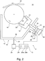
- the embodiment according to FIG. 2 is particularly suitable when a plurality, here for example two glue pots 12 are provided for the machine 10. For example, if one of the glue pots 12 is removed for cleaning, the other glue pot 12 can be used, whereby the downtime of the machine can be reduced.
- the identification means 30 may be for example a transponder or a simple mechanical coding, for example by means of a different arrangement of a pin or the like.
- the glue application device 11 further comprises a sensor 31, which is set up to determine the identification stored in the identification means 30.
- the control device can determine, by means of the signal output by the sensor 31, whether one or the other of the two glue pots 12 is inserted into the machine.
- the control device 13 contains its own memory area 25a, 25b for the corresponding current (total) path value Wa, Wb of the stripping device assigned to this glue pot 12. In this way, the individual wear of each of a particular glue pot 12 associated stripping device 21, 22 are detected, stored and evaluated individually.
- the identification means 30 may alternatively be arranged on the glue chamber 16 or the stripping device 21, 22.
Landscapes
- Manufacturing Of Cigar And Cigarette Tobacco (AREA)
- Coating Apparatus (AREA)
Description
- Die Erfindung betrifft eine Leimauftrageinrichtung für eine Maschine der Tabak verarbeitenden Industrie, umfassend eine an einer Leimwalze angeordnete Leimkammer, die relativ zu der Leimwalze nachstellbar ist, um Verschleiß einer an der Leimkammer angebrachten Abstreifeinrichtung auszugleichen. Die Erfindung betrifft weiterhin ein entsprechendes Leimauftragverfahren.
- Eine Leimauftrageinrichtung für eine Maschine der Tabak verarbeitenden Industrie, insbesondere eine Filteransetzmaschine, ist beispielsweise aus
DE 10 2008 019 434 A1 undEP 2 110 181 A2 bekannt. -
US 4 485 132 betrifft eine Maschine zum Beschichten von Metallstreifen. Die Verstellung einer Abstreifeinrichtung (doctor blade) wird gemessen und anhand dieses Messsignals die Nachstellung der Farbkammer geregelt. - Wenn die Abstreifeinrichtung verschlissen ist, kommt es zu einer Beeinträchtigung der Funktion und gegebenenfalls zu unkontrolliertem Leimauftrag. Unter Umständen kann es zu einem Anschlagen der Leimkammer an der Leimwalze und im schlimmsten Fall zu einer Beschädigung der Leimwalze kommen. Um dies zu verhindern, können kurze Wechselintervalle für die Abstreifeinrichtung vorgesehen werden, was jedoch einen häufigen Stillstand der Maschine mit sich bringt.
- Die Aufgabe der Erfindung besteht darin, eine effiziente und funktionssichere Leimauftrageinrichtung bereitzustellen, bei der eine Beschädigung der Leimwalze verhindert werden kann. Die Erfindung löst diese Aufgabe mit den Mitteln der unabhängigen Ansprüche. Mittels der erfindungsgemäßen Erfassung des Verstellwegs der Leimkammer kann der Verschleiß der Abstreifeinrichtung quantitativ in Form eines entsprechenden Wegwerts erfasst werden. Wenn der erfasste Wegwert eine vorgegebene Bedingung erfüllt, die anzeigt, dass der Verschleiß der Abstreifeinrichtung einen bestimmten maximal zulässigen Wert erreicht hat, wird ein Signal ausgegeben, um eine Auswechslung der Abstreifeinrichtung zu veranlassen. Auf diese Weise kann zuverlässig verhindert werden, dass es zu einer Überschreitung des maximal tolerierbaren Verschleißes der Abstreifeinrichtung und infolgedessen zu einem Anschlagen der Leimkammer an der Leimwalze kommt.
- Erfindungsgemäß wird bei Entnahme einer bestimmten Abstreifeinrichtung, bzw. einer entsprechenden Baueinheit, insbesondere der Leimkammer, der Wegwert zu dieser Abstreifeinrichtung gespeichert. Insbesondere bei der Verwendung einer Mehrzahl von Abstreifeinrichtungen kann vorzugsweise eine entsprechende Mehrzahl von Wegwerten gespeichert werden. Auf diese Weise ist der individuelle Wegwert jeder Abstreifeinrichtung zu einem späteren Zeitpunkt verfügbar; eine aufwändige Bestimmung und Eingabe des aktuellen Verschleißzustandes einer Abstreifeinrichtung kann dadurch vermieden werden. Insbesondere kann beim Einsetzen einer bestimmten Abstreifeinrichtung vorzugsweise ein zu dieser Abstreifeinrichtung gespeicherter Wegwert abgerufen und in der Maschinensteuerung gesetzt werden. Beim Einsetzen einer neuen, unverschlissenen Abstreifeinrichtung wird der Wegwert zweckmäßigerweise auf einen vorbestimmten Wert gesetzt, der einem Nullwert des Verschleißes entspricht. Insbesondere bei der Verwendung einer Mehrzahl von Abstreifeinrichtungen ist es vorteilhaft, ein Kennzeichnungsmittel zur individuellen Kennzeichnung jeder einzelnen Abstreifeinrichtung, bzw. einer entsprechenden Baueinheit, insbesondere der Leimkammer, vorzusehen. Mittels eines vorteilhaften Sensors kann dieses Kennzeichnungsmittel automatisch detektiert und die individuelle Kennzeichnung bestimmt werden, so dass die Maschinensteuerung insbesondere den der Abstreifeinrichtung zugeordneten Wegwert setzen kann, wodurch unbeabsichtigte Fehleinstellungen durch den Bediener vermieden werden können.
- Die erfindungsgemäße Leimauftrageinrichtung findet vorzugsweise Anwendung in einer Maschine der Tabak verarbeitenden Industrie, in der Beleimung eines Materialstreifens, insbesondere eines Papierstreifens, beispielsweise dem Belagpapier von Filterzigaretten. Die Erfindung kann daher insbesondere in Filteransetzmaschinen zur Herstellung von Filterzigaretten angewendet werden.
- Die Erfindung wird im Folgenden anhand vorteilhafter Ausführungsformen unter Bezugnahme auf die beigefügten Figuren erläutert. Dabei zeigt:
- Fig. 1:
- eine schematische Darstellung einer Leimauftrageinrichtung; und
- Fig. 2:
- eine schematische Darstellung einer Leimauftrageinrichtung in einer weiteren Ausführungsform.
- Der in
Fig. 1 gezeigte Ausschnitt einer Filteransetzmaschine 10 zeigt eine Leimauftrageinrichtung 11, die einen Leimtopf 12 und eine Steuereinrichtung 13 umfasst. Der Leimtopf 12, der insbesondere eine auswechselbare Einheit sein kann, umfasst einen Leimbehälter 14, eine in dem Leimbehälter 14 rotierbar gelagerte Leimwalze 15 und eine Leimkammer 16 zum Auftragen von Leim aus einem in der Leimkammer 16 gebildeten Hohlraum 17 auf die Leimwalze 15. Die Leimkammer 16 ist zu diesem Zweck am Umfang der Leimwalze 15 an diese anliegend angeordnet und wird mittels einer Andrückeinrichtung 18, die einen Stößel 19 und eine an einem maschinenfesten Gegenlager 32 abgestützte Krafterzeugungseinrichtung 20 zur Erzeugung einer Andrückkraft umfasst, an die Außenfläche der Leimwalze 15 angedrückt. Die Krafterzeugungseinrichtung 20 ist vorzugsweise ein insbesondere pneumatischer Zylinder, kann jedoch beispielsweise auch eine Feder oder eine elektrisch oder elektromagnetisch betriebene Einrichtung sein. Die Leimkammer 16 wird mittels nicht gezeigter Einrichtungen mit Leim versorgt. - Die rotierende Leimwalze 15 nimmt mittels an ihrer Außenfläche vorgesehenen Näpfchen Leim aus der Leimkammer 16 auf. Überschüssiger Leim wird mittels einer Abstreifeinrichtung, die im vorliegenden Beispiel von zwei Abstreifern 21, 22 bzw. Schabern gebildet ist, abgestreift. Abstreifeinrichtung bezeichnet den gesamten an einer Leimkammer 16 vorgesehenen Satz von Abstreifern 21, 22. In anderen Ausführungsformen kann die Abstreifeinrichtung von nur einem Abstreifer, oder mehr als zwei Abstreifern, gebildet sein. Der von der Leimwalze 15 aufgenommene und aus der Leimkammer 16 heraustransportierte Leim wird an einen am Außenumfang der Leimwalze 15 anliegenden, kontinuierlich geförderten Belagpapierstreifen 23 abgegeben.
- Aufgrund des kontinuierlichen Andrückens der Abstreifer 21, 22 an die Leimwalze 15 durch die Andrückvorrichtung 18 unterliegen die Abstreifer 21, 22 einem Reibungsverschleiß. Um den Anpressdruck kontinuierlich aufrechtzuerhalten, ist die Leimkammer 16, beispielsweise über den in dem Leimbehälter verschiebbar gelagerten Stößel 19, insbesondere in Pfeilrichtung, d.h. relativ zur Leimwalze 15 radial, verschiebbar gelagert und wird durch die Andrückvorrichtung 18 mit einer Vorspannung beaufschlagt. Auch eine schwenkbar gelagerte Leimkammer 16 ist denkbar.
- Die Leimauftrageinrichtung 11 umfasst vorzugsweise eine Messeinrichtung 28 zur Messung des Verschiebungsweges der Leimkammer 16. Die Messeinrichtung 28 umfasst in der in den Figuren gezeigten Ausführungsform eine in fester Verbindung zu der Leimkammer 16 stehende Messfläche 25, die im vorliegenden Beispiel von einer an dem Stößel 19 befestigten Platte 26 gebildet wird. Die Messfläche 25 kann alternativ auch von der Rückseite der Leimkammer 16 oder einer anderen geeigneten Oberfläche gebildet werden. In dem Leimtopf 12 ist weiterhin ein Abstandssensor 27 vorgesehen, der relativ zu dem Leimbehälter 14 feststeht und zur Messung des Abstands zu der Messfläche 25 geeignet ist. Der Abstandssensor 27 kann vorzugsweise ein Wirbelstromsensor oder ein anderer geeigneter Abstandssensor sein. Selbstverständlich kann alternativ der Abstandssensor 27 in fester Verbindung zu der Leimkammer 16 stehen und die Messfläche 25 relativ zu dem Leimbehälter 14 feststehen. Die Messeinrichtung 28 kann allgemein auch in Form eines Messgebers und eines mit dem Messgeber zusammenwirkenden Messnehmers realisiert sein.
- Zur Bestimmung des Verschiebungswegs der Leimkammer 16 ist nicht zwingend eine Messeinrichtung 28 erforderlich. Der Verschiebungsweg kann gegebenenfalls auch aus anderweitig verfügbarer Information ermittelt werden. Wenn beispielsweise die Krafterzeugungseinrichtung 20 einen elektrischen Schrittmotor umfasst, kann entsprechende Weginformation direkt von dem Schrittmotor bzw. der Schrittmotorsteuerung an die Steuereinrichtung 13 übermittelt werden.
- Das gemessene bzw. ermittelte Abstandssignal wird von dem Abstandssensor 27 an die Steuereinrichtung 13 übermittelt. Die Steuereinrichtung 13 ist insbesondere eine elektronische programmierte Steuerung auf der Grundlage eines Mikroprozessors bzw. Microcontrollers, insbesondere eine SPS-Steuerung. Vorzugsweise ist die Steuereinrichtung 13 in der zentralen Maschinensteuerung realisiert. Es kann sich jedoch beispielsweise auch um eine separate Steuereinheit in dem Leimtopf 12 handeln.
- In der Steuereinrichtung 13 wird beim Einsetzen eines Leimtopfes 12 mit neuen, unverschlissenen Abstreifern 21, 22 der dann ermittelte Abstandswert d0 als Anfangsabstand in einem Speicherbereich 24 gespeichert. Die im Betrieb ermittelten Abstandswerte d werden laufend oder in definierten Zeitabständen mit dem ermittelten Anfangsabstand d0 verglichen. Als Wegwert W, der den aktuellen Verschleißzustand der Abstreifeinrichtung 21, 22 beschreibt, wird der Betrag der Differenz zwischen dem Anfangsabstand d0 und dem gemessenen Abstand d ermittelt: W=|d0-d|. Der aktuelle Wegwert W wird zweckmäßigerweise in einem Speicherbereich 25 gespeichert. Wenn der Wegwert W einen vorbestimmten Wert Wmax überschreitet, stellt die Steuereinrichtung 13 fest, dass der maximal tolerierbare Verschleiß der Abstreifer 21, 22 erreicht ist, und führt durch Ausgabe eines entsprechenden Signals geeignete Maßnahmen aus. Beispielsweise kann auf einem Bedienterminal 29 ein Hinweis angezeigt werden, dass die Abstreifer 21, 22 erneuert werden müssen. Die Steuereinrichtung 13 kann auch einen Maschinenstopp veranlassen oder eine andere geeignete Maßnahme ausführen.
- Wenn der Leimtopf 12 aus der Maschine 10 entnommen werden muss, beispielsweise zur Reinigung oder infolge eines Papierrisses, wird der aktuelle Wegwert W der Abstreifeinrichtung 21, 22 in der der Steuereinrichtung 13 in einem entsprechenden Speicherbereich 25 gespeichert. Wenn der Leimtopf 12 mit denselben Abstreifern 21, 22 wieder eingesetzt wird, wird zunächst der Anfangsabstand d0 neu ermittelt. Der dann im Betrieb ermittelte aktuelle Wegwert wird dann zu dem in dem Speicherbereich 25 gespeicherten Wegwert addiert, um den aktuellen Gesamtwegwert der Abstreifeinrichtung 21, 22 zu erhalten und mit dem maximal zulässigen Wegwert Wmax zu vergleichen. Der aktuelle Gesamtwegwert W der Abstreifeinrichtung 21, 22 wird zweckmäßigerweise in dem Speicherbereich 25 gespeichert.
- Wenn ein Leimtopf 12 mit einer neuen, unverschlissenen Abstreifeinrichtung 21, 22 in die Maschine 10 eingesetzt wird, setzt die Steuereinrichtung 13 den zugehörigen aktuellen (Gesamt-)Wegwert in dem Speicherbereich 25 auf Null und ermittelt den Anfangsabstand d0 neu, der dann in dem Speicherbereich 24 gespeichert wird. Beim Einsetzen eines Leimtopfes 12 in die Maschine 10 kann beispielsweise eine Abfrage an den Bediener erfolgen, ob die Abstreifer 21, 22 erneuert wurden. Es ist auch denkbar, dies auf geeignete Weise zu detektieren, um nicht auf die Eingabe eines Bedieners angewiesen zu sein.
- Die Ausführungsform gemäß
Figur 2 ist insbesondere geeignet, wenn für die Maschine 10 eine Mehrzahl, hier beispielsweise zwei Leimtöpfe 12 vorgesehen sind. Wenn eine der Leimtöpfe 12 beispielsweise zur Reinigung entnommen wird, kann der andere Leimtopf 12 eingesetzt werden, wodurch die Stillstandzeit der Maschine reduziert werden kann. - In dieser Ausführungsform weist der bzw. jeder Leimtopf 12, hier am Leimbehälter 14, ein Kennzeichnungsmittel 30 auf, das eine eindeutige Kennzeichnung des Leimtopfes 12 und damit der dem Leimtopf zugeordneten Abstreifeinrichtung 21, 22 enthält. Das Kennzeichnungsmittel 30 kann beispielsweise ein Transponder oder eine einfache mechanische Kodierung, beispielsweise mittels unterschiedlicher Anordnung eines Stiftes oder dergleichen, sein.
- Die Leimauftrageinrichtung 11 umfasst des Weiteren einen Sensor 31, der zur Ermittlung der in dem Kennzeichnungsmittel 30 gespeicherten Kennzeichnung eingerichtet ist. Im vorliegenden Beispiel kann die Steuereinrichtung mittels des von dem Sensor 31 ausgegebenen Signals feststellen, ob der eine oder der andere der beiden Leimtöpfe 12 in die Maschine eingesetzt ist. Die Steuereinrichtung 13 enthält für jeden der verwendeten Leimtöpfe 12 einen eigenen Speicherbereich 25a, 25b für den entsprechenden aktuellen (Gesamt-)Wegwert Wa, Wb der diesem Leimtopf 12 zugeordneten Abstreifvorrichtung. Auf diese Weise kann der individuelle Verschleiß jeder einem bestimmten Leimtopf 12 zugeordneten Abstreifeinrichtung 21, 22 individuell erfasst, gespeichert und ausgewertet werden.
- In einer nicht gezeigten Ausführungsform kann das Kennzeichnungsmittel 30 alternativ an der Leimkammer 16 oder der Abstreifeinrichtung 21, 22 angeordnet sein.
Claims (10)
- Leimauftrageinrichtung (11) für eine Maschine der Tabak verarbeitenden Industrie, umfassend eine an einer Leimwalze (15) angeordnete Leimkammer (16), die relativ zu der Leimwalze (15) nachstellbar ist, um Verschleiß einer an der Leimkammer (16) angebrachten Abstreifeinrichtung (21, 22) auszugleichen, dadurch gekennzeichnet, dass die Leimauftrageinrichtung Mittel (28) zum Erfassen eines mit dem Verstellweg der Leimkammer (16) zusammenhängenden Wegwerts und zum Ausgeben eines Signals, wenn der Wegwert eine vorgegebene Bedingung erfüllt, umfasst, wobei die Leimauftrageinrichtung bei Entnahme einer Abstreifeinrichtung (21, 22) zum Speichern des Wegwerts zu dieser Abstreifeinrichtung (21, 22) eingerichtet ist.
- Leimauftrageinrichtung nach Anspruch 1, dadurch gekennzeichnet, dass die Leimauftrageinrichtung beim Einsetzen einer Abstreifeinrichtung (21, 22) zum Abrufen und Setzen eines zu dieser Abstreifeinrichtung gespeicherten Wegwerts eingerichtet ist.
- Leimauftrageinrichtung nach einem der vorangehenden Ansprüche, dadurch gekennzeichnet, dass die Leimauftrageinrichtung beim Einsetzen einer neuen Abstreifeinrichtung (21, 22) zum Setzen des Wegwerts auf einen vorbestimmten Wert eingerichtet ist.
- Leimauftrageinrichtung nach einem der vorangehenden Ansprüche, dadurch gekennzeichnet, dass die Leimauftrageinrichtung zum Speichern einer Mehrzahl von Wegwerten entsprechend einer Mehrzahl von Abstreifeinrichtungen (21, 22) eingerichtet ist.
- Leimauftrageinrichtung nach einem der vorangehenden Ansprüche, dadurch gekennzeichnet, dass das Erfassungsmittel (28) einen Sensor (27) zum Messen eines Abstands der Leimkammer (16) relativ zu einem Leimtopf (12) umfasst.
- Leimauftrageinrichtung nach Anspruch 5, dadurch gekennzeichnet, dass der Sensor (27) ein Wirbelstromsensor ist.
- Leimauftrageinrichtung nach einem der vorangehenden Ansprüche, umfassend ein Kennzeichnungsmittel (30) für die Abstreifeinrichtung (21, 22).
- Leimauftrageinrichtung nach Anspruch 7, umfassend einen Sensor (31) zum Detektieren des Kennzeichnungsmittels (30).
- Maschine der Tabak verarbeitenden Industrie, insbesondere Filteransetzmaschine (10), umfassend eine Leimauftrageinrichtung (11) nach einem der vorangehenden Ansprüche.
- Leimauftragverfahren für eine Maschine der Tabak verarbeitenden Industrie, umfassend das Nachstellen einer an einer Leimwalze (15) angeordneten Leimkammer (16) relativ zu der Leimwalze (15), um Verschleiß einer an der Leimkammer (16) angebrachten Abstreifeinrichtung (21, 22) auszugleichen, gekennzeichnet durch das Erfassen eines mit dem Verstellweg der Leimkammer (16) zusammenhängenden Wegwerts und Ausgeben eines Signals, wenn der Wegwert eine vorgegebene Bedingung erfüllt, und bei Entnahme einer Abstreifeinrichtung (21, 22) Speichern des Wegwerts zu dieser Abstreifeinrichtung (21, 22).
Priority Applications (1)
| Application Number | Priority Date | Filing Date | Title |
|---|---|---|---|
| PL10781431T PL2506728T3 (pl) | 2009-11-30 | 2010-11-10 | Urządzenie i sposób do nanoszenia kleju dla maszyny przemysłu tytoniowego |
Applications Claiming Priority (2)
| Application Number | Priority Date | Filing Date | Title |
|---|---|---|---|
| DE102009056065.3A DE102009056065B4 (de) | 2009-11-30 | 2009-11-30 | Leimauftrageinrichtung und -verfahren für eine Maschine der Tabak verarbeitenden Industrie |
| PCT/EP2010/006845 WO2011063895A1 (de) | 2009-11-30 | 2010-11-10 | Leimauftrageinrichtung und -verfahren für eine maschine der tabak verarbeitenden industrie |
Publications (2)
| Publication Number | Publication Date |
|---|---|
| EP2506728A1 EP2506728A1 (de) | 2012-10-10 |
| EP2506728B1 true EP2506728B1 (de) | 2017-01-04 |
Family
ID=43533263
Family Applications (1)
| Application Number | Title | Priority Date | Filing Date |
|---|---|---|---|
| EP10781431.1A Not-in-force EP2506728B1 (de) | 2009-11-30 | 2010-11-10 | Leimauftrageinrichtung und -verfahren für eine maschine der tabak verarbeitenden industrie |
Country Status (5)
| Country | Link |
|---|---|
| EP (1) | EP2506728B1 (de) |
| CN (1) | CN102665455B (de) |
| DE (1) | DE102009056065B4 (de) |
| PL (1) | PL2506728T3 (de) |
| WO (1) | WO2011063895A1 (de) |
Families Citing this family (7)
| Publication number | Priority date | Publication date | Assignee | Title |
|---|---|---|---|---|
| DE102013209963A1 (de) | 2013-05-28 | 2014-12-18 | Siemens Aktiengesellschaft | Anordnung zum Aufrakeln eines Pulvers |
| CN103418524B (zh) * | 2013-06-19 | 2015-09-16 | 宁波职业技术学院 | 一种供胶均匀的涂胶装置 |
| CN103962923B (zh) * | 2014-05-22 | 2017-01-25 | 浙江梦天木业有限公司 | 木线打磨滚涂一体机 |
| CN117019515B (zh) * | 2023-10-09 | 2023-12-15 | 常州润来科技有限公司 | 一种凹版涂胶装置及方法 |
| DE102024209489A1 (de) * | 2024-09-30 | 2026-04-02 | Schaeffler Technologies AG & Co. KG | Verfahren zum Ermitteln eines Bürstenverschleißes eines - einen sensorlosen Schrittmotor aufweisenden - nasslaufenden Bürstenstellers, Computerprogramm, Computerprogrammprodukt, System und Elektrofahrzeug |
| DE102024209485A1 (de) * | 2024-09-30 | 2026-04-02 | Schaeffler Technologies AG & Co. KG | Verfahren zum Einstellen eines sensorlosen Schrittmotors eines nasslaufenden Bürstenstellers, Computerprogramm, Computerprogrammprodukt, System und Elektrofahrzeug |
| CN119838809B (zh) * | 2024-12-27 | 2025-10-31 | 楚天科技股份有限公司 | 一种涂布装置的涂布刮刀高度调节方法、系统和介质 |
Family Cites Families (7)
| Publication number | Priority date | Publication date | Assignee | Title |
|---|---|---|---|---|
| JPS5814970A (ja) * | 1981-07-17 | 1983-01-28 | Nisshin Steel Co Ltd | 金属帯状材料の連続塗装方法 |
| IT1295221B1 (it) * | 1997-10-14 | 1999-05-04 | Gd Spa | Dispositivo gommatore. |
| ITMO20020271A1 (it) * | 2002-09-27 | 2004-03-28 | Syfal Spa | Apparecchiatura per la regolazione del posizionamento |
| DE50207576D1 (de) * | 2002-11-29 | 2006-08-31 | Hauni Maschinenbau Ag | Umlaufendes Förderband zum Fördern eines Strangs der tabakverarbeitenden Industrie |
| CN201174969Y (zh) * | 2008-03-26 | 2009-01-07 | 新乡东方工业科技有限公司 | 一种卷烟机上的供胶机构 |
| DE102008019433A1 (de) * | 2008-04-17 | 2009-12-03 | Hauni Maschinenbau Ag | Beleimung von Materialstreifen der Tabak verarbeitenden Industrie |
| DE102008019434B4 (de) * | 2008-04-17 | 2013-08-22 | Hauni Maschinenbau Ag | Beleimung von Materialstreifen der Tabak verarbeitenden Industrie |
-
2009
- 2009-11-30 DE DE102009056065.3A patent/DE102009056065B4/de not_active Expired - Fee Related
-
2010
- 2010-11-10 WO PCT/EP2010/006845 patent/WO2011063895A1/de not_active Ceased
- 2010-11-10 EP EP10781431.1A patent/EP2506728B1/de not_active Not-in-force
- 2010-11-10 PL PL10781431T patent/PL2506728T3/pl unknown
- 2010-11-10 CN CN201080054222.1A patent/CN102665455B/zh not_active Expired - Fee Related
Non-Patent Citations (1)
| Title |
|---|
| None * |
Also Published As
| Publication number | Publication date |
|---|---|
| PL2506728T3 (pl) | 2017-06-30 |
| DE102009056065B4 (de) | 2021-03-18 |
| CN102665455A (zh) | 2012-09-12 |
| EP2506728A1 (de) | 2012-10-10 |
| CN102665455B (zh) | 2016-03-09 |
| DE102009056065A1 (de) | 2011-06-01 |
| WO2011063895A1 (de) | 2011-06-03 |
Similar Documents
| Publication | Publication Date | Title |
|---|---|---|
| EP2506728A1 (de) | Leimauftrageinrichtung und -verfahren für eine maschine der tabak verarbeitenden industrie | |
| AT510024B1 (de) | Plastifiziereinheit mit verschleissmesssensor | |
| EP3269265B1 (de) | Schneiden eines belagpapierstreifens der tabak verarbeitenden industrie | |
| EP2062485B9 (de) | Druckwerk mit Steuerung der Drehgeschwindigkeit einer Druckwalze | |
| EP2389279A1 (de) | Vorrichtung und verfahren zur einstellung eines schneidspalts an einer schneidvorrichtung | |
| EP2707207B1 (de) | Abstreifeinrichtung für eine rundläuferpresse, rundläuferpresse und verfahren zum betreiben einer rundläuferpresse | |
| EP3727830B1 (de) | Vorrichtung und verfahren zur überwachung eines keiltriebwerkzeuges | |
| EP2001661A1 (de) | Vorrichtung und verfahren zum aufbau eines reifens | |
| EP2030515B1 (de) | Vorrichtung und Verfahren zum Schleifen von Schneidmessern | |
| DE3039130A1 (de) | Steuerschaltung fuer eine vorrichtung zum nachstellen und abrichten einer schleifscheibe | |
| WO2011063896A1 (de) | Leimauftrageinrichtung und -verfahren für eine maschine der tabak verarbeitenden industrie | |
| EP1537772B1 (de) | Häckselvorrichtung mit Schleifvorrichtung | |
| EP0627309B1 (de) | Verfahren zum Einstellen der Berührung zweier im Abstand zueinander verstellbarer Walzen | |
| DE102014215232B3 (de) | Schneideinrichtung zum Schneiden von stabförmigen oder strangförmigen Produkten der Tabak verarbeitenden Industrie | |
| DE4436582C2 (de) | Verfahren zur Regelung einer Feuchtmittelmenge für eine Druckform einer laufenden Offsetrotationsdruckmaschine | |
| DE102018002036B3 (de) | Verfahren zum Betrieb einer Schneidvorrichtung, insbesondere zur Borstenbearbeitung einer Bürste, und Schneidvorrichtung | |
| EP0946368A2 (de) | Farbkasten | |
| EP0526500B1 (de) | Verfahren zur schnittqualitätserfassung einer schneidmaschine für papier, pappe oder dergleichen sowie schneidmaschine | |
| DE102005018800A1 (de) | Verfahren zum Längsschneiden einer laufenden Materialbahn | |
| EP2168768B1 (de) | Offsetdruckmaschine | |
| DE102021105515A1 (de) | Verfahren zum Schleifen eines Stanzbelages sowie Bogenbearbeitungsmaschine mit einem Stanzaggregat | |
| EP1757522A1 (de) | Verfahren und Clipvorrichtung zum Verschliessen wurstförmiger Verpackungen | |
| DE19640416B4 (de) | Schleifvorrichtung für das Messer von Entschleif- oder Spaltmaschinen | |
| EP2060520A2 (de) | Verfahren zur Einstellung des Bremsspalts einer Verlangsamungsvorrichtung für Flachprodukte sowie hierfür eingerichtete Verlangsamungsvorrichtung | |
| WO2004017771A1 (de) | Verfahren zum betrieb einer herstellungs- oder verpackungsmaschine der tabakverarbeitenden industrie |
Legal Events
| Date | Code | Title | Description |
|---|---|---|---|
| PUAI | Public reference made under article 153(3) epc to a published international application that has entered the european phase |
Free format text: ORIGINAL CODE: 0009012 |
|
| 17P | Request for examination filed |
Effective date: 20120326 |
|
| AK | Designated contracting states |
Kind code of ref document: A1 Designated state(s): AL AT BE BG CH CY CZ DE DK EE ES FI FR GB GR HR HU IE IS IT LI LT LU LV MC MK MT NL NO PL PT RO RS SE SI SK SM TR |
|
| DAX | Request for extension of the european patent (deleted) | ||
| GRAP | Despatch of communication of intention to grant a patent |
Free format text: ORIGINAL CODE: EPIDOSNIGR1 |
|
| RAP1 | Party data changed (applicant data changed or rights of an application transferred) |
Owner name: HAUNI MASCHINENBAU GMBH |
|
| RIC1 | Information provided on ipc code assigned before grant |
Ipc: B05C 11/10 20060101ALI20160627BHEP Ipc: B05C 1/08 20060101ALI20160627BHEP Ipc: A24C 5/47 20060101AFI20160627BHEP |
|
| INTG | Intention to grant announced |
Effective date: 20160712 |
|
| GRAS | Grant fee paid |
Free format text: ORIGINAL CODE: EPIDOSNIGR3 |
|
| GRAA | (expected) grant |
Free format text: ORIGINAL CODE: 0009210 |
|
| AK | Designated contracting states |
Kind code of ref document: B1 Designated state(s): AL AT BE BG CH CY CZ DE DK EE ES FI FR GB GR HR HU IE IS IT LI LT LU LV MC MK MT NL NO PL PT RO RS SE SI SK SM TR |
|
| REG | Reference to a national code |
Ref country code: GB Ref legal event code: FG4D Free format text: NOT ENGLISH |
|
| REG | Reference to a national code |
Ref country code: CH Ref legal event code: EP |
|
| REG | Reference to a national code |
Ref country code: AT Ref legal event code: REF Ref document number: 858342 Country of ref document: AT Kind code of ref document: T Effective date: 20170115 |
|
| REG | Reference to a national code |
Ref country code: IE Ref legal event code: FG4D Free format text: LANGUAGE OF EP DOCUMENT: GERMAN |
|
| REG | Reference to a national code |
Ref country code: DE Ref legal event code: R096 Ref document number: 502010013005 Country of ref document: DE |
|
| REG | Reference to a national code |
Ref country code: NL Ref legal event code: FP |
|
| REG | Reference to a national code |
Ref country code: LT Ref legal event code: MG4D |
|
| PG25 | Lapsed in a contracting state [announced via postgrant information from national office to epo] |
Ref country code: NO Free format text: LAPSE BECAUSE OF FAILURE TO SUBMIT A TRANSLATION OF THE DESCRIPTION OR TO PAY THE FEE WITHIN THE PRESCRIBED TIME-LIMIT Effective date: 20170404 Ref country code: HR Free format text: LAPSE BECAUSE OF FAILURE TO SUBMIT A TRANSLATION OF THE DESCRIPTION OR TO PAY THE FEE WITHIN THE PRESCRIBED TIME-LIMIT Effective date: 20170104 Ref country code: FI Free format text: LAPSE BECAUSE OF FAILURE TO SUBMIT A TRANSLATION OF THE DESCRIPTION OR TO PAY THE FEE WITHIN THE PRESCRIBED TIME-LIMIT Effective date: 20170104 Ref country code: GR Free format text: LAPSE BECAUSE OF FAILURE TO SUBMIT A TRANSLATION OF THE DESCRIPTION OR TO PAY THE FEE WITHIN THE PRESCRIBED TIME-LIMIT Effective date: 20170405 Ref country code: LT Free format text: LAPSE BECAUSE OF FAILURE TO SUBMIT A TRANSLATION OF THE DESCRIPTION OR TO PAY THE FEE WITHIN THE PRESCRIBED TIME-LIMIT Effective date: 20170104 Ref country code: IS Free format text: LAPSE BECAUSE OF FAILURE TO SUBMIT A TRANSLATION OF THE DESCRIPTION OR TO PAY THE FEE WITHIN THE PRESCRIBED TIME-LIMIT Effective date: 20170504 |
|
| PG25 | Lapsed in a contracting state [announced via postgrant information from national office to epo] |
Ref country code: ES Free format text: LAPSE BECAUSE OF FAILURE TO SUBMIT A TRANSLATION OF THE DESCRIPTION OR TO PAY THE FEE WITHIN THE PRESCRIBED TIME-LIMIT Effective date: 20170104 Ref country code: LV Free format text: LAPSE BECAUSE OF FAILURE TO SUBMIT A TRANSLATION OF THE DESCRIPTION OR TO PAY THE FEE WITHIN THE PRESCRIBED TIME-LIMIT Effective date: 20170104 Ref country code: RS Free format text: LAPSE BECAUSE OF FAILURE TO SUBMIT A TRANSLATION OF THE DESCRIPTION OR TO PAY THE FEE WITHIN THE PRESCRIBED TIME-LIMIT Effective date: 20170104 Ref country code: BG Free format text: LAPSE BECAUSE OF FAILURE TO SUBMIT A TRANSLATION OF THE DESCRIPTION OR TO PAY THE FEE WITHIN THE PRESCRIBED TIME-LIMIT Effective date: 20170404 Ref country code: SE Free format text: LAPSE BECAUSE OF FAILURE TO SUBMIT A TRANSLATION OF THE DESCRIPTION OR TO PAY THE FEE WITHIN THE PRESCRIBED TIME-LIMIT Effective date: 20170104 Ref country code: PT Free format text: LAPSE BECAUSE OF FAILURE TO SUBMIT A TRANSLATION OF THE DESCRIPTION OR TO PAY THE FEE WITHIN THE PRESCRIBED TIME-LIMIT Effective date: 20170504 |
|
| REG | Reference to a national code |
Ref country code: DE Ref legal event code: R097 Ref document number: 502010013005 Country of ref document: DE |
|
| PG25 | Lapsed in a contracting state [announced via postgrant information from national office to epo] |
Ref country code: CZ Free format text: LAPSE BECAUSE OF FAILURE TO SUBMIT A TRANSLATION OF THE DESCRIPTION OR TO PAY THE FEE WITHIN THE PRESCRIBED TIME-LIMIT Effective date: 20170104 Ref country code: SK Free format text: LAPSE BECAUSE OF FAILURE TO SUBMIT A TRANSLATION OF THE DESCRIPTION OR TO PAY THE FEE WITHIN THE PRESCRIBED TIME-LIMIT Effective date: 20170104 Ref country code: EE Free format text: LAPSE BECAUSE OF FAILURE TO SUBMIT A TRANSLATION OF THE DESCRIPTION OR TO PAY THE FEE WITHIN THE PRESCRIBED TIME-LIMIT Effective date: 20170104 Ref country code: RO Free format text: LAPSE BECAUSE OF FAILURE TO SUBMIT A TRANSLATION OF THE DESCRIPTION OR TO PAY THE FEE WITHIN THE PRESCRIBED TIME-LIMIT Effective date: 20170104 |
|
| PLBE | No opposition filed within time limit |
Free format text: ORIGINAL CODE: 0009261 |
|
| STAA | Information on the status of an ep patent application or granted ep patent |
Free format text: STATUS: NO OPPOSITION FILED WITHIN TIME LIMIT |
|
| PG25 | Lapsed in a contracting state [announced via postgrant information from national office to epo] |
Ref country code: SM Free format text: LAPSE BECAUSE OF FAILURE TO SUBMIT A TRANSLATION OF THE DESCRIPTION OR TO PAY THE FEE WITHIN THE PRESCRIBED TIME-LIMIT Effective date: 20170104 Ref country code: DK Free format text: LAPSE BECAUSE OF FAILURE TO SUBMIT A TRANSLATION OF THE DESCRIPTION OR TO PAY THE FEE WITHIN THE PRESCRIBED TIME-LIMIT Effective date: 20170104 |
|
| 26N | No opposition filed |
Effective date: 20171005 |
|
| PG25 | Lapsed in a contracting state [announced via postgrant information from national office to epo] |
Ref country code: SI Free format text: LAPSE BECAUSE OF FAILURE TO SUBMIT A TRANSLATION OF THE DESCRIPTION OR TO PAY THE FEE WITHIN THE PRESCRIBED TIME-LIMIT Effective date: 20170104 |
|
| PG25 | Lapsed in a contracting state [announced via postgrant information from national office to epo] |
Ref country code: MC Free format text: LAPSE BECAUSE OF FAILURE TO SUBMIT A TRANSLATION OF THE DESCRIPTION OR TO PAY THE FEE WITHIN THE PRESCRIBED TIME-LIMIT Effective date: 20170104 |
|
| GBPC | Gb: european patent ceased through non-payment of renewal fee |
Effective date: 20171110 |
|
| PG25 | Lapsed in a contracting state [announced via postgrant information from national office to epo] |
Ref country code: LI Free format text: LAPSE BECAUSE OF NON-PAYMENT OF DUE FEES Effective date: 20171130 Ref country code: CH Free format text: LAPSE BECAUSE OF NON-PAYMENT OF DUE FEES Effective date: 20171130 |
|
| PG25 | Lapsed in a contracting state [announced via postgrant information from national office to epo] |
Ref country code: LU Free format text: LAPSE BECAUSE OF NON-PAYMENT OF DUE FEES Effective date: 20171110 |
|
| REG | Reference to a national code |
Ref country code: FR Ref legal event code: ST Effective date: 20180731 Ref country code: BE Ref legal event code: MM Effective date: 20171130 |
|
| REG | Reference to a national code |
Ref country code: IE Ref legal event code: MM4A |
|
| PG25 | Lapsed in a contracting state [announced via postgrant information from national office to epo] |
Ref country code: MT Free format text: LAPSE BECAUSE OF FAILURE TO SUBMIT A TRANSLATION OF THE DESCRIPTION OR TO PAY THE FEE WITHIN THE PRESCRIBED TIME-LIMIT Effective date: 20170104 |
|
| PG25 | Lapsed in a contracting state [announced via postgrant information from national office to epo] |
Ref country code: IE Free format text: LAPSE BECAUSE OF NON-PAYMENT OF DUE FEES Effective date: 20171110 Ref country code: FR Free format text: LAPSE BECAUSE OF NON-PAYMENT OF DUE FEES Effective date: 20171130 |
|
| PG25 | Lapsed in a contracting state [announced via postgrant information from national office to epo] |
Ref country code: GB Free format text: LAPSE BECAUSE OF NON-PAYMENT OF DUE FEES Effective date: 20171110 Ref country code: BE Free format text: LAPSE BECAUSE OF NON-PAYMENT OF DUE FEES Effective date: 20171130 |
|
| REG | Reference to a national code |
Ref country code: AT Ref legal event code: MM01 Ref document number: 858342 Country of ref document: AT Kind code of ref document: T Effective date: 20171110 |
|
| PG25 | Lapsed in a contracting state [announced via postgrant information from national office to epo] |
Ref country code: AT Free format text: LAPSE BECAUSE OF NON-PAYMENT OF DUE FEES Effective date: 20171110 |
|
| PG25 | Lapsed in a contracting state [announced via postgrant information from national office to epo] |
Ref country code: HU Free format text: LAPSE BECAUSE OF FAILURE TO SUBMIT A TRANSLATION OF THE DESCRIPTION OR TO PAY THE FEE WITHIN THE PRESCRIBED TIME-LIMIT; INVALID AB INITIO Effective date: 20101110 |
|
| PG25 | Lapsed in a contracting state [announced via postgrant information from national office to epo] |
Ref country code: CY Free format text: LAPSE BECAUSE OF NON-PAYMENT OF DUE FEES Effective date: 20170104 |
|
| PG25 | Lapsed in a contracting state [announced via postgrant information from national office to epo] |
Ref country code: MK Free format text: LAPSE BECAUSE OF FAILURE TO SUBMIT A TRANSLATION OF THE DESCRIPTION OR TO PAY THE FEE WITHIN THE PRESCRIBED TIME-LIMIT Effective date: 20170104 |
|
| PGFP | Annual fee paid to national office [announced via postgrant information from national office to epo] |
Ref country code: DE Payment date: 20191128 Year of fee payment: 10 Ref country code: NL Payment date: 20191122 Year of fee payment: 10 |
|
| PGFP | Annual fee paid to national office [announced via postgrant information from national office to epo] |
Ref country code: IT Payment date: 20191129 Year of fee payment: 10 Ref country code: PL Payment date: 20191025 Year of fee payment: 10 |
|
| PG25 | Lapsed in a contracting state [announced via postgrant information from national office to epo] |
Ref country code: TR Free format text: LAPSE BECAUSE OF FAILURE TO SUBMIT A TRANSLATION OF THE DESCRIPTION OR TO PAY THE FEE WITHIN THE PRESCRIBED TIME-LIMIT Effective date: 20170104 |
|
| PG25 | Lapsed in a contracting state [announced via postgrant information from national office to epo] |
Ref country code: AL Free format text: LAPSE BECAUSE OF FAILURE TO SUBMIT A TRANSLATION OF THE DESCRIPTION OR TO PAY THE FEE WITHIN THE PRESCRIBED TIME-LIMIT Effective date: 20170104 |
|
| REG | Reference to a national code |
Ref country code: DE Ref legal event code: R119 Ref document number: 502010013005 Country of ref document: DE |
|
| REG | Reference to a national code |
Ref country code: NL Ref legal event code: MM Effective date: 20201201 |
|
| PG25 | Lapsed in a contracting state [announced via postgrant information from national office to epo] |
Ref country code: NL Free format text: LAPSE BECAUSE OF NON-PAYMENT OF DUE FEES Effective date: 20201201 |
|
| PG25 | Lapsed in a contracting state [announced via postgrant information from national office to epo] |
Ref country code: IT Free format text: LAPSE BECAUSE OF NON-PAYMENT OF DUE FEES Effective date: 20201110 |
|
| PG25 | Lapsed in a contracting state [announced via postgrant information from national office to epo] |
Ref country code: DE Free format text: LAPSE BECAUSE OF NON-PAYMENT OF DUE FEES Effective date: 20210601 |
|
| PG25 | Lapsed in a contracting state [announced via postgrant information from national office to epo] |
Ref country code: PL Free format text: LAPSE BECAUSE OF NON-PAYMENT OF DUE FEES Effective date: 20201110 |