EP2506065B1 - Identification medium and identification method therefor - Google Patents
Identification medium and identification method therefor Download PDFInfo
- Publication number
- EP2506065B1 EP2506065B1 EP10833089.5A EP10833089A EP2506065B1 EP 2506065 B1 EP2506065 B1 EP 2506065B1 EP 10833089 A EP10833089 A EP 10833089A EP 2506065 B1 EP2506065 B1 EP 2506065B1
- Authority
- EP
- European Patent Office
- Prior art keywords
- layer
- light
- identification medium
- optical anisotropic
- polarization filter
- Prior art date
- Legal status (The legal status is an assumption and is not a legal conclusion. Google has not performed a legal analysis and makes no representation as to the accuracy of the status listed.)
- Not-in-force
Links
- 238000000034 method Methods 0.000 title claims description 23
- 230000010287 polarization Effects 0.000 claims description 164
- 230000003287 optical effect Effects 0.000 claims description 110
- 239000002184 metal Substances 0.000 claims description 28
- 239000010410 layer Substances 0.000 description 282
- 239000004986 Cholesteric liquid crystals (ChLC) Substances 0.000 description 59
- 230000000694 effects Effects 0.000 description 19
- 239000012790 adhesive layer Substances 0.000 description 16
- 239000003086 colorant Substances 0.000 description 14
- 238000012546 transfer Methods 0.000 description 12
- 239000000463 material Substances 0.000 description 11
- 230000008859 change Effects 0.000 description 8
- 230000005540 biological transmission Effects 0.000 description 7
- 239000004973 liquid crystal related substance Substances 0.000 description 7
- 238000004519 manufacturing process Methods 0.000 description 7
- 238000004049 embossing Methods 0.000 description 5
- 229920000642 polymer Polymers 0.000 description 5
- 239000002861 polymer material Substances 0.000 description 5
- 230000008569 process Effects 0.000 description 5
- 150000001875 compounds Chemical class 0.000 description 4
- 238000013461 design Methods 0.000 description 4
- 238000010438 heat treatment Methods 0.000 description 4
- 238000006116 polymerization reaction Methods 0.000 description 4
- 238000001228 spectrum Methods 0.000 description 4
- ZWEHNKRNPOVVGH-UHFFFAOYSA-N 2-Butanone Chemical compound CCC(C)=O ZWEHNKRNPOVVGH-UHFFFAOYSA-N 0.000 description 3
- 238000007796 conventional method Methods 0.000 description 3
- UWCWUCKPEYNDNV-LBPRGKRZSA-N 2,6-dimethyl-n-[[(2s)-pyrrolidin-2-yl]methyl]aniline Chemical compound CC1=CC=CC(C)=C1NC[C@H]1NCCC1 UWCWUCKPEYNDNV-LBPRGKRZSA-N 0.000 description 2
- 229920002284 Cellulose triacetate Polymers 0.000 description 2
- 229920000089 Cyclic olefin copolymer Polymers 0.000 description 2
- 206010034972 Photosensitivity reaction Diseases 0.000 description 2
- 239000004372 Polyvinyl alcohol Substances 0.000 description 2
- NNLVGZFZQQXQNW-ADJNRHBOSA-N [(2r,3r,4s,5r,6s)-4,5-diacetyloxy-3-[(2s,3r,4s,5r,6r)-3,4,5-triacetyloxy-6-(acetyloxymethyl)oxan-2-yl]oxy-6-[(2r,3r,4s,5r,6s)-4,5,6-triacetyloxy-2-(acetyloxymethyl)oxan-3-yl]oxyoxan-2-yl]methyl acetate Chemical compound O([C@@H]1O[C@@H]([C@H]([C@H](OC(C)=O)[C@H]1OC(C)=O)O[C@H]1[C@@H]([C@@H](OC(C)=O)[C@H](OC(C)=O)[C@@H](COC(C)=O)O1)OC(C)=O)COC(=O)C)[C@@H]1[C@@H](COC(C)=O)O[C@@H](OC(C)=O)[C@H](OC(C)=O)[C@H]1OC(C)=O NNLVGZFZQQXQNW-ADJNRHBOSA-N 0.000 description 2
- 238000010521 absorption reaction Methods 0.000 description 2
- 239000000853 adhesive Substances 0.000 description 2
- 230000001070 adhesive effect Effects 0.000 description 2
- 230000015572 biosynthetic process Effects 0.000 description 2
- 239000003795 chemical substances by application Substances 0.000 description 2
- 239000007822 coupling agent Substances 0.000 description 2
- 238000005286 illumination Methods 0.000 description 2
- 230000005865 ionizing radiation Effects 0.000 description 2
- 230000031700 light absorption Effects 0.000 description 2
- 239000002932 luster Substances 0.000 description 2
- 230000036211 photosensitivity Effects 0.000 description 2
- 239000000049 pigment Substances 0.000 description 2
- 239000004417 polycarbonate Substances 0.000 description 2
- 229920002451 polyvinyl alcohol Polymers 0.000 description 2
- ZCYVEMRRCGMTRW-UHFFFAOYSA-N 7553-56-2 Chemical compound [I] ZCYVEMRRCGMTRW-UHFFFAOYSA-N 0.000 description 1
- 229920002799 BoPET Polymers 0.000 description 1
- 239000004976 Lyotropic liquid crystal Substances 0.000 description 1
- 230000009471 action Effects 0.000 description 1
- 238000013459 approach Methods 0.000 description 1
- 239000007767 bonding agent Substances 0.000 description 1
- 238000012663 cationic photopolymerization Methods 0.000 description 1
- 230000003247 decreasing effect Effects 0.000 description 1
- 230000001419 dependent effect Effects 0.000 description 1
- 230000006866 deterioration Effects 0.000 description 1
- 238000009826 distribution Methods 0.000 description 1
- 238000001704 evaporation Methods 0.000 description 1
- 238000005562 fading Methods 0.000 description 1
- 239000003999 initiator Substances 0.000 description 1
- 229910052740 iodine Inorganic materials 0.000 description 1
- 239000011630 iodine Substances 0.000 description 1
- 239000007788 liquid Substances 0.000 description 1
- 238000012986 modification Methods 0.000 description 1
- 230000004048 modification Effects 0.000 description 1
- 239000000178 monomer Substances 0.000 description 1
- 229920000515 polycarbonate Polymers 0.000 description 1
- -1 polyethylene terephthalate Polymers 0.000 description 1
- 229920000139 polyethylene terephthalate Polymers 0.000 description 1
- 239000005020 polyethylene terephthalate Substances 0.000 description 1
- 238000012545 processing Methods 0.000 description 1
- 239000011347 resin Substances 0.000 description 1
- 229920005989 resin Polymers 0.000 description 1
- 239000005268 rod-like liquid crystal Substances 0.000 description 1
- 239000012780 transparent material Substances 0.000 description 1
Images

Classifications
-
- B—PERFORMING OPERATIONS; TRANSPORTING
- B42—BOOKBINDING; ALBUMS; FILES; SPECIAL PRINTED MATTER
- B42D—BOOKS; BOOK COVERS; LOOSE LEAVES; PRINTED MATTER CHARACTERISED BY IDENTIFICATION OR SECURITY FEATURES; PRINTED MATTER OF SPECIAL FORMAT OR STYLE NOT OTHERWISE PROVIDED FOR; DEVICES FOR USE THEREWITH AND NOT OTHERWISE PROVIDED FOR; MOVABLE-STRIP WRITING OR READING APPARATUS
- B42D25/00—Information-bearing cards or sheet-like structures characterised by identification or security features; Manufacture thereof
- B42D25/30—Identification or security features, e.g. for preventing forgery
- B42D25/36—Identification or security features, e.g. for preventing forgery comprising special materials
- B42D25/364—Liquid crystals
-
- G—PHYSICS
- G02—OPTICS
- G02B—OPTICAL ELEMENTS, SYSTEMS OR APPARATUS
- G02B5/00—Optical elements other than lenses
- G02B5/30—Polarising elements
-
- B—PERFORMING OPERATIONS; TRANSPORTING
- B42—BOOKBINDING; ALBUMS; FILES; SPECIAL PRINTED MATTER
- B42D—BOOKS; BOOK COVERS; LOOSE LEAVES; PRINTED MATTER CHARACTERISED BY IDENTIFICATION OR SECURITY FEATURES; PRINTED MATTER OF SPECIAL FORMAT OR STYLE NOT OTHERWISE PROVIDED FOR; DEVICES FOR USE THEREWITH AND NOT OTHERWISE PROVIDED FOR; MOVABLE-STRIP WRITING OR READING APPARATUS
- B42D15/00—Printed matter of special format or style not otherwise provided for
-
- B—PERFORMING OPERATIONS; TRANSPORTING
- B42—BOOKBINDING; ALBUMS; FILES; SPECIAL PRINTED MATTER
- B42D—BOOKS; BOOK COVERS; LOOSE LEAVES; PRINTED MATTER CHARACTERISED BY IDENTIFICATION OR SECURITY FEATURES; PRINTED MATTER OF SPECIAL FORMAT OR STYLE NOT OTHERWISE PROVIDED FOR; DEVICES FOR USE THEREWITH AND NOT OTHERWISE PROVIDED FOR; MOVABLE-STRIP WRITING OR READING APPARATUS
- B42D25/00—Information-bearing cards or sheet-like structures characterised by identification or security features; Manufacture thereof
- B42D25/20—Information-bearing cards or sheet-like structures characterised by identification or security features; Manufacture thereof characterised by a particular use or purpose
- B42D25/29—Securities; Bank notes
-
- B—PERFORMING OPERATIONS; TRANSPORTING
- B42—BOOKBINDING; ALBUMS; FILES; SPECIAL PRINTED MATTER
- B42D—BOOKS; BOOK COVERS; LOOSE LEAVES; PRINTED MATTER CHARACTERISED BY IDENTIFICATION OR SECURITY FEATURES; PRINTED MATTER OF SPECIAL FORMAT OR STYLE NOT OTHERWISE PROVIDED FOR; DEVICES FOR USE THEREWITH AND NOT OTHERWISE PROVIDED FOR; MOVABLE-STRIP WRITING OR READING APPARATUS
- B42D25/00—Information-bearing cards or sheet-like structures characterised by identification or security features; Manufacture thereof
- B42D25/30—Identification or security features, e.g. for preventing forgery
- B42D25/328—Diffraction gratings; Holograms
-
- G—PHYSICS
- G02—OPTICS
- G02B—OPTICAL ELEMENTS, SYSTEMS OR APPARATUS
- G02B5/00—Optical elements other than lenses
- G02B5/30—Polarising elements
- G02B5/3016—Polarising elements involving passive liquid crystal elements
-
- G—PHYSICS
- G02—OPTICS
- G02F—OPTICAL DEVICES OR ARRANGEMENTS FOR THE CONTROL OF LIGHT BY MODIFICATION OF THE OPTICAL PROPERTIES OF THE MEDIA OF THE ELEMENTS INVOLVED THEREIN; NON-LINEAR OPTICS; FREQUENCY-CHANGING OF LIGHT; OPTICAL LOGIC ELEMENTS; OPTICAL ANALOGUE/DIGITAL CONVERTERS
- G02F1/00—Devices or arrangements for the control of the intensity, colour, phase, polarisation or direction of light arriving from an independent light source, e.g. switching, gating or modulating; Non-linear optics
- G02F1/01—Devices or arrangements for the control of the intensity, colour, phase, polarisation or direction of light arriving from an independent light source, e.g. switching, gating or modulating; Non-linear optics for the control of the intensity, phase, polarisation or colour
- G02F1/13—Devices or arrangements for the control of the intensity, colour, phase, polarisation or direction of light arriving from an independent light source, e.g. switching, gating or modulating; Non-linear optics for the control of the intensity, phase, polarisation or colour based on liquid crystals, e.g. single liquid crystal display cells
- G02F1/133—Constructional arrangements; Operation of liquid crystal cells; Circuit arrangements
- G02F1/1333—Constructional arrangements; Manufacturing methods
- G02F1/1335—Structural association of cells with optical devices, e.g. polarisers or reflectors
- G02F1/13363—Birefringent elements, e.g. for optical compensation
-
- G—PHYSICS
- G03—PHOTOGRAPHY; CINEMATOGRAPHY; ANALOGOUS TECHNIQUES USING WAVES OTHER THAN OPTICAL WAVES; ELECTROGRAPHY; HOLOGRAPHY
- G03H—HOLOGRAPHIC PROCESSES OR APPARATUS
- G03H1/00—Holographic processes or apparatus using light, infrared or ultraviolet waves for obtaining holograms or for obtaining an image from them; Details peculiar thereto
- G03H1/02—Details of features involved during the holographic process; Replication of holograms without interference recording
- G03H1/0252—Laminate comprising a hologram layer
- G03H1/0256—Laminate comprising a hologram layer having specific functional layer
-
- B42D2033/10—
-
- B42D2033/26—
-
- B42D2035/24—
-
- B—PERFORMING OPERATIONS; TRANSPORTING
- B42—BOOKBINDING; ALBUMS; FILES; SPECIAL PRINTED MATTER
- B42D—BOOKS; BOOK COVERS; LOOSE LEAVES; PRINTED MATTER CHARACTERISED BY IDENTIFICATION OR SECURITY FEATURES; PRINTED MATTER OF SPECIAL FORMAT OR STYLE NOT OTHERWISE PROVIDED FOR; DEVICES FOR USE THEREWITH AND NOT OTHERWISE PROVIDED FOR; MOVABLE-STRIP WRITING OR READING APPARATUS
- B42D25/00—Information-bearing cards or sheet-like structures characterised by identification or security features; Manufacture thereof
- B42D25/30—Identification or security features, e.g. for preventing forgery
- B42D25/36—Identification or security features, e.g. for preventing forgery comprising special materials
- B42D25/378—Special inks
- B42D25/391—Special inks absorbing or reflecting polarised light
-
- G—PHYSICS
- G03—PHOTOGRAPHY; CINEMATOGRAPHY; ANALOGOUS TECHNIQUES USING WAVES OTHER THAN OPTICAL WAVES; ELECTROGRAPHY; HOLOGRAPHY
- G03H—HOLOGRAPHIC PROCESSES OR APPARATUS
- G03H1/00—Holographic processes or apparatus using light, infrared or ultraviolet waves for obtaining holograms or for obtaining an image from them; Details peculiar thereto
- G03H1/02—Details of features involved during the holographic process; Replication of holograms without interference recording
- G03H1/024—Hologram nature or properties
- G03H1/0244—Surface relief holograms
-
- G—PHYSICS
- G03—PHOTOGRAPHY; CINEMATOGRAPHY; ANALOGOUS TECHNIQUES USING WAVES OTHER THAN OPTICAL WAVES; ELECTROGRAPHY; HOLOGRAPHY
- G03H—HOLOGRAPHIC PROCESSES OR APPARATUS
- G03H2250/00—Laminate comprising a hologram layer
- G03H2250/14—Forming layer onto which a surface relief hologram is formed
-
- G—PHYSICS
- G03—PHOTOGRAPHY; CINEMATOGRAPHY; ANALOGOUS TECHNIQUES USING WAVES OTHER THAN OPTICAL WAVES; ELECTROGRAPHY; HOLOGRAPHY
- G03H—HOLOGRAPHIC PROCESSES OR APPARATUS
- G03H2250/00—Laminate comprising a hologram layer
- G03H2250/36—Conform enhancement layer
-
- G—PHYSICS
- G03—PHOTOGRAPHY; CINEMATOGRAPHY; ANALOGOUS TECHNIQUES USING WAVES OTHER THAN OPTICAL WAVES; ELECTROGRAPHY; HOLOGRAPHY
- G03H—HOLOGRAPHIC PROCESSES OR APPARATUS
- G03H2250/00—Laminate comprising a hologram layer
- G03H2250/38—Liquid crystal
Definitions
- the present invention relates to an identification medium and an identification medium therefor.
- an identification medium having a cholesteric liquid crystal layer subjected to hologram processing is described.
- an identification medium is described in which a phase difference layer is stacked on a reflection layer, a phase difference is changed at a portion thereof by heating, and a latent image is thereby observed via a polarization filter.
- Japanese Unexamined Patent Application Publication No. 2009-175208 an identification medium is described in which an area in which a phase difference is different is provided, and a latent image having a different color is thereby observed via a polarization filter.
- an image having a specific color can be used for identification.
- an image having plural colors for example, an image having green and red
- selectivity of reflection wavelength due to the phase difference layer that is, characteristics that light of specific wavelength selectively passes through the phase difference layer
- specific polarized characteristics of light passing therethrough may be weak, so that the observed image and the color thereof may be unclear. Due to this, in order to obtain identification function from the identification medium, it is necessary that the polarization filter be contacted to or be disposed close to the identification medium. As a result, use of the identification medium may be limited.
- EP 2 085 799 A1 discloses an identification medium, which is to be observed via a linearly polarizing filter and includes a first liquid crystal layer that changes the wavelength of light according to the rotational angle of the linearly polarizing filter, a cholesteric liquid crystal layer, and a light absorbing layer that is provided below the cholesteric liquid crystal layer.
- An object of the present invention is to provide an identification medium in which latent image having plural colors can be observed even when the identification medium is spaced away from a polarization filter.
- an identification medium includes: a specific polarization light reflection layer which reflects light having specific polarized condition; and an optical anisotropic layer which is disposed at a position overlapping with the specific polarization light reflection layer and has an optical anisotropy in a plane, wherein a first image formed by an area having optical anisotropy different from that of another area is provided at the optical anisotropic layer.
- the light, which has the specific polarized condition, of incident light entering the identification medium is reflected by the specific polarization light reflection layer.
- the specific polarized condition may be a linear polarization having an amplitude component of specific direction, a right circular polarization, or a left circular polarization.
- a cholesteric liquid crystal layer may be used as the specific polarization light reflection layer.
- circularly polarized light having a specific polarization and a specific center wavelength is reflected by the cholesteric liquid crystal layer.
- This reflection light may pass through the optical anisotropic layer, and may exit to the outside of the identification medium as reflection light from the identification medium.
- the circularly polarized light having a specific polarization and a specific center wavelength passes through the optical anisotropic layer, the polarized condition is changed to elliptical polarization by a birefringence effect (linear polarization exists as an extreme value of elliptical polarization).
- the identification medium When the identification medium is directly viewed, since difference in polarized condition cannot be distinguished by the naked eye, the change in polarized condition by the optical anisotropic layer cannot be observed, and reflection light, which exits from the cholesteric liquid crystal layer positioned below the optical anisotropic layer, can be observed. In this case, the first image cannot be observed (or the observation of the first image may be difficult).
- the cholesteric liquid crystal layer selectively reflects a right circularly polarized light
- a right circularly polarized light component can be selectively observed.
- the polarized condition is changed by the birefringence effect.
- the light passing through the portion of the first image of the optical anisotropic layer also includes a polarized light component other than right circularly polarized light component.
- This change in polarized condition is caused by the difference in refractive indexes of perpendicular directions in a plane of the optical anisotropic layer, and depends on wavelength.
- the difference of polarized condition caused by passing through the optical anisotropic layer influences the wavelength distribution (spectrum of wavelength) of the specific polarized light thereof in case in which the specific polarized light is selectively seen.
- the first image which is not observed by direct viewing can be seen in the observation using the right circular polarization filter and in the observation using the left circular polarization filter.
- a latent image effect can be obtained in which the color of the identification medium can be seen to be different between the case of using the right circular polarization filter and the case of using the left circular polarization filter.
- the circularly polarized light having a specific polarization is reflected by the cholesteric liquid crystal layer, and the light of another wavelength passes through the cholesteric liquid crystal layer.
- the above optical principle is not changed, and the above optical effects can be obtained.
- the lower portion positioned below the optical anisotropic layer is a simple reflection surface (for example, a metal reflection layer)
- polarized degree of the incident light entering the identification medium may be lost.
- the polarized degree of the light entering the optical anisotropic layer from the lower portion may be lost.
- the polarized condition of light observed by the viewer after passing through the optical anisotropic layer becomes similar to that of natural light.
- the polarized condition included in the light approaches a random condition, so that wavelength-dependent characteristics of the polarized condition may be decreased.
- the identification medium is observed via a polarization filter, it may be difficult to ditinguish the wavelength difference (color difference) depending on the specific polarized condition. That is, when the polarization filter is spaced away from the identification medium, the optical function of the identification medium may be deteriorated, and finally, the identification function may not be obtained.
- the same optical function as in the case of using the cholesteric liquid crystal layer as the specific polarization light reflection layer can be obtained in a case of using a structure in which a metal reflection layer and a linear polarization filter layer are stacked as the specific polarization light reflection layer.
- linearly polarized light of which a polarized direction is a specific direction, of the incident light, is reflected by the specific polarization light reflection layer.
- This linearly polarized light is changed to elliptically polarized light when passing through the optical anisotropic layer.
- the linear polarization filter for observation When the light exiting from the optical anisotropic layer is directly viewed, since the change in polarized condition cannot be distinguished, the first image formed at the optical anisotropic layer cannot be observed.
- a light component of a predetermined axial direction which is included in the elliptically polarized light exiting from the optical anisotropic layer, passes through the linear polarization filter for observation, and the light component can be seen.
- the center wavelength of this light component is different depending on the degree of phase difference provided in the optical anisotropic layer, so that the color of the first image is seen to be different from that of the surroundings.
- the case may be used in which the identification medium is observed via the circular polarization filter when the cholesteric liquid crystal layer is used as the specific polarization light reflection layer, and the case may be used in which the identification medium is observed via the linear polarization filter when the structure, in which the metal reflection layer and the linear polarization filter layer are stacked, is used as the specific polarization light reflection layer.
- a linear polarization filter may be used as the optical filter for observation
- a circular polarization filter may be used as the optical filter for observation
- the number of the images may be plural.
- the number of the images may be plural, and phase differences of the lights generated in the images may be different from each other, so that latent images different from each other in color can be simultaneously observed. Characters, figures, backgrounds, and various patterns may be used as the images.
- areas different from each other in optical anisotropy may be included.
- identification function can be obtained in which different color display can be observed as latent image.
- the specific polarization light reflection layer may be a cholesteric liquid crystal layer.
- the specific polarization light reflection layer has a structure having a metal reflection layer and an optical filter layer which are stacked, the optical filter layer allowing a linearly polarized light of specific direction to selectively pass therethrough.
- the specific polarization light reflection layer may have a structure having a metal reflection layer and a circularly polarized light filter layer which are stacked, the circular polarized light filter layer allowing a circular polarized light of specific polarized direction to selectively pass therethrough when natural light enters an observation surface side of the identification medium.
- the structure in which the metal reflection layer and the circularly polarized light filter layer are stacked may have another layer (a bonding layer or the like) disposed therebetween, or it may not have another layer.
- the specific polarization light reflection layer may have a hologram processed portion.
- a hologram using reflection light from cholesteric liquid crystal may be superior in that counterfeiting thereof is difficult. That is, in an embossing hologram processed portion which is formed at a typical transparent material and has a reflection layer made of vapor deposited A1 or the like, a photosensitive material may closely contact on the embossing hologram processed portion, and in this condition, the photosensitive material may be exposed to interference of a laser beam or the like, so that an embossed structure (asperity structure) forming a hologram processed portion can be relatively easily copied (contact copy). On the other hand, the cholesteric liquid crystal layer may selectively reflect light of a specific center wavelength.
- a photosensitive material in which photosensitivity corresponds to reflection spectrum characteristics of the cholesteric liquid crystal layer may be necessary.
- an identification method includes: a step of observing the identification medium according to one of the aspect (claim 1) and the preferred embodiments (claims 2 to 5) via a polarization filter which is spaced from the identification medium and allows a polarized light of specific direction to selectively pass therethrough.
- a polarization filter which is spaced from the identification medium and allows a polarized light of specific direction to selectively pass therethrough.
- the polarization filter allowing a polarized light of specific direction to selectively pass therethrough may be a linear polarization filter, a right circular polarization filter, or a left circular polarization filter.
- an identification medium in which a latent image having plural colors can be observed even when the identification medium is spaced away from a polarization filter.
- Fig. 4 is a cross sectional view showing an identification medium of an embodiment.
- Reference numeral 100 denotes an identification medium
- reference numeral 200 denotes an identification medium
- reference numeral 300 denotes an identification medium
- FIGs. 1A to 1C are cross sectional views showing production processes for an identification medium 100 of an embodiment. First, an outline of the production processes will be explained. First, as shown in Fig. 1A , a support 101 is prepared. The support 101 is made from a material which allows observation light to pass therethrough and which does not disturb a polarized condition of transmission light. In this example, a TAC (triacetylcellulose) film is used as the support 101. After the support 101 is prepared, a cholesteric liquid crystal layer 102 is formed on a surface of the support 101.
- TAC triacetylcellulose
- the cholesteric liquid crystal layer 102 selectively reflects a right circularly polarized light having a center wavelength of green. Then, a hologram block (embossing block) is pressed to an exposed surface of the cholesteric liquid crystal layer 102, and an asperity which functions as a diffraction grating is formed thereon, so that a hologram processed portion 103 is formed. In this manner, the condition shown in Fig. 1A is obtained.
- an appropriate support 104 for example, PET film (polyethylene terephthalate film)
- an easy peeling layer 105 is formed on a surface thereof.
- the easy peeling layer 105 is made of an adhesive material or a bonding agent which allows easy peeling.
- an optical anisotropic layer 106 is formed on an exposed surface thereof.
- the optical anisotropic layer 106 is made of an oriented polymer material having birefringence property.
- the polymer material in the optical anisotropic layer has reactive groups which are unreacted.
- polymerization reactions start in the reactive groups which are unreacted, and bridging of polymer chain occurs.
- the bridging degree of polymer chain is different depending on light exposure conditions, and a retardation value is thereby changed and a birefringence pattern is formed.
- the optical anisotropic layer 106 may have a retardation value of 5 nm or more at a temperature of 20 degrees C. In this case, the retardation value of 10 nm to 1000 nm is desirable, and the retardation value of 20 nm to 2000 nm is the most desirable.
- the following method is used as a production method for an optical anisotropic layer. That is, a solution including a liquid-crystalline compound having at least one reactive group is coated and dried, so that liquid crystal phase is formed. Then, the material having the liquid crystal phase is subjected to ionizing radiation, thereby being polymerized and fixed. Thus, the optical anisotropic layer is formed.
- This method is disclosed in Japanese Unexamined Patent Application Publication No. 2009-175208 .
- another method is disclosed as a production method for an optical anisotropic layer. A method is disclosed in which a layer, which includes a monomer having at least two reactive groups and is polymerized and fixed, is stretched.
- the optical anisotropic layer of the present invention may be formed by transfer.
- the desirable thickness of the optical anisotropic layer 106 is 0.1 ⁇ m to 20 ⁇ m, and the more desirable thickness of the optical anisotropic layer 106 is 0.5 ⁇ m to 10 ⁇ m.
- a composition for example, application liquid
- a liquid-crystalline compound is coated on the easy peeling layer 105 which was subjected to orientational process.
- a material including rod-like liquid crystal, horizontal orientation agent, cationic photopolymerization initiator, polymerization control agent, and methyl ethyl ketone which are mixed, is used as the liquid-crystalline compound.
- the oriented condition is fixed by ionizing radiation.
- the oriented condition of the oriented liquid-crystalline compound is fixed by photo-polymerization.
- the energy of the light illumination is selected at 25 to 800 mJ/cm 2 .
- phase difference (birefringence effect) of transmission light generated in area A, the phase difference (birefringence effect) of transmission light generated in area B, and the phase difference (birefringence effect) of transmission light generated in area C are adjusted so as to be different from each other. That is, each optical anisotropy of the areas A to C is adjusted so as to be different.
- This adjustment is performed by change in light amount (exposure amount) of illuminated light.
- the material is subjected to heating at 200 degrees C, so that the fixed condition of the oriented condition is determined depending on the light amount of the illuminated light, so that the optical anisotropic layer 106, in which the birefringence condition is partially different, is obtained.
- the oriented condition is disturbed in the heating, and the birefringence of the area is lost (a simple light transmission layer is obtained).
- the above heating can be performed at a temperature selected from the range of 50 to 400 degrees C.
- the optical anisotropic layer 106 is obtained such that refractive indexes of perpendicular directions in a plane are different, and the areas A to C are different from each other in a difference condition of the refractive index.
- phase differences generated in the areas A to C are set such that the colors of the areas A to C are seen so as to be different from each other.
- the area D is formed as a simple light transmission area having no anisotropy of refractive index.
- a transfer bonding layer 107 is formed at an exposed surface of the optical anisotropic layer 106.
- the transfer bonding layer 107 is made by using a bonding material having optical transparency. In this manner, the condition shown in Fig. 1B is obtained.
- the transfer bonding layer 107 of the laminate shown in Fig. 1B is applied onto an exposed surface of the support 101 of the laminate shown in Fig. 1A , and the support 101 and the transfer bonding layer 107 are bonded to each other by bonding function of the transfer bonding layer 107.
- an adhesive layer 108 is provided to an exposed surface of the cholesteric liquid crystal layer 102.
- the adhesive layer 108 has an added dye which is black or dark and an added pigment.
- a separator 109 functioning as peeling paper is applied onto the adhesive layer 108.
- the easy peeling layer 105 is peeled from the optical anisotropic layer 106, so that the identification medium 100 shown in Fig. 1C is obtained.
- the identification medium 100 shown in Fig. 1C as seen from the viewer side (the upper side in Fig. 1 C) , the optical anisotropic layer 106 and the cholesteric liquid crystal layer 102 are stacked.
- the separator 109 is peeled, and then the identification medium 100 is fixed to the article by the adhesive function of the adhesive layer 108.
- the adhesive layer 108 also functions as a light absorption layer absorbing light which enters from the optical anisotropic layer 106 and passes through the cholesteric liquid crystal layer 102.
- the example, in which the adhesive layer 108 functions as a light absorption layer is explained.
- the identification medium 100 is optically transparent, and the surface of the article can be seen through the identification medium 100. The above explanation uses examples, and this embodiment is limited to this examples.
- a right circularly polarized light which has a center wavelength of green, of light entering from the optical anisotropic layer 106 of the identification medium 100, is reflected from the cholesteric liquid crystal layer 102 to the upper side of the Figure.
- the reflection light of right circularly polarized light having a center wavelength of green passes through the optical anisotropic layer 106 from the lower side to the upper side of the Figure.
- the right circularly polarized light having a center wavelength of green passes through the areas A to C of the optical anisotropic layer 106, the right circularly polarized light gradually changes into elliptically polarized light such that balance of phase components perpendicular to each other is lost.
- the change to the elliptically polarized light is different at the areas A to C.
- the polarized condition of the right circularly polarized light is not changed, and the reflection light from the cholesteric liquid crystal layer 102 passes through the area D without change.
- the identification medium 100 is observed via a right circular polarization filter allowing right circularly polarized light to selectively pass therethrough.
- the identification medium 100 is observed via the right circular polarization filter contacting the identification medium 100.
- the right circularly polarized light enters the cholesteric liquid crystal layer 102, the light, which passes through the areas A to C of the optical anisotropic layer 106, of the right circularly polarized light is changed to elliptically polarized light (also including linearly polarized light).
- the reflection light when the reflection light is observed via the right circular polarization filter, at the portion of the area D, the reflection light of the right circularly polarized light from the cholesteric liquid crystal layer 102 is seen as it is.
- the reflection light from the areas A to C passes through the right circular polarization filter, so that the right circularly polarized light component of the reflection light is extracted.
- this light component has a wavelength corresponding to color which is different from green.
- the areas are different from each other in this color difference. This is because the phase differences generated in the optical anisotropic layer 106 are different by wavelength, and the generated phase differences depend on wavelength, so that the wavelength of color corresponding to the phase differences generated in the optical anisotropic layer 106 becomes the wavelength center regarding a predetermined polarization component.
- the areas A to C are set such that phase difference different at the areas A to C is provided to the light.
- the images of the areas A to C are seen to be different from each other in color.
- the colors of the areas A to C do not appear to be green, and they appear to be another color of which a wavelength is near to that of green. Since the original light spectrum is of light having a center wavelength of green, the light amount of colors (for example, blue and purple) of which the wavelengths are very different from that of green is small. Since a phase difference is not provided to the light at the area D, the area D appears to be green, and the hologram image formed by the hologram processed portion 103 is simultaneously seen at the area D.
- the identification medium 100 is observed via a left circular polarization filter allowing left circularly polarized light to selectively pass therethrough.
- the identification medium 100 is observed via the left circular polarization filter contacting the identification medium 100.
- the left circularly polarized light from the observation surface side enters the area D, so that there is no reflection light from the cholesteric liquid crystal layer 102 which overlaps the area D, and the area D appears to be black.
- the left circularly polarized light enters the areas A to C.
- phase differences are generated in the lights in the areas A to C by the birefringence effect, so that the colors of the areas A to C are seen depending on the phase differences thereof.
- the polarized conditions of the lights from the areas A to C are different from that of the right circularly polarized light, so that the colors of the reflection lights from the areas A to C are seen so as to be different from that of the case in which the identification medium 100 is observed via the right circular polarization filter.
- the areas A to C may also appear to be dark depending on the set condition.
- the identification medium 100 is observed via the left circular polarization filter spaced away from the identification medium 100, so that right circularly polarized light is reflected from the cholesteric liquid crystal layer 102 which overlaps the area D.
- the right circularly polarized light reflected from the area D is blocked by the left circular polarization filter so that the area D appears to be black.
- Natural light also enters the areas A to C, and the cholesteric liquid crystal layer 102 reflects a right circularly polarized green light of the natural light.
- the light, which is reflected from the cholesteric liquid crystal layer 102 and passes through the areas A to C, is influenced by the birefringence effect.
- the colors of the areas A to C are seen depending on the phase difference thereof.
- the character images of the areas A to C cannot be directly seen.
- the identification medium 100 is observed via the left circular polarization filter or the right circular polarization filter, latent image effects can be obtained such that the colors of the character images of the areas A to C are seen to be different.
- the latent image effect can be obtained in which character images cannot be directly seen but the colors of the character images are seen so as to be different when they are viewed via the left circular polarization filter and the right circular polarization filter. In this case, a different color of each character image can be observed, so that high identification function can be obtained.
- the identification medium Even when the circular polarization filter for observation is spaced away from the identification medium, the identification medium is superior in that the optical function thereof is not changed. Even when the circular polarization filter for observation is proximate to or contacts the identification medium, the same identification function can be obtained. Thus, the identification medium, which has no problem of deterioration or loss of identification function depending on use of the polarization filter for observation, can be provided.
- the color of the latent image is provided by the birefringence which is provided to the reflection light from the cholesteric liquid crystal layer when the reflection light passes through the optical anisotropic layer.
- the example is used in which identification using the circular polarization filter is performed.
- identification using change in color can be also performed in observation using a linear polarization filter.
- FIG. 3 is a cross sectional view showing one example of an identification medium of an embodiment.
- an identification medium 200 is shown.
- the same reference numerals as those in Fig. 1 are used, and the explanation of the same reference numerals is the same as that corresponding to Fig. 1 .
- the portions of the identification medium 200 in Fig. 3 which are different from the identification medium 100 in Fig. 1 , will be explained hereinafter.
- the identification medium 200 in Fig. 3 has a structure in which a metal reflection layer 201 and a linear polarization layer 202 are stacked as a specific polarization light reflection layer.
- the metal reflection layer 201 is a layer of a metal film which is made of A1 or the like and having a metallic luster, and functions as a light reflection layer.
- the linear polarization layer 202 is a layer functioning as a linear polarization filter allowing linearly polarized light to selectively pass therethrough.
- the metal reflection layer 201and the linear polarization layer 202 may have at least one of diffraction grating and a hologram processed portion.
- Optical axes of the optical anisotropic layer 106 and the linear polarization layer 202 are offset from each other.
- the optical anisotropic layer 106 is set such that a phase difference is generated in linearly polarized light exiting from the linear polarization layer 202.
- incident light is reflected by the metal reflection layer 201, and light used for identification does not reach the adhesive layer 108, so that it is unnecessary that the adhesive layer 108 be dark.
- the identification medium 200 is observed from the side of the optical anisotropic layer 106.
- Linearly polarized light of specific direction which is included in light entering from the side of the optical anisotropic layer 106, passes through the linear polarization layer 202. This light is reflected toward the upper side in Fig. 3 by the metal reflection layer 201, and a phase difference is provided in the optical anisotropic layer 106.
- the anisotropy is adjusted in the pattern which is explained based on Fig. 2 in the above manner.
- the lights exiting from the areas A to C are different from each other in polarized condition of elliptical polarization thereof.
- the light exiting from the area D is maintained to be linearly polarized light in the same condition as in exiting from the linear polarization layer 202
- linearly polarized light components of specific direction which are included in light from the images formed by the areas A to C in Fig. 2 . Since lights from the images are different from each other in elliptical polarization condition, linearly polarized light components of specific directions of the lights are also different from each other. Since the phase difference in the optical anisotropic layer 106 is different by wavelength, the difference of the linearly polarized light components is observed as difference in color (center wavelength). Thus, images formed by the areas A to C are seen to be different from each other in color. The area D is not changed in color since the area D has no refraction anisotropy.
- the linear polarization plate for observation is rotated relatively to the identification medium 200, so that the polarized wave surface of linearly polarized light passing therethrough is changed, and each observed image is thereby changed in gradation and color.
- the polarized condition of the light exiting from the optical anisotropic layer 106 is restricted by the linear polarization layer 202, so that problem of fading of the observed image or the like does not occur even when the linear polarization filter for observation is spaced away from the identification medium 200.
- identification medium which has a specific polarization light reflection layer having a stacked structure
- a metal reflection layer and a circular polarization filter layer are stacked, and the circular polarization filter layer allows circularly polarized light of specific polarized direction to selectively pass therethrough when natural light enters toward the observation surface side.
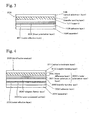
- Fig. 4 an identification medium 300 is shown.
- the identification medium 300 has a stacked structure, and in the stacked structure, a separator 301, an adhesive layer 302 (adhesive layer), a metal reflection layer 303, a hologram formed layer 305, a transfer bonding layer 306, a linear polarization layer 307, and a phase difference layer 308, a transfer bonding layer 310, and an optical anisotropic layer 311 are stacked from a side of the identification medium 300 on which an article is applied.
- a separator 301 an adhesive layer 302 (adhesive layer), a metal reflection layer 303, a hologram formed layer 305, a transfer bonding layer 306, a linear polarization layer 307, and a phase difference layer 308, a transfer bonding layer 310, and an optical anisotropic layer 311 are stacked from a side of the identification medium 300 on which an article is applied.
- the separator 301 is applied onto an exposed surface of the adhesive layer 302, and when the identification medium 300 is applied onto the article, the separator 301 is peeled from the adhesive layer 302.
- the adhesive layer 302 has a function for applying the identification medium 300 onto the article and fixing the identification medium 300 thereto.
- the metal reflection layer 303 is a vapor deposited layer made of A1 or the like.
- the hologram formed layer 305 is a transparent resin layer, and a side of the hologram formed layer 305 proximate to the metal reflection layer 303 is subjected to embossing process for formation of a hologram. The hologram image can be observed by evaporating the metal reflection layer 303 on the embossed structure.
- the transfer bonding layer 306 is a transparent layer bonding the hologram formed layer 305 and the linear polarization layer 307.
- the linear polarization layer 307 and the phase difference layer 308 form a circular polarization layer 309.
- the circular polarization layer 309 functions as a circular polarization filter allowing right circularly polarized light to selectively pass therethrough toward the observation surface side (the upper side in Fig. 4 ) when natural light enters from the lower side in Fig. 4 . That is, the linear polarization layer 307 is a layer of a linear polarization filter allowing linearly polarized light of specific direction to selectively pass therethrough.
- the phase difference layer 308 is a quarter wavelength plate.
- Directions of absorption axis of the linear polarization layer 307 and slow axis of the phase difference layer 308 are shifted 45 degrees from each other, so that right circularly polarized light selectively passes through the circular polarization layer 309 toward the upper side in Fig. 4 when natural light enters from the lower side in Fig. 4 .
- the polarized direction of the circularly polarized light, which selectively passes through the circular polarization layer 309 toward the upper side in Fig. 4 may be left. This selection of the polarized direction is performed by selecting directions of the absorption axis of the linear polarization layer 307 and the slow axis of the phase difference layer 308 which are shifted by 45 degrees.
- the transfer bonding layer 310 is a transparent layer which bonds the circular polarization layer 309 and the optical anisotropic layer 311.
- the optical anisotropic layer 311 is the same layer as the optical anisotropic layer 106 shown in Fig. 1 .
- the optical anisotropic layer 311 shown in Fig. 4 has the same optical anisotropic pattern shown in Fig. 2 (seen from the front surface) as the optical anisotropic layer 106 shown in Fig. 1 . That is, in the optical anisotropic layer 311, refractive indexes of perpendicular directions in a plane are different, and the areas A to C shown in Fig. 2 are different from each other in difference condition of refractive indexes.
- the area D is formed as a simple light transmission area having no anisotropy of refractive index.
- a film having a linear polarization layer 307 and a phase difference layer 308 which are applied to each other is made.
- a surface of a hologram formed layer 305 is subjected to an embossing process in advance, a vapor deposited film made of A1 is formed on the surface of thereof, and a metal reflection layer 303 having a hologram processed portion 304 is made.
- the hologram formed layer 305 having the metal reflection layer 303 is applied onto a side of the linear polarization layer 307 of the film, which has the linear polarization layer 307 and the phase difference layer 308, via a transfer bonding layer 306.
- An optical anisotropic layer 311 is fixed to the phase difference layer 308 of the film via a transfer bonding layer 310.
- the optical anisotropic layer 311 is made in the same manner as the optical anisotropic layer 106 as explained in the first embodiment, and one peeled from a base is used as the optical anisotropic layer 311. Finally, an adhesive layer 302 is formed, and a separator 301 is applied onto an exposed surface of the adhesive layer 302. Thus, an identification medium 300 shown in Fig. 4 is obtained.
- the observation of the identification medium 300 is performed from the upper side in Fig. 4 .
- a hologram image (not shown in the Figure) formed by the hologram processed portion 304 is seen.
- the characters of the areas A to C shown in Fig. 2 cannot be seen.
- the birefringence effect corresponding to the difference of the birefringence (difference of retardation value) of each of the areas A to C is provided to each of the areas A to C, and the colors of the areas A to C are seen so as to be different from each other.
- the reflection light of the right circularly polarized light is observed via the right circular polarization filter, so that reflection light having a metallic luster is seen, and the hologram image (not shown in the Figure) formed by the hologram processed portion 304 is simultaneously seen.
- the identification medium 300 is observed via a left circular polarization filter contacting an upper surface of the optical anisotropic layer 311 of the identification medium 300.
- the left circularly polarized light from the upper surface of the circular polarization layer 309 enters the identification medium 300.
- the incident light is blocked by the circular polarization layer 309, so that the portion of the area D appears to be black.
- a portion of component of light which is elliptically polarized light by the birefringence effect, passes through the circular polarization layer 309 from the upper side to the lower side in Fig. 4 , and the portion of component of light is reflected by the metal reflection layer 303.
- This reflection light passes through the circular polarization layer 309 in the upper direction shown in Fig. 4 , passes through the optical anisotropic layer 311 in the upper direction shown in Fig. 4 , and is observed via the left circular polarization filter.
- Each light from the areas A to C, which is observed via the left circular polarization filter, is caused to have the birefringence effect which is different at the areas A to C.
- the wavelengths of peaks of the lights from the areas A to C, which pass through the left circular polarization filter are different from each other, so that the lights from the areas A to C are observed to be different in color. In this manner, the hologram image cannot be approximately seen, and the areas A to B are observed in the black background so as to be different in color.
- the identification medium 300 is observed via a left circular polarization filter spaced away from the identification medium 300.
- natural light enters the circular polarization layer 309 from the upper side in Fig. 4 .
- the light which is reflected by the metal reflection layer 303 and enters the optical anisotropic layer 311 from the lower side in Fig. 4 , is mainly changed to right circular polarized light, and is partially changed to elliptically polarized light as an incident light which enters the areas A to C.
- the reflection light from the area D is right circular polarized light, thereby being blocked by the left circular polarization filter for observation.
- the portion of the area D appears to be black.
- the lights from portions of the areas A to C are caused to have the birefringence effect at the optical anisotropic layer 311.
- the lights from the portions of the areas A to C include a component of light passing through the left circular polarization filter, so that the colors of the portions of the areas A to C are seen depending on the birefringence effect at each of the areas A to C.
- the appearances of the identification medium 300 which are obtained when the circular polarization filter contacts the identification medium 300 and when the circular polarization filter is spaced away from the identification medium 300, are the same. This is because the light, which enters the optical anisotropic layer 311 from the lower side in Fig. 4 , is restricted to the right circularly polarized light by the function of the circular polarization layer 309. Since the circularly polarized light is used for observation, even when the circular polarization filter is rotated (or even when the identification medium 300 is reversely rotated), the observed feature is not changed. The characteristics are advantageous in obtaining stable identification function even when the observation manner is slightly rough.
- the stable identification function cannot be obtained depending the observation manner, and the possibility that precise determination of authenticity may not be performed may be increased. This is not desirable since the possibility that precise determination of authenticity may not be performed increases when determination of authenticity is performed by less-experienced users (consumers or the like).
- the optical identification function which is set in advance can be reliably observed, and the above problem can be reduced.
- the optical anisotropic layer 311 is exposed.
- a structure can be used in which the surface of the optical anisotropic layer 311 is covered with a transparent layer.
- the hologram processed portion 304 is a processed portion in which a diffraction grating is formed.
- a layer which is formed by adding at least one of iodine and dichroism pigment to PVA (polyvinyl alcohol) and stretching , a layer in which lyotropic liquid crystal is coated and oriented, a polarization layer of wire grid, or the like may be used as the linear polarization layer 307.
- a layer which is formed by stretching PC (polycarbonate) or COP (cycloolefin polymer), or a layer which is formed by orienting an anisotropic liquid crystal may be used as the phase difference layer 308.
- the optical anisotropic layer may be made from an optically transparent film pattern having birefringence.
- a process may be used in which an optically transparent film pattern having birefringence and a pattern shown in Fig. 2 is prepared, and the optically transparent film pattern is transferred to the easy peeling layer 105.
- the position of the hologram processed portion 103 may be one side of another surface of the cholesteric liquid crystal layer 102, or both surfaces of the cholesteric liquid crystal layer 102.
- the pattern shown in Fig. 2 is one example. Alternatively, a design or a pattern may be used.
- an area of the cholesteric liquid crystal layer is finely divided, and plural dotted cholesteric liquid crystal areas form a cholesteric liquid crystal layer.
- Plural dotted cholesteric liquid crystal areas are formed by injecting undiluted solution of cholesteric liquid crystal layer from a nozzle in the same manner as the ink-jet technique using a principle of ink-jet printer method, so that the cholesteric liquid crystal layer is formed.
- two kinds of undiluted solutions which are different from each other in included amount of chiral agent, are prepared as undiluted solutions of cholesteric liquid crystal, and first cholesteric liquid crystal areas and second cholesteric liquid crystal areas are formed in a checker board design.
- the two kinds of cholesteric liquid crystal areas have pitch widths of spiral structure, which are different from each other, depending on difference in the included amount of chiral agent.
- the center wavelength of reflection light may be determined by the pitch widths of the spiral structure of the cholesteric liquid crystal.
- the dotted areas of the cholesteric liquid crystal which selectively reflects lights of two kinds of center wavelengths different from each other, may be arranged in the checker board design, so that the regions of the wavelengths of light reflected from the entire cholesteric liquid crystal may be broadened.
- images of wider range of wavelength can be used for identification. For example, in observation using an optical filter, identification characteristics can be obtained in which the image of the area A appears to be red, and the image of the area C appears to be blue.
- cholesteric liquid crystal areas having two kinds of pitch widths are used and reflection lights of two kinds of center wavelengths are obtained.
- a structure may be used in which the number of different pitch widths is increased and lights of more kinds of center wavelengths are reflected.
- a structure may be used in which cholesteric liquid crystal areas having different plural kinds of pitch widths are arranged in a stripe manner.
- a liquid crystal ink in which cholesteric liquid crystal having different pitch widths is dispersed in an ink may be prepared, the liquid crystal ink may be coated, so that a reflection layer in which cholesteric liquid crystal phases reflecting lights of two center wavelengths are mixed may be formed.
- a structure may be used in which cholesteric liquid crystal layers reflecting three kinds of center wavelengths of RGB (red-green-blue) are stacked, and the wavelength region of reflection light may be broadened.
- birefringence may be also provided to the area D, and the color of the area D may be seen to be different from those of the areas A to C.
- the present invention can be applied to techniques used for determination of authenticity.
Applications Claiming Priority (2)
| Application Number | Priority Date | Filing Date | Title |
|---|---|---|---|
| JP2009270012 | 2009-11-27 | ||
| PCT/JP2010/070212 WO2011065242A1 (ja) | 2009-11-27 | 2010-11-12 | 識別媒体およびその識別方法 |
Publications (3)
| Publication Number | Publication Date |
|---|---|
| EP2506065A1 EP2506065A1 (en) | 2012-10-03 |
| EP2506065A4 EP2506065A4 (en) | 2013-07-03 |
| EP2506065B1 true EP2506065B1 (en) | 2015-04-29 |
Family
ID=44066347
Family Applications (1)
| Application Number | Title | Priority Date | Filing Date |
|---|---|---|---|
| EP10833089.5A Not-in-force EP2506065B1 (en) | 2009-11-27 | 2010-11-12 | Identification medium and identification method therefor |
Country Status (6)
| Country | Link |
|---|---|
| US (1) | US8970953B2 (zh) |
| EP (1) | EP2506065B1 (zh) |
| JP (1) | JP5462884B2 (zh) |
| KR (1) | KR101392614B1 (zh) |
| CN (1) | CN102667580A (zh) |
| WO (1) | WO2011065242A1 (zh) |
Families Citing this family (18)
| Publication number | Priority date | Publication date | Assignee | Title |
|---|---|---|---|---|
| WO2011092922A1 (ja) * | 2010-01-28 | 2011-08-04 | 日本発條株式会社 | 識別媒体およびその識別方法 |
| JP6065409B2 (ja) * | 2012-05-09 | 2017-01-25 | 凸版印刷株式会社 | 偽造防止媒体、偽造防止ステッカー、偽造防止転写箔及び検証方法 |
| JP6291712B2 (ja) * | 2013-02-27 | 2018-03-14 | 凸版印刷株式会社 | 偽造防止媒体及びその真贋判定方法 |
| JP2015069070A (ja) * | 2013-09-30 | 2015-04-13 | 凸版印刷株式会社 | 偽造防止用デバイスおよびその真偽判定方法 |
| CN106461847A (zh) * | 2014-06-30 | 2017-02-22 | 日本瑞翁株式会社 | 识别介质、识别介质的制造方法和识别介质的使用方法 |
| US20180217308A1 (en) * | 2014-09-05 | 2018-08-02 | Kolon Industries, Inc. | Security film |
| CN104385801B (zh) * | 2014-11-18 | 2017-01-25 | 浙江京华激光科技股份有限公司 | 一种用于纸质证件的微纳米全息防伪膜及生产工艺和应用 |
| WO2016188937A1 (en) * | 2015-05-26 | 2016-12-01 | Rolic Ag | Optical security device |
| AU2016267565B2 (en) * | 2015-05-26 | 2021-08-12 | Rolic Ag | Multiple hidden image security device |
| EP3364378A4 (en) * | 2015-10-08 | 2019-07-03 | Universidad Politécnica de Madrid | OPTICAL ELEMENT AND MANUFACTURING METHOD WITH MULTIPLE LATENT IMAGES FOR SECURITY OF DOCUMENTS |
| WO2017110225A1 (ja) * | 2015-12-25 | 2017-06-29 | Jxエネルギー株式会社 | 光学フィルム |
| JP6857384B2 (ja) | 2016-11-24 | 2021-04-14 | 国立大学法人大阪大学 | 光学素子 |
| WO2018212348A1 (ja) * | 2017-05-19 | 2018-11-22 | 富士フイルム株式会社 | 光学素子および光学装置 |
| CN110250667B (zh) * | 2019-06-28 | 2023-12-29 | 深圳市华圣达拉链有限公司 | 滤色拉链结构 |
| CN114981693A (zh) * | 2020-01-31 | 2022-08-30 | 日本瑞翁株式会社 | 识别介质、物品以及识别介质的使用方法 |
| KR20210138980A (ko) * | 2020-05-13 | 2021-11-22 | 엔비에스티(주) | 편광물질을 포함하는 위변조 방지수단 및 이의 활용방법 |
| CN117015730A (zh) * | 2021-03-30 | 2023-11-07 | 日本瑞翁株式会社 | 光学显示介质、物品以及光学显示介质的使用方法 |
| CN113147216B (zh) * | 2021-05-24 | 2022-09-13 | 中钞印制技术研究院有限公司 | 光学防伪元件及其检测、制造方法和装置、安全物品 |
Family Cites Families (32)
| Publication number | Priority date | Publication date | Assignee | Title |
|---|---|---|---|---|
| US5284364A (en) * | 1992-06-10 | 1994-02-08 | Anvik Corporation | Increased-security identification card system |
| JPH0968927A (ja) * | 1995-09-01 | 1997-03-11 | Nitto Denko Corp | 偽造防止方法及びそのラベル |
| CN1163765C (zh) * | 1997-05-09 | 2004-08-25 | 罗利克有限公司 | 光学元件和包含它的防伪或防拷贝元器件 |
| EP0911758B1 (en) | 1997-07-29 | 2005-11-30 | Nhk Spring Co.Ltd. | Optical identification system using cholesteric liquid crystals |
| JP3652487B2 (ja) | 1997-11-20 | 2005-05-25 | 日本発条株式会社 | 対象物の識別用媒体及び識別構造及び識別方法 |
| US6496287B1 (en) * | 1998-04-09 | 2002-12-17 | Rolic Ag | Optical identification element |
| WO2000013065A1 (en) * | 1998-08-27 | 2000-03-09 | Nippon Mitsubishi Oil Corporation | Genuineness detecting system and method for using genuineness detecting film |
| JP4335352B2 (ja) * | 1999-03-05 | 2009-09-30 | 大日本印刷株式会社 | 偽造防止体及び偽造判別方法 |
| US6344887B1 (en) * | 1999-09-10 | 2002-02-05 | Yao-Dong Ma | Full spectrum reflective choleterics display employing circular polarizers with the same polarity but different disposition |
| EP1120737A1 (en) * | 2000-01-27 | 2001-08-01 | Rolic AG | Optical security device |
| GB0201767D0 (en) * | 2002-01-25 | 2002-03-13 | Rue De Int Ltd | Improvements in methods of manufacturing substrates |
| JP2003231380A (ja) * | 2002-02-12 | 2003-08-19 | Nhk Spring Co Ltd | 対象物の識別媒体及び識別方法 |
| TWI258603B (en) * | 2002-04-23 | 2006-07-21 | Nitto Denko Corp | Polarized light device, polarized light source and image display apparatus using the same |
| JP4392826B2 (ja) * | 2003-05-16 | 2010-01-06 | 日本発條株式会社 | 対象物の識別媒体及び識別方法 |
| JP4257903B2 (ja) * | 2003-10-28 | 2009-04-30 | 日本発條株式会社 | 識別媒体、識別媒体の識別方法、識別対象物品および識別装置 |
| US20070081144A1 (en) * | 2003-12-26 | 2007-04-12 | Nhk Spring Co., Ltd. | Discrimination medium and discrimination method for discriminating the same |
| DE102004018702B4 (de) * | 2004-04-17 | 2006-05-24 | Leonhard Kurz Gmbh & Co. Kg | Folie mit Polymerschicht |
| JP4670470B2 (ja) * | 2005-05-16 | 2011-04-13 | 凸版印刷株式会社 | 隠蔽画像積層体およびその製造方法 |
| JP4909535B2 (ja) | 2005-06-23 | 2012-04-04 | 日東電工株式会社 | 積層反射体、認証カード、バーコードラベル、認証システム、及び、認証領域形成システム |
| JP4967415B2 (ja) * | 2006-03-31 | 2012-07-04 | 大日本印刷株式会社 | 真正性判定システム |
| JP4866129B2 (ja) | 2006-04-03 | 2012-02-01 | 日本発條株式会社 | 識別媒体、識別方法および識別装置 |
| JP5183165B2 (ja) * | 2006-11-21 | 2013-04-17 | 富士フイルム株式会社 | 複屈折パターンを有する物品の製造方法 |
| JP4959304B2 (ja) * | 2006-11-22 | 2012-06-20 | 日本発條株式会社 | 識別媒体、識別方法および識別装置 |
| JP4935328B2 (ja) | 2006-11-30 | 2012-05-23 | 凸版印刷株式会社 | 積層体、粘着ラベル、記録媒体、ラベル付き物品、検証具、キット及び判別方法 |
| JP5028642B2 (ja) * | 2006-11-30 | 2012-09-19 | 凸版印刷株式会社 | 積層体、粘着ラベル、記録媒体、ラベル付き物品及び判別方法 |
| JP5211474B2 (ja) | 2006-11-30 | 2013-06-12 | 凸版印刷株式会社 | 積層体、粘着ラベル、記録媒体及びラベル付き物品 |
| JP5227596B2 (ja) | 2008-01-22 | 2013-07-03 | 富士フイルム株式会社 | 複屈折パターンを有する物品の製造方法 |
| JP5245473B2 (ja) | 2008-03-13 | 2013-07-24 | 凸版印刷株式会社 | セキュリティデバイス及びラベル付き物品 |
| JP5380007B2 (ja) * | 2008-06-16 | 2014-01-08 | 富士フイルム株式会社 | 偽造防止媒体 |
| JP5361536B2 (ja) * | 2009-05-26 | 2013-12-04 | 富士フイルム株式会社 | 複屈折パターン認証用ビューワ、複屈折パターン認証用キット、真正性認証媒体、および真正性認証方法 |
| WO2011092922A1 (ja) * | 2010-01-28 | 2011-08-04 | 日本発條株式会社 | 識別媒体およびその識別方法 |
| JP5412350B2 (ja) * | 2010-03-26 | 2014-02-12 | 富士フイルム株式会社 | 複屈折パターンを有する物品 |
-
2010
- 2010-11-12 JP JP2011543210A patent/JP5462884B2/ja not_active Expired - Fee Related
- 2010-11-12 EP EP10833089.5A patent/EP2506065B1/en not_active Not-in-force
- 2010-11-12 KR KR1020127015742A patent/KR101392614B1/ko active IP Right Grant
- 2010-11-12 US US13/509,916 patent/US8970953B2/en not_active Expired - Fee Related
- 2010-11-12 WO PCT/JP2010/070212 patent/WO2011065242A1/ja active Application Filing
- 2010-11-12 CN CN2010800535069A patent/CN102667580A/zh active Pending
Also Published As
| Publication number | Publication date |
|---|---|
| JP5462884B2 (ja) | 2014-04-02 |
| JPWO2011065242A1 (ja) | 2013-04-11 |
| CN102667580A (zh) | 2012-09-12 |
| EP2506065A4 (en) | 2013-07-03 |
| KR20120094052A (ko) | 2012-08-23 |
| US20120236292A1 (en) | 2012-09-20 |
| WO2011065242A1 (ja) | 2011-06-03 |
| KR101392614B1 (ko) | 2014-05-07 |
| EP2506065A1 (en) | 2012-10-03 |
| WO2011065242A8 (ja) | 2012-05-10 |
| US8970953B2 (en) | 2015-03-03 |
Similar Documents
| Publication | Publication Date | Title |
|---|---|---|
| EP2506065B1 (en) | Identification medium and identification method therefor | |
| US8111352B2 (en) | Anisotropic optical device with varying local imagewise and method for making same | |
| CA2631161C (en) | Optical device, labeled article, optical kit and discrimination method | |
| KR101510919B1 (ko) | 식별 매체 및 그 제조 방법 | |
| CA2553980C (en) | Diffractive, polarization modulating optical devices | |
| JP5245296B2 (ja) | 偽造防止媒体および判別方法 | |
| US8168080B2 (en) | Identifying medium, identifying medium manufacturing method, article, and identifying medium identifying method | |
| JP5597940B2 (ja) | 表示体、粘着ラベル、転写箔及びラベル付き物品 | |
| JP5647047B2 (ja) | 識別媒体 | |
| JP5045328B2 (ja) | 光学素子、ラベル付き物品、光学キット及び判別方法 | |
| JP5380773B2 (ja) | 積層体、粘着ラベル、転写箔、記録媒体、ラベル付き物品、キット及び判別方法 | |
| JP6268941B2 (ja) | 偽造防止用デバイスおよびその製造方法 | |
| JP4978403B2 (ja) | 光学素子、ラベル付き物品、光学キット及び判別方法 | |
| JP5125418B2 (ja) | 光学素子、ラベル付き物品、光学キット及び判別方法 | |
| JP2005022292A (ja) | 対象物の識別構造およびその構造が設けられた対象物 | |
| WO2017204168A1 (ja) | 偽造防止媒体 | |
| JP5245473B2 (ja) | セキュリティデバイス及びラベル付き物品 | |
| JP5380791B2 (ja) | 光学素子、ラベル付き物品、光学キット及び判別方法 | |
| JP2011123257A (ja) | 識別媒体およびその識別方法 | |
| JP4286377B2 (ja) | コレステリック液晶性フィルムの製造方法 | |
| JP2013068701A (ja) | 偽造防止媒体及びその真贋判定方法並びに偽造防止媒体の製造方法 | |
| JP5141108B2 (ja) | 光学素子、ラベル付き物品、光学キット及び判別方法 |
Legal Events
| Date | Code | Title | Description |
|---|---|---|---|
| PUAI | Public reference made under article 153(3) epc to a published international application that has entered the european phase |
Free format text: ORIGINAL CODE: 0009012 |
|
| 17P | Request for examination filed |
Effective date: 20120627 |
|
| AK | Designated contracting states |
Kind code of ref document: A1 Designated state(s): AL AT BE BG CH CY CZ DE DK EE ES FI FR GB GR HR HU IE IS IT LI LT LU LV MC MK MT NL NO PL PT RO RS SE SI SK SM TR |
|
| DAX | Request for extension of the european patent (deleted) | ||
| A4 | Supplementary search report drawn up and despatched |
Effective date: 20130603 |
|
| RIC1 | Information provided on ipc code assigned before grant |
Ipc: B42D 15/10 20060101ALI20130527BHEP Ipc: G02F 1/13 20060101AFI20130527BHEP Ipc: B42D 15/00 20060101ALI20130527BHEP Ipc: G02F 1/13363 20060101ALI20130527BHEP Ipc: G02B 5/30 20060101ALI20130527BHEP |
|
| GRAP | Despatch of communication of intention to grant a patent |
Free format text: ORIGINAL CODE: EPIDOSNIGR1 |
|
| RIC1 | Information provided on ipc code assigned before grant |
Ipc: G02F 1/13 20060101AFI20140930BHEP Ipc: G02F 1/13363 20060101ALI20140930BHEP Ipc: B42D 15/00 20060101ALI20140930BHEP Ipc: G03H 1/02 20060101ALI20140930BHEP Ipc: G02B 5/30 20060101ALI20140930BHEP |
|
| INTG | Intention to grant announced |
Effective date: 20141023 |
|
| GRAS | Grant fee paid |
Free format text: ORIGINAL CODE: EPIDOSNIGR3 |
|
| GRAA | (expected) grant |
Free format text: ORIGINAL CODE: 0009210 |
|
| RAP1 | Party data changed (applicant data changed or rights of an application transferred) |
Owner name: NHK SPRING CO., LTD. |
|
| AK | Designated contracting states |
Kind code of ref document: B1 Designated state(s): AL AT BE BG CH CY CZ DE DK EE ES FI FR GB GR HR HU IE IS IT LI LT LU LV MC MK MT NL NO PL PT RO RS SE SI SK SM TR |
|
| REG | Reference to a national code |
Ref country code: GB Ref legal event code: FG4D |
|
| REG | Reference to a national code |
Ref country code: CH Ref legal event code: EP |
|
| REG | Reference to a national code |
Ref country code: AT Ref legal event code: REF Ref document number: 724755 Country of ref document: AT Kind code of ref document: T Effective date: 20150515 Ref country code: CH Ref legal event code: NV Representative=s name: RENTSCH PARTNER AG, CH |
|
| REG | Reference to a national code |
Ref country code: IE Ref legal event code: FG4D |
|
| REG | Reference to a national code |
Ref country code: DE Ref legal event code: R096 Ref document number: 602010024384 Country of ref document: DE Effective date: 20150611 |
|
| REG | Reference to a national code |
Ref country code: NL Ref legal event code: VDEP Effective date: 20150429 |
|
| REG | Reference to a national code |
Ref country code: AT Ref legal event code: MK05 Ref document number: 724755 Country of ref document: AT Kind code of ref document: T Effective date: 20150429 |
|
| REG | Reference to a national code |
Ref country code: LT Ref legal event code: MG4D |
|
| PG25 | Lapsed in a contracting state [announced via postgrant information from national office to epo] |
Ref country code: NL Free format text: LAPSE BECAUSE OF FAILURE TO SUBMIT A TRANSLATION OF THE DESCRIPTION OR TO PAY THE FEE WITHIN THE PRESCRIBED TIME-LIMIT Effective date: 20150429 |
|
| PG25 | Lapsed in a contracting state [announced via postgrant information from national office to epo] |
Ref country code: FI Free format text: LAPSE BECAUSE OF FAILURE TO SUBMIT A TRANSLATION OF THE DESCRIPTION OR TO PAY THE FEE WITHIN THE PRESCRIBED TIME-LIMIT Effective date: 20150429 Ref country code: HR Free format text: LAPSE BECAUSE OF FAILURE TO SUBMIT A TRANSLATION OF THE DESCRIPTION OR TO PAY THE FEE WITHIN THE PRESCRIBED TIME-LIMIT Effective date: 20150429 Ref country code: ES Free format text: LAPSE BECAUSE OF FAILURE TO SUBMIT A TRANSLATION OF THE DESCRIPTION OR TO PAY THE FEE WITHIN THE PRESCRIBED TIME-LIMIT Effective date: 20150429 Ref country code: LT Free format text: LAPSE BECAUSE OF FAILURE TO SUBMIT A TRANSLATION OF THE DESCRIPTION OR TO PAY THE FEE WITHIN THE PRESCRIBED TIME-LIMIT Effective date: 20150429 Ref country code: NO Free format text: LAPSE BECAUSE OF FAILURE TO SUBMIT A TRANSLATION OF THE DESCRIPTION OR TO PAY THE FEE WITHIN THE PRESCRIBED TIME-LIMIT Effective date: 20150729 |
|
| REG | Reference to a national code |
Ref country code: FR Ref legal event code: PLFP Year of fee payment: 6 |
|
| PG25 | Lapsed in a contracting state [announced via postgrant information from national office to epo] |
Ref country code: GR Free format text: LAPSE BECAUSE OF FAILURE TO SUBMIT A TRANSLATION OF THE DESCRIPTION OR TO PAY THE FEE WITHIN THE PRESCRIBED TIME-LIMIT Effective date: 20150730 Ref country code: LV Free format text: LAPSE BECAUSE OF FAILURE TO SUBMIT A TRANSLATION OF THE DESCRIPTION OR TO PAY THE FEE WITHIN THE PRESCRIBED TIME-LIMIT Effective date: 20150429 Ref country code: RS Free format text: LAPSE BECAUSE OF FAILURE TO SUBMIT A TRANSLATION OF THE DESCRIPTION OR TO PAY THE FEE WITHIN THE PRESCRIBED TIME-LIMIT Effective date: 20150429 Ref country code: AT Free format text: LAPSE BECAUSE OF FAILURE TO SUBMIT A TRANSLATION OF THE DESCRIPTION OR TO PAY THE FEE WITHIN THE PRESCRIBED TIME-LIMIT Effective date: 20150429 Ref country code: IS Free format text: LAPSE BECAUSE OF FAILURE TO SUBMIT A TRANSLATION OF THE DESCRIPTION OR TO PAY THE FEE WITHIN THE PRESCRIBED TIME-LIMIT Effective date: 20150829 |
|
| PG25 | Lapsed in a contracting state [announced via postgrant information from national office to epo] |
Ref country code: DK Free format text: LAPSE BECAUSE OF FAILURE TO SUBMIT A TRANSLATION OF THE DESCRIPTION OR TO PAY THE FEE WITHIN THE PRESCRIBED TIME-LIMIT Effective date: 20150429 Ref country code: EE Free format text: LAPSE BECAUSE OF FAILURE TO SUBMIT A TRANSLATION OF THE DESCRIPTION OR TO PAY THE FEE WITHIN THE PRESCRIBED TIME-LIMIT Effective date: 20150429 |
|
| REG | Reference to a national code |
Ref country code: DE Ref legal event code: R097 Ref document number: 602010024384 Country of ref document: DE |
|
| PG25 | Lapsed in a contracting state [announced via postgrant information from national office to epo] |
Ref country code: CZ Free format text: LAPSE BECAUSE OF FAILURE TO SUBMIT A TRANSLATION OF THE DESCRIPTION OR TO PAY THE FEE WITHIN THE PRESCRIBED TIME-LIMIT Effective date: 20150429 Ref country code: PL Free format text: LAPSE BECAUSE OF FAILURE TO SUBMIT A TRANSLATION OF THE DESCRIPTION OR TO PAY THE FEE WITHIN THE PRESCRIBED TIME-LIMIT Effective date: 20150429 Ref country code: RO Free format text: LAPSE BECAUSE OF NON-PAYMENT OF DUE FEES Effective date: 20150429 Ref country code: SK Free format text: LAPSE BECAUSE OF FAILURE TO SUBMIT A TRANSLATION OF THE DESCRIPTION OR TO PAY THE FEE WITHIN THE PRESCRIBED TIME-LIMIT Effective date: 20150429 |
|
| PLBE | No opposition filed within time limit |
Free format text: ORIGINAL CODE: 0009261 |
|
| STAA | Information on the status of an ep patent application or granted ep patent |
Free format text: STATUS: NO OPPOSITION FILED WITHIN TIME LIMIT |
|
| 26N | No opposition filed |
Effective date: 20160201 |
|
| PG25 | Lapsed in a contracting state [announced via postgrant information from national office to epo] |
Ref country code: IT Free format text: LAPSE BECAUSE OF FAILURE TO SUBMIT A TRANSLATION OF THE DESCRIPTION OR TO PAY THE FEE WITHIN THE PRESCRIBED TIME-LIMIT Effective date: 20150429 |
|
| PG25 | Lapsed in a contracting state [announced via postgrant information from national office to epo] |
Ref country code: SI Free format text: LAPSE BECAUSE OF FAILURE TO SUBMIT A TRANSLATION OF THE DESCRIPTION OR TO PAY THE FEE WITHIN THE PRESCRIBED TIME-LIMIT Effective date: 20150429 |
|
| PG25 | Lapsed in a contracting state [announced via postgrant information from national office to epo] |
Ref country code: LU Free format text: LAPSE BECAUSE OF FAILURE TO SUBMIT A TRANSLATION OF THE DESCRIPTION OR TO PAY THE FEE WITHIN THE PRESCRIBED TIME-LIMIT Effective date: 20151112 Ref country code: MC Free format text: LAPSE BECAUSE OF FAILURE TO SUBMIT A TRANSLATION OF THE DESCRIPTION OR TO PAY THE FEE WITHIN THE PRESCRIBED TIME-LIMIT Effective date: 20150429 |
|
| REG | Reference to a national code |
Ref country code: IE Ref legal event code: MM4A |
|
| PG25 | Lapsed in a contracting state [announced via postgrant information from national office to epo] |
Ref country code: BE Free format text: LAPSE BECAUSE OF FAILURE TO SUBMIT A TRANSLATION OF THE DESCRIPTION OR TO PAY THE FEE WITHIN THE PRESCRIBED TIME-LIMIT Effective date: 20150429 |
|
| REG | Reference to a national code |
Ref country code: FR Ref legal event code: PLFP Year of fee payment: 7 |
|
| PG25 | Lapsed in a contracting state [announced via postgrant information from national office to epo] |
Ref country code: IE Free format text: LAPSE BECAUSE OF NON-PAYMENT OF DUE FEES Effective date: 20151112 |
|
| PG25 | Lapsed in a contracting state [announced via postgrant information from national office to epo] |
Ref country code: SM Free format text: LAPSE BECAUSE OF FAILURE TO SUBMIT A TRANSLATION OF THE DESCRIPTION OR TO PAY THE FEE WITHIN THE PRESCRIBED TIME-LIMIT Effective date: 20150429 Ref country code: BG Free format text: LAPSE BECAUSE OF FAILURE TO SUBMIT A TRANSLATION OF THE DESCRIPTION OR TO PAY THE FEE WITHIN THE PRESCRIBED TIME-LIMIT Effective date: 20150429 Ref country code: HU Free format text: LAPSE BECAUSE OF FAILURE TO SUBMIT A TRANSLATION OF THE DESCRIPTION OR TO PAY THE FEE WITHIN THE PRESCRIBED TIME-LIMIT; INVALID AB INITIO Effective date: 20101112 |
|
| PG25 | Lapsed in a contracting state [announced via postgrant information from national office to epo] |
Ref country code: CY Free format text: LAPSE BECAUSE OF FAILURE TO SUBMIT A TRANSLATION OF THE DESCRIPTION OR TO PAY THE FEE WITHIN THE PRESCRIBED TIME-LIMIT Effective date: 20150429 Ref country code: SE Free format text: LAPSE BECAUSE OF FAILURE TO SUBMIT A TRANSLATION OF THE DESCRIPTION OR TO PAY THE FEE WITHIN THE PRESCRIBED TIME-LIMIT Effective date: 20150429 |
|
| PG25 | Lapsed in a contracting state [announced via postgrant information from national office to epo] |
Ref country code: MT Free format text: LAPSE BECAUSE OF FAILURE TO SUBMIT A TRANSLATION OF THE DESCRIPTION OR TO PAY THE FEE WITHIN THE PRESCRIBED TIME-LIMIT Effective date: 20150429 |
|
| REG | Reference to a national code |
Ref country code: CH Ref legal event code: PCAR Free format text: NEW ADDRESS: BELLERIVESTRASSE 203 POSTFACH, 8034 ZUERICH (CH) |
|
| REG | Reference to a national code |
Ref country code: FR Ref legal event code: PLFP Year of fee payment: 8 |
|
| PG25 | Lapsed in a contracting state [announced via postgrant information from national office to epo] |
Ref country code: TR Free format text: LAPSE BECAUSE OF FAILURE TO SUBMIT A TRANSLATION OF THE DESCRIPTION OR TO PAY THE FEE WITHIN THE PRESCRIBED TIME-LIMIT Effective date: 20150429 Ref country code: MK Free format text: LAPSE BECAUSE OF FAILURE TO SUBMIT A TRANSLATION OF THE DESCRIPTION OR TO PAY THE FEE WITHIN THE PRESCRIBED TIME-LIMIT Effective date: 20150429 Ref country code: PT Free format text: LAPSE BECAUSE OF FAILURE TO SUBMIT A TRANSLATION OF THE DESCRIPTION OR TO PAY THE FEE WITHIN THE PRESCRIBED TIME-LIMIT Effective date: 20150429 |
|
| REG | Reference to a national code |
Ref country code: FR Ref legal event code: PLFP Year of fee payment: 9 |
|
| PG25 | Lapsed in a contracting state [announced via postgrant information from national office to epo] |
Ref country code: AL Free format text: LAPSE BECAUSE OF FAILURE TO SUBMIT A TRANSLATION OF THE DESCRIPTION OR TO PAY THE FEE WITHIN THE PRESCRIBED TIME-LIMIT Effective date: 20150429 |
|
| PGFP | Annual fee paid to national office [announced via postgrant information from national office to epo] |
Ref country code: DE Payment date: 20191029 Year of fee payment: 10 |
|
| PGFP | Annual fee paid to national office [announced via postgrant information from national office to epo] |
Ref country code: FR Payment date: 20191015 Year of fee payment: 10 |
|
| PGFP | Annual fee paid to national office [announced via postgrant information from national office to epo] |
Ref country code: CH Payment date: 20191116 Year of fee payment: 10 |
|
| PGFP | Annual fee paid to national office [announced via postgrant information from national office to epo] |
Ref country code: GB Payment date: 20191107 Year of fee payment: 10 |
|
| REG | Reference to a national code |
Ref country code: DE Ref legal event code: R119 Ref document number: 602010024384 Country of ref document: DE |
|
| REG | Reference to a national code |
Ref country code: CH Ref legal event code: PL |
|
| GBPC | Gb: european patent ceased through non-payment of renewal fee |
Effective date: 20201112 |
|
| PG25 | Lapsed in a contracting state [announced via postgrant information from national office to epo] |
Ref country code: LI Free format text: LAPSE BECAUSE OF NON-PAYMENT OF DUE FEES Effective date: 20201130 Ref country code: CH Free format text: LAPSE BECAUSE OF NON-PAYMENT OF DUE FEES Effective date: 20201130 |
|
| PG25 | Lapsed in a contracting state [announced via postgrant information from national office to epo] |
Ref country code: FR Free format text: LAPSE BECAUSE OF NON-PAYMENT OF DUE FEES Effective date: 20201130 |
|
| PG25 | Lapsed in a contracting state [announced via postgrant information from national office to epo] |
Ref country code: GB Free format text: LAPSE BECAUSE OF NON-PAYMENT OF DUE FEES Effective date: 20201112 Ref country code: DE Free format text: LAPSE BECAUSE OF NON-PAYMENT OF DUE FEES Effective date: 20210601 |