WO2011065242A1 - 識別媒体およびその識別方法 - Google Patents
識別媒体およびその識別方法 Download PDFInfo
- Publication number
- WO2011065242A1 WO2011065242A1 PCT/JP2010/070212 JP2010070212W WO2011065242A1 WO 2011065242 A1 WO2011065242 A1 WO 2011065242A1 JP 2010070212 W JP2010070212 W JP 2010070212W WO 2011065242 A1 WO2011065242 A1 WO 2011065242A1
- Authority
- WO
- WIPO (PCT)
- Prior art keywords
- layer
- identification medium
- light
- identification
- liquid crystal
- Prior art date
Links
- 238000000034 method Methods 0.000 title claims description 20
- 230000010287 polarization Effects 0.000 claims abstract description 90
- 239000004986 Cholesteric liquid crystals (ChLC) Substances 0.000 claims abstract description 56
- 230000003287 optical effect Effects 0.000 claims abstract description 44
- 229910052751 metal Inorganic materials 0.000 claims description 27
- 239000002184 metal Substances 0.000 claims description 27
- 238000012545 processing Methods 0.000 claims description 16
- 239000003086 colorant Substances 0.000 abstract description 18
- 230000000694 effects Effects 0.000 abstract description 18
- 239000010410 layer Substances 0.000 description 236
- 239000012790 adhesive layer Substances 0.000 description 27
- 230000008859 change Effects 0.000 description 11
- 239000000463 material Substances 0.000 description 11
- 238000012546 transfer Methods 0.000 description 11
- 239000004973 liquid crystal related substance Substances 0.000 description 8
- 239000010408 film Substances 0.000 description 6
- 238000004519 manufacturing process Methods 0.000 description 6
- 239000011295 pitch Substances 0.000 description 6
- 229920000642 polymer Polymers 0.000 description 6
- 239000000853 adhesive Substances 0.000 description 4
- 230000001070 adhesive effect Effects 0.000 description 4
- 229910052782 aluminium Inorganic materials 0.000 description 4
- XAGFODPZIPBFFR-UHFFFAOYSA-N aluminium Chemical compound [Al] XAGFODPZIPBFFR-UHFFFAOYSA-N 0.000 description 4
- 230000008901 benefit Effects 0.000 description 4
- 150000001875 compounds Chemical class 0.000 description 4
- ZWEHNKRNPOVVGH-UHFFFAOYSA-N 2-Butanone Chemical compound CCC(C)=O ZWEHNKRNPOVVGH-UHFFFAOYSA-N 0.000 description 3
- 230000005540 biological transmission Effects 0.000 description 3
- 238000010438 heat treatment Methods 0.000 description 3
- UWCWUCKPEYNDNV-LBPRGKRZSA-N 2,6-dimethyl-n-[[(2s)-pyrrolidin-2-yl]methyl]aniline Chemical compound CC1=CC=CC(C)=C1NC[C@H]1NCCC1 UWCWUCKPEYNDNV-LBPRGKRZSA-N 0.000 description 2
- 229920002284 Cellulose triacetate Polymers 0.000 description 2
- 239000004372 Polyvinyl alcohol Substances 0.000 description 2
- NNLVGZFZQQXQNW-ADJNRHBOSA-N [(2r,3r,4s,5r,6s)-4,5-diacetyloxy-3-[(2s,3r,4s,5r,6r)-3,4,5-triacetyloxy-6-(acetyloxymethyl)oxan-2-yl]oxy-6-[(2r,3r,4s,5r,6s)-4,5,6-triacetyloxy-2-(acetyloxymethyl)oxan-3-yl]oxyoxan-2-yl]methyl acetate Chemical compound O([C@@H]1O[C@@H]([C@H]([C@H](OC(C)=O)[C@H]1OC(C)=O)O[C@H]1[C@@H]([C@@H](OC(C)=O)[C@H](OC(C)=O)[C@@H](COC(C)=O)O1)OC(C)=O)COC(=O)C)[C@@H]1[C@@H](COC(C)=O)O[C@@H](OC(C)=O)[C@H](OC(C)=O)[C@H]1OC(C)=O NNLVGZFZQQXQNW-ADJNRHBOSA-N 0.000 description 2
- 238000010521 absorption reaction Methods 0.000 description 2
- 239000007822 coupling agent Substances 0.000 description 2
- 238000004132 cross linking Methods 0.000 description 2
- 230000005865 ionizing radiation Effects 0.000 description 2
- 230000031700 light absorption Effects 0.000 description 2
- 239000004417 polycarbonate Substances 0.000 description 2
- 238000006116 polymerization reaction Methods 0.000 description 2
- 229920002451 polyvinyl alcohol Polymers 0.000 description 2
- 230000008569 process Effects 0.000 description 2
- 239000000243 solution Substances 0.000 description 2
- 238000001228 spectrum Methods 0.000 description 2
- 239000011550 stock solution Substances 0.000 description 2
- 238000007740 vapor deposition Methods 0.000 description 2
- ZCYVEMRRCGMTRW-UHFFFAOYSA-N 7553-56-2 Chemical compound [I] ZCYVEMRRCGMTRW-UHFFFAOYSA-N 0.000 description 1
- 229920002799 BoPET Polymers 0.000 description 1
- 229920000089 Cyclic olefin copolymer Polymers 0.000 description 1
- 239000004976 Lyotropic liquid crystal Substances 0.000 description 1
- 238000013459 approach Methods 0.000 description 1
- 238000012663 cationic photopolymerization Methods 0.000 description 1
- 238000006243 chemical reaction Methods 0.000 description 1
- 239000003795 chemical substances by application Substances 0.000 description 1
- 239000011248 coating agent Substances 0.000 description 1
- 238000000576 coating method Methods 0.000 description 1
- 230000007423 decrease Effects 0.000 description 1
- 238000000151 deposition Methods 0.000 description 1
- 238000013461 design Methods 0.000 description 1
- 238000009826 distribution Methods 0.000 description 1
- 239000003999 initiator Substances 0.000 description 1
- 238000007641 inkjet printing Methods 0.000 description 1
- 229910052740 iodine Inorganic materials 0.000 description 1
- 239000011630 iodine Substances 0.000 description 1
- 238000010030 laminating Methods 0.000 description 1
- 239000002932 luster Substances 0.000 description 1
- 238000001465 metallisation Methods 0.000 description 1
- 239000000203 mixture Substances 0.000 description 1
- 230000004048 modification Effects 0.000 description 1
- 238000012986 modification Methods 0.000 description 1
- 239000000178 monomer Substances 0.000 description 1
- 239000012466 permeate Substances 0.000 description 1
- 239000000049 pigment Substances 0.000 description 1
- 229920000515 polycarbonate Polymers 0.000 description 1
- 239000002861 polymer material Substances 0.000 description 1
- 239000011241 protective layer Substances 0.000 description 1
- 239000011347 resin Substances 0.000 description 1
- 229920005989 resin Polymers 0.000 description 1
- 239000005268 rod-like liquid crystal Substances 0.000 description 1
- 230000003595 spectral effect Effects 0.000 description 1
- 239000010409 thin film Substances 0.000 description 1
Images


Classifications
-
- B—PERFORMING OPERATIONS; TRANSPORTING
- B42—BOOKBINDING; ALBUMS; FILES; SPECIAL PRINTED MATTER
- B42D—BOOKS; BOOK COVERS; LOOSE LEAVES; PRINTED MATTER CHARACTERISED BY IDENTIFICATION OR SECURITY FEATURES; PRINTED MATTER OF SPECIAL FORMAT OR STYLE NOT OTHERWISE PROVIDED FOR; DEVICES FOR USE THEREWITH AND NOT OTHERWISE PROVIDED FOR; MOVABLE-STRIP WRITING OR READING APPARATUS
- B42D25/00—Information-bearing cards or sheet-like structures characterised by identification or security features; Manufacture thereof
- B42D25/30—Identification or security features, e.g. for preventing forgery
- B42D25/36—Identification or security features, e.g. for preventing forgery comprising special materials
- B42D25/364—Liquid crystals
-
- G—PHYSICS
- G02—OPTICS
- G02B—OPTICAL ELEMENTS, SYSTEMS OR APPARATUS
- G02B5/00—Optical elements other than lenses
- G02B5/30—Polarising elements
-
- B—PERFORMING OPERATIONS; TRANSPORTING
- B42—BOOKBINDING; ALBUMS; FILES; SPECIAL PRINTED MATTER
- B42D—BOOKS; BOOK COVERS; LOOSE LEAVES; PRINTED MATTER CHARACTERISED BY IDENTIFICATION OR SECURITY FEATURES; PRINTED MATTER OF SPECIAL FORMAT OR STYLE NOT OTHERWISE PROVIDED FOR; DEVICES FOR USE THEREWITH AND NOT OTHERWISE PROVIDED FOR; MOVABLE-STRIP WRITING OR READING APPARATUS
- B42D15/00—Printed matter of special format or style not otherwise provided for
-
- B—PERFORMING OPERATIONS; TRANSPORTING
- B42—BOOKBINDING; ALBUMS; FILES; SPECIAL PRINTED MATTER
- B42D—BOOKS; BOOK COVERS; LOOSE LEAVES; PRINTED MATTER CHARACTERISED BY IDENTIFICATION OR SECURITY FEATURES; PRINTED MATTER OF SPECIAL FORMAT OR STYLE NOT OTHERWISE PROVIDED FOR; DEVICES FOR USE THEREWITH AND NOT OTHERWISE PROVIDED FOR; MOVABLE-STRIP WRITING OR READING APPARATUS
- B42D25/00—Information-bearing cards or sheet-like structures characterised by identification or security features; Manufacture thereof
- B42D25/20—Information-bearing cards or sheet-like structures characterised by identification or security features; Manufacture thereof characterised by a particular use or purpose
- B42D25/29—Securities; Bank notes
-
- B—PERFORMING OPERATIONS; TRANSPORTING
- B42—BOOKBINDING; ALBUMS; FILES; SPECIAL PRINTED MATTER
- B42D—BOOKS; BOOK COVERS; LOOSE LEAVES; PRINTED MATTER CHARACTERISED BY IDENTIFICATION OR SECURITY FEATURES; PRINTED MATTER OF SPECIAL FORMAT OR STYLE NOT OTHERWISE PROVIDED FOR; DEVICES FOR USE THEREWITH AND NOT OTHERWISE PROVIDED FOR; MOVABLE-STRIP WRITING OR READING APPARATUS
- B42D25/00—Information-bearing cards or sheet-like structures characterised by identification or security features; Manufacture thereof
- B42D25/30—Identification or security features, e.g. for preventing forgery
- B42D25/328—Diffraction gratings; Holograms
-
- G—PHYSICS
- G02—OPTICS
- G02B—OPTICAL ELEMENTS, SYSTEMS OR APPARATUS
- G02B5/00—Optical elements other than lenses
- G02B5/30—Polarising elements
- G02B5/3016—Polarising elements involving passive liquid crystal elements
-
- G—PHYSICS
- G02—OPTICS
- G02F—OPTICAL DEVICES OR ARRANGEMENTS FOR THE CONTROL OF LIGHT BY MODIFICATION OF THE OPTICAL PROPERTIES OF THE MEDIA OF THE ELEMENTS INVOLVED THEREIN; NON-LINEAR OPTICS; FREQUENCY-CHANGING OF LIGHT; OPTICAL LOGIC ELEMENTS; OPTICAL ANALOGUE/DIGITAL CONVERTERS
- G02F1/00—Devices or arrangements for the control of the intensity, colour, phase, polarisation or direction of light arriving from an independent light source, e.g. switching, gating or modulating; Non-linear optics
- G02F1/01—Devices or arrangements for the control of the intensity, colour, phase, polarisation or direction of light arriving from an independent light source, e.g. switching, gating or modulating; Non-linear optics for the control of the intensity, phase, polarisation or colour
- G02F1/13—Devices or arrangements for the control of the intensity, colour, phase, polarisation or direction of light arriving from an independent light source, e.g. switching, gating or modulating; Non-linear optics for the control of the intensity, phase, polarisation or colour based on liquid crystals, e.g. single liquid crystal display cells
- G02F1/133—Constructional arrangements; Operation of liquid crystal cells; Circuit arrangements
- G02F1/1333—Constructional arrangements; Manufacturing methods
- G02F1/1335—Structural association of cells with optical devices, e.g. polarisers or reflectors
- G02F1/13363—Birefringent elements, e.g. for optical compensation
-
- G—PHYSICS
- G03—PHOTOGRAPHY; CINEMATOGRAPHY; ANALOGOUS TECHNIQUES USING WAVES OTHER THAN OPTICAL WAVES; ELECTROGRAPHY; HOLOGRAPHY
- G03H—HOLOGRAPHIC PROCESSES OR APPARATUS
- G03H1/00—Holographic processes or apparatus using light, infrared or ultraviolet waves for obtaining holograms or for obtaining an image from them; Details peculiar thereto
- G03H1/02—Details of features involved during the holographic process; Replication of holograms without interference recording
- G03H1/0252—Laminate comprising a hologram layer
- G03H1/0256—Laminate comprising a hologram layer having specific functional layer
-
- B42D2033/10—
-
- B42D2033/26—
-
- B42D2035/24—
-
- B—PERFORMING OPERATIONS; TRANSPORTING
- B42—BOOKBINDING; ALBUMS; FILES; SPECIAL PRINTED MATTER
- B42D—BOOKS; BOOK COVERS; LOOSE LEAVES; PRINTED MATTER CHARACTERISED BY IDENTIFICATION OR SECURITY FEATURES; PRINTED MATTER OF SPECIAL FORMAT OR STYLE NOT OTHERWISE PROVIDED FOR; DEVICES FOR USE THEREWITH AND NOT OTHERWISE PROVIDED FOR; MOVABLE-STRIP WRITING OR READING APPARATUS
- B42D25/00—Information-bearing cards or sheet-like structures characterised by identification or security features; Manufacture thereof
- B42D25/30—Identification or security features, e.g. for preventing forgery
- B42D25/36—Identification or security features, e.g. for preventing forgery comprising special materials
- B42D25/378—Special inks
- B42D25/391—Special inks absorbing or reflecting polarised light
-
- G—PHYSICS
- G03—PHOTOGRAPHY; CINEMATOGRAPHY; ANALOGOUS TECHNIQUES USING WAVES OTHER THAN OPTICAL WAVES; ELECTROGRAPHY; HOLOGRAPHY
- G03H—HOLOGRAPHIC PROCESSES OR APPARATUS
- G03H1/00—Holographic processes or apparatus using light, infrared or ultraviolet waves for obtaining holograms or for obtaining an image from them; Details peculiar thereto
- G03H1/02—Details of features involved during the holographic process; Replication of holograms without interference recording
- G03H1/024—Hologram nature or properties
- G03H1/0244—Surface relief holograms
-
- G—PHYSICS
- G03—PHOTOGRAPHY; CINEMATOGRAPHY; ANALOGOUS TECHNIQUES USING WAVES OTHER THAN OPTICAL WAVES; ELECTROGRAPHY; HOLOGRAPHY
- G03H—HOLOGRAPHIC PROCESSES OR APPARATUS
- G03H2250/00—Laminate comprising a hologram layer
- G03H2250/14—Forming layer onto which a surface relief hologram is formed
-
- G—PHYSICS
- G03—PHOTOGRAPHY; CINEMATOGRAPHY; ANALOGOUS TECHNIQUES USING WAVES OTHER THAN OPTICAL WAVES; ELECTROGRAPHY; HOLOGRAPHY
- G03H—HOLOGRAPHIC PROCESSES OR APPARATUS
- G03H2250/00—Laminate comprising a hologram layer
- G03H2250/36—Conform enhancement layer
-
- G—PHYSICS
- G03—PHOTOGRAPHY; CINEMATOGRAPHY; ANALOGOUS TECHNIQUES USING WAVES OTHER THAN OPTICAL WAVES; ELECTROGRAPHY; HOLOGRAPHY
- G03H—HOLOGRAPHIC PROCESSES OR APPARATUS
- G03H2250/00—Laminate comprising a hologram layer
- G03H2250/38—Liquid crystal
Definitions
- the present invention relates to an identification medium and an identification method thereof.
- Patent Document 1 describes an identification medium in which a cholesteric liquid crystal layer is subjected to hologram processing.
- Patent Document 2 describes an identification medium on which a latent image is observed in observation through a polarizing filter by laminating a retardation layer on a reflective layer and partially changing the phase difference by heat.
- Patent Document 3 describes an identification medium in which latent images of different colors are observed in observation through a polarizing filter by providing regions having different phase differences.
- an image of a specific color can be used for identification.
- a plurality of color images for example, red and green images
- the polarizing filter when the polarizing filter is separated from the identification medium, light in various phase states is incident on the identification medium. Therefore, the selectivity of the reflection wavelength by the retardation layer (the light of a specific wavelength is reflected). The property of selectively transmitting through the retardation layer) and the specific polarization of the transmitted light are weakened, and the visually recognized image and its color become unclear. For this reason, since the identification function cannot be obtained unless the polarizing filter is brought into contact with or close to the identification medium, the application is limited.
- an object of the present invention is to provide an identification medium capable of observing a latent image having a plurality of colors even when the polarizing filter is separated from the identification medium.
- the invention according to claim 1 is an optical anisotropy disposed in a position overlapping with the specific polarization reflection layer that reflects light in a specific polarization state and the specific polarization reflection layer, and having optical anisotropy in a plane.
- the optically anisotropic layer is provided with a first image composed of a region having an optical anisotropy different from that of the other region.
- the light in a specific polarization state among the light incident on the identification medium is reflected from the specific polarization reflection layer.
- the specific polarization state is linearly polarized light having an amplitude component in a specific direction, right-handed circularly polarized light, and left-handed circularly polarized light.
- a cholesteric liquid crystal layer is employed as the specific polarization reflection layer.
- circularly polarized light having a specific center wavelength and having a specific turning direction is reflected from the cholesteric liquid crystal layer.
- the reflected light passes through the optically anisotropic layer and is emitted as reflected light from the identification medium to the outside of the identification medium.
- the polarization state changes to elliptically polarized light due to the birefringence effect (linear as the extreme value of this elliptically polarized light). Polarized light).
- the difference in polarization state cannot be recognized by the human eye, so the change in the polarization state due to the optically anisotropic layer is not observed, and the reflected light from the underlying cholesteric liquid crystal layer is observed.
- the first image is not observed (or difficult to observe).
- the cholesteric liquid crystal layer selectively reflects right-handed circularly polarized light
- the identification medium is observed through a right-handed circularly polarizing filter that selectively transmits right-handed circularly polarized light
- the right-handed circularly polarized light component Are selectively observed.
- the polarization state of the light transmitted through the first image portion of the optically anisotropic layer is changed by the birefringence effect. Therefore, the light that has passed through the first image portion of the optically anisotropic layer also includes polarization components other than right-handed circularly polarized light.
- This change in the polarization state is caused by the difference in refractive index in the in-plane orthogonal direction of the optically anisotropic layer, and has a wavelength dependency. Therefore, the difference in polarization state caused by passing through the optically anisotropic layer affects the wavelength distribution (wavelength spectrum) of the polarized light when a specific polarized light is selectively viewed.
- the degree of change in the polarization state given by the optically anisotropic layer is transmitted. It looks like a color according to. Therefore, the first image looks different from the surrounding color.
- the identification medium when the identification medium is observed through a circularly polarizing filter that selectively transmits circularly polarized light in the direction opposite to the above, the circularly polarized component in the direction opposite to the above case is observed.
- the first image can be seen in a color different from the above case.
- the first image that was not observed in the direct observation is observed in the observation through the right circular polarizing filter and the observation through the left circular polarizing filter, and different colors are obtained when the left and right circular polarizing filters are used.
- the latent image effect can be obtained.
- the base of the optically anisotropic layer is just a reflective surface (for example, a metal reflective layer)
- the polarization of the light incident on the identification medium is eliminated.
- the polarization of the light incident on the optically anisotropic layer from the ground is also eliminated.
- the polarization state of the light observed by the observer after passing through the optically anisotropic layer becomes close to natural light.
- the wavelength dependency of the polarization state decreases. For this reason, even if it observes through a polarizing filter, it becomes difficult to recognize the difference in wavelength (color difference) depending on a specific polarization state. That is, when the polarizing filter is separated from the identification medium, the optical function of the identification medium is lowered, and finally the identification function cannot be obtained.
- the same optical function as when the cholesteric liquid crystal layer is used as the specific polarization reflection layer can be obtained even when a configuration in which a metal reflection layer and a linear polarization filter layer are stacked as the specific polarization reflection layer.
- linearly polarized light polarized in a specific direction is reflected from the specific polarization reflection layer.
- This linearly polarized light becomes elliptically polarized light when passing through the optically anisotropic layer.
- the number of images may be plural.
- by using a plurality of images so that different phase differences occur in each image it is possible to simultaneously observe latent images having different colors.
- Examples of the image include characters, figures, backgrounds, and various patterns.
- regions having different optical anisotropy may be included in the image.
- the invention according to claim 1 can provide the same identification function even when the polarizing filter for observation is brought close to or in contact with the identification medium. That is, according to the first aspect of the present invention, it is possible to obtain an identification function capable of observing different color displays as latent images even when the polarizing filter for observation is brought into contact with the identification medium or separated from the identification medium.
- the invention according to claim 2 is the invention according to claim 1, wherein the specific polarization reflection layer is a cholesteric liquid crystal layer.
- the invention according to claim 3 is characterized in that the specific polarization reflection layer has a structure in which a metal reflection layer and an optical filter layer that selectively transmits linearly polarized light in a specific direction are laminated.
- the invention according to claim 4 is the invention according to claim 1, wherein the specific polarization reflection layer is a circular reflection of a specific turning direction when natural light is incident on the metal reflection layer and the observation surface side. It has the structure which laminated
- other layers such as an adhesive layer may or may not be interposed therebetween.
- the invention described in claim 5 is characterized in that, in the invention described in any one of claims 1 to 4, a hologram processing is applied to the specific polarization reflection layer.
- Holograms using reflected light from cholesteric liquid crystals have the advantage of being difficult to forge.
- embossed hologram processing with a reflective layer such as aluminum vapor deposition formed on an ordinary light-transmitting material causes the photosensitive material to interfere with ultraviolet laser light, etc. with the photosensitive material in close contact therewith.
- the embossed structure (uneven structure) constituting the hologram processing can be copied relatively easily (contact copy).
- the cholesteric liquid crystal layer has a property of selectively reflecting light having a specific center wavelength. Therefore, the above-described duplication technique requires a photosensitive material having a photosensitive characteristic that matches the reflection spectral characteristic.
- a polarizing filter that selectively transmits polarized light in a specific direction in which the identification medium according to any one of the first to fifth aspects is disposed at a position away from the identification medium. It is the identification method characterized by observing via. According to the third aspect of the present invention, even when the polarizing filter is located away from the identification medium, the reflected light accompanied by the color from the identification medium can be observed and identification can be performed using the reflected light.
- the polarizing filter that selectively transmits polarized light in a specific direction includes a linear polarizing filter, a right circular polarizing filter, and a left circular polarizing filter.
- an identification medium capable of observing a latent image having a plurality of colors even when the polarizing filter is separated from the identification medium.
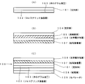
- FIG. 1 shows a cross-sectional view of the manufacturing process of the identification medium 100 of the embodiment.
- a support body 101 made of a material that transmits observation light and does not disturb the polarization state of transmitted light is prepared.
- a TAC (triacetyl cellulose) film is used as the support 101.
- a cholesteric liquid crystal layer 102 that selectively reflects light having a green center wavelength with right-handed circularly polarized light is formed on one surface thereof.
- a hologram type embss type
- a hologram type is pressed against the exposed surface of the cholesteric liquid crystal layer 102 to form irregularities that form a diffraction grating structure, thereby performing hologram processing 103. In this way, the state shown in FIG.
- an appropriate support for example, a PET film
- an easy peeling layer 105 is formed on one surface thereof.
- the easy peeling layer 105 is configured using an adhesive or an adhesive that can be easily peeled off.
- the optically anisotropic layer 106 is formed on the exposed surface.
- the optically anisotropic layer 106 is made of an oriented polymer material having birefringence, and is made of a material that undergoes a polymerization reaction of the polymer when exposed to light and whose orientation state is determined.
- the polymer in the optically anisotropic layer has an unreacted reactive group. Unreacted reactive groups react upon exposure to cause cross-linking of the polymer chains, and the degree of cross-linking of the polymer chains varies depending on exposure under different exposure conditions. As a result, the retardation value changes, resulting in a birefringence pattern. It is formed.
- the optically anisotropic layer 106 may have a retardation of 5 nm or more at 20 ° C., preferably 10 nm or more and 10,000 nm or less, and most preferably 20 nm or more and 2000 nm or less.
- a solution containing a liquid crystal compound having at least one reactive group is applied and dried to form a liquid crystal phase, and then irradiated with ionizing radiation to be polymerized and fixed. Adopt the method to do.
- This method is described in JP2009-175208A.
- a method of stretching a layer in which a monomer having at least two or more reactive groups is polymerized and immobilized, a reactive group is formed using a coupling agent in a layer made of a polymer.
- the optically anisotropic layer of the present invention may be formed by transfer.
- the thickness of the optically anisotropic layer 106 is preferably 0.1 to 20 ⁇ m, and more preferably 0.5 to 10 ⁇ m.
- a composition containing a liquid crystal compound (for example, a coating solution) is applied onto the easy-release layer 105 that has been subjected to an alignment treatment.
- a liquid crystal compound containing a rod-like liquid crystal, a horizontal alignment agent, a cationic photopolymerization initiator, a polymerization controller, and methyl ethyl ketone is used.
- this orientation state is fixed by irradiation of ionizing radiation.
- the alignment state of the aligned liquid crystal compound is fixed by a photopolymerization reaction.
- the irradiation energy for light irradiation is selected from 25 to 800 mJ / cm 2 .
- As the irradiation wavelength ultraviolet light having a peak at 250 to 450 nm is used.
- This adjustment is performed by changing the amount of light to be irradiated (exposure amount). Thereafter, by applying heat treatment at a temperature of 200 ° C., the state of fixation of the alignment state according to the light irradiation amount of light is determined, whereby the optically anisotropic layer 106 partially different in birefringence state is obtained. . If light is not applied, the orientation state is disturbed during heat treatment, and the birefringence of the region disappears (a simple light transmission layer).
- the above heat treatment can be performed at a temperature selected from the range of 50 ° C to 400 ° C.
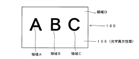
- the optically anisotropic layer 106 having a difference in the refractive index in the orthogonal direction in the plane and different states in the regions A, B, and C shown in FIG. 2 is obtained.
- the phase difference generated in these regions is set so that the regions A, B, and C appear to have different colors during observation using the circular polarizing filter.
- the region D is formed as a simple light transmission region having no refractive index anisotropy.
- a transfer adhesive layer 107 is formed on the exposed surface.
- the transfer adhesive layer 107 is formed using a light-transmitting adhesive material. In this way, the state shown in FIG.
- the transfer adhesive layer 107 of the laminate shown in FIG. 1B is bonded to the exposed surface of the support 101 of the laminate shown in FIG. 101 and the transfer adhesive layer 107 are bonded.
- an adhesive layer 108 to which a black or dark dye or pigment is added is provided on the exposed surface of the cholesteric liquid crystal layer 102, and a separator 109 that functions as a release paper is bonded to the adhesive layer 108.
- the easy-peeling layer 105 is peeled off from the optically anisotropic layer 106 to obtain the identification medium 100 shown in FIG.
- the optically anisotropic layer 106 and the cholesteric liquid crystal layer 102 overlap each other when viewed from the viewing side (upward direction in the figure).
- the separator 109 is peeled off, and the identification medium 100 is fixed to the article by the adhesive function of the adhesive layer 108.
- the adhesive layer 108 also functions as a light absorption layer that absorbs light incident from the optical anisotropic layer 106 side and transmitted through the cholesteric liquid crystal layer 102.
- the adhesive layer 108 functions as a light absorption layer.
- the adhesive layer 108 is light-transmitting, the surface of the article can be seen through the identification medium 100.
- the above description is an illustration and implementation of this invention is not limited to this content.
- the right-turn circularly polarized light having the green center wavelength gradually changes to elliptically polarized light because the phase components orthogonal to each other are lost in the process of passing through the regions A, B, and C of the optical anisotropic layer 106.
- This change to elliptical polarization is different in each of the regions A, B, and C.
- the state of the right-handed circularly polarized light is not changed, and the reflected light from the cholesteric liquid crystal layer 102 passes as it is.
- the reflected light from the areas A, B, and C passes through the right circular polarization filter, so that the right-handed circularly polarized light component therein is extracted.
- the light component has a color having a wavelength shifted from green, and the shift degree differs in each region. This is because the phase difference generated in the optical anisotropic layer 106 differs depending on the wavelength, and the generated phase difference has wavelength dependency. This is because the wavelength of the color corresponding to the phase difference is the center.
- the regions A, B, and C are set so that different phase differences are given. Therefore, when viewed through the right circular polarization filter, the images of the regions A, B, and C are as follows. Looks different colors. At this time, the colors of the regions A, B, and C appear not as green but as other colors close to the green wavelength. Since the original light is a spectrum of light having a green center wavelength, the amount of light of a color greatly separated from green (for example, blue or purple) is small. In addition, since no phase difference is given in the region D, the region D looks green, and at the same time, a hologram image resulting from the hologram processing 103 is observed.
- the identification medium 100 is observed through a left circular polarization filter that selectively transmits left-turn circularly polarized light
- a case where observation is performed with the left circular polarization filter in contact with the identification medium 100 will be described.
- the left circularly polarized light since the left circularly polarized light enters the region D from the observation surface side, there is no reflection from the cholesteric liquid crystal layer 102 overlapping the region D, and the region D looks black.
- the left circularly polarized light is incident, but a phase difference is generated due to the birefringence effect, so that the colors appear to correspond to the phase difference.
- the light from the regions A, B, and C is depolarized from the right-handed circularly polarized light
- the reflected light from the regions A, B, and C is respectively viewed through the right circular polarization filter.
- the color looks different from the case. Of course, depending on the setting state, it may appear dark and dark.
- the reflected light from the cholesteric liquid crystal layer 102 that passes through the regions A, B, and C is affected by the birefringence effect in the regions A, B, and C. For this reason, the areas A, B, and C can be seen in colors according to the phase difference generated in each area.
- the character images in the regions A, B, and C cannot be visually recognized directly, but when viewed through the left and right circular polarization filters, a latent image effect that can be seen in different colors can be obtained.
- a latent image effect can be obtained in which each image can be viewed in different colors when viewed through the left and right circularly polarizing filters. At this time, since different colors can be observed for each image, high discrimination can be obtained.
- the optical function does not change even if the circular polarizing filter used for observation is separated from the identification medium.
- the same identification function can be obtained even when the polarizing filter for observation is brought close to or in contact with the identification medium. For this reason, depending on how the polarizing filter for observation is used, an identification medium that does not have a disadvantage that the identification function is reduced or disappears is provided.
- the optical anisotropic layer is laminated on the metal reflection layer, when the polarizing filter is separated from the identification medium, the natural light component of the light incident on the identification medium increases, and the reflected light from the reflection layer is reduced. Close to natural light. Even when natural light passes through the optically anisotropic layer, a partial retardation difference (partial birefringence effect difference) does not appear, and the pattern of the optically anisotropic layer is not observed. That is, even if natural light including any polarization state is incident on the optical anisotropic layer at random, the emitted light is also natural light including any polarization state at random, so that the influence of a partial phase difference cannot be observed.
- the polarizing filter when the polarizing filter is separated from the identification medium, the optical function disappears and the identification effect is not exhibited. This becomes a factor that restricts the identification method in the identification using the identification medium. Alternatively, depending on how the filter is used, it becomes a factor that the identification function cannot be obtained. In the identification medium 100 of the present embodiment, an advantage that does not occur is obtained.
- the color of the latent image is given by the birefringence that the reflected light from the cholesteric liquid crystal layer receives when passing through the optically anisotropic layer. Without it, it is difficult to reproduce the color. For this reason, the identification medium which is hard to forge is obtained.
- the case of performing identification using a circular polarizing filter has been described as an example. However, it is possible to perform identification using color change even in observation through a linear polarizing filter. is there.
- FIG. 3 is a cross-sectional view illustrating an example of the identification medium according to the embodiment.
- FIG. 3 shows an identification medium 200. Parts of the identification medium 200 that are the same as those in FIG. 1 are the same as those described in relation to FIG. In the following, a description will be given mainly of portions of the identification medium 200 shown in FIG. 3 that are different from the identification medium 100 of FIG.
- the 3 has a structure in which a metal reflection layer 201 and a linear polarization layer 202 are laminated as a specific polarization reflection layer.
- the metal reflection layer 201 is a layer of a metal thin film having a metallic luster such as aluminum and functions as a light reflection layer.
- the linearly polarizing layer 202 is a layer that functions as a linearly polarizing filter that selectively transmits linearly polarized light in a certain direction.
- a configuration in which a diffraction grating or hologram processing is applied to the metal reflection layer 201 or the linear polarization layer 202 may be employed.
- the optical axis of the optically anisotropic layer 106 and the optical axis of the linearly polarizing layer 202 are deviated, and the optically anisotropic layer 106 is set so that a phase difference is generated in the linearly polarized light emitted from the linearly polarizing layer 202. ing.
- incident light is reflected by the metal reflection layer 201, and light used for identification does not reach the adhesive layer 108. Therefore, it is not necessary to darken the adhesive layer.
- the identification medium 200 is observed from the optically anisotropic layer 106 side.
- a linearly polarized light component in a specific direction contained therein passes through the linearly polarized light layer 202. Then, this light is reflected in the upper direction of the drawing by the metal reflection layer 202, and a phase difference is given by the optical anisotropic layer 106.
- the optical anisotropy layer 106 has optical anisotropy adjusted to the pattern described with reference to FIG. Therefore, the state of elliptically polarized light of the light emitted from the regions A, B, and C is different for each region. Further, the light emitted from the region D remains linearly polarized light emitted from the linearly polarizing layer 202.
- the change in polarization state (phase difference) given by the optically anisotropic layer 106 is not recognized, and the image in FIG. 2 is not recognized.
- the linear polarizing plate for observation is rotated relative to the identification medium 200, the plane of polarization of the linearly polarized light that is transmitted changes, so that the density and color of each image being observed changes.
- the specific polarization reflection layer has a structure in which a metal reflection layer and a circular polarization filter layer that selectively transmits circularly polarized light in a specific turning direction when natural light is incident on the observation surface side.
- FIG. 4 shows an identification medium 300 according to the embodiment.
- the identification medium 300 includes a separator 301, an adhesive layer 302 (adhesive layer), a metal reflective layer 303, a hologram forming layer 305, a transfer adhesive layer 306, a linearly polarizing layer 307, a retardation layer 308, from the side attached to the object.
- the transfer adhesive layer 310 and the optically anisotropic layer 311 are stacked.
- the separator 301 is affixed to the exposed surface of the adhesive layer 302, and is peeled off from the adhesive layer 302 when the identification medium 300 is affixed to an object.
- the adhesive layer 302 has a function of attaching and fixing the identification medium 300 to an object.
- the metal reflection layer 303 is a metal deposition layer such as aluminum.
- the hologram forming layer 305 is a transparent resin layer, and is embossed to form a hologram on the metal reflective layer 303 side. A hologram image can be observed by vapor-depositing the metal reflective layer 303 on the embossed structure.
- the transfer adhesive layer 306 is a transparent adhesive layer that adheres the hologram forming layer 305 and the linearly polarizing layer 307.
- the linearly polarizing layer 307 and the retardation layer 308 constitute a circularly polarizing layer 309.
- the circularly polarizing layer 309 functions as a circularly polarizing filter that selectively transmits the right circularly polarized light toward the observation surface (upward direction in the figure) when natural light is incident from the lower direction in the figure. That is, the linearly polarizing layer 307 is a layer of a linearly polarizing filter that selectively transmits linearly polarized light in a specific direction, the retardation layer 308 is a ⁇ / 4 plate, and the phase difference between the absorption axis of the linearly polarizing layer 307.
- the right circularly polarized light is selectively transmitted upward in the figure when natural light is incident from the downward direction in the figure.
- the turning direction of the circularly polarized light that is selectively transmitted upward in the figure of the circularly polarizing layer 309 may be a leftward turning.
- the selection of the turning direction is set by selecting a direction in which the absorption axis of the linearly polarizing layer 307 and the slow axis of the retardation layer 308 are shifted by 45 °.
- the transfer adhesive layer 310 is a transparent adhesive layer that adheres the circularly polarizing layer 309 and the optical anisotropy 311.
- the optically anisotropic layer 311 is the same as the optically anisotropic layer 106 in FIG. Similar to the optically anisotropic layer 106 in FIG. 1, the optically anisotropic layer 311 in FIG. 4 is formed with the optically anisotropic pattern shown in FIG. That is, the optically anisotropic layer 311 has a difference in refractive index in the orthogonal direction in the plane, and the state of the difference is different in the regions A, B, and C shown in FIG. . Further, the region D is a simple light transmission region having no refractive index anisotropy.
- a film in which the linearly polarizing layer 307 and the retardation layer 308 are bonded together is manufactured.
- the hologram forming layer 305 is embossed in advance, and an aluminum vapor deposition film is formed on the surface of the hologram forming layer 305, so that the metal reflective layer 303 on which the hologram processing 304 is applied is manufactured.
- the hologram forming layer 305 provided with the metal reflective layer 303 is provided via the transfer adhesive layer 306. paste.
- the optically anisotropic layer 311 is fixed to the retardation layer 308 via the transfer adhesive layer 310.
- the optically anisotropic layer 311 is prepared by the same manufacturing method as that of the optically anisotropic layer 106 described in the first embodiment and is peeled off from the base material.
- an adhesive layer 302 is formed, and a separator 301 is affixed to the exposed surface to obtain an identification medium 300 shown in FIG.
- the identification medium 300 is observed from the upper direction in FIG. First, when the identification medium 300 is directly viewed, a hologram image (not shown) resulting from the hologram processing 304 is observed. At this time, since the naked eye cannot distinguish the difference in birefringence, the characters in the regions A, B, and C shown in FIG. 2 cannot be visually recognized.
- each region A, B, and C has a different color due to the birefringence effect corresponding to the difference in birefringence (difference in retardation value).
- the region D since the right-circularly polarized reflected light is observed through the right-circularly polarized light filter, metallic glossy reflected light can be seen, and at the same time, a hologram image (not shown) resulting from the hologram processing 304. Are visible at the same time.
- the same observation is performed in a state where the right circular polarization filter is separated from the identification medium 300, natural light is incident on the circular polarization layer 309 from the upper side of the figure.
- the incident light on the layer 303 is linearly polarized light similar to that obtained when the right circular polarization filter is brought into contact with the identification medium 300, and the optical function is the same as that described above. That is, in the observation through the right circular polarization filter, the observed content is the same whether the right circular polarization filter is brought into contact with the identification medium 300 or separated from the identification medium 300.
- This reflected light is transmitted through the circularly polarizing layer 309 in the upward direction of the figure, further passes through the optically anisotropic layer 311 in the upward direction of the figure, and is observed through the left circularly polarizing filter.
- the light from the regions A, B, and C observed through the left circular polarizing filter is subjected to different birefringence effects in each region, and the peak wavelengths transmitted through the left circular polarizing filter are different. appear. In this way, the hologram image is almost invisible, and the regions A, B, and C appear in different colors on a black background.
- the identification medium 300 is observed through the left circular polarization filter in a state where the left circular polarization filter is separated from the identification medium 300
- natural light is incident on the circularly polarizing layer 309 from the upper surface of the drawing, but is reflected by the metal reflecting layer 303 by the function of the circularly polarizing layer 309 and is incident on the optically anisotropic layer 311 from the lower side of the drawing.
- the light is mainly right-handed circularly polarized light, and light incident on a part of the regions A, B, and C is elliptically polarized light. For this reason, the reflected light from the region D is right circularly polarized light and is blocked by the left circular polarization filter for observation.
- the region D appears black.
- the regions A, B, and C are subjected to a birefringence effect in the optical anisotropic layer 311 and include components that pass through the left circularly polarizing filter. appear.
- the identification function may not be stably obtained depending on the observation method, and the authenticity may not be accurately determined. Increase. This is not preferable because it increases the possibility that accurate authentication cannot be performed when a person with little experience, such as a general user, performs authentication.
- the preset optical identification function can be reliably observed, so this problem is reduced.
- FIG. 4 shows an example in which the optically anisotropic layer 311 is exposed, but a structure in which the surface is covered with a transparent protective layer is also possible.
- the hologram processing 304 may be processing for forming a diffraction grating.
- the linearly polarizing layer 307 a material obtained by mixing iodine and dichroic dye into PVA (polyvinyl alcohol) and stretching, a material obtained by applying and orienting lyotropic liquid crystal, a wire grid polarizing layer, and the like can be used.
- the retardation layer 308 a stretched PC (polycarbonate) or (COP) cycloolefin polymer or a liquid crystal having anisotropy can be used.
- the optically anisotropic layer may be composed of a light-transmitting film pattern having birefringence.
- the position of the hologram processing 103 may be on the other side of the cholesteric liquid crystal layer 102 or on both sides. Note that the pattern shown in FIG. 2 is an example, and may be a design or a pattern.
- the device for expanding the wavelength range of the reflected light from the cholesteric liquid crystal layer will be described.
- the area of the cholesteric liquid crystal layer is finely divided, and a cholesteric liquid crystal layer is constituted by a plurality of dot-like cholesteric liquid crystal areas.
- This cholesteric liquid crystal layer is formed by forming a dot-like cholesteric liquid crystal region by ejecting a stock solution of a cholesteric liquid crystal layer from a nozzle in the same manner as ink jet, using the principle of an ink jet printing apparatus.
- Cholesteric liquid crystal has the property that the central wavelength of reflected light is determined by the pitch width of the spiral structure. Therefore, by arranging the dot-like regions of the cholesteric liquid crystal that selectively reflects light of two different central wavelengths in a checkered pattern, the wavelength band of light reflected from the entire cholesteric liquid crystal layer is widened. For this reason, an image of a wider range of wavelengths can be used for identification. For example, in observation through an optical filter, it is possible to obtain identification characteristics such that the image of the region A looks red and the image of the region C looks blue.
- cholesteric liquid crystal regions having two types of pitches are used to obtain reflected light of two types of center wavelengths.
- the number of different pitches is further increased so that light of more center wavelengths can be obtained. It is good also as a structure reflected.
- a configuration in which a plurality of cholesteric liquid crystal regions having a plurality of different pitches is arranged in a stripe shape instead of a checkerboard pattern is also possible.
- a reflective layer in which cholesteric liquid crystal phases reflecting two central wavelengths are mixed by preparing liquid crystal ink in which cholesteric liquid crystals having different pitches are dispersed in ink.
- a configuration in which a cholesteric liquid crystal layer having three central wavelengths of RGB is stacked to widen the wavelength range of reflected light is also possible.
- the present invention can be used for a technique for identifying authenticity.
Abstract
Description
(識別媒体1)
以下、特定偏光反射層としてコレステリック液晶層を用いた識別媒体の一例を説明する。図1には、実施形態の識別媒体100の製造工程の断面図が示されている。まず、製造工程の概略を説明する。まず、図1(A)に示すように、観察光を透過し、透過光の偏光状態を乱さない材質で構成された支持体101を用意する。この例では、支持体101としてTAC(トリアセチルセルロール)フィルムを利用する。支持体101を用意したら、その一面に右旋回円偏光で緑の中心波長の光を選択的に反射するコレステリック液晶層102を形成する。そして、コレステリック液晶層102の露出した表面にホログラム型(エンボス型)を押し付け、回折格子構造となる凹凸を形成することで、ホログラム加工103を施す。こうして図1(A)に示す状態を得る。
まず、識別媒体100を直視した場合を説明する。この場合、識別媒体100に光学異方性層106の側から入射した光の内、緑の中心波長を有する右旋回円偏光がコレステリック液晶層102から図の上の方向に反射される。この緑の中心波長を有する右旋回円偏光の反射光は、光学異方性層106を図の下から上の方向に通過する。
本実施形態によれば、直視では視認できず、左右の円偏光フィルタを介して見ると、各像が異なる色彩で見える潜像効果が得られる。この際、像毎に異なる色彩を観察できるので、高い識別性が得られる。
(識別媒体2)
以下、特定偏光反射層として金属反射層と直線偏光フィルタ層の積層構造を用いた識別媒体の一例を説明する。図3は、実施形態の識別媒体の一例を示す断面図である。図3には、識別媒体200が示されている。識別媒体200における図1と同じ符号の部分は、図1に関連して説明した部分と同じである。以下、主に図3に示す識別媒体200における図1の識別媒体100と異なる部分について説明する。
(識別媒体3)
以下、特定偏光反射層が、金属反射層と、観察面側に向かって自然光を入射させた際に特定の旋回方向の円偏光を選択的に透過する円偏光フィルタ層とを積層した構造を有する識別媒体の一例を説明する。図4には、実施形態の識別媒体300が示されている。識別媒体300は、対象物に貼り付けられる側から、セパレータ301、粘着層302(粘着層)、金属反射層303、ホログラム形成層305、転写接着層306、直線偏光層307、位相差層308、転写接着層310、光学異方性層311と積層された構造を有する。
まず、直線偏光層307と位相差層308とを貼り合わせたフィルムを作製する。また、予めホログラム形成層305にエンボス加工を施し、その面にアルミ蒸着膜を形成し、ホログラム加工304が施された金属反射層303を作製する。次に、上記の直線偏光層307と位相差層308とを貼り合わせたフィルムの直線偏光層307の側に、転写接着層306を介して、金属反射層303が設けられたホログラム形成層305を貼り付ける。そして、位相差層308に転写接着層310を介して光学異方性層311を固定する。光学異方性層311は、第1の実施形態で説明した光学異方性層106と同様な製造方法で作成し、基材から剥がしたものを使用する。最後に粘着層302を形成し、その露出面にセパレータ301を貼り付けることで図4に示す識別媒体300を得る。
識別媒体300の観察は、図4の上の方向から行なわれる。まず、識別媒体300を直接見ると、ホログラム加工304に起因するホログラム像(図示省略)が観察される。この際、肉眼は複屈折性の違いを区別できないので、図2に示す領域A、B、Cの文字は視認できない。
上述した左右の円偏光フィルタを介した観察における見え方は、円偏光フィルタを識別媒体300に接触させた場合であっても、識別媒体300から離した状態であっても同じである。これは、円偏光層309の機能により、光学異方性層311に図の下方から入射する光が右円偏光に制限されるからである。また、円偏光を観察の対象としているので、円偏光フィルタを回転(あるいは逆に識別媒体300を回転)させても観察される内容に変化は生じない。このような特性は、観察の仕方が多少ラフであっても安定した識別機能を得る上で都合がよい。例えば、ビューアである円偏光フィルタと識別媒体との位置関係や角度位置の関係がシビアであると、観察の仕方によって識別機能が安定して得られず、真贋判定を正確に行えない可能性が増大する。これは、一般ユーザ等の経験の少ない者が真贋の判定を行う場合に、正確な真贋判定が行えない可能性が増大するので、好ましくない。これに対して、本実施形態の場合、上述したように多少ラフな方法であっても、予め設定された光学識別機能が確実に観察できるので、この問題が軽減される。
図4には、光学異方性層311が露出した例が示されているが、その表面を透明な保護層で覆う構造も可能である。ホログラム加工304は、回折格子を形成する加工であってもよい。直線偏光層307としては、PVA(ポリビニルアルコール)にヨウ素や二色性色素を混入し延伸したもの、リオトロピック液晶を塗布し配向させたもの、ワイヤーグリッドの偏光層等を利用できる。位相差層308は、PC(ポリカーボネート)や(COP)シクロオレフィンポリマーを延伸したものや異方性をもつ液晶を配向したものを利用できる。
光学異方性層は、複屈折性を有する光透透過性のフィルムパターンにより構成してもよい。この場合、図2に示すパターンを有する複屈折性を有する光透透過性のフィルムパターンを用意し、それを易剥離層105に転写する工程を採用すればよい。ホログラム加工103の位置は、コレステリック液晶層102の他の面の側でもよく、また両面であってもよい。なお、図2に示すパターンは、一例であり、図柄や模様であってもよい。
Claims (6)
- 特定の偏光状態にある光を反射する特定偏光反射層と、
前記特定偏光反射層と重なる位置に配置され、面内で光学異方性を有する光学異方性層と
を備え、
前記光学異方性層には、他の領域と異なる光学異方性を有する領域により構成される第1の像が設けられていることを特徴とする識別媒体。 - 前記特定偏光反射層がコレステリック液晶層であることを特徴とする請求項1に記載の識別媒体。
- 前記特定偏光反射層が金属反射層と特定方向の直線偏光を選択的に透過する光学フィルタ層とを積層した構造を有することを特徴とする請求項1に記載の識別媒体。
- 前記特定偏光反射層が、
金属反射層と、
観察面側に向かって自然光を入射させた際に特定の旋回方向の円偏光を選択的に透過する円偏光フィルタ層と
を積層した構造を有することを特徴とする請求項1に記載の識別媒体。 - 前記特定偏光反射層にホログラム加工が施されていることを特徴とする請求項1~4のいずれか一項に記載の識別媒体。
- 請求項1~5のいずれか一項に記載の識別媒体を、当該識別媒体から離れた位置に配置した特定の方向の偏光を選択的に透過する偏光フィルタを介して観察することを特徴とする識別方法。
Priority Applications (5)
| Application Number | Priority Date | Filing Date | Title |
|---|---|---|---|
| EP10833089.5A EP2506065B1 (en) | 2009-11-27 | 2010-11-12 | Identification medium and identification method therefor |
| CN2010800535069A CN102667580A (zh) | 2009-11-27 | 2010-11-12 | 识别介质及其识别方法 |
| KR1020127015742A KR101392614B1 (ko) | 2009-11-27 | 2010-11-12 | 식별 매체 및 그 식별 방법 |
| JP2011543210A JP5462884B2 (ja) | 2009-11-27 | 2010-11-12 | 識別媒体およびその識別方法 |
| US13/509,916 US8970953B2 (en) | 2009-11-27 | 2010-11-12 | Identification medium and identification method therefor |
Applications Claiming Priority (2)
| Application Number | Priority Date | Filing Date | Title |
|---|---|---|---|
| JP2009-270012 | 2009-11-27 | ||
| JP2009270012 | 2009-11-27 |
Publications (2)
| Publication Number | Publication Date |
|---|---|
| WO2011065242A1 true WO2011065242A1 (ja) | 2011-06-03 |
| WO2011065242A8 WO2011065242A8 (ja) | 2012-05-10 |
Family
ID=44066347
Family Applications (1)
| Application Number | Title | Priority Date | Filing Date |
|---|---|---|---|
| PCT/JP2010/070212 WO2011065242A1 (ja) | 2009-11-27 | 2010-11-12 | 識別媒体およびその識別方法 |
Country Status (6)
| Country | Link |
|---|---|
| US (1) | US8970953B2 (ja) |
| EP (1) | EP2506065B1 (ja) |
| JP (1) | JP5462884B2 (ja) |
| KR (1) | KR101392614B1 (ja) |
| CN (1) | CN102667580A (ja) |
| WO (1) | WO2011065242A1 (ja) |
Cited By (9)
| Publication number | Priority date | Publication date | Assignee | Title |
|---|---|---|---|---|
| JP2013233733A (ja) * | 2012-05-09 | 2013-11-21 | Toppan Printing Co Ltd | 偽造防止媒体、偽造防止ステッカー、偽造防止転写箔及び検証方法 |
| JP2014162200A (ja) * | 2013-02-27 | 2014-09-08 | Toppan Printing Co Ltd | 偽造防止媒体及びその真贋判定方法 |
| JP2015069070A (ja) * | 2013-09-30 | 2015-04-13 | 凸版印刷株式会社 | 偽造防止用デバイスおよびその真偽判定方法 |
| JP2017529568A (ja) * | 2014-09-05 | 2017-10-05 | コーロン インダストリーズ インク | セキュリティーフィルム |
| JP2018517175A (ja) * | 2015-05-26 | 2018-06-28 | ロリク アーゲーRolic Ag | 光学セキュリティ装置 |
| JPWO2017110225A1 (ja) * | 2015-12-25 | 2018-10-18 | Jxtgエネルギー株式会社 | 光学フィルム |
| WO2021153761A1 (ja) * | 2020-01-31 | 2021-08-05 | 日本ゼオン株式会社 | 識別媒体、物品、及び識別媒体の使用方法 |
| US11150392B2 (en) | 2016-11-24 | 2021-10-19 | Osaka University | Optical element and production method for optical element |
| WO2022209852A1 (ja) * | 2021-03-30 | 2022-10-06 | 日本ゼオン株式会社 | 光学表示媒体、物品、及び光学表示媒体の使用方法 |
Families Citing this family (9)
| Publication number | Priority date | Publication date | Assignee | Title |
|---|---|---|---|---|
| WO2011092922A1 (ja) * | 2010-01-28 | 2011-08-04 | 日本発條株式会社 | 識別媒体およびその識別方法 |
| CN106461847A (zh) * | 2014-06-30 | 2017-02-22 | 日本瑞翁株式会社 | 识别介质、识别介质的制造方法和识别介质的使用方法 |
| CN104385801B (zh) * | 2014-11-18 | 2017-01-25 | 浙江京华激光科技股份有限公司 | 一种用于纸质证件的微纳米全息防伪膜及生产工艺和应用 |
| AU2016267565B2 (en) * | 2015-05-26 | 2021-08-12 | Rolic Ag | Multiple hidden image security device |
| EP3364378A4 (en) * | 2015-10-08 | 2019-07-03 | Universidad Politécnica de Madrid | OPTICAL ELEMENT AND MANUFACTURING METHOD WITH MULTIPLE LATENT IMAGES FOR SECURITY OF DOCUMENTS |
| WO2018212348A1 (ja) * | 2017-05-19 | 2018-11-22 | 富士フイルム株式会社 | 光学素子および光学装置 |
| CN110250667B (zh) * | 2019-06-28 | 2023-12-29 | 深圳市华圣达拉链有限公司 | 滤色拉链结构 |
| KR20210138980A (ko) * | 2020-05-13 | 2021-11-22 | 엔비에스티(주) | 편광물질을 포함하는 위변조 방지수단 및 이의 활용방법 |
| CN113147216B (zh) * | 2021-05-24 | 2022-09-13 | 中钞印制技术研究院有限公司 | 光学防伪元件及其检测、制造方法和装置、安全物品 |
Citations (5)
| Publication number | Priority date | Publication date | Assignee | Title |
|---|---|---|---|---|
| JP3652487B2 (ja) | 1997-11-20 | 2005-05-25 | 日本発条株式会社 | 対象物の識別用媒体及び識別構造及び識別方法 |
| JP2007001130A (ja) | 2005-06-23 | 2007-01-11 | Nitto Denko Corp | 積層反射体、認証カード、バーコードラベル、認証システム、及び、認証領域形成システム |
| JP2009069793A (ja) * | 2006-11-21 | 2009-04-02 | Fujifilm Corp | 複屈折パターンを有する物品の製造方法 |
| JP2009175208A (ja) | 2008-01-22 | 2009-08-06 | Fujifilm Corp | 複屈折パターンを有する物品の製造方法 |
| JP2009222775A (ja) * | 2008-03-13 | 2009-10-01 | Toppan Printing Co Ltd | セキュリティデバイス及びラベル付き物品 |
Family Cites Families (27)
| Publication number | Priority date | Publication date | Assignee | Title |
|---|---|---|---|---|
| US5284364A (en) * | 1992-06-10 | 1994-02-08 | Anvik Corporation | Increased-security identification card system |
| JPH0968927A (ja) * | 1995-09-01 | 1997-03-11 | Nitto Denko Corp | 偽造防止方法及びそのラベル |
| CN1163765C (zh) * | 1997-05-09 | 2004-08-25 | 罗利克有限公司 | 光学元件和包含它的防伪或防拷贝元器件 |
| EP0911758B1 (en) | 1997-07-29 | 2005-11-30 | Nhk Spring Co.Ltd. | Optical identification system using cholesteric liquid crystals |
| US6496287B1 (en) * | 1998-04-09 | 2002-12-17 | Rolic Ag | Optical identification element |
| WO2000013065A1 (en) * | 1998-08-27 | 2000-03-09 | Nippon Mitsubishi Oil Corporation | Genuineness detecting system and method for using genuineness detecting film |
| JP4335352B2 (ja) * | 1999-03-05 | 2009-09-30 | 大日本印刷株式会社 | 偽造防止体及び偽造判別方法 |
| US6344887B1 (en) * | 1999-09-10 | 2002-02-05 | Yao-Dong Ma | Full spectrum reflective choleterics display employing circular polarizers with the same polarity but different disposition |
| EP1120737A1 (en) * | 2000-01-27 | 2001-08-01 | Rolic AG | Optical security device |
| GB0201767D0 (en) * | 2002-01-25 | 2002-03-13 | Rue De Int Ltd | Improvements in methods of manufacturing substrates |
| JP2003231380A (ja) * | 2002-02-12 | 2003-08-19 | Nhk Spring Co Ltd | 対象物の識別媒体及び識別方法 |
| TWI258603B (en) * | 2002-04-23 | 2006-07-21 | Nitto Denko Corp | Polarized light device, polarized light source and image display apparatus using the same |
| JP4392826B2 (ja) * | 2003-05-16 | 2010-01-06 | 日本発條株式会社 | 対象物の識別媒体及び識別方法 |
| JP4257903B2 (ja) * | 2003-10-28 | 2009-04-30 | 日本発條株式会社 | 識別媒体、識別媒体の識別方法、識別対象物品および識別装置 |
| US20070081144A1 (en) * | 2003-12-26 | 2007-04-12 | Nhk Spring Co., Ltd. | Discrimination medium and discrimination method for discriminating the same |
| DE102004018702B4 (de) * | 2004-04-17 | 2006-05-24 | Leonhard Kurz Gmbh & Co. Kg | Folie mit Polymerschicht |
| JP4670470B2 (ja) * | 2005-05-16 | 2011-04-13 | 凸版印刷株式会社 | 隠蔽画像積層体およびその製造方法 |
| JP4967415B2 (ja) * | 2006-03-31 | 2012-07-04 | 大日本印刷株式会社 | 真正性判定システム |
| JP4866129B2 (ja) | 2006-04-03 | 2012-02-01 | 日本発條株式会社 | 識別媒体、識別方法および識別装置 |
| JP4959304B2 (ja) * | 2006-11-22 | 2012-06-20 | 日本発條株式会社 | 識別媒体、識別方法および識別装置 |
| JP4935328B2 (ja) | 2006-11-30 | 2012-05-23 | 凸版印刷株式会社 | 積層体、粘着ラベル、記録媒体、ラベル付き物品、検証具、キット及び判別方法 |
| JP5028642B2 (ja) * | 2006-11-30 | 2012-09-19 | 凸版印刷株式会社 | 積層体、粘着ラベル、記録媒体、ラベル付き物品及び判別方法 |
| JP5211474B2 (ja) | 2006-11-30 | 2013-06-12 | 凸版印刷株式会社 | 積層体、粘着ラベル、記録媒体及びラベル付き物品 |
| JP5380007B2 (ja) * | 2008-06-16 | 2014-01-08 | 富士フイルム株式会社 | 偽造防止媒体 |
| JP5361536B2 (ja) * | 2009-05-26 | 2013-12-04 | 富士フイルム株式会社 | 複屈折パターン認証用ビューワ、複屈折パターン認証用キット、真正性認証媒体、および真正性認証方法 |
| WO2011092922A1 (ja) * | 2010-01-28 | 2011-08-04 | 日本発條株式会社 | 識別媒体およびその識別方法 |
| JP5412350B2 (ja) * | 2010-03-26 | 2014-02-12 | 富士フイルム株式会社 | 複屈折パターンを有する物品 |
-
2010
- 2010-11-12 JP JP2011543210A patent/JP5462884B2/ja not_active Expired - Fee Related
- 2010-11-12 EP EP10833089.5A patent/EP2506065B1/en not_active Not-in-force
- 2010-11-12 KR KR1020127015742A patent/KR101392614B1/ko active IP Right Grant
- 2010-11-12 US US13/509,916 patent/US8970953B2/en not_active Expired - Fee Related
- 2010-11-12 WO PCT/JP2010/070212 patent/WO2011065242A1/ja active Application Filing
- 2010-11-12 CN CN2010800535069A patent/CN102667580A/zh active Pending
Patent Citations (5)
| Publication number | Priority date | Publication date | Assignee | Title |
|---|---|---|---|---|
| JP3652487B2 (ja) | 1997-11-20 | 2005-05-25 | 日本発条株式会社 | 対象物の識別用媒体及び識別構造及び識別方法 |
| JP2007001130A (ja) | 2005-06-23 | 2007-01-11 | Nitto Denko Corp | 積層反射体、認証カード、バーコードラベル、認証システム、及び、認証領域形成システム |
| JP2009069793A (ja) * | 2006-11-21 | 2009-04-02 | Fujifilm Corp | 複屈折パターンを有する物品の製造方法 |
| JP2009175208A (ja) | 2008-01-22 | 2009-08-06 | Fujifilm Corp | 複屈折パターンを有する物品の製造方法 |
| JP2009222775A (ja) * | 2008-03-13 | 2009-10-01 | Toppan Printing Co Ltd | セキュリティデバイス及びラベル付き物品 |
Non-Patent Citations (1)
| Title |
|---|
| See also references of EP2506065A4 * |
Cited By (10)
| Publication number | Priority date | Publication date | Assignee | Title |
|---|---|---|---|---|
| JP2013233733A (ja) * | 2012-05-09 | 2013-11-21 | Toppan Printing Co Ltd | 偽造防止媒体、偽造防止ステッカー、偽造防止転写箔及び検証方法 |
| JP2014162200A (ja) * | 2013-02-27 | 2014-09-08 | Toppan Printing Co Ltd | 偽造防止媒体及びその真贋判定方法 |
| JP2015069070A (ja) * | 2013-09-30 | 2015-04-13 | 凸版印刷株式会社 | 偽造防止用デバイスおよびその真偽判定方法 |
| JP2017529568A (ja) * | 2014-09-05 | 2017-10-05 | コーロン インダストリーズ インク | セキュリティーフィルム |
| JP2018517175A (ja) * | 2015-05-26 | 2018-06-28 | ロリク アーゲーRolic Ag | 光学セキュリティ装置 |
| JPWO2017110225A1 (ja) * | 2015-12-25 | 2018-10-18 | Jxtgエネルギー株式会社 | 光学フィルム |
| US11150392B2 (en) | 2016-11-24 | 2021-10-19 | Osaka University | Optical element and production method for optical element |
| WO2021153761A1 (ja) * | 2020-01-31 | 2021-08-05 | 日本ゼオン株式会社 | 識別媒体、物品、及び識別媒体の使用方法 |
| CN114981693A (zh) * | 2020-01-31 | 2022-08-30 | 日本瑞翁株式会社 | 识别介质、物品以及识别介质的使用方法 |
| WO2022209852A1 (ja) * | 2021-03-30 | 2022-10-06 | 日本ゼオン株式会社 | 光学表示媒体、物品、及び光学表示媒体の使用方法 |
Also Published As
| Publication number | Publication date |
|---|---|
| JP5462884B2 (ja) | 2014-04-02 |
| JPWO2011065242A1 (ja) | 2013-04-11 |
| CN102667580A (zh) | 2012-09-12 |
| EP2506065A4 (en) | 2013-07-03 |
| KR20120094052A (ko) | 2012-08-23 |
| US20120236292A1 (en) | 2012-09-20 |
| KR101392614B1 (ko) | 2014-05-07 |
| EP2506065A1 (en) | 2012-10-03 |
| WO2011065242A8 (ja) | 2012-05-10 |
| EP2506065B1 (en) | 2015-04-29 |
| US8970953B2 (en) | 2015-03-03 |
Similar Documents
| Publication | Publication Date | Title |
|---|---|---|
| JP5462884B2 (ja) | 識別媒体およびその識別方法 | |
| JP5245296B2 (ja) | 偽造防止媒体および判別方法 | |
| JP5597940B2 (ja) | 表示体、粘着ラベル、転写箔及びラベル付き物品 | |
| KR101510919B1 (ko) | 식별 매체 및 그 제조 방법 | |
| EP2006750B1 (en) | Discrimination medium, discrimination method, and discrimination device | |
| US9298036B2 (en) | Identification medium | |
| JP6268941B2 (ja) | 偽造防止用デバイスおよびその製造方法 | |
| US8168080B2 (en) | Identifying medium, identifying medium manufacturing method, article, and identifying medium identifying method | |
| JP5045328B2 (ja) | 光学素子、ラベル付き物品、光学キット及び判別方法 | |
| KR20070043797A (ko) | 이방성 광학 장치 및 이의 제조방법 | |
| JP5239509B2 (ja) | 光学素子、ラベル付き物品及び光学キット | |
| JP5638287B2 (ja) | 識別媒体およびその識別方法 | |
| JP4978403B2 (ja) | 光学素子、ラベル付き物品、光学キット及び判別方法 | |
| JP5125418B2 (ja) | 光学素子、ラベル付き物品、光学キット及び判別方法 | |
| JP2008256926A (ja) | セキュリティデバイス、ラベル付き印刷物および判別方法 | |
| WO2017204168A1 (ja) | 偽造防止媒体 | |
| JP4905023B2 (ja) | 偽造防止媒体、偽造防止ラベル、印刷物、転写箔、および判別方法 | |
| JP5842495B2 (ja) | 情報記録媒体 | |
| JP2011242714A (ja) | 偽造防止シート、偽造防止用ラベル、偽造防止用転写シート、偽造防止物品及び真偽判定方法 | |
| JP5380791B2 (ja) | 光学素子、ラベル付き物品、光学キット及び判別方法 | |
| JP5141108B2 (ja) | 光学素子、ラベル付き物品、光学キット及び判別方法 |
Legal Events
| Date | Code | Title | Description |
|---|---|---|---|
| WWE | Wipo information: entry into national phase |
Ref document number: 201080053506.9 Country of ref document: CN |
|
| 121 | Ep: the epo has been informed by wipo that ep was designated in this application |
Ref document number: 10833089 Country of ref document: EP Kind code of ref document: A1 |
|
| WWE | Wipo information: entry into national phase |
Ref document number: 2011543210 Country of ref document: JP |
|
| WWE | Wipo information: entry into national phase |
Ref document number: 13509916 Country of ref document: US |
|
| NENP | Non-entry into the national phase |
Ref country code: DE |
|
| ENP | Entry into the national phase |
Ref document number: 20127015742 Country of ref document: KR Kind code of ref document: A |
|
| WWE | Wipo information: entry into national phase |
Ref document number: 2010833089 Country of ref document: EP |