EP2506060B1 - Zoom lens and image pickup apparatus including the same - Google Patents
Zoom lens and image pickup apparatus including the same Download PDFInfo
- Publication number
- EP2506060B1 EP2506060B1 EP12002247.0A EP12002247A EP2506060B1 EP 2506060 B1 EP2506060 B1 EP 2506060B1 EP 12002247 A EP12002247 A EP 12002247A EP 2506060 B1 EP2506060 B1 EP 2506060B1
- Authority
- EP
- European Patent Office
- Prior art keywords
- lens unit
- sub
- lens
- refractive power
- focal length
- Prior art date
- Legal status (The legal status is an assumption and is not a legal conclusion. Google has not performed a legal analysis and makes no representation as to the accuracy of the status listed.)
- Active
Links
Images


Classifications
-
- G—PHYSICS
- G02—OPTICS
- G02B—OPTICAL ELEMENTS, SYSTEMS OR APPARATUS
- G02B15/00—Optical objectives with means for varying the magnification
- G02B15/14—Optical objectives with means for varying the magnification by axial movement of one or more lenses or groups of lenses relative to the image plane for continuously varying the equivalent focal length of the objective
- G02B15/144—Optical objectives with means for varying the magnification by axial movement of one or more lenses or groups of lenses relative to the image plane for continuously varying the equivalent focal length of the objective having four groups only
- G02B15/1441—Optical objectives with means for varying the magnification by axial movement of one or more lenses or groups of lenses relative to the image plane for continuously varying the equivalent focal length of the objective having four groups only the first group being positive
- G02B15/144113—Optical objectives with means for varying the magnification by axial movement of one or more lenses or groups of lenses relative to the image plane for continuously varying the equivalent focal length of the objective having four groups only the first group being positive arranged +-++
-
- G—PHYSICS
- G02—OPTICS
- G02B—OPTICAL ELEMENTS, SYSTEMS OR APPARATUS
- G02B15/00—Optical objectives with means for varying the magnification
- G02B15/14—Optical objectives with means for varying the magnification by axial movement of one or more lenses or groups of lenses relative to the image plane for continuously varying the equivalent focal length of the objective
- G02B15/16—Optical objectives with means for varying the magnification by axial movement of one or more lenses or groups of lenses relative to the image plane for continuously varying the equivalent focal length of the objective with interdependent non-linearly related movements between one lens or lens group, and another lens or lens group
- G02B15/163—Optical objectives with means for varying the magnification by axial movement of one or more lenses or groups of lenses relative to the image plane for continuously varying the equivalent focal length of the objective with interdependent non-linearly related movements between one lens or lens group, and another lens or lens group having a first movable lens or lens group and a second movable lens or lens group, both in front of a fixed lens or lens group
- G02B15/167—Optical objectives with means for varying the magnification by axial movement of one or more lenses or groups of lenses relative to the image plane for continuously varying the equivalent focal length of the objective with interdependent non-linearly related movements between one lens or lens group, and another lens or lens group having a first movable lens or lens group and a second movable lens or lens group, both in front of a fixed lens or lens group having an additional fixed front lens or group of lenses
- G02B15/173—Optical objectives with means for varying the magnification by axial movement of one or more lenses or groups of lenses relative to the image plane for continuously varying the equivalent focal length of the objective with interdependent non-linearly related movements between one lens or lens group, and another lens or lens group having a first movable lens or lens group and a second movable lens or lens group, both in front of a fixed lens or lens group having an additional fixed front lens or group of lenses arranged +-+
-
- G—PHYSICS
- G02—OPTICS
- G02B—OPTICAL ELEMENTS, SYSTEMS OR APPARATUS
- G02B13/00—Optical objectives specially designed for the purposes specified below
- G02B13/001—Miniaturised objectives for electronic devices, e.g. portable telephones, webcams, PDAs, small digital cameras
- G02B13/009—Miniaturised objectives for electronic devices, e.g. portable telephones, webcams, PDAs, small digital cameras having zoom function
-
- G—PHYSICS
- G02—OPTICS
- G02B—OPTICAL ELEMENTS, SYSTEMS OR APPARATUS
- G02B3/00—Simple or compound lenses
- G02B3/0087—Simple or compound lenses with index gradient
-
- G—PHYSICS
- G03—PHOTOGRAPHY; CINEMATOGRAPHY; ANALOGOUS TECHNIQUES USING WAVES OTHER THAN OPTICAL WAVES; ELECTROGRAPHY; HOLOGRAPHY
- G03B—APPARATUS OR ARRANGEMENTS FOR TAKING PHOTOGRAPHS OR FOR PROJECTING OR VIEWING THEM; APPARATUS OR ARRANGEMENTS EMPLOYING ANALOGOUS TECHNIQUES USING WAVES OTHER THAN OPTICAL WAVES; ACCESSORIES THEREFOR
- G03B17/00—Details of cameras or camera bodies; Accessories therefor
- G03B17/02—Bodies
- G03B17/12—Bodies with means for supporting objectives, supplementary lenses, filters, masks, or turrets
-
- H—ELECTRICITY
- H04—ELECTRIC COMMUNICATION TECHNIQUE
- H04N—PICTORIAL COMMUNICATION, e.g. TELEVISION
- H04N23/00—Cameras or camera modules comprising electronic image sensors; Control thereof
- H04N23/50—Constructional details
- H04N23/55—Optical parts specially adapted for electronic image sensors; Mounting thereof
Definitions
- the present invention relates to a zoom lens suitable for a television camera, a motion-picture camera, a video camera, a photography camera, and a digital camera, and more particularly, to a zoom lens having a high magnification, a small size and light weight, and little aberration deviation due to focus adjustment, and to an image pickup apparatus including the zoom lens.
- Japanese Patent Application Laid-Open No. H07-151966 discloses a zoom lens in which a first lens unit includes a first sub-lens unit having negative refractive power, a second sub-lens unit having positive refractive power, and a third sub-lens unit having positive refractive power, and both the second sub-lens unit and the third sub-lens unit move to the object side when the focus adjustment is performed from an object at infinity to an object at a short distance.
- Japanese Patent Application Laid-Open No. H09-258102 discloses a zoom lens in which a first lens unit includes a first sub-lens unit having negative refractive power, a second sub-lens unit having positive refractive power, and a third sub-lens unit having positive refractive power, and the second sub-lens unit moves to an image side and the third sub-lens unit moves to the object side when the focus adjustment is performed from an object at infinity to an object at a short distance.
- the zoom lens used for a television camera, a motion-picture camera, or the like is desired to achieve a higher magnification as well as a small size and light weight in order to secure mobility and to improve flexibility of photography.
- the zoom lens is required to have high performance with little aberration deviation due to focus adjustment.
- a lens used for motion-picture filming or commercial filming is desired to suppress a size variation of a subject due to focus adjustment (hereinafter, referred to as breathing).
- a focus adjustment method described in Japanese Patent Application Laid-Open No. H09-258102 is suitable for a wide-angle zoom lens, but it is difficult to achieve a small size and light weight as well as a high magnification.
- US 2007/0188888 A1 discloses a telescopic zoom lens system including first through fourth lens groups, wherein the first and fourth lens group remain stationary upon zooming and the first lens group includes positive first and second sub-lens group, said second sub-lens group includes a negative and a positive lens and moves for focusing.
- US 6 961 188 B2 is related to zoom lens system including from an object side a focus unit for focusing and a first and second optical unit for magnification changing, wherein the focus unit comprises two optical subunits that are moveable along the optical axis.
- an object of the present invention is to provide a zoom lens having little aberration deviation due to focus adjustment and a focus adjustment method with less breathing, and to provide an image pickup apparatus including the zoom lens.
- the present invention provides a zoom lens according to claims 1 to 3 and an image pickup apparatus according to claims 4 and 5.
- a zoom lens having little aberration deviation due to focus adjustment and a focus adjustment method with less breathing, and an image pickup apparatus including the zoom lens.
- the structure of a first lens unit and a focus adjustment method for achieving a zoom lens of the present invention which has a high magnification, a small size and light weight, little aberration deviation due to focus adjustment, and further little breathing, are defined below.
- the aberration deviation due to focus adjustment means mainly a variation of field curvature from an object distance of infinity to a close range.
- the zoom lens according to the present invention includes, in order from an object side, a first lens unit having positive refractive power which does not move for varying magnification, a magnification-varying lens unit including at least two lens units which move for varying magnification, an aperture stop, and an imaging lens unit having positive refractive power which does not move for varying magnification.
- the first lens unit includes, in order from the object side, a first sub-lens unit having positive refractive power, a second sub-lens unit having negative refractive power, and a third sub-lens unit having positive refractive power.
- the third sub-lens unit includes a movable sub-third sub-lens unit having positive refractive power.
- the second sub-lens unit and the sub-third sub-lens unit are driven to the object side, to thereby perform the focus adjustment to an object at a short distance.
- the second sub-lens unit and the sub-third sub-lens unit move for the focus adjustment, but the first sub-lens unit does not move for the focus adjustment.
- the zoom lens satisfies the following expressions: ⁇ 2.5 ⁇ f 12 / f 13 f ⁇ ⁇ 0.4 0.05 ⁇ ⁇ ⁇ 13 f / ⁇ ⁇ 12 ⁇ 5.0
- f12 represents a focal length of the second sub-lens unit
- f13f represents a focal length of the sub-third sub-lens unit
- ⁇ x12 represents a drive amount of the second sub-lens unit to the object side in the focus adjustment
- ⁇ x13f represents a drive amount of the sub-third sub-lens unit to the object side in the focus adjustment.
- FIG. 1 An optical action of the present invention is described with reference to FIG. 1 .
- FIG. 1 is a conceptual diagram of an off-axis optical path of the first lens at an arbitrary zoom position at an object distance of infinity (A) and a minimum object distance (B).
- the left side is the object side
- the right side is an image plane side.
- FIG. 1 illustrates, in order from the object side, a first sub-lens unit U11 having positive refractive power, a second sub-lens unit U12 having negative refractive power, and a third sub-lens unit U13 having positive refractive power.
- the zoom lens satisfies the following relationship: h 11 inf > h 11 mod where h11inf represents a height of an off-axis light beam of the first sub-lens unit U11 at the object distance of infinity, and h11mod represents a height of the off-axis light beam of the first sub-lens unit U11 at close range.
- the height of the off-axis incident light beam passing through the first sub-lens unit U11 is lower at the object distance of close range than at the object distance of infinity. According to this effect, when the object distance varies from infinity to close range, the field curvature varies to the over side.
- the second sub-lens unit U12 is driven to the object side so that the object distance varies from infinity to close range, the field curvature varies to the under side on the close range side.
- the third sub-lens unit U13 is driven to the object side so that the object distance varies from infinity to close range, the field curvature varies to the over side on the close range side.
- an extent of contribution of the first sub-lens unit U11 shifting the field curvature to the over side due to the variation of the incident light beam height, an extent of contribution of the second sub-lens unit U12 shifting the field curvature to the under side by being driven to the object side, and an extent of contribution of the third sub-lens unit U13 shifting the field curvature to the over side by being driven to the object side are all canceled by one another.
- a variation of the field curvature due to focus adjustment can be suppressed.
- a drive amount of the second sub-lens unit U12 is increased due to an increase of power of the first sub-lens unit U11, and hence it is necessary to appropriately set the power of the first sub-lens unit U11.
- the breathing can be canceled by appropriately setting a ratio of drive amount between the second sub-lens unit U12 and the third sub-lens unit U13.
- the expression (1) defines a ratio between the focal length f12 of the second sub-lens unit U12 and the focal length f13f of the movable sub-third sub-lens unit having positive refractive power included in the third sub-lens unit U13. ⁇ 2.5 ⁇ f 12 / f 13 f ⁇ ⁇ 0.4
- the expression (1) When the expression (1) is satisfied, aberration deviation due to focus adjustment can be suppressed.
- the upper limit of the expression (1) is not satisfied, the positive refractive power of the sub-third sub-lens unit becomes too large with respect to the negative refractive power of the second sub-lens unit U12. Therefore, when the second sub-lens unit U12 and the sub-third sub-lens unit are driven to the object side so that the object distance varies from infinity to close range, the variation of the field curvature on the close range side of the object distance is corrected excessively to the over side.
- the following expression (2) defines a ratio between a drive amount of the second sub-lens unit U12 in focus adjustment and a drive amount of the third sub-lens unit U13 or the lens unit having positive refractive power in the third sub-lens unit U13.
- the following expression (3) defines a ratio between the focal length f1 of the first lens unit U1 and the focal length f11 of the first sub-lens unit U11. 0.07 ⁇ f 1 / f 11 ⁇ 0.35
- the expression (3) When the expression (3) is satisfied, the aberration deviation due to focus adjustment can be suppressed.
- the upper limit of the expression (3) is not satisfied, the power of the first sub-lens unit U11 becomes too strong with respect to the first lens unit U1, and hence the drive amount of the second sub-lens unit U12 is increased. Thus, it becomes difficult to suppress the aberration deviation due to focus adjustment and to realize a small size and light weight.
- the lower limit of the expression (3) is not satisfied, the power of the first sub-lens unit U11 with respect to the first lens unit U1 becomes too weak, and hence the suppressing effect of field curvature variation of the first sub-lens unit U11 in focus adjustment is eliminated. Further, it is more preferred to set the expression as follows. 0.11 ⁇ f 1 / f 11 ⁇ 0.28
- the following expression (4) defines a ratio between the focal length f1 of the first lens unit and the focal length ft of the entire system of the zoom lens at the telephoto end. 0.2 ⁇ f 1 / ft ⁇ 1.0
- the expression (4) When the expression (4) is satisfied, it is possible to achieve both a high magnification and suppression of the aberration deviation due to focus adjustment.
- the focal length of the first lens unit U1 with respect to the focal length at the telephoto end in the entire system of the zoom lens becomes too long.
- An object point position of the magnification-varying lens unit becomes far when the focal length of the first lens unit U1 becomes long, and hence a move amount for varying magnification is increased, with the result that it becomes difficult to realize high magnification.
- the power of the first lens unit U1 with respect to the focal length at the telephoto end in the entire system of the zoom lens becomes too strong, and hence it becomes difficult to suppress various aberrations due to the first lens unit U1. Further, it is more preferred to set the expression as follows. 0.35 ⁇ f 1 / ft ⁇ 0.7
- the present invention defines the following expression for using the zoom lens effectively in particular. 0.7 ⁇ fw / IS ⁇ 2.4 where fw represents a focal length of an entire system of the zoom lens at the wide-angle end, and IS represents an image size.
- the expression (5) When the expression (5) is satisfied, it is possible to achieve a small size and light weight as well as suppression of the aberration deviation due to focus adjustment.
- the focal length of the entire system of the zoom lens at the wide-angle end becomes too long.
- the focal length fw of the entire system of the zoom lens at the wide-angle end becomes too short. Therefore, an incident height of an off-axis light beam of the first sub-lens unit U11 is increased so that a lens outer diameter is increased.
- the zoom lens of the present invention is used effectively in particular be four or larger.
- a zoom lens and an image pickup apparatus including the zoom lens according to embodiments of the present invention are described below.
- FIGS. 2A and 2B are lens cross sectional views of a zoom lens according to Embodiment 1 (Numerical Embodiment 1) of the present invention at a wide-angle end in which the object distance is infinity and close range, respectively.
- the zoom lens of this embodiment includes, in order from the object side (left side), a focus lens unit having positive refractive power as the first lens unit U1, a variator having negative refractive power for varying magnification as a second lens unit U2, a compensator having negative refractive power as a third lens unit U3, a stop SP, an imaging lens unit having positive refractive power and an image forming action as a fourth lens unit U4, and an image pickup surface I.
- the second lens unit U2 and the third lens unit U3 constitute the magnification-varying lens unit.
- the second lens unit U2 (variator) varies magnification from the wide-angle end to the telephoto end by moving monotonously on the optical axis toward the image plane side.
- the third lens unit U3 (compensator) moves non-linearly on the optical axis in order to correct image plane variation accompanying the magnification variation.
- a structure of the first lens unit U1 in this embodiment corresponds to first to seventeenth surfaces.
- the first lens unit U1 includes the first sub-lens unit U11 having positive refractive power, the second sub-lens unit U12 having negative refractive power that moves 16.16 mm toward the object side from the object distance of infinity to close range, and the third sub-lens unit U13 having positive refractive power that moves 4.85 mm toward the object side from the object distance of infinity to close range.
- the entire third sub-lens unit U13 corresponds to the sub-third sub-lens unit U13f.
- FIGS. 3A and 3B respectively are optical path diagrams of the first lens unit U1 of Embodiment 1 of the present invention.
- the first sub-lens unit U11 it is understood that the height of the off-axis incident light beam at the object distance of infinity ( FIG. 3A ) is larger than the height of the off-axis incident light beam at the object distance of close range ( FIG. 3B ).
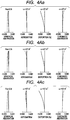
- FIGS. 4Aa, 4Ab, and 4Ac are aberration diagrams of Numerical Embodiment 1 at a wide-angle end at object distances of 7.0 m, infinity, and close range (1.5 m), respectively.
- FIGS. 4Ba, 4Bb, and 4Bc are aberration diagrams of Numerical Embodiment 1 at a telephoto end at object distances of 7.0 m, infinity, and close range (1.5 m), respectively.
- the object distance is a value with reference to the image plane.
- the aberration diagram of each embodiment illustrates spherical aberrations with respect to e-line (full line) and g-line (two-dot and dash line), and illustrates astigmatisms on a meridional image plane (meri) (dot line) with respect to the e-line and on a sagittal image plane (sagi) (solid line) with respect to the e-line.
- Lateral chromatic aberration is indicated with respect to g-line (two-dot and dash line).
- An F number is denoted by Fno
- ⁇ a half angle of field
- the spherical aberration, the astigmatism, the distortion, and the lateral chromatic aberration are indicated in units of 0.4 mm, 0.4 mm, 5%, and 0.05 mm, respectively.
- the aspherical shape is expressed in the following expression where an X axis corresponds to the optical axis, an H axis corresponds to an axis perpendicular to the optical axis, a traveling direction of light corresponds to a positive direction, "R” represents a paraxial curvature radius, "k” represents a conic constant, and "A4", "A6", “A8", “A10", and “A12” each denote an aspherical coefficient.
- X H 2 / R 1 + 1 ⁇ 1 + k H / R 2 + A 4 H 4 + A 6 H 6 + A 8 H 8 + A 10 H 10 + A 12 H 12
- e-Z means “ ⁇ 10 -Z ".
- FIGS. 5A and 5B are lens cross sectional views of a zoom lens according to Embodiment 2 (Numerical Embodiment 2) of the present invention at a wide-angle end in which the object distance is infinity and close range, respectively.
- the zoom lens of this embodiment includes, in order from the object side (left side), a focus lens unit having positive refractive power as the first lens unit U1, a variator having negative refractive power for varying magnification as a second lens unit U2, a compensator having negative refractive power as a third lens unit U3, a stop SP, an imaging lens unit having positive refractive power and an image forming action as a fourth lens unit U4, and an image pickup surface I.
- the second lens unit U2 and the third lens unit U3 constitute the magnification-varying lens unit.
- the second lens unit U2 (variator) varies magnification from the wide-angle end to the telephoto end by moving monotonously on the optical axis toward the image plane side.
- the third lens unit U3 (compensator) moves non-linearly on the optical axis in order to correct image plane variation accompanying the magnification variation.
- a structure of the first lens unit U1 in this embodiment corresponds to first to seventeenth surfaces.
- the first lens unit U1 includes the first sub-lens unit U11 having positive refractive power, the second sub-lens unit U12 having negative refractive power that moves 19.18 mm toward the object side from the object distance of infinity to close range, and the third sub-lens unit U13 having positive refractive power that moves 3.84 mm toward the object side from the object distance of infinity to close range.
- the entire third sub-lens unit U13 corresponds to the sub-third sub-lens unit U13f.
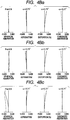
- FIGS. 6Aa, 6Ab, and 6Ac illustrate aberration diagrams of Numerical Embodiment 2 at a wide-angle end at object distances of 7.0 m, infinity, and close range (1.8 m), respectively.
- FIGS. 6Ba, 6Bb, and 6Bc illustrate aberration diagrams of Numerical Embodiment 2 at a telephoto end at object distances of 7.0 m, infinity, and close range (1.8 m), respectively.
- the object distance is a value with reference to the image plane.
- FIGS. 7A and 7B are lens cross sectional views of a zoom lens according to Embodiment 3 (Numerical Embodiment 3) of the present invention at a wide-angle end in which the object distance is infinity and close range, respectively.
- FIGS. 7A and 7B illustrate, in order from the object side (left side), a focus lens unit having positive refractive power as the first lens unit U1, a variator having negative refractive power for varying magnification as a second lens unit U2, a compensator having negative refractive power as a third lens unit U3, a stop SP, an imaging lens unit having positive refractive power and an image forming action as a fourth lens unit U4, and an image pickup surface I.
- the second lens unit U2 and the third lens unit U3 constitute the magnification-varying lens unit.
- the second lens unit U2 (variator) varies magnification from the wide-angle end to the telephoto end by moving monotonously on the optical axis toward the image plane side.
- the third lens unit U3 (compensator) moves non-linearly on the optical axis in order to correct image plane variation accompanying the magnification variation.
- a structure of the first lens unit U1 in this embodiment corresponds to first to seventeenth surfaces.
- the first lens unit U1 includes the first sub-lens unit U11 having positive refractive power, the second sub-lens unit U12 having negative refractive power that moves 9.68 mm toward the object side from the object distance of infinity to the close range, and the third sub-lens unit U13 having positive refractive power.
- a lens unit U13p which is included in the third sub-lens unit U13 and has positive refractive power, moves 3.87 mm toward the object side from the object distance of infinity to close range. Therefore, in this embodiment, the lens unit U13p corresponds to the sub-third sub-lens unit U13f.
- FIGS. 8Aa, 8Ab, and 8Ac are aberration diagrams of Numerical Embodiment 3 at a wide-angle end at object distances of 7.0 m, infinity, and close range (1.8 m), respectively.
- FIGS. 8Ba, 8Bb, and 8Bc are aberration diagrams of Numerical Embodiment 3 at a telephoto end at object distances of 7.0 m, infinity, and close range (1.8 m), respectively.
- the object distance is a value with reference to the image plane.
- FIGS. 9A and 9B are lens cross sectional views of a zoom lens according to Embodiment 4 (Numerical Embodiment 4) of the present invention at a wide-angle end in which the object distance is infinity and close range, respectively.
- the zoom lens of this embodiment includes, in order from the object side, a focus lens unit having positive refractive power as the first lens unit U1, a variator having negative refractive power for varying magnification as a second lens unit U2, a compensator having positive refractive power as a third lens unit U3, a stop SP, an imaging lens unit having positive refractive power and an image forming action as a fourth lens unit U4, a glass block P equivalent to a color separation prism, and an image pickup surface I.
- the second lens unit U2 and the third lens unit U3 constitute the magnification-varying lens unit.
- the second lens unit U2 (variator) varies magnification from the wide-angle end to the telephoto end by moving monotonously on the optical axis toward the image plane side.
- the third lens unit U3 (compensator) moves on the optical axis toward the object side in order to correct image plane variation accompanying the magnification variation.
- a structure of the first lens unit U1 in this embodiment corresponds to first to seventeenth surfaces.
- the first lens unit U1 includes the first sub-lens unit U11 having positive refractive power, the second sub-lens unit U12 having negative refractive power that moves 4.67 mm toward the object side from the object distance of infinity to close range, and the third sub-lens unit U13 having positive refractive power.
- a lens unit U13p which is included in the third sub-lens unit U13 and has positive refractive power, moves 9.33 mm toward the object side from the object distance of infinity to close range. Therefore, in this embodiment, the lens unit U13p corresponds to the sub-third sub-lens unit U13f.
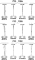
- FIGS. 10Aa, 10Ab, and 10Ac are aberration diagrams of Numerical Embodiment 4 at a wide-angle end at object distances of 12.0 m, infinity, and close range (3.5 m), respectively.
- FIGS. 10Ba, 10Bb, and 10Bc are aberration diagrams of Numerical Embodiment 4 at a telephoto end at object distances of 12.0 m, infinity, and close range (3.5 m), respectively.
- the object distance is a value with reference to the image plane.
- This embodiment satisfies the expressions (1) to (5) and achieves a zoom lens having a high magnification, a small size and light weight, little aberration deviation due to focus adjustment, and little breathing.
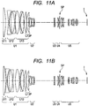
- FIGS. 11A and 11B are lens cross sectional views of a zoom lens according to Embodiment 5 (Numerical Embodiment 5) of the present invention at a wide-angle end in which the object distance is infinity and close range, respectively.
- the zoom lens of this embodiment includes, in order from the object side, a focus lens unit having positive refractive power as the first lens unit U1, a first variator having negative refractive power for varying magnification as a second lens unit U2, a compensator having positive refractive power as a fourth lens unit U4, a stop SP, an imaging lens unit having positive refractive power and an image forming action as a five lens unit U5, and an image pickup surface I.
- the second lens unit U2, the third lens unit U3, and the fourth lens unit U4 constitute the magnification-varying lens unit.
- the second lens unit U2 (first variator) varies magnification from the wide-angle end to the telephoto end by moving monotonously on the optical axis toward the image plane side.
- the third lens unit U3 (second variator) moves on the optical axis so as to vary magnification from the wide-angle end to the telephoto end.
- the fourth lens unit U4 (compensator) moves non-linearly on the optical axis in order to correct image plane variation accompanying magnification-varying.
- the third lens unit U3 may be the compensator and the fourth lens unit U4 may be the second variator.
- a structure of the first lens unit U1 in this embodiment corresponds to first to seventeenth surfaces.
- the first lens unit U1 includes the first sub-lens unit U11 having positive refractive power, the second sub-lens unit U12 having negative refractive power that moves 9.18 mm toward the object side from the object distance of infinity to close range, and the third sub-lens unit U13 having positive refractive power.
- a lens unit U13p which is included in the third sub-lens unit U13 and has positive refractive power, moves 1.38 mm toward the object side from the object distance of infinity to close range. Therefore, in this embodiment, the lens unit U13p corresponds to the sub-third sub-lens unit U13f.
- FIGS. 12Aa, 12Ab, and 12Ac are aberration diagrams of Numerical Embodiment 5 at a wide-angle end at object distances of 7.0 m, infinity, and close range (1.8 m), respectively.
- FIGS. 12Ba, 12Bb, 12Bc are aberration diagrams of Numerical Embodiment 5 at a telephoto end at object distances of 7.0 m, infinity, and close range (1.8 m), respectively.
- the object distance is a value with reference to the image plane.
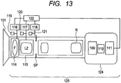
- FIG. 13 is a schematic diagram of an image pickup apparatus according to Embodiment 6 of the present invention using any one of the zoom lens of Embodiments 1 to 5 as an image pickup optical system.
- an image pickup apparatus 125 includes a zoom lens 101 of any one of Embodiments 1 to 5 and a camera 124 that can be attached to and removed from the zoom lens 101.
- the zoom lens 101 includes a first lens unit F including a lens unit for focus adjustment, a magnification-varying lens unit LZ, and a lens unit R for imaging.
- the zoom lens 101 further includes an aperture stop SP.
- the first lens unit F and the magnification-varying lens unit LZ are driven in an optical axis direction respectively by drive mechanisms 114 and 115 such as a helicoid or a cam.
- the drive mechanisms 114 and 115 and the aperture stop SP are electrically driven by motors (drive units) 116 to 118 that are electrically driven, respectively.
- Positions of the first lens unit F and the magnification-varying lens unit LZ on the optical axis and a stop diameter of the aperture stop SP are detected by detectors 119 to 121, respectively, such as an encoder, a potentiometer, or a photo sensor.
- the camera 124 includes a glass block 109 corresponding to an optical filter or a color separation optical system, and a solid-state image pickup element (photoelectric transducer) 110 such as a CCD sensor or a CMOS sensor for receiving light of a subject image formed by the zoom lens 101.
- CPUs 111 and 122 control various drives of the camera 124 and the zoom lens 101, respectively. In this way, through use of the zoom lens of the present invention for a television camera, an image pickup apparatus having high optical performance can be realized.
Landscapes
- Physics & Mathematics (AREA)
- General Physics & Mathematics (AREA)
- Optics & Photonics (AREA)
- Engineering & Computer Science (AREA)
- Multimedia (AREA)
- Signal Processing (AREA)
- Nonlinear Science (AREA)
- Lenses (AREA)
Applications Claiming Priority (1)
| Application Number | Priority Date | Filing Date | Title |
|---|---|---|---|
| JP2011069565A JP5693322B2 (ja) | 2011-03-28 | 2011-03-28 | ズームレンズ及び撮像装置 |
Publications (2)
| Publication Number | Publication Date |
|---|---|
| EP2506060A1 EP2506060A1 (en) | 2012-10-03 |
| EP2506060B1 true EP2506060B1 (en) | 2017-03-22 |
Family
ID=45939097
Family Applications (1)
| Application Number | Title | Priority Date | Filing Date |
|---|---|---|---|
| EP12002247.0A Active EP2506060B1 (en) | 2011-03-28 | 2012-03-27 | Zoom lens and image pickup apparatus including the same |
Country Status (5)
| Country | Link |
|---|---|
| US (1) | US8488253B2 (https=) |
| EP (1) | EP2506060B1 (https=) |
| JP (1) | JP5693322B2 (https=) |
| KR (1) | KR101473690B1 (https=) |
| CN (1) | CN102707417B (https=) |
Families Citing this family (11)
| Publication number | Priority date | Publication date | Assignee | Title |
|---|---|---|---|---|
| CN104199178B (zh) * | 2014-08-06 | 2017-03-29 | 青岛歌尔声学科技有限公司 | 一种变焦镜头 |
| EP3159726B1 (en) * | 2015-10-20 | 2024-07-03 | Canon Kabushiki Kaisha | Zoom lens and image pickup apparatus including the same |
| US10602070B2 (en) | 2016-01-27 | 2020-03-24 | Raytheon Company | Variable magnification active imaging system |
| CN108700729B (zh) * | 2016-01-27 | 2020-10-02 | 富士胶片株式会社 | 变焦透镜及摄像装置 |
| US10382701B2 (en) | 2016-01-27 | 2019-08-13 | Raytheon Company | Active imaging systems and method |
| CN108732718B (zh) * | 2017-04-24 | 2020-09-29 | 沈阳市若明光学科技有限公司 | 成像镜头 |
| CN109387921B (zh) * | 2017-08-11 | 2024-06-18 | 宁波舜宇光电信息有限公司 | 光学镜头、摄像模组及其组装方法 |
| JP7277304B2 (ja) * | 2019-07-30 | 2023-05-18 | キヤノン株式会社 | ズームレンズおよび撮像装置 |
| JP7344715B2 (ja) | 2019-08-16 | 2023-09-14 | キヤノン株式会社 | ズームレンズおよび撮像装置 |
| US11703669B2 (en) * | 2019-12-25 | 2023-07-18 | Canon Kabushiki Kaisha | Zoom lens and image pickup apparatus |
| JP7614874B2 (ja) * | 2021-02-12 | 2025-01-16 | キヤノン株式会社 | ズームレンズおよび撮像装置 |
Family Cites Families (24)
| Publication number | Priority date | Publication date | Assignee | Title |
|---|---|---|---|---|
| JPS63188110A (ja) * | 1987-01-30 | 1988-08-03 | Asahi Optical Co Ltd | 望遠ズ−ムレンズ |
| US5745300A (en) | 1993-02-17 | 1998-04-28 | Canon Kabushiki Kaisha | Zoom lens of the inner focus type |
| JP3495772B2 (ja) | 1993-11-30 | 2004-02-09 | キヤノン株式会社 | ズームレンズ及びそれを有するテレビカメラ |
| JPH085907A (ja) | 1994-06-23 | 1996-01-12 | Nikon Corp | 望遠レンズ光学系 |
| JP3301579B2 (ja) | 1996-03-22 | 2002-07-15 | 富士写真光機株式会社 | インナーフォーカシングタイプのズームレンズ |
| JP3827251B2 (ja) | 1996-07-16 | 2006-09-27 | フジノン株式会社 | ズームレンズ |
| JP3957883B2 (ja) | 1998-06-22 | 2007-08-15 | キヤノン株式会社 | ズームレンズ |
| JP4463909B2 (ja) | 1999-10-19 | 2010-05-19 | キヤノン株式会社 | ズームレンズ |
| US6693750B2 (en) | 2001-09-19 | 2004-02-17 | Nikon Corporation | Zoom lens system |
| DE60308191T2 (de) | 2002-07-22 | 2007-08-23 | Panavision Inc., Woodland Hills | Zoom mit ultrahohem vergrösserungsverhältnis |
| JP4203284B2 (ja) * | 2002-08-27 | 2008-12-24 | 株式会社シグマ | 望遠ズームレンズ |
| JP4208667B2 (ja) | 2002-08-28 | 2009-01-14 | キヤノン株式会社 | ズームレンズおよび撮像装置 |
| JP4626135B2 (ja) | 2002-10-04 | 2011-02-02 | 株式会社ニコン | 大口径比内焦式望遠ズームレンズ |
| JP2004309761A (ja) | 2003-04-07 | 2004-11-04 | Fuji Photo Optical Co Ltd | 広角系ズームレンズ |
| JP4751732B2 (ja) * | 2006-02-10 | 2011-08-17 | Hoya株式会社 | 望遠ズームレンズ系 |
| JP5009571B2 (ja) * | 2006-08-28 | 2012-08-22 | 富士フイルム株式会社 | ズームレンズ |
| JP2008164724A (ja) * | 2006-12-27 | 2008-07-17 | Sony Corp | ズームレンズ及び撮像装置 |
| JP2008203449A (ja) * | 2007-02-19 | 2008-09-04 | Sony Corp | ズームレンズ及び撮像装置 |
| CN100568044C (zh) * | 2007-04-26 | 2009-12-09 | 亚洲光学股份有限公司 | 变焦镜头 |
| CN101339290B (zh) * | 2007-07-02 | 2010-12-01 | 大立光电股份有限公司 | 变焦镜头 |
| KR20090126817A (ko) * | 2008-06-05 | 2009-12-09 | 삼성디지털이미징 주식회사 | 망원 줌 렌즈 |
| JP5517525B2 (ja) | 2009-08-17 | 2014-06-11 | キヤノン株式会社 | ズームレンズ及びそれを有する撮像装置 |
| JP5350129B2 (ja) | 2009-08-17 | 2013-11-27 | キヤノン株式会社 | ズームレンズ及びそれを有する撮像装置 |
| JP5344605B2 (ja) | 2009-08-17 | 2013-11-20 | キヤノン株式会社 | ズームレンズ及びそれを有する撮像装置 |
-
2011
- 2011-03-28 JP JP2011069565A patent/JP5693322B2/ja active Active
-
2012
- 2012-03-20 KR KR1020120028139A patent/KR101473690B1/ko not_active Expired - Fee Related
- 2012-03-23 US US13/428,200 patent/US8488253B2/en active Active
- 2012-03-23 CN CN201210079179.5A patent/CN102707417B/zh active Active
- 2012-03-27 EP EP12002247.0A patent/EP2506060B1/en active Active
Non-Patent Citations (1)
| Title |
|---|
| None * |
Also Published As
| Publication number | Publication date |
|---|---|
| US20120250162A1 (en) | 2012-10-04 |
| JP5693322B2 (ja) | 2015-04-01 |
| CN102707417A (zh) | 2012-10-03 |
| JP2012203297A (ja) | 2012-10-22 |
| KR101473690B1 (ko) | 2014-12-17 |
| KR20120110012A (ko) | 2012-10-09 |
| CN102707417B (zh) | 2014-11-05 |
| EP2506060A1 (en) | 2012-10-03 |
| US8488253B2 (en) | 2013-07-16 |
Similar Documents
| Publication | Publication Date | Title |
|---|---|---|
| EP2506060B1 (en) | Zoom lens and image pickup apparatus including the same | |
| EP2871510B1 (en) | Zoom lens and image pickup apparatus including the same | |
| EP2650712B1 (en) | Zoom lens of the telephoto type having four lens groups | |
| US8659832B2 (en) | Zoom lens and image pickup apparatus including the same | |
| US9329372B2 (en) | Zoom lens and image pickup apparatus having the same | |
| EP2527899B1 (en) | Zoom lens of the telephoto type and having four lens groups | |
| EP2824496B1 (en) | Zoom lens and image pickup apparatus including the same | |
| JP5489480B2 (ja) | ズームレンズ及びそれを有する撮像装置 | |
| US8934047B2 (en) | Zoom lens and image pickup apparatus including the same | |
| EP3361301B1 (en) | Zoom lens and image pickup apparatus having the same | |
| EP2620797B1 (en) | Zoom lens of the telephoto-type and having five lens-groups | |
| JP5430332B2 (ja) | ズームレンズ及びそれを有する撮像装置 | |
| EP3945357B1 (en) | Zoom lens | |
| EP2921896A1 (en) | Zoom lens and image pickup apparatus having the same | |
| US20120262608A1 (en) | Zoom lens and image pickup apparatus including the same | |
| JP2011123337A5 (https=) | ||
| US11275235B2 (en) | Zoom lens and image pickup apparatus | |
| EP2506059B1 (en) | Zoom lens and image pickup apparatus including the same | |
| US8599494B2 (en) | Zoom lens and image pickup apparatus having the same | |
| EP4040211B1 (en) | Zoom lens and image pickup apparatus | |
| US8593736B2 (en) | Zoom lens and image pickup apparatus including the same | |
| JP2016200729A (ja) | ズームレンズ | |
| US20230185065A1 (en) | Zoom lens and image pickup apparatus | |
| US20260118649A1 (en) | Zoom lens and image pickup apparatus | |
| US20240248287A1 (en) | Zoom lens and imaging apparatus including the same |
Legal Events
| Date | Code | Title | Description |
|---|---|---|---|
| PUAI | Public reference made under article 153(3) epc to a published international application that has entered the european phase |
Free format text: ORIGINAL CODE: 0009012 |
|
| AK | Designated contracting states |
Kind code of ref document: A1 Designated state(s): AL AT BE BG CH CY CZ DE DK EE ES FI FR GB GR HR HU IE IS IT LI LT LU LV MC MK MT NL NO PL PT RO RS SE SI SK SM TR |
|
| AX | Request for extension of the european patent |
Extension state: BA ME |
|
| RAP1 | Party data changed (applicant data changed or rights of an application transferred) |
Owner name: CANON KABUSHIKI KAISHA |
|
| 17P | Request for examination filed |
Effective date: 20130403 |
|
| 17Q | First examination report despatched |
Effective date: 20160202 |
|
| GRAP | Despatch of communication of intention to grant a patent |
Free format text: ORIGINAL CODE: EPIDOSNIGR1 |
|
| RIN1 | Information on inventor provided before grant (corrected) |
Inventor name: USUI, FUMIAKI Inventor name: WAKAZONO, TSUYOSHI |
|
| INTG | Intention to grant announced |
Effective date: 20160929 |
|
| GRAJ | Information related to disapproval of communication of intention to grant by the applicant or resumption of examination proceedings by the epo deleted |
Free format text: ORIGINAL CODE: EPIDOSDIGR1 |
|
| GRAR | Information related to intention to grant a patent recorded |
Free format text: ORIGINAL CODE: EPIDOSNIGR71 |
|
| GRAS | Grant fee paid |
Free format text: ORIGINAL CODE: EPIDOSNIGR3 |
|
| GRAA | (expected) grant |
Free format text: ORIGINAL CODE: 0009210 |
|
| INTC | Intention to grant announced (deleted) | ||
| INTG | Intention to grant announced |
Effective date: 20170208 |
|
| AK | Designated contracting states |
Kind code of ref document: B1 Designated state(s): AL AT BE BG CH CY CZ DE DK EE ES FI FR GB GR HR HU IE IS IT LI LT LU LV MC MK MT NL NO PL PT RO RS SE SI SK SM TR |
|
| REG | Reference to a national code |
Ref country code: GB Ref legal event code: FG4D |
|
| REG | Reference to a national code |
Ref country code: CH Ref legal event code: EP |
|
| REG | Reference to a national code |
Ref country code: AT Ref legal event code: REF Ref document number: 878350 Country of ref document: AT Kind code of ref document: T Effective date: 20170415 |
|
| REG | Reference to a national code |
Ref country code: IE Ref legal event code: FG4D |
|
| REG | Reference to a national code |
Ref country code: DE Ref legal event code: R096 Ref document number: 602012030026 Country of ref document: DE |
|
| REG | Reference to a national code |
Ref country code: NL Ref legal event code: MP Effective date: 20170322 |
|
| PG25 | Lapsed in a contracting state [announced via postgrant information from national office to epo] |
Ref country code: LT Free format text: LAPSE BECAUSE OF FAILURE TO SUBMIT A TRANSLATION OF THE DESCRIPTION OR TO PAY THE FEE WITHIN THE PRESCRIBED TIME-LIMIT Effective date: 20170322 Ref country code: NO Free format text: LAPSE BECAUSE OF FAILURE TO SUBMIT A TRANSLATION OF THE DESCRIPTION OR TO PAY THE FEE WITHIN THE PRESCRIBED TIME-LIMIT Effective date: 20170622 Ref country code: GR Free format text: LAPSE BECAUSE OF FAILURE TO SUBMIT A TRANSLATION OF THE DESCRIPTION OR TO PAY THE FEE WITHIN THE PRESCRIBED TIME-LIMIT Effective date: 20170623 Ref country code: HR Free format text: LAPSE BECAUSE OF FAILURE TO SUBMIT A TRANSLATION OF THE DESCRIPTION OR TO PAY THE FEE WITHIN THE PRESCRIBED TIME-LIMIT Effective date: 20170322 Ref country code: FI Free format text: LAPSE BECAUSE OF FAILURE TO SUBMIT A TRANSLATION OF THE DESCRIPTION OR TO PAY THE FEE WITHIN THE PRESCRIBED TIME-LIMIT Effective date: 20170322 |
|
| REG | Reference to a national code |
Ref country code: LT Ref legal event code: MG4D |
|
| REG | Reference to a national code |
Ref country code: AT Ref legal event code: MK05 Ref document number: 878350 Country of ref document: AT Kind code of ref document: T Effective date: 20170322 |
|
| PG25 | Lapsed in a contracting state [announced via postgrant information from national office to epo] |
Ref country code: RS Free format text: LAPSE BECAUSE OF FAILURE TO SUBMIT A TRANSLATION OF THE DESCRIPTION OR TO PAY THE FEE WITHIN THE PRESCRIBED TIME-LIMIT Effective date: 20170322 Ref country code: BG Free format text: LAPSE BECAUSE OF FAILURE TO SUBMIT A TRANSLATION OF THE DESCRIPTION OR TO PAY THE FEE WITHIN THE PRESCRIBED TIME-LIMIT Effective date: 20170622 Ref country code: SE Free format text: LAPSE BECAUSE OF FAILURE TO SUBMIT A TRANSLATION OF THE DESCRIPTION OR TO PAY THE FEE WITHIN THE PRESCRIBED TIME-LIMIT Effective date: 20170322 Ref country code: LV Free format text: LAPSE BECAUSE OF FAILURE TO SUBMIT A TRANSLATION OF THE DESCRIPTION OR TO PAY THE FEE WITHIN THE PRESCRIBED TIME-LIMIT Effective date: 20170322 |
|
| PG25 | Lapsed in a contracting state [announced via postgrant information from national office to epo] |
Ref country code: NL Free format text: LAPSE BECAUSE OF FAILURE TO SUBMIT A TRANSLATION OF THE DESCRIPTION OR TO PAY THE FEE WITHIN THE PRESCRIBED TIME-LIMIT Effective date: 20170322 |
|
| PG25 | Lapsed in a contracting state [announced via postgrant information from national office to epo] |
Ref country code: CZ Free format text: LAPSE BECAUSE OF FAILURE TO SUBMIT A TRANSLATION OF THE DESCRIPTION OR TO PAY THE FEE WITHIN THE PRESCRIBED TIME-LIMIT Effective date: 20170322 Ref country code: ES Free format text: LAPSE BECAUSE OF FAILURE TO SUBMIT A TRANSLATION OF THE DESCRIPTION OR TO PAY THE FEE WITHIN THE PRESCRIBED TIME-LIMIT Effective date: 20170322 Ref country code: EE Free format text: LAPSE BECAUSE OF FAILURE TO SUBMIT A TRANSLATION OF THE DESCRIPTION OR TO PAY THE FEE WITHIN THE PRESCRIBED TIME-LIMIT Effective date: 20170322 Ref country code: SK Free format text: LAPSE BECAUSE OF FAILURE TO SUBMIT A TRANSLATION OF THE DESCRIPTION OR TO PAY THE FEE WITHIN THE PRESCRIBED TIME-LIMIT Effective date: 20170322 Ref country code: RO Free format text: LAPSE BECAUSE OF FAILURE TO SUBMIT A TRANSLATION OF THE DESCRIPTION OR TO PAY THE FEE WITHIN THE PRESCRIBED TIME-LIMIT Effective date: 20170322 Ref country code: AT Free format text: LAPSE BECAUSE OF FAILURE TO SUBMIT A TRANSLATION OF THE DESCRIPTION OR TO PAY THE FEE WITHIN THE PRESCRIBED TIME-LIMIT Effective date: 20170322 Ref country code: IT Free format text: LAPSE BECAUSE OF FAILURE TO SUBMIT A TRANSLATION OF THE DESCRIPTION OR TO PAY THE FEE WITHIN THE PRESCRIBED TIME-LIMIT Effective date: 20170322 |
|
| REG | Reference to a national code |
Ref country code: CH Ref legal event code: PL |
|
| PG25 | Lapsed in a contracting state [announced via postgrant information from national office to epo] |
Ref country code: PT Free format text: LAPSE BECAUSE OF FAILURE TO SUBMIT A TRANSLATION OF THE DESCRIPTION OR TO PAY THE FEE WITHIN THE PRESCRIBED TIME-LIMIT Effective date: 20170724 Ref country code: IS Free format text: LAPSE BECAUSE OF FAILURE TO SUBMIT A TRANSLATION OF THE DESCRIPTION OR TO PAY THE FEE WITHIN THE PRESCRIBED TIME-LIMIT Effective date: 20170722 Ref country code: SM Free format text: LAPSE BECAUSE OF FAILURE TO SUBMIT A TRANSLATION OF THE DESCRIPTION OR TO PAY THE FEE WITHIN THE PRESCRIBED TIME-LIMIT Effective date: 20170322 Ref country code: PL Free format text: LAPSE BECAUSE OF FAILURE TO SUBMIT A TRANSLATION OF THE DESCRIPTION OR TO PAY THE FEE WITHIN THE PRESCRIBED TIME-LIMIT Effective date: 20170322 |
|
| REG | Reference to a national code |
Ref country code: IE Ref legal event code: MM4A |
|
| REG | Reference to a national code |
Ref country code: DE Ref legal event code: R097 Ref document number: 602012030026 Country of ref document: DE |
|
| PLBE | No opposition filed within time limit |
Free format text: ORIGINAL CODE: 0009261 |
|
| STAA | Information on the status of an ep patent application or granted ep patent |
Free format text: STATUS: NO OPPOSITION FILED WITHIN TIME LIMIT |
|
| PG25 | Lapsed in a contracting state [announced via postgrant information from national office to epo] |
Ref country code: DK Free format text: LAPSE BECAUSE OF FAILURE TO SUBMIT A TRANSLATION OF THE DESCRIPTION OR TO PAY THE FEE WITHIN THE PRESCRIBED TIME-LIMIT Effective date: 20170322 Ref country code: MC Free format text: LAPSE BECAUSE OF FAILURE TO SUBMIT A TRANSLATION OF THE DESCRIPTION OR TO PAY THE FEE WITHIN THE PRESCRIBED TIME-LIMIT Effective date: 20170322 Ref country code: LU Free format text: LAPSE BECAUSE OF NON-PAYMENT OF DUE FEES Effective date: 20170327 |
|
| REG | Reference to a national code |
Ref country code: FR Ref legal event code: ST Effective date: 20171229 |
|
| 26N | No opposition filed |
Effective date: 20180102 |
|
| PG25 | Lapsed in a contracting state [announced via postgrant information from national office to epo] |
Ref country code: CH Free format text: LAPSE BECAUSE OF NON-PAYMENT OF DUE FEES Effective date: 20170331 Ref country code: LI Free format text: LAPSE BECAUSE OF NON-PAYMENT OF DUE FEES Effective date: 20170331 Ref country code: SI Free format text: LAPSE BECAUSE OF FAILURE TO SUBMIT A TRANSLATION OF THE DESCRIPTION OR TO PAY THE FEE WITHIN THE PRESCRIBED TIME-LIMIT Effective date: 20170322 Ref country code: IE Free format text: LAPSE BECAUSE OF NON-PAYMENT OF DUE FEES Effective date: 20170327 |
|
| REG | Reference to a national code |
Ref country code: BE Ref legal event code: MM Effective date: 20170331 |
|
| PG25 | Lapsed in a contracting state [announced via postgrant information from national office to epo] |
Ref country code: BE Free format text: LAPSE BECAUSE OF NON-PAYMENT OF DUE FEES Effective date: 20170331 Ref country code: FR Free format text: LAPSE BECAUSE OF NON-PAYMENT OF DUE FEES Effective date: 20170522 |
|
| PG25 | Lapsed in a contracting state [announced via postgrant information from national office to epo] |
Ref country code: MT Free format text: LAPSE BECAUSE OF NON-PAYMENT OF DUE FEES Effective date: 20170327 |
|
| PG25 | Lapsed in a contracting state [announced via postgrant information from national office to epo] |
Ref country code: HU Free format text: LAPSE BECAUSE OF FAILURE TO SUBMIT A TRANSLATION OF THE DESCRIPTION OR TO PAY THE FEE WITHIN THE PRESCRIBED TIME-LIMIT; INVALID AB INITIO Effective date: 20120327 |
|
| PG25 | Lapsed in a contracting state [announced via postgrant information from national office to epo] |
Ref country code: CY Free format text: LAPSE BECAUSE OF NON-PAYMENT OF DUE FEES Effective date: 20170322 |
|
| PG25 | Lapsed in a contracting state [announced via postgrant information from national office to epo] |
Ref country code: MK Free format text: LAPSE BECAUSE OF FAILURE TO SUBMIT A TRANSLATION OF THE DESCRIPTION OR TO PAY THE FEE WITHIN THE PRESCRIBED TIME-LIMIT Effective date: 20170322 |
|
| PG25 | Lapsed in a contracting state [announced via postgrant information from national office to epo] |
Ref country code: TR Free format text: LAPSE BECAUSE OF FAILURE TO SUBMIT A TRANSLATION OF THE DESCRIPTION OR TO PAY THE FEE WITHIN THE PRESCRIBED TIME-LIMIT Effective date: 20170322 |
|
| PG25 | Lapsed in a contracting state [announced via postgrant information from national office to epo] |
Ref country code: AL Free format text: LAPSE BECAUSE OF FAILURE TO SUBMIT A TRANSLATION OF THE DESCRIPTION OR TO PAY THE FEE WITHIN THE PRESCRIBED TIME-LIMIT Effective date: 20170322 |
|
| PGFP | Annual fee paid to national office [announced via postgrant information from national office to epo] |
Ref country code: GB Payment date: 20260219 Year of fee payment: 15 |
|
| PGFP | Annual fee paid to national office [announced via postgrant information from national office to epo] |
Ref country code: DE Payment date: 20260219 Year of fee payment: 15 |