EP2506059B1 - Zoom lens and image pickup apparatus including the same - Google Patents
Zoom lens and image pickup apparatus including the same Download PDFInfo
- Publication number
- EP2506059B1 EP2506059B1 EP12001930.2A EP12001930A EP2506059B1 EP 2506059 B1 EP2506059 B1 EP 2506059B1 EP 12001930 A EP12001930 A EP 12001930A EP 2506059 B1 EP2506059 B1 EP 2506059B1
- Authority
- EP
- European Patent Office
- Prior art keywords
- lens unit
- lens
- sub
- refractive power
- focusing
- Prior art date
- Legal status (The legal status is an assumption and is not a legal conclusion. Google has not performed a legal analysis and makes no representation as to the accuracy of the status listed.)
- Active
Links
Images


Classifications
-
- G—PHYSICS
- G02—OPTICS
- G02B—OPTICAL ELEMENTS, SYSTEMS OR APPARATUS
- G02B15/00—Optical objectives with means for varying the magnification
- G02B15/14—Optical objectives with means for varying the magnification by axial movement of one or more lenses or groups of lenses relative to the image plane for continuously varying the equivalent focal length of the objective
- G02B15/144—Optical objectives with means for varying the magnification by axial movement of one or more lenses or groups of lenses relative to the image plane for continuously varying the equivalent focal length of the objective having four groups only
- G02B15/1441—Optical objectives with means for varying the magnification by axial movement of one or more lenses or groups of lenses relative to the image plane for continuously varying the equivalent focal length of the objective having four groups only the first group being positive
- G02B15/144113—Optical objectives with means for varying the magnification by axial movement of one or more lenses or groups of lenses relative to the image plane for continuously varying the equivalent focal length of the objective having four groups only the first group being positive arranged +-++
-
- G—PHYSICS
- G02—OPTICS
- G02B—OPTICAL ELEMENTS, SYSTEMS OR APPARATUS
- G02B15/00—Optical objectives with means for varying the magnification
- G02B15/14—Optical objectives with means for varying the magnification by axial movement of one or more lenses or groups of lenses relative to the image plane for continuously varying the equivalent focal length of the objective
- G02B15/16—Optical objectives with means for varying the magnification by axial movement of one or more lenses or groups of lenses relative to the image plane for continuously varying the equivalent focal length of the objective with interdependent non-linearly related movements between one lens or lens group, and another lens or lens group
- G02B15/163—Optical objectives with means for varying the magnification by axial movement of one or more lenses or groups of lenses relative to the image plane for continuously varying the equivalent focal length of the objective with interdependent non-linearly related movements between one lens or lens group, and another lens or lens group having a first movable lens or lens group and a second movable lens or lens group, both in front of a fixed lens or lens group
- G02B15/167—Optical objectives with means for varying the magnification by axial movement of one or more lenses or groups of lenses relative to the image plane for continuously varying the equivalent focal length of the objective with interdependent non-linearly related movements between one lens or lens group, and another lens or lens group having a first movable lens or lens group and a second movable lens or lens group, both in front of a fixed lens or lens group having an additional fixed front lens or group of lenses
- G02B15/17—Optical objectives with means for varying the magnification by axial movement of one or more lenses or groups of lenses relative to the image plane for continuously varying the equivalent focal length of the objective with interdependent non-linearly related movements between one lens or lens group, and another lens or lens group having a first movable lens or lens group and a second movable lens or lens group, both in front of a fixed lens or lens group having an additional fixed front lens or group of lenses arranged +--
Definitions
- the present invention relates to a zoom lens suitable for a television camera, a motion-picture camera, a video camera, a photography camera, and a digital camera, and more particularly, to a zoom lens having a high magnification, a small size and light weight, and little aberration deviation due to focus adjustment, and to an image pickup apparatus including the zoom lens.
- Japanese Patent Application Laid-Open No. 2004-309761 discloses a zoom lens in which a focus lens unit having positive refractive power as a whole includes, in order from an object side, a first lens unit having negative refractive power, a second lens unit having negative refractive power, and a third lens unit having positive refractive power.
- Japanese Patent Application Laid-Open No. 2004-309761 proposes a method in which the second lens moves to the object side in focus adjustment to an object at a short distance.
- Japanese Patent Application Laid-Open No. 2004-85846 discloses a zoom lens in which a focus lens unit having positive refractive power as a whole includes, in order from the object side, a first lens unit having positive refractive power, a second lens unit having negative refractive power, and a third lens unit having positive refractive power. Further, Japanese Patent Application Laid-Open No. 2004-85846 proposes a method in which the third lens unit moves to the object side in focus adjustment to an object at a short distance.
- the zoom lens used for a television camera, a motion-picture camera, or the like is desired to achieve a higher magnification as well as a small size and light weight in order to secure mobility and to improve flexibility of photography.
- the zoom lens is required to have high performance with little aberration deviation due to focus adjustment.
- the focus adjustment method of Japanese Patent Application Laid-Open No. 2004-309761 is suitable for a wide-angle zoom lens, but is difficult to achieve a high magnification.
- a zoom ratio is approximately three.
- a diameter or an entire length of the first lens unit is increased.
- the focus adjustment method of Japanese Patent Application Laid-Open No. 2004-85846 is suitable for a telephoto zoom lens, but is difficult to achieve a high magnification.
- a zoom ratio is approximately 2.5.
- a diameter or an entire length of the first lens unit is increased.
- US 5,610,769 A discloses an optical system which includes, in the following order from the object side, a first lens unit having a positive refractive power, a second lens unit having a negative refractive power, the second lens unit comprising, in the following order from the object side, a front lens group of a negative refractive power and a rear lens group of a negative refractive power, and a third lens unit having a positive refractive power.
- focusing to a short-distance object is attained by moving the second lens unit toward the image side.
- the present invention provides a zoom lens having a focus adjustment method with little aberration deviation due to focus adjustment, and an image pickup apparatus including the zoom lens.
- the exemplary embodiments of the present invention provide the zoom lens claimed in claim 1 and the image pickup apparatus claimed in claim 4.
- the other claims relate to further developments.
- the exemplary embodiments of invention provide the zoom lens claimed in claim 1 and the apparatus claimed in claim 4.
- the other claims relate to further developments.
- the exemplary embodiment of the present invention it is possible to provide a zoom lens having a focus adjustment method with little aberration deviation due to focus adjustment, and an image pickup apparatus including the zoom lens.
- the present invention defines the structure of a first lens unit and a focus adjustment method for achieving a high performance zoom lens, which has a high magnification, a small size and light weight, and little aberration deviation due to focus adjustment.
- the aberration deviation due to focus adjustment means a variation of field curvature from an object distance of infinity to a closest focusing distance.
- the zoom lens according to the present invention includes, in order from an object side, a first lens unit having positive refractive power which does not move for varying magnification, a magnification-varying lens unit including at least two lens units which move for varying magnification, an aperture stop, and an imaging lens unit having positive refractive power which does not move for varying magnification.
- a first lens unit U1 includes, in order from the object side, a first sub-lens unit having positive refractive power, a second sub-lens unit having negative refractive power, and a third sub-lens unit having positive refractive power. The second sub-lens unit is driven to the object side so as to perform focus adjustment to an object at a short distance.
- the zoom lens satisfies the following conditional expressions: 0.07 ⁇ f 1 / f 11 ⁇ ⁇ 0.35 0.2 ⁇ f 1 / ft ⁇ 1.0 where f1 represents a focal length of the first lens unit, f11 represents a focal length of the first sub-lens unit, represents and ft represents a focal length of the entire system of the zoom lens at a telephoto end.
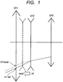
- FIG. 1 An optical action of the present invention is described with reference to FIG. 1 .
- FIG. 1 is a conceptual diagram of an off-axis optical path of the first lens unit at an arbitrary zoom position at an object distance of infinity and closest focusing distance.
- the left side is the object side
- the right side is an image plane side.
- FIG. 1 illustrates, in order from the object side, a first sub-lens unit U11 having positive refractive power, a second sub-lens unit U12 having negative refractive power, and a third sub-lens unit U13 having positive refractive power.
- the zoom lens satisfies the following relationship: h 11 ⁇ inf > h 11 ⁇ mod where hllinf represents a height of an off-axis light beam of the first sub-lens unit U11 at the object distance of infinity, and h11mod represents a height of the off-axis light beam of the first sub-lens unit U11 at the object distance of closest focusing distance.
- the height of the off-axis incident light beam passing through the first sub-lens unit U11 is lower at the object distance of closest focusing distance than at the object distance of infinity. According to this effect, when the object distance varies from infinity to closest focusing distance, the field curvature varies to the over side (side away from the object side). On the other hand, when the second sub-lens unit U12 is driven to the object side so that the object distance varies from infinity to closest focusing distance, the field curvature varies to the under side (object side) on the closest focusing distance side.
- the expression (1) defines a ratio between the focal length f1 of the first lens unit U1 and the focal length f11 of the first sub-lens unit U11. 0.07 ⁇ f 1 / f 11 ⁇ 0.35
- the expression (1) When the expression (1) is satisfied, the aberration deviation due to focus adjustment can be suppressed.
- the upper limit of the expression (1) is not satisfied, the power of the first sub-lens unit U11 becomes too strong with respect to the first lens unit U1, and hence the drive amount of the second sub-lens unit U12 is increased. Thus, it becomes difficult to suppress the aberration deviation due to focus adjustment and to realize a small size and light weight.
- the lower limit of the expression (1) is not satisfied, the power of the first sub-lens unit U11 with respect to the first lens unit U1 becomes too weak, and hence the effect of suppressing field curvature variation of the first sub-lens unit U11 in focus adjustment is eliminated. Further, it is more preferred to set the conditional expression (1) as follows. 0.11 ⁇ f 1 / f 11 ⁇ 0.28
- the expression (2) defines a ratio between the focal length f1 of the first lens unit U1 and the focal length ft of the entire system of the zoom lens at the telephoto end. 0.2 ⁇ f 1 / ft ⁇ 1.0
- the expression (2) When the expression (2) is satisfied, it is possible to achieve both a high magnification and suppression of the aberration deviation due to focus adjustment.
- the focal length f1 of the first lens unit U1 with respect to the focal length ft at the telephoto end in the entire system of the zoom lens becomes too long.
- An object point position of the magnification-varying lens unit becomes far when the focal length of the first lens unit U1 becomes long, and hence a move amount for varying magnification is increased, with the result that it becomes difficult to realize high magnification.
- the power of the first lens unit U1 with respect to the focal length ft at the telephoto end in the entire system of the zoom lens becomes too strong, and hence it becomes difficult to suppress various aberrations due to the first lens unit U1. Further, it is more preferred to set the conditional expression (2) as follows. 0.35 ⁇ f 1 / ft ⁇ 0.7
- power of the second sub-lens unit U12 and power of the third sub-lens unit U13 of the zoom lens are defined, in order to achieve a high performance zoom lens having a high magnification, a small size and light weight, and little aberration deviation due to focus adjustment. Further, the following conditional expression is satisfied: ⁇ 2.5 ⁇ f 12 / f 13 ⁇ ⁇ 0.8 where f12 represents a focal length of the second sub-lens unit U12, and f13 represents a focal length of the third sub-lens unit U13.
- the expression (3) defines a ratio between the focal length f12 of the second sub-lens unit U12 and the focal length f13 of the third sub-lens unit U13.
- the present invention defines the following condition for using the zoom lens effectively in particular: 0.7 ⁇ fw / IS ⁇ 2.4 where fw represents a focal length of the entire system of the zoom lens at the wide-angle end, and IS represents an image size of the image pickup element.
- the expression (4) When the expression (4) is satisfied, it is possible to achieve a small size and light weight as well as suppression of aberration deviation due to focus adjustment.
- the focal length fw of the entire system of the zoom lens at the wide-angle end becomes too long.
- the focal length fw of the entire system of the zoom lens at the wide-angle end becomes too short. Therefore, an incident height of an off-axis light beam of the first sub-lens unit U11 increases, and hence the lens outer diameter becomes large. Note that, it is preferred that such a magnification-varying ratio of the zoom lens that the zoom lens of the present invention is used effectively in particular be four or larger.
- a zoom lens and an image pickup apparatus including the zoom lens according to embodiments of the present invention are described below.
- FIGS. 2A and 2B are lens cross sectional views of a zoom lens according to Embodiment 1 (Numerical Embodiment 1) of the present invention at a wide-angle end when focusing at infinity and closest focusing distance, respectively.
- the zoom lens of this embodiment includes, in order from the object side (left side), a focus lens unit having positive refractive power as the first lens unit U1, a variator having negative refractive power for varying magnification as a second lens unit U2, a compensator having negative refractive power as a third lens unit U3, a stop SP, an imaging lens unit having positive refractive power and an image forming action as a fourth lens unit U4, and an image pickup surface I.
- the second lens unit U2 and the third lens unit U3 constitute the magnification-varying lens unit.
- the second lens unit U2 (variator) varies magnification from the wide-angle end to the telephoto end by moving monotonously on the optical axis toward the image plane side.
- the third lens unit U3 (compensator) moves non-linearly on the optical axis in order to correct image plane variation accompanying the magnification variation.
- the first lens unit U1 in this embodiment corresponds to first to seventeenth surfaces.
- the first lens unit U1 includes the first sub-lens unit U11 having positive refractive power, the second sub-lens unit U12 having negative refractive power that moves toward the object side from the object distance of infinity to closest focusing distance, and the third sub-lens unit U13 having positive refractive power.
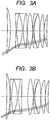
- FIGS. 3A and 3B respectively are optical path diagrams of the first lens unit U1 of Embodiment 1 of the present invention.
- the first sub-lens unit U11 it is understood that the height of the off-axis incident light beam when focusing at infinity ( FIG. 3A ) is larger than the height of the off-axis incident light beam when focusing at closest focusing distance ( FIG. 3B ).
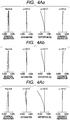
- FIGS. 4Aa to 4Ac are aberration diagrams of Numerical Embodiment 1 at a wide-angle end when focusing at object distances of 7.0 m, infinity, and closest focusing distance (1.5 m), respectively.
- FIGS. 4Ba to 4Bc are aberration diagrams of Numerical Embodiment 1 at a telephoto end when focusing at object distances of 7.0 m, infinity, and closest focusing distance (1.5 m), respectively.
- the object distance is a value with reference to the image plane.
- the aberration diagram of each embodiment illustrates spherical aberrations with respect to e-line (solid line) and g-line (two-dot and dash line), and illustrates astigmatisms on a meridional image plane (meri) (dot line) with respect to the e-line and on a sagittal image plane (sagi) (solid line) with respect to the e-line.
- Lateral chromatic aberration is indicated with respect to g-line (two-dot and dash line).
- An F number is denoted by Fno
- ⁇ a half angle of field
- the spherical aberration, the astigmatism, the distortion, and the lateral chromatic aberration are indicated in units of 0.4 mm, 0.4 mm, 5%, and 0.05 mm, respectively.
- e-Z means “ ⁇ 10 -Z ".
- FIGS. 5A and 5B are lens cross sectional views of a zoom lens according to Embodiment 2 (Numerical Embodiment 2) of the present invention at a wide-angle end when focusing at infinity and closest focusing distance, respectively.
- the zoom lens of this embodiment includes, in order from the object side (left side), a focus lens unit having positive refractive power as the first lens unit U1, a variator having negative refractive power for varying magnification as a second lens unit U2, a compensator having negative refractive power as a third lens unit U3, a stop SP, an imaging lens unit having positive refractive power and an image forming action as a fourth lens unit U4, and an image pickup surface I.
- the second lens unit U2 and the third lens unit U3 constitute the magnification-varying lens unit.
- the second lens unit U2 (variator) varies magnification from the wide-angle end to the telephoto end by moving monotonously on the optical axis toward the image plane side.
- the third lens unit U3 (compensator) moves non-linearly on the optical axis in order to correct image plane variation accompanying the magnification variation.
- the first lens unit U1 in this embodiment corresponds to first to seventeenth surfaces.
- the first lens unit U1 includes the first sub-lens unit U11 having positive refractive power, the second sub-lens unit U12 having negative refractive power that moves toward the object side from the object distance of infinity to closest focusing distance, and the third sub-lens unit U13 having positive refractive power.
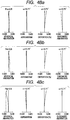
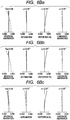
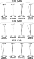
- FIGS. 6Aa to 6Ac illustrate aberration diagrams of Numerical Embodiment 2 at a wide-angle end when focusing at object distances of 7.0 m, infinity, and closest focusing distance (1.8 m), respectively.
- FIGS. 6Ba to 6Bc illustrate aberration diagrams of Numerical Embodiment 2 at a telephoto end when focusing at object distances of 7.0 m, infinity, and closest focusing distance (1.8 m), respectively.
- the object distance is a value with reference to the image plane.
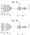
- FIGS. 7A and 7B are lens cross sectional views of a zoom lens according to Embodiment 3 (Numerical Embodiment 3) of the present invention at a wide-angle end when focusing at infinity and closest focusing distance, respectively.
- FIGS. 7A and 7B illustrate, in order from the object side (left side), a focus lens unit having positive refractive power as the first lens unit U1, a variator having negative refractive power for varying magnification as a second lens unit U2, a compensator having negative refractive power as a third lens unit U3, a stop SP, an imaging lens unit having positive refractive power and an image forming action as a fourth lens unit U4, and an image pickup surface I.
- the second lens unit U2 and the third lens unit U3 constitute the magnification-varying lens unit.
- the second lens unit U2 (variator) varies magnification from the wide-angle end to the telephoto end by moving monotonously on the optical axis toward the image plane side.
- the third lens unit U3 (compensator) moves non-linearly on the optical axis in order to correct image plane variation accompanying the magnification variation.
- the first lens unit U1 in this embodiment corresponds to first to eighteenth surfaces.
- the first lens unit U1 includes the first sub-lens unit U11 having positive refractive power, the second sub-lens unit U12 having negative refractive power that moves toward the object side from the object distance of infinity to the closest focusing distance, and the third sub-lens unit U13 having positive refractive power.
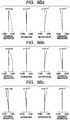
- FIGS. 8Aa to 8Ac are aberration diagrams of Numerical Embodiment 3 at a wide-angle end when focusing at object distances of 7.0 m, infinity, and closest focusing distance (1.8 m), respectively.
- FIGS. 8Ba to 8Bc are aberration diagrams of Numerical Embodiment 3 at a telephoto end when focusing at object distances of 7.0 m, infinity, and closest focusing distance (1.8 m), respectively.
- the object distance is a value with reference to the image plane.
- FIGS. 9A and 9B are lens cross sectional views of a zoom lens according to Embodiment 4 (Numerical Embodiment 4) of the present invention at a wide-angle end when focusing at infinity and closest focusing distance, respectively.
- the zoom lens of this embodiment includes, in order from the object side (left side), a focus lens unit having positive refractive power as the first lens unit U1, a variator having negative refractive power for varying magnification as a second lens unit U2, a compensator having positive refractive power as a third lens unit U3, a stop SP, an imaging lens unit having positive refractive power and an image forming action as a fourth lens unit U4, a glass block P equivalent to a color separation prism, and an image pickup surface I.
- the second lens unit U2 and the third lens unit U3 constitute the magnification-varying lens unit.
- the second lens unit U2 (variator) varies magnification from the wide-angle end to the telephoto end by moving monotonously on the optical axis toward the image plane side.
- the third lens unit U3 (compensator) moves on the optical axis toward the object side in order to correct image plane variation accompanying the magnification variation.
- the first lens unit U1 in this embodiment corresponds to first to eighteenth surfaces.
- the first lens unit U1 includes the first sub-lens unit U11 having positive refractive power, the second sub-lens unit U12 having negative refractive power that moves toward the object side from the object distance of infinity to closest focusing distance, and the third sub-lens unit U13 having positive refractive power.
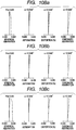
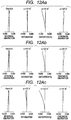
- FIGS. 10Aa to 10Ac are aberration diagrams of Numerical Embodiment 4 at a wide-angle end when focusing at object distances of 12.0 m, infinity, and closest focusing distance (3.5 m), respectively.
- FIGS. 10Ba to 10Bc are aberration diagrams of Numerical Embodiment 4 when focusing at a telephoto end at object distances of 12.0 m, infinity, and closest focusing distance (3.5 m), respectively.
- the object distance is a value with reference to the image plane.
- FIGS. 11A and 11B are lens cross sectional views of a zoom lens according to Embodiment 5 (Numerical Embodiment 5) of the present invention at a wide-angle end when focusing at infinity and closest focusing distance, respectively.
- the zoom lens of this embodiment includes, in order from the object side (left side), a focus lens unit having positive refractive power as the first lens unit U1, a first variator having negative refractive power for varying magnification as a second lens unit U2, a second variator having negative refractive power for varying magnification as a third lens unit U3, a compensator having positive refractive power as a fourth lens unit U4, a stop SP, an imaging lens unit having positive refractive power and an image forming action as a fifth lens unit U5, and an image pickup surface I.
- the second lens unit U2, the third lens unit U3, and the fourth lens unit U4 constitute the magnification-varying lens unit.
- the second lens unit U2 (first variator) varies magnification from the wide-angle end to the telephoto end by moving monotonously on the optical axis toward the image plane side.
- the third lens unit U3 (second variator) moves on the optical axis so as to vary magnification from the wide-angle end to the telephoto end.
- the fourth lens unit U4 (compensator) moves non-linearly on the optical axis in order to correct image plane variation accompanying magnification-varying.
- the third lens unit U3 may be the compensator and the fourth lens unit U4 may be the second variator.
- the first lens unit U1 in this embodiment corresponds to first to eighteenth surfaces.
- the first lens unit U1 includes the first sub-lens unit U11 having positive refractive power, the second sub-lens unit U12 having negative refractive power that moves toward the object side from the object distance of infinity to closest focusing distance, and the third sub-lens unit U13 having positive refractive power.
- FIGS. 12Aa to 12Ac are aberration diagrams of Numerical Embodiment 5 at a wide-angle end when focusing at object distances of 7.0 m, infinity, and closest focusing distance (1.8 m), respectively.
- FIGS. 12Ba to 12Bc are aberration diagrams of Numerical Embodiment 5 at a telephoto end when focusing at object distances of 7.0 m, infinity, and closest focusing distance (1.8 m), respectively.
- the object distance is a value with reference to the image plane.
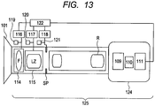
- FIG. 13 is a schematic diagram of an image pickup apparatus according to Embodiment 6 of the present invention using any one of the zoom lenses of Embodiments 1 to 5 as an image pickup optical system.
- An image pickup apparatus 125 of the present invention includes a zoom lens 101 of any one of Embodiments 1 to 5 and a camera 124.
- the zoom lens 101 can be attached to and removed from the camera 124 and includes a first lens unit F including a lens unit for focus adjustment, a magnification-varying lens unit LZ, and a lens unit R for imaging.
- the zoom lens 101 further includes an aperture stop SP.
- the first lens unit F and the magnification-varying lens unit LZ are driven in an optical axis direction respectively by drive mechanisms 114 and 115 such as a helicoid or a cam.
- the drive mechanisms 114 and 115 and the aperture stop SP are electrically driven by motors (drive units) 116 to 118, respectively. Positions of the first lens unit F and the magnification-varying lens unit LZ on the optical axis and a stop diameter of the aperture stop SP are detected by detectors 119 to 121, respectively, such as an encoder, a potentiometer, or a photo sensor.
- the camera 124 includes a glass block 109 corresponding to an optical filter or a color separation optical system, and a solid-state image pickup element (photoelectric transducer) 110 such as a CCD sensor or a CMOS sensor for receiving light of a subject image formed by the zoom lens 101.
- CPUs 111 and 122 control various drives of the camera 124 and the zoom lens 101, respectively. In this way, through use of the zoom lens of the present invention for a television camera, an image pickup apparatus having high optical performance can be realized.
Landscapes
- Physics & Mathematics (AREA)
- General Physics & Mathematics (AREA)
- Optics & Photonics (AREA)
- Nonlinear Science (AREA)
- Lenses (AREA)
Description
- The present invention relates to a zoom lens suitable for a television camera, a motion-picture camera, a video camera, a photography camera, and a digital camera, and more particularly, to a zoom lens having a high magnification, a small size and light weight, and little aberration deviation due to focus adjustment, and to an image pickup apparatus including the zoom lens.
- Conventionally, as for a zoom lens in which focus adjustment is performed by a lens unit disposed closer to an object side with respect to a magnification-varying lens unit, there are proposed various types of systems.
- For instance, Japanese Patent Application Laid-Open No.
2004-309761 2004-309761 - In addition, Japanese Patent Application Laid-Open No.
2004-85846 2004-85846 - The zoom lens used for a television camera, a motion-picture camera, or the like is desired to achieve a higher magnification as well as a small size and light weight in order to secure mobility and to improve flexibility of photography. In addition, the zoom lens is required to have high performance with little aberration deviation due to focus adjustment.
- The focus adjustment method of Japanese Patent Application Laid-Open No.
2004-309761 - The focus adjustment method of Japanese Patent Application Laid-Open No.
2004-85846 -
US 5,610,769 A discloses an optical system which includes, in the following order from the object side, a first lens unit having a positive refractive power, a second lens unit having a negative refractive power, the second lens unit comprising, in the following order from the object side, a front lens group of a negative refractive power and a rear lens group of a negative refractive power, and a third lens unit having a positive refractive power. In the optical system, focusing to a short-distance object is attained by moving the second lens unit toward the image side. Further relevant prior art isUS 5 136 430 A andUS 2004/070844 A1 . - Therefore, the present invention provides a zoom lens having a focus adjustment method with little aberration deviation due to focus adjustment, and an image pickup apparatus including the zoom lens. The exemplary embodiments of the present invention provide the zoom lens claimed in claim 1 and the image pickup apparatus claimed in claim 4. The other claims relate to further developments.
- The exemplary embodiments of invention provide the zoom lens claimed in claim 1 and the apparatus claimed in claim 4. The other claims relate to further developments.
- According to the exemplary embodiment of the present invention, it is possible to provide a zoom lens having a focus adjustment method with little aberration deviation due to focus adjustment, and an image pickup apparatus including the zoom lens.
- Further features of the present invention will become apparent from the following description of exemplary embodiments with reference to the attached drawings.
-
-
FIG. 1 is a diagram illustrating a principle of the present invention. -
FIG. 2A is a lens cross sectional view at a wide-angle end when focusing at infinity according to Embodiment 1 of the present invention. -
FIG. 2B is a lens cross sectional view at the wide-angle end when focusing at closest focusing distance according to Example 1 of the present invention. -
FIG. 3A is an optical path diagram at a telephoto end when focusing at infinity according to Embodiment 1 of the present invention. -
FIG. 3B is an optical path diagram at a telephoto end when focusing at closest focusing distance according to Embodiment 1 of the present invention. -
FIG. 4Aa is an aberration diagram at the wide-angle end when focusing at an object distance of 7.0 m according to Embodiment 1 of the present invention. -
FIG. 4Ab is an aberration diagram at the wide-angle end when focusing at infinity according to Embodiment 1 of the present invention. -
FIG. 4Ac is an aberration diagram at the wide-angle end when focusing at closest focusing distance (1.5 m) according to Embodiment 1 of the present invention. -
FIG. 4Ba is an aberration diagram at the telephoto end when focusing at an object distance of 7.0 m according to Embodiment 1 of the present invention. -
FIG. 4Bb is an aberration diagram at the telephoto end when focusing at infinity according to Embodiment 1 of the present invention. -
FIG. 4Bc is an aberration diagram at the telephoto end when focusing at closest focusing distance (1.5 m) according to Embodiment 1 of the present invention. -
FIG. 5A is a lens cross sectional view at the wide-angle end when focusing at infinity according to Embodiment 2 of the present invention. -
FIG. 5B is a lens cross sectional view at the wide-angle end when focusing at closest focusing distance according to Embodiment 2 of the present invention. -
FIG. 6Aa is an aberration diagram at the wide-angle end when focusing at an object distance of 7.0 m according to Embodiment 2 of the present invention. -
FIG. 6Ab is an aberration diagram at the wide-angle end when focusing at infinity according to Embodiment 2 of the present invention. -
FIG. 6Ac is an aberration diagram at the wide-angle end when focusing at closest focusing distance (1.8 m) according to Embodiment 2 of the present invention. -
FIG. 6Ba is an aberration diagram at the telephoto end when focusing at an object distance of 7.0 m according to Embodiment 2 of the present invention. -
FIG. 6Bb is an aberration diagram at the telephoto end when focusing at infinity according to Embodiment 2 of the present invention. -
FIG. 6Bc is an aberration diagram at the telephoto end when focusing at closest focusing distance (1.8 m) according to Embodiment 2 of the present invention. -
FIG. 7A is a lens cross sectional view at the wide-angle end when focusing at infinity according to Embodiment 3 of the present invention. -
FIG. 7B is a lens cross sectional view at the wide-angle end when focusing at closest focusing distance according to Embodiment 3 of the present invention. -
FIG. 8Aa is an aberration diagram at the wide-angle end when focusing at an object distance of 7.0 m according to Embodiment 3 of the present invention. -
FIG. 8Ab is an aberration diagram at the wide-angle end when focusing at infinity according to Embodiment 3 of the present invention. -
FIG. 8Ac is an aberration diagram at the wide-angle end when focusing at closest focusing distance (1.8 m) according to Embodiment 3 of the present invention. -
FIG. 8Ba is an aberration diagram at the telephoto end when focusing at an object distance of 7.0 m according to Embodiment 3 of the present invention. -
FIG. 8Bb is an aberration diagram at the telephoto end when focusing at infinity according to Embodiment 3 of the present invention. -
FIG. 8Bc is an aberration diagram at the telephoto end when focusing at closest focusing distance (1.8 m) according to Embodiment 3 of the present invention. -
FIG. 9A is a lens cross sectional view at the wide-angle end when focusing at infinity according to Embodiment 4 of the present invention. -
FIG. 9B is a lens cross sectional view at the wide-angle end when focusing at closest focusing distance according to Embodiment 4 of the present invention. -
FIG. 10Aa is an aberration diagram at the wide-angle end when focusing at an object distance of 12.0 m according to Embodiment 4 of the present invention. -
FIG. 10Ab is an aberration diagram at the wide-angle end when focusing at infinity according to Embodiment 4 of the present invention. -
FIG. 10Ac is an aberration diagram at the wide-angle end when focusing at closest focusing distance (3.5 m) according to Embodiment 4 of the present invention. -
FIG. 10Ba is an aberration diagram at the telephoto end when focusing at an object distance of 12.0 m according to Embodiment 4 of the present invention. -
FIG. 10Bb is an aberration diagram at the telephoto end when focusing at infinity according to Embodiment 4 of the present invention. -
FIG. 10Bc is an aberration diagram at the telephoto end when focusing at closest focusing distance (3.5 m) according to Embodiment 4 of the present invention. -
FIG. 11A is a lens cross sectional view at the wide-angle end when focusing at infinity according to Embodiment 5 of the present invention. -
FIG. 11B is a lens cross sectional view at the wide-angle end when focusing at closest focusing distance according to Embodiment 5 of the present invention. -
FIG. 12Aa is an aberration diagram at the wide-angle end when focusing at an object distance of 7.0 m according to Embodiment 5 of the present invention. -
FIG. 12Ab is an aberration diagram at the wide-angle end when focusing at infinity according to Embodiment 5 of the present invention. -
FIG. 12Ac is an aberration diagram at the wide-angle end when focusing at closest focusing distance (1.8 m) according to Embodiment 5 of the present invention. -
FIG. 12Ba is an aberration diagram at the telephoto end when focusing at an object distance of 7.0 m according to Embodiment 5 of the present invention. -
FIG. 12Bb is an aberration diagram at the telephoto end when focusing at infinity according to Embodiment 5 of the present invention. -
FIG. 12Bc is an aberration diagram at the telephoto end when focusing at closest focusing distance (1.8 m) according to Embodiment 5 of the present invention. -
FIG. 13 is a schematic diagram of an image pickup apparatus according to Embodiment 6 of the present invention. - Hereinafter, embodiments of the present invention are described in detail with reference to the attached drawings.
- First, features of a zoom lens according to the present invention are described with reference to conditional expressions.
- The present invention defines the structure of a first lens unit and a focus adjustment method for achieving a high performance zoom lens, which has a high magnification, a small size and light weight, and little aberration deviation due to focus adjustment. Specifically, the aberration deviation due to focus adjustment means a variation of field curvature from an object distance of infinity to a closest focusing distance.
- The zoom lens according to the present invention includes, in order from an object side, a first lens unit having positive refractive power which does not move for varying magnification, a magnification-varying lens unit including at least two lens units which move for varying magnification, an aperture stop, and an imaging lens unit having positive refractive power which does not move for varying magnification. A first lens unit U1 includes, in order from the object side, a first sub-lens unit having positive refractive power, a second sub-lens unit having negative refractive power, and a third sub-lens unit having positive refractive power. The second sub-lens unit is driven to the object side so as to perform focus adjustment to an object at a short distance. In other words, the second sub-lens unit moves for focus adjustment, but the first sub-lens unit and the third sub-lens unit do not move for focus adjustment. Further, the zoom lens satisfies the following conditional expressions:


- An optical action of the present invention is described with reference to
FIG. 1 . -
FIG. 1 is a conceptual diagram of an off-axis optical path of the first lens unit at an arbitrary zoom position at an object distance of infinity and closest focusing distance. InFIG. 1 , the left side is the object side, and the right side is an image plane side.FIG. 1 illustrates, in order from the object side, a first sub-lens unit U11 having positive refractive power, a second sub-lens unit U12 having negative refractive power, and a third sub-lens unit U13 having positive refractive power. The zoom lens satisfies the following relationship:
- In other words, the height of the off-axis incident light beam passing through the first sub-lens unit U11 is lower at the object distance of closest focusing distance than at the object distance of infinity. According to this effect, when the object distance varies from infinity to closest focusing distance, the field curvature varies to the over side (side away from the object side). On the other hand, when the second sub-lens unit U12 is driven to the object side so that the object distance varies from infinity to closest focusing distance, the field curvature varies to the under side (object side) on the closest focusing distance side. Thus, an extent of contribution of the first sub-lens unit U11 shifting the field curvature to the over side due to the variation of incident light beam height, and an extent of contribution of the second sub-lens unit U12 shifting the field curvature to the under side by being driven to the object side are canceled by one another, and hence the variation of the field curvature due to focus adjustment can be suppressed. However, a drive amount of the second sub-lens unit U12 is increased by an increase of power of the first sub-lens unit U11, and hence it is necessary to appropriately set the power of the first sub-lens unit U11.
- Next, the above-mentioned conditional expressions (1) and (2) are described.
- The expression (1) defines a ratio between the focal length f1 of the first lens unit U1 and the focal length f11 of the first sub-lens unit U11.

- When the expression (1) is satisfied, the aberration deviation due to focus adjustment can be suppressed. When the upper limit of the expression (1) is not satisfied, the power of the first sub-lens unit U11 becomes too strong with respect to the first lens unit U1, and hence the drive amount of the second sub-lens unit U12 is increased. Thus, it becomes difficult to suppress the aberration deviation due to focus adjustment and to realize a small size and light weight. When the lower limit of the expression (1) is not satisfied, the power of the first sub-lens unit U11 with respect to the first lens unit U1 becomes too weak, and hence the effect of suppressing field curvature variation of the first sub-lens unit U11 in focus adjustment is eliminated. Further, it is more preferred to set the conditional expression (1) as follows.

- The expression (2) defines a ratio between the focal length f1 of the first lens unit U1 and the focal length ft of the entire system of the zoom lens at the telephoto end.

- When the expression (2) is satisfied, it is possible to achieve both a high magnification and suppression of the aberration deviation due to focus adjustment. When the upper limit of the expression (2) is exceeded, the focal length f1 of the first lens unit U1 with respect to the focal length ft at the telephoto end in the entire system of the zoom lens becomes too long. An object point position of the magnification-varying lens unit becomes far when the focal length of the first lens unit U1 becomes long, and hence a move amount for varying magnification is increased, with the result that it becomes difficult to realize high magnification. When the lower limit of the expression (2) is not satisfied, the power of the first lens unit U1 with respect to the focal length ft at the telephoto end in the entire system of the zoom lens becomes too strong, and hence it becomes difficult to suppress various aberrations due to the first lens unit U1. Further, it is more preferred to set the conditional expression (2) as follows.

- According to another embodiment of the present invention, power of the second sub-lens unit U12 and power of the third sub-lens unit U13 of the zoom lens are defined, in order to achieve a high performance zoom lens having a high magnification, a small size and light weight, and little aberration deviation due to focus adjustment. Further, the following conditional expression is satisfied:

- The expression (3) defines a ratio between the focal length f12 of the second sub-lens unit U12 and the focal length f13 of the third sub-lens unit U13. When the expression (3) is satisfied, aberration deviation due to focus adjustment can be suppressed. When the upper limit of the expression (3) is not satisfied, power of the second sub-lens unit U12 becomes too strong. Therefore, it becomes difficult to suppress the aberration deviation due to focus adjustment. When the lower limit of the expression (3) is not satisfied, power of the second sub-lens unit U12 becomes too weak. Then, a drive amount due to focus adjustment is increased, and hence it becomes difficult to achieve a small size and light weight. It is more preferred to set the conditional expression (3) as follows.

- Further, in an image pickup apparatus including the zoom lens having the above-mentioned feature, and a solid-state image pickup element having a predetermined effective image pickup range for receiving light of an image formed by the zoom lens, the present invention defines the following condition for using the zoom lens effectively in particular:

- When the expression (4) is satisfied, it is possible to achieve a small size and light weight as well as suppression of aberration deviation due to focus adjustment. When the upper limit of the expression (4) is not satisfied, the focal length fw of the entire system of the zoom lens at the wide-angle end becomes too long. When the lower limit of the expression (4) is not satisfied, the focal length fw of the entire system of the zoom lens at the wide-angle end becomes too short. Therefore, an incident height of an off-axis light beam of the first sub-lens unit U11 increases, and hence the lens outer diameter becomes large. Note that, it is preferred that such a magnification-varying ratio of the zoom lens that the zoom lens of the present invention is used effectively in particular be four or larger.
- A zoom lens and an image pickup apparatus including the zoom lens according to embodiments of the present invention are described below.
-
FIGS. 2A and 2B are lens cross sectional views of a zoom lens according to Embodiment 1 (Numerical Embodiment 1) of the present invention at a wide-angle end when focusing at infinity and closest focusing distance, respectively. - In
FIGS. 2A and 2B , the zoom lens of this embodiment includes, in order from the object side (left side), a focus lens unit having positive refractive power as the first lens unit U1, a variator having negative refractive power for varying magnification as a second lens unit U2, a compensator having negative refractive power as a third lens unit U3, a stop SP, an imaging lens unit having positive refractive power and an image forming action as a fourth lens unit U4, and an image pickup surface I. In this embodiment, the second lens unit U2 and the third lens unit U3 constitute the magnification-varying lens unit. The second lens unit U2 (variator) varies magnification from the wide-angle end to the telephoto end by moving monotonously on the optical axis toward the image plane side. The third lens unit U3 (compensator) moves non-linearly on the optical axis in order to correct image plane variation accompanying the magnification variation. - The first lens unit U1 in this embodiment corresponds to first to seventeenth surfaces. The first lens unit U1 includes the first sub-lens unit U11 having positive refractive power, the second sub-lens unit U12 having negative refractive power that moves toward the object side from the object distance of infinity to closest focusing distance, and the third sub-lens unit U13 having positive refractive power.
-
FIGS. 3A and 3B respectively are optical path diagrams of the first lens unit U1 of Embodiment 1 of the present invention. In the first sub-lens unit U11, it is understood that the height of the off-axis incident light beam when focusing at infinity (FIG. 3A ) is larger than the height of the off-axis incident light beam when focusing at closest focusing distance (FIG. 3B ). -
FIGS. 4Aa to 4Ac are aberration diagrams of Numerical Embodiment 1 at a wide-angle end when focusing at object distances of 7.0 m, infinity, and closest focusing distance (1.5 m), respectively.FIGS. 4Ba to 4Bc are aberration diagrams of Numerical Embodiment 1 at a telephoto end when focusing at object distances of 7.0 m, infinity, and closest focusing distance (1.5 m), respectively. Here, the object distance is a value with reference to the image plane. Note that, the aberration diagram of each embodiment illustrates spherical aberrations with respect to e-line (solid line) and g-line (two-dot and dash line), and illustrates astigmatisms on a meridional image plane (meri) (dot line) with respect to the e-line and on a sagittal image plane (sagi) (solid line) with respect to the e-line. Lateral chromatic aberration is indicated with respect to g-line (two-dot and dash line). An F number is denoted by Fno, and a half angle of field is denoted by ω. In addition, the spherical aberration, the astigmatism, the distortion, and the lateral chromatic aberration are indicated in units of 0.4 mm, 0.4 mm, 5%, and 0.05 mm, respectively. - Numerical values corresponding to the respective conditional expressions of this embodiment are shown in Table 1. This embodiment satisfies the conditional expressions (1) to (4) and achieves a high performance zoom lens having a high magnification, a small size and lightweight, and little aberration deviation due to focus adjustment.
- Hereinafter, Numerical Embodiment 1 corresponding to Embodiment 1 of the present invention is described. In the following, in each of the numerical embodiments to be described below, "i" represents an order of a surface from the object side, "ri" represents a curvature radius of an i-th surface from the object side, "di" represents an interval between the i-th surface and the (i+1)th surface from the object side, and "ndi" and "vdi" respectively denote a refractive index and an Abbe constant of the i-th optical member. "BF" represents an air-equivalent back focus. When an X axis corresponds to the optical axis, an H axis corresponds to an axis perpendicular to the optical axis, a traveling direction of light corresponds to a positive direction, the aspherical shape is expressed in the following expression:

- Further, in numerical values of the numerical embodiments to be described below, "e-Z" means "×10-Z".
-
Unit: mm Surface data Surface Number r d nd vd Effective diameter 1 -2169.523 9.00 1.51633 64.1 140.17 2 -314.385 17.12 138.65 3 -1314.817 3.00 1.69680 55.5 106.32 4 256.027 16.35 102.86 5 -135.450 3.00 1.77250 49.6 102.49 6 214.527 10.00 1.80809 22.8 105.84 7 -4416.376 2.00 106.31 8 265.280 16.00 1.60311 60.6 108.39 9* -204.953 0.20 108.40 10 470.288 3.00 1.84666 23.8 105.34 11 133.708 0.78 103.29 12 140.997 17.00 1.43387 95.1 103.37 13 -320.050 0.20 103.38 14 182.418 12.00 1.59240 68.3 101.75 15 -590.022 0.20 100.97 16 149.424 8.00 1.59240 68.3 96.43 17 486.995 (Variable) 95.40 18 89.717 1.80 1.77250 49.6 48.24 19 31.533 10.06 41.62 20 -118.868 1.50 1.60311 60.6 41.38 21 86.401 0.15 40.17 22 49.488 6.24 1.80518 25.4 40.06 23 -15259.953 3.00 39.23 24 -68.145 1.50 1.77250 49.6 39.12 25 -3979.779 (Variable) 38.54 26 -85.815 1.50 1.80400 46.6 35.00 27 321.459 3.50 1.92286 18.9 36.14 28 -700.345 (Variable) 36.88 29 (Stop) ∞ 2.00 38.21 30 1156.972 4.20 1.62041 60.3 39.26 31 -118.359 0.20 39.91 32 1169.967 4.20 1.62041 60.3 40.40 33 -103.147 0.20 40.67 34 135.391 6.50 1.43875 94.9 40.54 35 -71.283 1.60 1.84666 23.8 40.30 36 -253.564 0.20 40.46 37 40.391 6.50 1.61800 63.3 40.10 38 170.242 30.53 39.05 39 -157.350 1.20 2.00330 28.3 23.85 40 37.528 0.90 23.85 41 61.846 3.35 1.92286 18.9 23.95 42 -1434.512 21.54 24.31 43 -23.105 2.00 1.90366 31.3 29.49 44 -29.181 0.15 31.82 45 -1389.536 5.00 1.61800 63.3 34.54 46 -51.387 0.15 35.25 47 52.270 5.00 1.48749 70.2 36.08 48 143.875 35.63 Image plane ∞ Aspherical surface data Ninth surface K=-3.69523e+000 A 4=-1.63293e-008 A 6=1.65333e-012 A 8=-2.91145e-016 A10=4.33793e-020 A12=-3.27158e-024 Various data Zoom ratio 8.00 Focal length 30.00 60.00 90.00 120.00 240.00 F-Number 2.80 2.80 2.80 2.80 2.80 Angle of field 27.40 14.53 9.80 7.38 3.71 Image height 15.55 15.55 15.55 15.55 15.55 Total lens length 397.08 397.08 397.08 397.08 397.08 BF 43.65 43.65 43.65 43.65 43.65 d17 0.70 48.07 68.46 80.51 102.64 d25 107.72 49.84 25.57 13.22 5.48 d28 2.50 13.01 16.89 17.19 2.80 Entrance pupil 121.39 212.72 281.69 337.22 485.52 position Exit pupil -216.79 -216.79 -216.79 -216.79 -216.79 position Front principal 147.94 258.90 340.59 401.93 504.36 point position Rear principal 13.65 -16.35 -46.35 -76.35 -196.35 point position Zoom lens unit data Unit First surface Focal length Lens structure length Front principal point position Rear principal point position 1 1 150.19 117.84 93.74 15.23 2 18 -41.06 24.24 7.07 -10.78 3 26 -130.63 5.00 -0.50 -3.15 4 29 68.89 95.42 40.89 -116.21 -
FIGS. 5A and 5B are lens cross sectional views of a zoom lens according to Embodiment 2 (Numerical Embodiment 2) of the present invention at a wide-angle end when focusing at infinity and closest focusing distance, respectively. - In
FIGS. 5A and 5B , the zoom lens of this embodiment includes, in order from the object side (left side), a focus lens unit having positive refractive power as the first lens unit U1, a variator having negative refractive power for varying magnification as a second lens unit U2, a compensator having negative refractive power as a third lens unit U3, a stop SP, an imaging lens unit having positive refractive power and an image forming action as a fourth lens unit U4, and an image pickup surface I. In this embodiment, the second lens unit U2 and the third lens unit U3 constitute the magnification-varying lens unit. The second lens unit U2 (variator) varies magnification from the wide-angle end to the telephoto end by moving monotonously on the optical axis toward the image plane side. The third lens unit U3 (compensator) moves non-linearly on the optical axis in order to correct image plane variation accompanying the magnification variation. - The first lens unit U1 in this embodiment corresponds to first to seventeenth surfaces. The first lens unit U1 includes the first sub-lens unit U11 having positive refractive power, the second sub-lens unit U12 having negative refractive power that moves toward the object side from the object distance of infinity to closest focusing distance, and the third sub-lens unit U13 having positive refractive power.
-
FIGS. 6Aa to 6Ac illustrate aberration diagrams of Numerical Embodiment 2 at a wide-angle end when focusing at object distances of 7.0 m, infinity, and closest focusing distance (1.8 m), respectively.FIGS. 6Ba to 6Bc illustrate aberration diagrams of Numerical Embodiment 2 at a telephoto end when focusing at object distances of 7.0 m, infinity, and closest focusing distance (1.8 m), respectively. Here, the object distance is a value with reference to the image plane. - Numerical values corresponding to the respective conditional expressions of this embodiment are shown in Table 1. This embodiment satisfies the conditional expressions (1) to (4) and achieves a high performance zoom lens having a high magnification, a small size and light weight, and little aberration deviation due to focus adjustment.
-
Unit: mm Surface data Surface Number r d nd vd Effective diameter 1 -583.706 6.99 1.51633 64.1 140.02 2 -302.329 24.84 138.26 3 -311.056 3.30 1.77250 49.6 112.24 4 151.251 10.36 1.80809 22.8 104.39 5 601.269 15.14 103.77 6 -279.478 3.20 1.88300 40.8 102.12 7 -1295.913 1.50 102.60 8 343.747 14.61 1.60311 60.6 102.99 9* -225.217 0.20 102.98 10 248.998 3.00 2.00069 25.5 100.09 11 119.891 1.20 97.33 12 121.781 14.19 1.43387 95.1 97.56 13 -1565.731 0.20 97.18 14 162.683 11.33 1.43387 95.1 95.57 15 -1246.319 0.20 94.52 16 130.686 9.58 1.59240 68.3 89.93 17 1286.637 (Variable) 88.54 18* 252.754 1.50 1.81600 46.6 40.77 19 30.696 9.82 35.54 20 -46.564 1.30 1.61800 63.3 35.24 21 160.927 0.15 35.61 22 66.516 9.66 1.72047 34.7 36.01 23 -44.329 0.97 35.68 24 -36.785 1.30 1.61800 63.3 35.53 25 -175.868 (Variable) 35.24 26 -78.826 1.50 1.78800 47.4 37.94 27 174.967 4.00 1.80809 22.8 39.62 28 -400.996 (Variable) 40.41 29 (Stop) ∞ 2.00 43.90 30 227.851 6.00 1.62041 60.3 45.57 31 -85.865 0.20 45.98 32 163.304 5.00 1.62041 60.3 46.19 33 -232.045 0.20 46.01 34 153.704 8.00 1.49700 81.5 45.22 35 -67.267 1.50 2.00069 25.5 44.52 36 779.316 0.15 44.42 37 47.133 7.00 1.61800 63.3 44.52 38 418.656 31.11 43.75 39 -2183.154 1.00 1.90366 31.3 26.47 40 35.989 0.92 26.20 41 41.236 4.50 1.92286 18.9 26.61 42 -164.315 11.15 26.55 43 -39.958 1.00 2.00330 28.3 24.36 44 66.149 2.55 25.22 45 -372.241 3.50 1.51633 64.1 26.26 46 -54.308 0.15 27.46 47 82.898 5.00 1.51633 64.1 29.58 48 -105.535 5.00 30.31 49 114.638 4.50 1.48749 70.2 32.31 50 -97.659 32.49 Image plane ∞ Aspherical surface data Ninth surface K=-5.66068e-001 A 4=1.51067e-008 A 6=-3.75472e-013 A 8=-2.28484e-017 A10=6.24661e-021 A12=2.42363e-024 Eighteenth surface K=3.11849e-001 A 4=6.91320e-007 A 6=2.21769e-010 A 8=-3.87899e-012 A10=-4.65629e-015 A12=6.08638e-019 A 9=2.74177e-013 Various data Zoom ratio 10.00 Focal length 30.00 60.00 90.00 120.00 300.00 F-Number 2.80 2.80 2.80 2.80 3.59 Angle of field 27.40 14.53 9.80 7.38 2.97 Image height 15.55 15.55 15.55 15.55 15.55 Total lens length 409.78 409.78 409.78 409.78 409.78 BF 45.49 45.49 45.49 45.49 45.49 d17 0.70 47.08 66.85 78.43 104.40 d25 107.08 50.44 26.54 14.05 6.88 d28 6.05 16.31 20.43 21.35 2.55 Entrance pupil 122.73 219.68 296.76 362.16 635.87 position Exit pupil -125.98 -125.98 -125.98 -125.98 -125.98 position Front principal 147.48 258.69 339.52 398.18 411.00 point position Rear principal 15.49 -14.51 -44.51 -74.51 -254.51 point position Zoom lens unit datanit Unit First surface Focal length Lens structure length Front principal point position Rear principal point position 1 1 148.37 119.84 91.77 5.83 2 18 -37.80 24.70 1.29 -17.79 3 26 -128.07 5.50 -0.81 -3.87 4 29 59.92 100.43 17.63 -101.00 -
FIGS. 7A and 7B are lens cross sectional views of a zoom lens according to Embodiment 3 (Numerical Embodiment 3) of the present invention at a wide-angle end when focusing at infinity and closest focusing distance, respectively. -
FIGS. 7A and 7B illustrate, in order from the object side (left side), a focus lens unit having positive refractive power as the first lens unit U1, a variator having negative refractive power for varying magnification as a second lens unit U2, a compensator having negative refractive power as a third lens unit U3, a stop SP, an imaging lens unit having positive refractive power and an image forming action as a fourth lens unit U4, and an image pickup surface I. In this embodiment, the second lens unit U2 and the third lens unit U3 constitute the magnification-varying lens unit. The second lens unit U2 (variator) varies magnification from the wide-angle end to the telephoto end by moving monotonously on the optical axis toward the image plane side. The third lens unit U3 (compensator) moves non-linearly on the optical axis in order to correct image plane variation accompanying the magnification variation. - The first lens unit U1 in this embodiment corresponds to first to eighteenth surfaces. The first lens unit U1 includes the first sub-lens unit U11 having positive refractive power, the second sub-lens unit U12 having negative refractive power that moves toward the object side from the object distance of infinity to the closest focusing distance, and the third sub-lens unit U13 having positive refractive power.
-
FIGS. 8Aa to 8Ac are aberration diagrams of Numerical Embodiment 3 at a wide-angle end when focusing at object distances of 7.0 m, infinity, and closest focusing distance (1.8 m), respectively.FIGS. 8Ba to 8Bc are aberration diagrams of Numerical Embodiment 3 at a telephoto end when focusing at object distances of 7.0 m, infinity, and closest focusing distance (1.8 m), respectively. Here, the object distance is a value with reference to the image plane. - Numerical values corresponding to the respective conditional expressions of this embodiment are shown in Table 1. This embodiment satisfies the conditional expressions (1) to (4) and achieves a high performance zoom lens having a high magnification, a small size and light weight, and little aberration deviation due to focus adjustment.
-
Unit: mm Surface data Surface Number r d nd vd Effective diameter 1 -6789.500 10.50 1.60311 60.6 140.00 2 -345.130 17.49 137.64 3 -303.194 3.30 1.69680 55.5 113.45 4 150.476 1.08 106.91 5 136.232 8.50 1.80809 22.8 107.04 6 269.163 13.16 106.11 7 -207.861 3.20 1.77250 49.6 105.83 8 838.802 1.10 106.80 9 209.218 19.00 1.60311 60.6 108.43 10* -179.947 0.20 108.23 11 215.993 3.10 1.84666 23.8 102.96 12 111.677 2.19 99.62 13 131.409 14.50 1.43387 95.1 99.65 14 -733.250 0.20 99.14 15 174.259 10.00 1.43387 95.1 96.48 16 -2457.684 0.20 95.43 17 102.512 10.00 1.49700 81.5 89.08 18 462.006 (Variable) 87.74 19* 283.707 1.50 1.77250 49.6 43.16 20 29.964 10.36 36.89 21 -50.860 1.20 1.61800 63.3 36.59 22 148.205 0.15 36.65 23 64.220 8.23 1.72047 34.7 36.94 24 -50.217 1.30 36.63 25 -38.357 1.20 1.61800 63.3 36.48 26 -171.525 (Variable) 36.10 27 -74.655 1.50 1.75500 52.3 33.56 28 336.170 3.50 1.92286 18.9 34.78 29 -648.589 (Variable) 35.56 30 (Stop) ∞ 1.80 41.19 31 181.332 6.20 1.61800 63.3 42.70 32 -83.419 0.20 43.12 33 198.303 4.50 1.60311 60.6 43.12 34 -213.141 0.20 42.94 35 99.366 7.50 1.48749 70.2 42.02 36 -70.150 1.50 2.00069 25.5 41.35 37 219.525 0.20 40.98 38 43.957 7.50 1.58913 61.1 41.23 39 -1109.090 22.77 40.47 40 -146.133 1.00 1.88300 40.8 27.23 41 46.863 5.00 1.92286 18.9 26.49 42 -888.361 11.70 25.83 43 -47.369 1.00 1.88300 40.8 23.37 44 48.235 3.85 24.34 45 59.723 6.41 1.51633 64.1 28.90 46 -58.081 2.43 30.11 47 99.274 5.61 1.48749 70.2 32.50 48 -72.716 6.89 32.88 49 65.651 5.08 1.48749 70.2 33.03 50 -173.806 4.60 32.67 51 -46.195 1.30 1.80518 25.4 31.81 52 -88.691 32.21 Image plane ∞ Aspherical surface data Tenth surface K=-6.40245e-001 A 4=2.99358e-008 A 6=1.11596e-012 A 8=4.00444e-017 A10=-4.27972e-021 A12=4.50536e-025 Nineteenth surface K=2.13815e+001 A 4=8.72526e-007 A 6=3.93582e-011 A 8=1.01444e-014 A10=1.85555e-017 A12=1.22156e-018 Various data Zoom ratio 8.00 Focal length 30.00 60.00 90.00 120.00 240.00 F-Number 2.80 2.80 2.80 2.80 2.83 Angle of field 27.40 14.53 9.80 7.38 3.71 Image height 15.55 15.55 15.55 15.55 15.55 Total lens length 404.39 404.39 404.39 404.39 404.39 BF 43.13 43.13 43.13 43.13 43.13 d18 0.69 44.02 62.57 73.48 93.22 d26 95.54 42.79 20.97 10.04 3.74 d29 11.12 20.54 23.81 23.84 10.39 Entrance pupil 124.55 223.18 301.20 367.45 571.36 position Exit pupil -151.56 -151.56 -151.56 -151.56 -151.56 position Front principal 149.93 264.69 349.60 413.48 515.50 point position Rear principal 13.13 -16.87 -46.87 -76.87 -196.87 point position Zoom lens unit data Unit First surface Focal length Lens structure length Front principal point position Rear principal position 1 1 145.00 117.71 85.61 0.79 2 19 -37.71 23.94 1.85 -16.81 3 27 -122.65 5.00 -0.52 -3.20 4 30 63.60 107.25 26.46 -106.26 -
FIGS. 9A and 9B are lens cross sectional views of a zoom lens according to Embodiment 4 (Numerical Embodiment 4) of the present invention at a wide-angle end when focusing at infinity and closest focusing distance, respectively. - In
FIGS. 9A and 9B , the zoom lens of this embodiment includes, in order from the object side (left side), a focus lens unit having positive refractive power as the first lens unit U1, a variator having negative refractive power for varying magnification as a second lens unit U2, a compensator having positive refractive power as a third lens unit U3, a stop SP, an imaging lens unit having positive refractive power and an image forming action as a fourth lens unit U4, a glass block P equivalent to a color separation prism, and an image pickup surface I. In this embodiment, the second lens unit U2 and the third lens unit U3 constitute the magnification-varying lens unit. The second lens unit U2 (variator) varies magnification from the wide-angle end to the telephoto end by moving monotonously on the optical axis toward the image plane side. The third lens unit U3 (compensator) moves on the optical axis toward the object side in order to correct image plane variation accompanying the magnification variation. - The first lens unit U1 in this embodiment corresponds to first to eighteenth surfaces. The first lens unit U1 includes the first sub-lens unit U11 having positive refractive power, the second sub-lens unit U12 having negative refractive power that moves toward the object side from the object distance of infinity to closest focusing distance, and the third sub-lens unit U13 having positive refractive power.
-
FIGS. 10Aa to 10Ac are aberration diagrams of Numerical Embodiment 4 at a wide-angle end when focusing at object distances of 12.0 m, infinity, and closest focusing distance (3.5 m), respectively.FIGS. 10Ba to 10Bc are aberration diagrams of Numerical Embodiment 4 when focusing at a telephoto end at object distances of 12.0 m, infinity, and closest focusing distance (3.5 m), respectively. Here, the object distance is a value with reference to the image plane. - Numerical values corresponding to the respective conditional expressions of this embodiment are shown in Table 1. This embodiment satisfies the conditional expressions (1) to (4) and achieves a high performance zoom lens having a high magnification, a small size and light weight, and little aberration deviation due to focus adjustment.
-
Unit: mm Surface data Surface Number r d nd vd Effective diameter 1 -1285.981 16.00 1.60311 60.6 238.38 2 -453.992 28.16 235.09 3 -1768.826 4.50 1.69680 55.5 175.79 4 224.939 1.49 160.13 5 193.428 15.00 1.80809 22.8 158.26 6 455.173 21.75 155.06 7 -242.131 4.48 1.77250 49.6 153.26 8 974.415 1.54 158.98 9 328.024 31.00 1.60311 60.6 164.84 10* -241.476 0.28 166.04 11 368.399 4.34 1.84666 23.8 163.70 12 161.235 3.31 159.44 13 180.379 26.00 1.43387 95.1 159.92 14 -1097.243 0.28 160.06 15 222.573 18.00 1.43387 95.1 159.76 16 3816.603 0.28 158.79 17 153.559 18.00 1.49700 81.5 152.31 18 536.763 (Variable) 150.50 19 106.015 2.00 1.83481 42.7 43.51 20 45.344 7.96 39.11 21 -96.098 1.90 1.81600 46.6 37.15 22 77.966 6.46 35.96 23 -61.975 1.90 1.81600 46.6 36.60 24 84.864 7.47 1.92286 21.3 40.14 25 -85.438 0.19 41.24 26 -96.943 2.20 1.88300 40.8 41.42 27 -187.725 (Variable) 42.73 28 667.229 9.00 1.59240 68.3 63.55 29 -100.146 0.20 64.46 30 181.627 11.00 1.48749 70.2 65.29 31 -266.580 4.67 64.96 32 -92.130 2.50 1.72047 34.7 64.80 33 -119.153 0.20 65.55 34 114.356 2.50 1.84666 23.9 64.88 35 63.074 0.20 62.96 36 61.293 10.00 1.49700 81.5 63.20 37 693.894 0.20 62.94 38 150.756 9.00 1.48749 70.2 62.51 39 -232.251 (Variable) 61.62 40 (Stop) ∞ 4.50 33.40 41 -72.509 1.80 1.81600 46.6 31.84 42 71.706 0.20 31.36 43 36.874 5.70 1.80809 22.8 31.79 44 104.177 4.97 30.78 45 -74.082 2.00 1.88300 40.8 30.04 46 60.183 30.00 1.80518 25.4 30.20 47 335.005 5.50 31.69 48 -401.052 5.00 1.62041 60.3 32.52 49 -85.159 0.20 33.03 50 -336.524 1.50 1.83400 37.2 33.00 51 48.547 10.00 1.62041 60.3 33.15 52 -46.006 0.20 33.68 53 149.836 7.00 1.48749 70.2 32.50 54 -41.555 1.50 1.83400 37.2 31.73 55 -104.772 0.20 31.58 56 89.157 5.00 1.62041 60.3 30.63 57 ∞ 5.00 29.35 58 ∞ 55.50 1.51633 64.2 40.00 59 ∞ 40.00 Image plane ∞ Aspherical surface data Tenth surface K=-1.71174e+000 A 4=-2.64439e-010 A 6=2.97633e-014 A 8=5.28479e-017 A10=-8.37625e-021 A12=4.10664e-025 Various data Zoom ratio 57.46 Focal length 10.00 24.79 66.11 314.61 574.56 F-Number 1.80 1.80 1.80 2.00 3.65 Angle of field 28.81 12.51 4.76 1.00 0.55 Image height 5.50 5.50 5.50 5.50 5.50 Total lens length 676.29 676.29 676.29 676.29 676.29 BF 10.01 10.01 10.01 10.01 10.01 d18 1.55 71.55 116.55 152.86 159.05 d27 241.50 162.37 103.26 34.56 6.17 d39 3.50 12.62 26.74 59.13 81.32 Entrance pupil 190.70 375.76 727.28 2486.89 5104.09 position Exit pupil -2944.21 -2944.21 -2944.21 -2944.21 -2944.21 position Front principal 200.67 400.35 791.91 2768.00 5566.90 point position Rear principal 0.01 -14.78 -56.10 -304.60 -564.55 point position Zoom lens unit data Unit First surface Focal length Lens structure length Front principal point position Rear principal point position 1 1 221.22 194.41 132.09 -12.59 2 19 -27.50 30.08 6.93 -16.03 3 28 67.50 49.47 14.84 -21.51 4 40 62.75 145.77 61.45 9.72 -
FIGS. 11A and 11B are lens cross sectional views of a zoom lens according to Embodiment 5 (Numerical Embodiment 5) of the present invention at a wide-angle end when focusing at infinity and closest focusing distance, respectively. - In
FIGS. 11A and 11B , the zoom lens of this embodiment includes, in order from the object side (left side), a focus lens unit having positive refractive power as the first lens unit U1, a first variator having negative refractive power for varying magnification as a second lens unit U2, a second variator having negative refractive power for varying magnification as a third lens unit U3, a compensator having positive refractive power as a fourth lens unit U4, a stop SP, an imaging lens unit having positive refractive power and an image forming action as a fifth lens unit U5, and an image pickup surface I. In this embodiment, the second lens unit U2, the third lens unit U3, and the fourth lens unit U4 constitute the magnification-varying lens unit. The second lens unit U2 (first variator) varies magnification from the wide-angle end to the telephoto end by moving monotonously on the optical axis toward the image plane side. The third lens unit U3 (second variator) moves on the optical axis so as to vary magnification from the wide-angle end to the telephoto end. The fourth lens unit U4 (compensator) moves non-linearly on the optical axis in order to correct image plane variation accompanying magnification-varying. Note that, the third lens unit U3 may be the compensator and the fourth lens unit U4 may be the second variator. - The first lens unit U1 in this embodiment corresponds to first to eighteenth surfaces. The first lens unit U1 includes the first sub-lens unit U11 having positive refractive power, the second sub-lens unit U12 having negative refractive power that moves toward the object side from the object distance of infinity to closest focusing distance, and the third sub-lens unit U13 having positive refractive power.
-
FIGS. 12Aa to 12Ac are aberration diagrams of Numerical Embodiment 5 at a wide-angle end when focusing at object distances of 7.0 m, infinity, and closest focusing distance (1.8 m), respectively.FIGS. 12Ba to 12Bc are aberration diagrams of Numerical Embodiment 5 at a telephoto end when focusing at object distances of 7.0 m, infinity, and closest focusing distance (1.8 m), respectively. Here, the object distance is a value with reference to the image plane. - Numerical values corresponding to the respective conditional expressions of this embodiment are shown in Table 1. This embodiment satisfies the conditional expressions (1) to (4) and achieves a high performance zoom lens having a high magnification, a small size and light weight, and little aberration deviation due to focus adjustment.
-
Unit: mm Surface data Surface Number r d nd vd Effective diameter 1 -6789.500 10.50 1.60311 60.6 135.86 2 -331.597 15.17 133.40 3 -286.734 3.30 1.69680 55.5 112.37 4 146.943 1.08 105.63 5 130.643 7.91 1.80809 22.8 105.43 6 227.276 14.48 104.20 7 -189.724 3.20 1.77250 49.6 103.71 8 1008.616 1.10 104.21 9 218.041 17.50 1.60311 60.6 106.15 10* -173.670 0.20 106.14 11 208.854 3.10 1.84666 23.8 100.83 12 112.833 2.07 97.41 13 133.357 14.84 1.43387 95.1 97.41 14 -452.051 0.20 96.98 15 168.804 9.45 1.43387 95.1 94.17 16 -3065.086 0.20 93.35 17 99.720 10.89 1.49700 81.5 90.55 18 523.590 (Variable) 89.60 19* 230.232 1.50 1.77250 49.6 44.49 20 30.651 10.77 37.92 21 -48.977 1.20 1.61800 63.3 37.66 22 127.503 0.15 37.60 23 64.327 9.08 1.72047 34.7 37.87 24 -44.465 1.33 37.54 25 -35.281 1.20 1.61800 63.3 37.36 26 -183.716 (Variable) 36.94 27 -93.624 1.50 1.75500 52.3 37.11 28 575.613 3.50 1.92286 18.9 38.14 29 -474.068 (Variable) 38.82 30 924.013 5.04 1.61800 63.3 40.69 31 -76.462 0.20 41.16 32 195.717 3.36 1.60311 60.6 41.32 33 -774.105 (Variable) 41.20 34 (Stop) ∞ 2.00 40.18 35 57.778 7.64 1.48749 70.2 39.50 36 -90.744 1.50 2.00069 25.5 38.85 37 122.152 0.20 38.26 38 41.057 7.04 1.58913 61.1 38.57 39 748.560 20.54 37.75 40 -1351.796 1.00 1.88300 40.8 27.54 41 53.351 3.65 1.92286 18.9 26.84 42 -634.824 9.07 26.38 43 -42.932 1.00 1.88300 40.8 22.12 44 46.969 5.31 23.00 45 59.871 5.89 1.51633 64.1 28.94 46 -56.336 0.15 29.84 47 93.037 6.07 1.48749 70.2 31.09 48 -46.166 5.79 31.34 49 72.479 3.15 1.48749 70.2 29.65 50 131.640 5.46 29.04 51 -30.964 1.30 1.80518 25.4 28.75 52 -45.224 29.51 Image plane ∞ Aspherical surface data Tenth surface K=-1.62375e+000 A 4=8.55946e-009 A 6=1.49002e-012 A 8=-1.39032e-016 A10=7.10924e-020 A12=-1.33389e-023 Nineteenth surface K=7.95373e+001 A 4=1.99377e-007 A 6=-6.86680e-010 A 8=1.26008e-013 A10=1.08551e-016 A12=-1.49475e-018 Various data Zoom ratio 8.00 Focal length 30.00 61.04 89.49 121.39 240.01 F-Number 2.80 2.80 2.80 2.80 2.80 Angle of field 27.40 14.29 9.86 7.30 3.71 Image height 15.55 15.55 15.55 15.55 15.55 Total lens length 395.37 395.37 395.37 395.37 395.37 BF 45.37 45.37 45.37 45.37 45.37 d18 0.69 41.94 57.63 68.51 87.53 d26 95.62 37.16 13.89 3.10 17.85 d29 11.12 25.50 30.34 29.52 2.04 d33 1.80 4.63 7.36 8.10 1.80 Entrance pupil 121.39 217.78 285.47 355.13 602.63 position Exit pupil -96.71 -96.71 -96.71 -96.71 -96.71 position Front principal 145.05 252.60 318.60 372.81 437.23 point position Rear principal point position 15.37 -15.67 -44.12 -76.01 -194.63 Zoom lens unit data Unit First surface Focal length Lens structure length Front principal point position Rear principal point position 1 1 135.42 115.18 84.29 3.30 2 19 -37.91 25.22 2.29 -17.16 3 27 -172.98 5.00 -0.95 -3.63 4 30 79.31 8.60 3.14 -2.27 5 34 151.21 86.77 31.34 -57.19 Table 1: Numerical values corresponding to the respective conditional expressions in Numerical Embodiments 1 to 5 Conditional Expression Numerical Embodiment 1 2 3 4 5 (1) f1/f11 0.214 0.124 0.242 0.192 0.246 (2) f1/ft 0.626 0.495 0.604 0.385 0.562 (3) f12/f13 -1.259 -1.654 -1.322 -1.484 -1.243 (4) fw/IS 0.965 0.965 0.965 0.909 0.965 -
FIG. 13 is a schematic diagram of an image pickup apparatus according to Embodiment 6 of the present invention using any one of the zoom lenses of Embodiments 1 to 5 as an image pickup optical system. Animage pickup apparatus 125 of the present invention includes azoom lens 101 of any one of Embodiments 1 to 5 and acamera 124. Thezoom lens 101 can be attached to and removed from thecamera 124 and includes a first lens unit F including a lens unit for focus adjustment, a magnification-varying lens unit LZ, and a lens unit R for imaging. Thezoom lens 101 further includes an aperture stop SP. The first lens unit F and the magnification-varying lens unit LZ are driven in an optical axis direction respectively bydrive mechanisms drive mechanisms detectors 119 to 121, respectively, such as an encoder, a potentiometer, or a photo sensor. Thecamera 124 includes aglass block 109 corresponding to an optical filter or a color separation optical system, and a solid-state image pickup element (photoelectric transducer) 110 such as a CCD sensor or a CMOS sensor for receiving light of a subject image formed by thezoom lens 101. In addition,CPUs camera 124 and thezoom lens 101, respectively. In this way, through use of the zoom lens of the present invention for a television camera, an image pickup apparatus having high optical performance can be realized. - While the present invention has been described with reference to exemplary embodiments, it is to be understood that the invention is not limited to the disclosed exemplary embodiments but defined by the following claims.
Claims (5)
- A zoom lens, comprising, in order from an object side:a first lens unit (U1) having positive refractive power which does not move for varying magnification;a magnification-varying lens unit (U2, U3) including at least two lens units which move for varying magnification;an aperture stop (SP); andan imaging lens unit (U4) having positive refractive power which does not move for varying magnification, wherein:the at least two lens units of the magnification-varying lens unit include, in order from the object side, a second lens unit having negative refractive power which moves in an optical axis direction during varying magnification and a third lens unit which moves in the optical axis direction during varying magnification;the first lens unit (U1) is composed of, in order from the object side, a first sub-lens unit (U11) having positive refractive power, a second sub-lens unit (U12) having negative refractive power, and a third sub-lens unit (U13) having positive refractive power;the second sub-lens unit (U12) is driven to the object side so as to perform focus adjustment to an object at a short distance; and

- A zoom lens according to claim 1, wherein the following expression is satisfied:

- A zoom lens according to claim 1 or 2, wherein the following expression is satisfied:

- An image pickup apparatus, comprising:the zoom lens (101) according to any one of claims 1 to 3; andan image pickup element (110) that performs photoelectric conversion of an image formed by the zoom lens.
- An image pickup apparatus according to claim 4, wherein the following expression is satisfied:

Applications Claiming Priority (1)
| Application Number | Priority Date | Filing Date | Title |
|---|---|---|---|
| JP2011069548A JP5693321B2 (en) | 2011-03-28 | 2011-03-28 | Zoom lens and imaging device |
Publications (2)
| Publication Number | Publication Date |
|---|---|
| EP2506059A1 EP2506059A1 (en) | 2012-10-03 |
| EP2506059B1 true EP2506059B1 (en) | 2019-06-12 |
Family
ID=45939083
Family Applications (1)
| Application Number | Title | Priority Date | Filing Date |
|---|---|---|---|
| EP12001930.2A Active EP2506059B1 (en) | 2011-03-28 | 2012-03-20 | Zoom lens and image pickup apparatus including the same |
Country Status (3)
| Country | Link |
|---|---|
| US (1) | US8670185B2 (en) |
| EP (1) | EP2506059B1 (en) |
| JP (1) | JP5693321B2 (en) |
Families Citing this family (5)
| Publication number | Priority date | Publication date | Assignee | Title |
|---|---|---|---|---|
| WO2013031203A1 (en) * | 2011-08-30 | 2013-03-07 | 富士フイルム株式会社 | Variable magnification optical system and image-capturing device |
| JP6001011B2 (en) | 2014-06-13 | 2016-10-05 | キヤノン株式会社 | Zoom lens and imaging apparatus having the same |
| JP6199259B2 (en) * | 2014-08-28 | 2017-09-20 | 富士フイルム株式会社 | Zoom lens and imaging device |
| CN109387921A (en) * | 2017-08-11 | 2019-02-26 | 宁波舜宇光电信息有限公司 | Optical lens, camera module and its assemble method |
| JP7387425B2 (en) | 2019-12-25 | 2023-11-28 | キヤノン株式会社 | Zoom lenses and imaging devices |
Citations (2)
| Publication number | Priority date | Publication date | Assignee | Title |
|---|---|---|---|---|
| US5136430A (en) * | 1990-04-19 | 1992-08-04 | Nikon Corporation | Inner focusing type telephoto zoom lens |
| US20040070844A1 (en) * | 2002-10-04 | 2004-04-15 | Nikon Corporation | Zoom lens system |
Family Cites Families (22)
| Publication number | Priority date | Publication date | Assignee | Title |
|---|---|---|---|---|
| JPS63188110A (en) * | 1987-01-30 | 1988-08-03 | Asahi Optical Co Ltd | Telephoto zoom lens |
| JP3057921B2 (en) * | 1992-08-06 | 2000-07-04 | キヤノン株式会社 | Zoom lens |
| US5517361A (en) * | 1992-12-11 | 1996-05-14 | Nikon Corporation | Zoom lens system |
| US5745300A (en) | 1993-02-17 | 1998-04-28 | Canon Kabushiki Kaisha | Zoom lens of the inner focus type |
| JP3495772B2 (en) | 1993-11-30 | 2004-02-09 | キヤノン株式会社 | Zoom lens and television camera having the same |
| JPH085907A (en) * | 1994-06-23 | 1996-01-12 | Nikon Corp | Telephoto lens optical system |
| JP3301579B2 (en) | 1996-03-22 | 2002-07-15 | 富士写真光機株式会社 | Inner focusing type zoom lens |
| JP3827251B2 (en) | 1996-07-16 | 2006-09-27 | フジノン株式会社 | Zoom lens |
| JP3957883B2 (en) | 1998-06-22 | 2007-08-15 | キヤノン株式会社 | Zoom lens |
| JP4463909B2 (en) | 1999-10-19 | 2010-05-19 | キヤノン株式会社 | Zoom lens |
| US6693750B2 (en) | 2001-09-19 | 2004-02-17 | Nikon Corporation | Zoom lens system |
| CA2490012C (en) | 2002-07-22 | 2009-11-10 | Panavision, Inc. | Zoom lens system |
| JP4203284B2 (en) * | 2002-08-27 | 2008-12-24 | 株式会社シグマ | Telephoto zoom lens |
| JP4208667B2 (en) | 2002-08-28 | 2009-01-14 | キヤノン株式会社 | Zoom lens and imaging device |
| JP2004309761A (en) | 2003-04-07 | 2004-11-04 | Fuji Photo Optical Co Ltd | Wide angle system zoom lens |
| JP4751732B2 (en) | 2006-02-10 | 2011-08-17 | Hoya株式会社 | Telephoto zoom lens system |
| KR20090126817A (en) * | 2008-06-05 | 2009-12-09 | 삼성디지털이미징 주식회사 | Telescopic zoon lens |
| JP5315562B2 (en) * | 2009-02-05 | 2013-10-16 | 株式会社タムロン | Macro lens |
| JP5350129B2 (en) | 2009-08-17 | 2013-11-27 | キヤノン株式会社 | Zoom lens and imaging apparatus having the same |
| JP5344605B2 (en) | 2009-08-17 | 2013-11-20 | キヤノン株式会社 | Zoom lens and imaging apparatus having the same |
| JP5517525B2 (en) | 2009-08-17 | 2014-06-11 | キヤノン株式会社 | Zoom lens and imaging apparatus having the same |
| US8238044B2 (en) * | 2009-11-07 | 2012-08-07 | Nikon Corporation | Imaging lens, imaging apparatus, and method for manufacturing imaging lens |
-
2011
- 2011-03-28 JP JP2011069548A patent/JP5693321B2/en not_active Expired - Fee Related
-
2012
- 2012-03-20 EP EP12001930.2A patent/EP2506059B1/en active Active
- 2012-03-27 US US13/430,784 patent/US8670185B2/en not_active Expired - Fee Related
Patent Citations (2)
| Publication number | Priority date | Publication date | Assignee | Title |
|---|---|---|---|---|
| US5136430A (en) * | 1990-04-19 | 1992-08-04 | Nikon Corporation | Inner focusing type telephoto zoom lens |
| US20040070844A1 (en) * | 2002-10-04 | 2004-04-15 | Nikon Corporation | Zoom lens system |
Also Published As
| Publication number | Publication date |
|---|---|
| JP5693321B2 (en) | 2015-04-01 |
| EP2506059A1 (en) | 2012-10-03 |
| US20120250163A1 (en) | 2012-10-04 |
| US8670185B2 (en) | 2014-03-11 |
| JP2012203296A (en) | 2012-10-22 |
Similar Documents
| Publication | Publication Date | Title |
|---|---|---|
| EP2506060B1 (en) | Zoom lens and image pickup apparatus including the same | |
| EP2871510B1 (en) | Zoom lens and image pickup apparatus including the same | |
| EP2650712B1 (en) | Zoom lens of the telephoto type having four lens groups | |
| EP2762946B1 (en) | Zoom lens and image pickup apparatus including the same | |
| EP2230546B1 (en) | Zoom lens system and image pickup apparatus including the same | |
| JP6566646B2 (en) | Zoom lens and imaging apparatus having the same | |
| EP2386895B1 (en) | Zoom lens and image pickup apparatus including the same | |
| EP3361301B1 (en) | Zoom lens and image pickup apparatus having the same | |
| JP5489480B2 (en) | Zoom lens and imaging apparatus having the same | |
| US8934047B2 (en) | Zoom lens and image pickup apparatus including the same | |
| US20140198394A1 (en) | Zoom lens and imaging apparatus | |
| EP2824496B1 (en) | Zoom lens and image pickup apparatus including the same | |
| EP2620797B1 (en) | Zoom lens of the telephoto-type and having five lens-groups | |
| JP5430332B2 (en) | Zoom lens and imaging apparatus having the same | |
| EP2921896A1 (en) | Zoom lens and image pickup apparatus having the same | |
| JP5680673B2 (en) | Zoom lens and imaging device | |
| EP2955559B1 (en) | Zoom lens and image pickup apparatus including the same | |
| US20110051256A1 (en) | Zoom lens and image pickup apparatus including the same | |
| EP2506059B1 (en) | Zoom lens and image pickup apparatus including the same | |
| US8599494B2 (en) | Zoom lens and image pickup apparatus having the same | |
| US11275235B2 (en) | Zoom lens and image pickup apparatus | |
| US8593736B2 (en) | Zoom lens and image pickup apparatus including the same | |
| JP2016200729A (en) | Zoom lens | |
| US20230185065A1 (en) | Zoom lens and image pickup apparatus | |
| JP2744336B2 (en) | Rear focus zoom lens |
Legal Events
| Date | Code | Title | Description |
|---|---|---|---|
| PUAI | Public reference made under article 153(3) epc to a published international application that has entered the european phase |
Free format text: ORIGINAL CODE: 0009012 |
|
| AK | Designated contracting states |
Kind code of ref document: A1 Designated state(s): AL AT BE BG CH CY CZ DE DK EE ES FI FR GB GR HR HU IE IS IT LI LT LU LV MC MK MT NL NO PL PT RO RS SE SI SK SM TR |
|
| AX | Request for extension of the european patent |
Extension state: BA ME |
|
| 17P | Request for examination filed |
Effective date: 20130403 |
|
| GRAP | Despatch of communication of intention to grant a patent |
Free format text: ORIGINAL CODE: EPIDOSNIGR1 |
|
| STAA | Information on the status of an ep patent application or granted ep patent |
Free format text: STATUS: GRANT OF PATENT IS INTENDED |
|
| INTG | Intention to grant announced |
Effective date: 20190103 |
|
| GRAS | Grant fee paid |
Free format text: ORIGINAL CODE: EPIDOSNIGR3 |
|
| GRAA | (expected) grant |
Free format text: ORIGINAL CODE: 0009210 |
|
| STAA | Information on the status of an ep patent application or granted ep patent |
Free format text: STATUS: THE PATENT HAS BEEN GRANTED |
|
| AK | Designated contracting states |
Kind code of ref document: B1 Designated state(s): AL AT BE BG CH CY CZ DE DK EE ES FI FR GB GR HR HU IE IS IT LI LT LU LV MC MK MT NL NO PL PT RO RS SE SI SK SM TR |
|
| REG | Reference to a national code |
Ref country code: GB Ref legal event code: FG4D |
|
| RIN1 | Information on inventor provided before grant (corrected) |
Inventor name: WAKAZONO, TSUYOSHI Inventor name: USUI, FUMIAKI |
|
| REG | Reference to a national code |
Ref country code: CH Ref legal event code: EP |
|
| REG | Reference to a national code |
Ref country code: AT Ref legal event code: REF Ref document number: 1143320 Country of ref document: AT Kind code of ref document: T Effective date: 20190615 |
|
| REG | Reference to a national code |
Ref country code: DE Ref legal event code: R096 Ref document number: 602012060828 Country of ref document: DE |
|
| REG | Reference to a national code |
Ref country code: IE Ref legal event code: FG4D |
|
| REG | Reference to a national code |
Ref country code: NL Ref legal event code: MP Effective date: 20190612 |
|
| REG | Reference to a national code |
Ref country code: LT Ref legal event code: MG4D |
|
| PG25 | Lapsed in a contracting state [announced via postgrant information from national office to epo] |
Ref country code: AL Free format text: LAPSE BECAUSE OF FAILURE TO SUBMIT A TRANSLATION OF THE DESCRIPTION OR TO PAY THE FEE WITHIN THE PRESCRIBED TIME-LIMIT Effective date: 20190612 Ref country code: ES Free format text: LAPSE BECAUSE OF FAILURE TO SUBMIT A TRANSLATION OF THE DESCRIPTION OR TO PAY THE FEE WITHIN THE PRESCRIBED TIME-LIMIT Effective date: 20190612 Ref country code: LT Free format text: LAPSE BECAUSE OF FAILURE TO SUBMIT A TRANSLATION OF THE DESCRIPTION OR TO PAY THE FEE WITHIN THE PRESCRIBED TIME-LIMIT Effective date: 20190612 Ref country code: NO Free format text: LAPSE BECAUSE OF FAILURE TO SUBMIT A TRANSLATION OF THE DESCRIPTION OR TO PAY THE FEE WITHIN THE PRESCRIBED TIME-LIMIT Effective date: 20190912 Ref country code: HR Free format text: LAPSE BECAUSE OF FAILURE TO SUBMIT A TRANSLATION OF THE DESCRIPTION OR TO PAY THE FEE WITHIN THE PRESCRIBED TIME-LIMIT Effective date: 20190612 Ref country code: SE Free format text: LAPSE BECAUSE OF FAILURE TO SUBMIT A TRANSLATION OF THE DESCRIPTION OR TO PAY THE FEE WITHIN THE PRESCRIBED TIME-LIMIT Effective date: 20190612 Ref country code: FI Free format text: LAPSE BECAUSE OF FAILURE TO SUBMIT A TRANSLATION OF THE DESCRIPTION OR TO PAY THE FEE WITHIN THE PRESCRIBED TIME-LIMIT Effective date: 20190612 |
|
| PG25 | Lapsed in a contracting state [announced via postgrant information from national office to epo] |
Ref country code: RS Free format text: LAPSE BECAUSE OF FAILURE TO SUBMIT A TRANSLATION OF THE DESCRIPTION OR TO PAY THE FEE WITHIN THE PRESCRIBED TIME-LIMIT Effective date: 20190612 Ref country code: GR Free format text: LAPSE BECAUSE OF FAILURE TO SUBMIT A TRANSLATION OF THE DESCRIPTION OR TO PAY THE FEE WITHIN THE PRESCRIBED TIME-LIMIT Effective date: 20190913 Ref country code: LV Free format text: LAPSE BECAUSE OF FAILURE TO SUBMIT A TRANSLATION OF THE DESCRIPTION OR TO PAY THE FEE WITHIN THE PRESCRIBED TIME-LIMIT Effective date: 20190612 Ref country code: BG Free format text: LAPSE BECAUSE OF FAILURE TO SUBMIT A TRANSLATION OF THE DESCRIPTION OR TO PAY THE FEE WITHIN THE PRESCRIBED TIME-LIMIT Effective date: 20190912 |
|
| REG | Reference to a national code |
Ref country code: AT Ref legal event code: MK05 Ref document number: 1143320 Country of ref document: AT Kind code of ref document: T Effective date: 20190612 |
|
| PG25 | Lapsed in a contracting state [announced via postgrant information from national office to epo] |
Ref country code: NL Free format text: LAPSE BECAUSE OF FAILURE TO SUBMIT A TRANSLATION OF THE DESCRIPTION OR TO PAY THE FEE WITHIN THE PRESCRIBED TIME-LIMIT Effective date: 20190612 Ref country code: PT Free format text: LAPSE BECAUSE OF FAILURE TO SUBMIT A TRANSLATION OF THE DESCRIPTION OR TO PAY THE FEE WITHIN THE PRESCRIBED TIME-LIMIT Effective date: 20191014 Ref country code: SK Free format text: LAPSE BECAUSE OF FAILURE TO SUBMIT A TRANSLATION OF THE DESCRIPTION OR TO PAY THE FEE WITHIN THE PRESCRIBED TIME-LIMIT Effective date: 20190612 Ref country code: RO Free format text: LAPSE BECAUSE OF FAILURE TO SUBMIT A TRANSLATION OF THE DESCRIPTION OR TO PAY THE FEE WITHIN THE PRESCRIBED TIME-LIMIT Effective date: 20190612 Ref country code: CZ Free format text: LAPSE BECAUSE OF FAILURE TO SUBMIT A TRANSLATION OF THE DESCRIPTION OR TO PAY THE FEE WITHIN THE PRESCRIBED TIME-LIMIT Effective date: 20190612 Ref country code: EE Free format text: LAPSE BECAUSE OF FAILURE TO SUBMIT A TRANSLATION OF THE DESCRIPTION OR TO PAY THE FEE WITHIN THE PRESCRIBED TIME-LIMIT Effective date: 20190612 Ref country code: AT Free format text: LAPSE BECAUSE OF FAILURE TO SUBMIT A TRANSLATION OF THE DESCRIPTION OR TO PAY THE FEE WITHIN THE PRESCRIBED TIME-LIMIT Effective date: 20190612 |
|
| PG25 | Lapsed in a contracting state [announced via postgrant information from national office to epo] |
Ref country code: SM Free format text: LAPSE BECAUSE OF FAILURE TO SUBMIT A TRANSLATION OF THE DESCRIPTION OR TO PAY THE FEE WITHIN THE PRESCRIBED TIME-LIMIT Effective date: 20190612 Ref country code: IS Free format text: LAPSE BECAUSE OF FAILURE TO SUBMIT A TRANSLATION OF THE DESCRIPTION OR TO PAY THE FEE WITHIN THE PRESCRIBED TIME-LIMIT Effective date: 20191012 Ref country code: IT Free format text: LAPSE BECAUSE OF FAILURE TO SUBMIT A TRANSLATION OF THE DESCRIPTION OR TO PAY THE FEE WITHIN THE PRESCRIBED TIME-LIMIT Effective date: 20190612 |
|
| REG | Reference to a national code |
Ref country code: DE Ref legal event code: R097 Ref document number: 602012060828 Country of ref document: DE |
|
| PG25 | Lapsed in a contracting state [announced via postgrant information from national office to epo] |
Ref country code: TR Free format text: LAPSE BECAUSE OF FAILURE TO SUBMIT A TRANSLATION OF THE DESCRIPTION OR TO PAY THE FEE WITHIN THE PRESCRIBED TIME-LIMIT Effective date: 20190612 |
|
| PLBE | No opposition filed within time limit |
Free format text: ORIGINAL CODE: 0009261 |
|
| STAA | Information on the status of an ep patent application or granted ep patent |
Free format text: STATUS: NO OPPOSITION FILED WITHIN TIME LIMIT |
|
| PG25 | Lapsed in a contracting state [announced via postgrant information from national office to epo] |
Ref country code: DK Free format text: LAPSE BECAUSE OF FAILURE TO SUBMIT A TRANSLATION OF THE DESCRIPTION OR TO PAY THE FEE WITHIN THE PRESCRIBED TIME-LIMIT Effective date: 20190612 Ref country code: PL Free format text: LAPSE BECAUSE OF FAILURE TO SUBMIT A TRANSLATION OF THE DESCRIPTION OR TO PAY THE FEE WITHIN THE PRESCRIBED TIME-LIMIT Effective date: 20190612 |
|
| 26N | No opposition filed |
Effective date: 20200313 |
|
| PG25 | Lapsed in a contracting state [announced via postgrant information from national office to epo] |
Ref country code: IS Free format text: LAPSE BECAUSE OF FAILURE TO SUBMIT A TRANSLATION OF THE DESCRIPTION OR TO PAY THE FEE WITHIN THE PRESCRIBED TIME-LIMIT Effective date: 20200224 Ref country code: SI Free format text: LAPSE BECAUSE OF FAILURE TO SUBMIT A TRANSLATION OF THE DESCRIPTION OR TO PAY THE FEE WITHIN THE PRESCRIBED TIME-LIMIT Effective date: 20190612 |
|
| PGFP | Annual fee paid to national office [announced via postgrant information from national office to epo] |
Ref country code: FR Payment date: 20200326 Year of fee payment: 9 |
|
| PG2D | Information on lapse in contracting state deleted |
Ref country code: IS |
|
| PG25 | Lapsed in a contracting state [announced via postgrant information from national office to epo] |
Ref country code: MC Free format text: LAPSE BECAUSE OF FAILURE TO SUBMIT A TRANSLATION OF THE DESCRIPTION OR TO PAY THE FEE WITHIN THE PRESCRIBED TIME-LIMIT Effective date: 20190612 |
|
| REG | Reference to a national code |
Ref country code: CH Ref legal event code: PL |
|
| REG | Reference to a national code |
Ref country code: BE Ref legal event code: MM Effective date: 20200331 |
|
| PG25 | Lapsed in a contracting state [announced via postgrant information from national office to epo] |
Ref country code: LU Free format text: LAPSE BECAUSE OF NON-PAYMENT OF DUE FEES Effective date: 20200320 |
|
| PG25 | Lapsed in a contracting state [announced via postgrant information from national office to epo] |
Ref country code: IE Free format text: LAPSE BECAUSE OF NON-PAYMENT OF DUE FEES Effective date: 20200320 Ref country code: CH Free format text: LAPSE BECAUSE OF NON-PAYMENT OF DUE FEES Effective date: 20200331 Ref country code: LI Free format text: LAPSE BECAUSE OF NON-PAYMENT OF DUE FEES Effective date: 20200331 |
|
| PG25 | Lapsed in a contracting state [announced via postgrant information from national office to epo] |
Ref country code: BE Free format text: LAPSE BECAUSE OF NON-PAYMENT OF DUE FEES Effective date: 20200331 |
|
| PGFP | Annual fee paid to national office [announced via postgrant information from national office to epo] |
Ref country code: GB Payment date: 20210219 Year of fee payment: 10 Ref country code: DE Payment date: 20210217 Year of fee payment: 10 |
|
| PG25 | Lapsed in a contracting state [announced via postgrant information from national office to epo] |
Ref country code: FR Free format text: LAPSE BECAUSE OF NON-PAYMENT OF DUE FEES Effective date: 20210331 |
|
| PG25 | Lapsed in a contracting state [announced via postgrant information from national office to epo] |
Ref country code: MT Free format text: LAPSE BECAUSE OF FAILURE TO SUBMIT A TRANSLATION OF THE DESCRIPTION OR TO PAY THE FEE WITHIN THE PRESCRIBED TIME-LIMIT Effective date: 20190612 Ref country code: CY Free format text: LAPSE BECAUSE OF FAILURE TO SUBMIT A TRANSLATION OF THE DESCRIPTION OR TO PAY THE FEE WITHIN THE PRESCRIBED TIME-LIMIT Effective date: 20190612 |
|
| PG25 | Lapsed in a contracting state [announced via postgrant information from national office to epo] |
Ref country code: MK Free format text: LAPSE BECAUSE OF FAILURE TO SUBMIT A TRANSLATION OF THE DESCRIPTION OR TO PAY THE FEE WITHIN THE PRESCRIBED TIME-LIMIT Effective date: 20190612 |
|
| REG | Reference to a national code |
Ref country code: DE Ref legal event code: R119 Ref document number: 602012060828 Country of ref document: DE |
|
| GBPC | Gb: european patent ceased through non-payment of renewal fee |
Effective date: 20220320 |
|
| PG25 | Lapsed in a contracting state [announced via postgrant information from national office to epo] |
Ref country code: GB Free format text: LAPSE BECAUSE OF NON-PAYMENT OF DUE FEES Effective date: 20220320 Ref country code: DE Free format text: LAPSE BECAUSE OF NON-PAYMENT OF DUE FEES Effective date: 20221001 |