EP2503576A1 - Procédé destiné à la fabrication d'un commutateur dépendant de la température - Google Patents
Procédé destiné à la fabrication d'un commutateur dépendant de la température Download PDFInfo
- Publication number
- EP2503576A1 EP2503576A1 EP12158572A EP12158572A EP2503576A1 EP 2503576 A1 EP2503576 A1 EP 2503576A1 EP 12158572 A EP12158572 A EP 12158572A EP 12158572 A EP12158572 A EP 12158572A EP 2503576 A1 EP2503576 A1 EP 2503576A1
- Authority
- EP
- European Patent Office
- Prior art keywords
- temperature
- contact
- stationary contacts
- contact rivets
- heads
- Prior art date
- Legal status (The legal status is an assumption and is not a legal conclusion. Google has not performed a legal analysis and makes no representation as to the accuracy of the status listed.)
- Withdrawn
Links
- 230000001419 dependent effect Effects 0.000 title claims abstract description 21
- 238000004519 manufacturing process Methods 0.000 title claims description 21
- 239000000463 material Substances 0.000 claims abstract description 10
- 238000000034 method Methods 0.000 claims abstract description 10
- 230000005540 biological transmission Effects 0.000 claims abstract description 6
- 238000012546 transfer Methods 0.000 claims description 8
- 238000003780 insertion Methods 0.000 description 4
- 230000037431 insertion Effects 0.000 description 4
- 238000005245 sintering Methods 0.000 description 4
- 239000011810 insulating material Substances 0.000 description 3
- 238000000465 moulding Methods 0.000 description 2
- BQCADISMDOOEFD-UHFFFAOYSA-N Silver Chemical compound [Ag] BQCADISMDOOEFD-UHFFFAOYSA-N 0.000 description 1
- 229910052788 barium Inorganic materials 0.000 description 1
- DSAJWYNOEDNPEQ-UHFFFAOYSA-N barium atom Chemical compound [Ba] DSAJWYNOEDNPEQ-UHFFFAOYSA-N 0.000 description 1
- 239000000919 ceramic Substances 0.000 description 1
- 229910010293 ceramic material Inorganic materials 0.000 description 1
- 238000004891 communication Methods 0.000 description 1
- 239000004020 conductor Substances 0.000 description 1
- 238000001816 cooling Methods 0.000 description 1
- 238000013461 design Methods 0.000 description 1
- 230000017525 heat dissipation Effects 0.000 description 1
- 238000010438 heat treatment Methods 0.000 description 1
- 238000002955 isolation Methods 0.000 description 1
- 230000007774 longterm Effects 0.000 description 1
- 230000013011 mating Effects 0.000 description 1
- 229910052751 metal Inorganic materials 0.000 description 1
- 239000007769 metal material Substances 0.000 description 1
- 239000000203 mixture Substances 0.000 description 1
- 238000013021 overheating Methods 0.000 description 1
- 230000002093 peripheral effect Effects 0.000 description 1
- 238000003825 pressing Methods 0.000 description 1
- 239000000523 sample Substances 0.000 description 1
- 229910052709 silver Inorganic materials 0.000 description 1
- 239000004332 silver Substances 0.000 description 1
- 125000006850 spacer group Chemical group 0.000 description 1
- 150000003609 titanium compounds Chemical class 0.000 description 1
- 238000010792 warming Methods 0.000 description 1
- 239000002699 waste material Substances 0.000 description 1
Images

Classifications
-
- H—ELECTRICITY
- H01—ELECTRIC ELEMENTS
- H01H—ELECTRIC SWITCHES; RELAYS; SELECTORS; EMERGENCY PROTECTIVE DEVICES
- H01H37/00—Thermally-actuated switches
- H01H37/02—Details
- H01H37/32—Thermally-sensitive members
- H01H37/52—Thermally-sensitive members actuated due to deflection of bimetallic element
- H01H37/54—Thermally-sensitive members actuated due to deflection of bimetallic element wherein the bimetallic element is inherently snap acting
- H01H37/5427—Thermally-sensitive members actuated due to deflection of bimetallic element wherein the bimetallic element is inherently snap acting encapsulated in sealed miniaturised housing
-
- H—ELECTRICITY
- H01—ELECTRIC ELEMENTS
- H01H—ELECTRIC SWITCHES; RELAYS; SELECTORS; EMERGENCY PROTECTIVE DEVICES
- H01H11/00—Apparatus or processes specially adapted for the manufacture of electric switches
- H01H11/04—Apparatus or processes specially adapted for the manufacture of electric switches of switch contacts
- H01H11/06—Fixing of contacts to carrier ; Fixing of contacts to insulating carrier
- H01H2011/067—Fixing of contacts to carrier ; Fixing of contacts to insulating carrier by deforming, e.g. bending, folding or caulking, part of the contact or terminal which is being mounted
Definitions
- the present invention relates to a method for producing a temperature-dependent switch with a temperature-dependent switching mechanism, a housing receiving the switching mechanism having a lower part and a top of PTC thermistor, two extending through the upper part contact rivets whose inner heads act as stationary contacts and the outer Heads serve the external connection, as well as arranged on the derailleur and moved by this current transmission member which is temperature-dependent with the two stationary contacts in the system, comprising the steps of: providing the temperature-dependent switching mechanism on which the current transmitting member is already arranged; Providing the lower part for the housing; Providing the upper part made of PTC resistor material for the housing, which has two passage openings for receiving the two contact rivets; Mounting the two contact rivets on the through holes; Inserting the rear derailleur in the lower part; and closing the lower part with the upper part.
- Such a switch is from the DE 198 27 113 C2 known.
- a comparable, from the DE 26 44 411 C2 Known switch has a housing with a cup-shaped lower part, in which a temperature-dependent switching mechanism is inserted.
- the lower part is closed by an upper part, which is held by the raised edge of the lower part of this.
- the lower part can be made of metal or insulating material, while the upper part here in any case consists of insulating material.
- the rear derailleur carries a current transfer member in the form of a contact bridge, on top of which a silver support is provided which has two interconnected mating contacts, which are brought into contact with the two stationary contacts depending on the temperature and then electrically connect them together.
- the temperature-dependent switching mechanism has a bimetal snap-action disc and a spring snap-action disc, which are centrally penetrated by a pin which carries the contact bridge.
- the spring snap-action disk is circumferentially guided in the housing, while the bimetallic snap disk is supported depending on the temperature at a shoulder of the lower part or at the edge of the spring snap disk and thereby allows either the system of contact bridge to the two stationary contacts or the Contact bridge of the stationary contacts lifts so that the electrical connection between the external connections is interrupted.
- This temperature-dependent switch is used in a known manner to protect electrical equipment from overheating.
- the switch is electrically connected in series with the device to be protected and mechanically arranged on the device so that it is in thermal communication with this.
- the contact bridge is applied to the two stationary contacts, so that the circuit is closed and the device to be protected is supplied with power via the switch. If the temperature rises above a permissible value, the bimetallic snap-action disc lifts the contact bridge away from the stationary contacts, thus opening the switch and interrupting the supply of the device to be protected.
- the now de-energized device can then cool down again.
- the thermally coupled to the device switch cools down again, which then automatically closes again.
- the contact bridge of the known switch By dimensioning the contact bridge of the known switch is able, compared to other temperature-dependent switches in which the operating current of the device to be protected flows directly through the bimetallic snap disk or its associated spring snap-action, so much higher operating currents to lead that it can be used to protect larger electrical appliances with high power consumption.
- the known switch automatically switches on again after cooling the device protected by it. While such a switching behavior for protecting a hair dryer, for example, can be quite useful, this is not desirable anywhere where the device to be protected Do not switch on automatically after switching off to avoid damage. This applies, for example, for electric motors that are used as drive units.
- the initially mentioned DE 198 27 113 proposes therefore to provide a so-called self-holding resistor, which is electrically parallel to the external terminals.
- the self-holding resistor is in the open switch electrically in series with the device to be protected, through which only a harmless residual current now flows because of the resistance value of the self-holding resistor.
- this residual current is sufficient to heat the self-holding resistor so far that it emits a heat that holds the bimetallic snap disk above its switching temperature.
- the from the DE 198 27 113 Known switch may also be equipped with a current-dependent switching function, to which a further resistor is provided, which is permanently connected in series with the external terminals.
- the operating current of the device to be protected thus constantly flows through this heating resistor, which can be dimensioned so that it ensures that the bimetallic snap disk is heated to a temperature above its response temperature when a certain operating current is exceeded, so that the switch at an increased Operating current already opens before the device to be protected has warmed up inadmissible.
- the DE 198 27 113 C2 describes two different ways in which the self-holding resistor can be realized and installed.
- resistance paths are provided on the inside of the upper part, which connect the two stationary contacts with each other and, when the switch is open, carry the residual current which provides for latching.
- the upper part is made of PTC material, so that the upper part itself forms the self-holding resistor.
- the known switch is therefore made for cost reasons in the variant with an upper part of an insulating material, on the inside of which resistance paths are provided which serve as self-holding resistance.
- a self-holding resistor made of PTC thermistor is a safety element, because with increasing temperature, the resistance of the self-holding resistor increases and thus limits the residual current.
- the cover made of PTC resistor material is connected in series between the stationary contact and the lower part and guides one Residual current, which leads to a sufficient warming of the lid to keep the derailleur at a temperature above the switching or response temperature.
- this object is achieved in the aforementioned method in that the two contact rivets are inserted successively and independently of each other in the through holes and then attached to the upper part.
- the contact rivets are thus first placed individually - be it manually or automatically - and then fastened.
- the rivet shanks are inserted separately from each other and successively through the passage openings. Thereafter, the two closing heads can be formed again in a common manufacturing step.
- the setting heads of the contact rivets can form both the stationary contacts and the outer heads.
- the stationary contacts are formed by the setting heads, which are connected to rivet shanks which protrude through the through holes in the upper part to the outside and there pass into the closing heads, which are formed only after the insertion of the rivet shank through the through hole.
- a "PTC resistor material” is understood to mean an electrically conductive ceramic material which has a positive temperature coefficient, so that its electrical resistance increases as the temperature increases. The course of the electrical resistance value over the temperature is non-linear.
- PTC thermistors are referred to in the context of the present invention as PTC resistors. They are made, for example, from semiconductive, polycrystalline ceramics such as BaTiO 3 .
- blends of barium and titanium compounds and other materials which together give the desired electrical and thermal properties are pressed into a mold having the desired geometric dimensions and through-holes and then sintered at high temperatures.
- the inventor of the present application has recognized in this connection that the geometry of the cover changes as a result of the sintering, the geometric position of the passage openings varies. Both their distance from each other and their distance from the center of the lid changes in an unpredictable manner during sintering.
- the exact position of the individual passage openings can be determined beforehand in the case of automatic assembly.
- the corresponding production machines must be provided with either an image recognition system or with a probe to determine the exact location of the two through holes for each individual shell before it is fitted with the contact rivets.
- tops are often kept in bulk as bulk, so that in the reservoir tops from different batches are available, and the position of the passage openings scatters wide accordingly.
- tops are fitted manually with the two contact rivets.
- the inventor has therefore not gone the way offering itself at first glance, to reduce the diameter of the rivet shank or to increase the clear width of the through holes.
- the change of the diameters would have the disadvantage that the positions of the inner and outer heads would no longer be known reproducibly, so that there could be problems with the contact on the current transmitting member. Furthermore, the connection to the outer heads would no longer be fully automatic feasible.
- the derailleur can include a bimetallic snap disk, which ensures the closing pressure and the temperature-dependent opening movement.
- the closing pressure can also be applied alone or in addition by a Federschnappulation, while a bimetallic snap disk is provided, which either provides only for the opening movement or contributes to the contact pressure in its low temperature position.
- the derailleur comprises a bimetal snap-action disc which is mechanically connected to the current transfer member and this presses below its switching temperature against the stationary contacts and lifts above their switching temperature of these.
- a spring snap-action disc which biases the current transfer member in the sense of an abutment against the stationary contacts, and also a bimetallic snap disk is provided, which lifts the current transfer member above its switching temperature of the stationary contacts, and further preferably the spring -Schnappulation between the current transmitting member and bimetallic snap disk is arranged.
- the current transmission member is an approximately round contact plate, which is provided on its surface facing the stationary contacts with two electrically interconnected contact surfaces.
- the contact surfaces in each case have such a large contact surface, that even with production-related fluctuation of the position of the stationary contacts with these safely come into contact and thus reliably close the switch.
- the contact plate is preferably connected by a pin-like rivet centric with the bimetallic snap disk and possibly the spring snap-action disc.
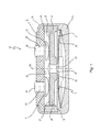
- Fig. 1 is denoted by a temperature-dependent switch 10, which includes a temperature-dependent switching mechanism 11 which is housed in a housing 12.
- the housing 12 comprises a lower part 14 and a closing this upper part 15 which is held by a flanged edge 16 of the lower part 14 at this. Between the lower part 14 and the upper part 15, a ring 17 is arranged, which is supported on a shoulder 18 of the lower part 14 and there leads a spring snap-action disc 21 of the rear derailleur 11 at its edge.
- the rear derailleur 11 additionally comprises, in addition to the spring snap-action disc 21, a bimetal snap-action disc 22 which, together with the spring snap disc 21, is centrally penetrated by a pin-like rivet 23 by which these are mechanically connected to a current transfer member in the form of a contact plate 24.
- the rivet 23 has a first shoulder 25 on which the bimetal snap disc 22 is seated with radial and axial play, with a second shoulder 26 is provided on which the spring snap disc 21 also sits with radial and axial play.
- the bimetallic snap disk 22 is supported with its peripheral edge inside in the lower part 14.
- the already mentioned contact plate 24 has in the direction of the upper part 15 two electrically interconnected, large-area contact surfaces 27 which cooperate with two arranged on the inside 29 of the upper part 29 stationary contacts 31, 32, the inner heads of contact rivets 33, 34 are the pass through the upper part 15 and with their outer heads 35, 36 serve the external connection.
- the bimetal snap-action disc 22 If the temperature of the bimetal snap-action disc 22 increases beyond its response temperature, it snaps from the convex into a concave shape and supports itself with its edge in the region of the ring 17 and pulls the contact plate 24 against the force of the spring. Snap-action disc 21 away from the stationary contacts 31, 32; the switch 10 is now open.
- the upper part 15 made of a PTC thermistor, so represents a PTC resistor, which is electrically connected between the stationary contacts 31, 32.
- the upper part 15 thus acts as a self-holding resistor, as has already been described in detail above.
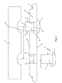
- FIG. 2 schematically shows how the upper part 15 is fitted with the contact rivets 33, 34, each having a setting head 37, 38 in the unformed state, from which a rivet shank 41, 42 extends, having a free end 43, 44 which with Help a schematically indicated at 45 molding tool is converted to closing heads.
- the inner diameter 48, 49 of the through holes 46, 47 and the outer diameter 51, 52 of the contact rivets 33, 34 are matched to each other with very tight tolerances, so that the position of the inner heads 37, 38 and the outer heads 35, 36 on the upper part 15th as accurately as possible.
- the diameters 48, 49, 51, 52 in Fig. 2 are therefore almost the same size.
- the upper part 15 is made of a PTC thermistor material and is solidified after pressing by sintering. In this sintering, the distance between the passage openings 46, 47 indicated at 54 changes slightly so that the two contact rivets 33, 34 can not be inserted into the passage openings 46, 47 simultaneously and fully automatically.
- the new switch 10 can be assembled.
- Fig. 3 the switch 10 is off Fig. 1 shown in an exploded view, the above according to Fig. 2 manufactured upper part 15 can be seen.
- the contact surfaces 27 on the contact plate 24 have such a large extent in the radial direction that the stationary contacts 31, 32 always get into secure contact with the contact surfaces 27, even if their distance to the center line 54 varies due to production.
Landscapes
- Engineering & Computer Science (AREA)
- Manufacturing & Machinery (AREA)
- Physics & Mathematics (AREA)
- Thermal Sciences (AREA)
- Thermally Actuated Switches (AREA)
Applications Claiming Priority (1)
| Application Number | Priority Date | Filing Date | Title |
|---|---|---|---|
| DE102011015116A DE102011015116A1 (de) | 2011-03-22 | 2011-03-22 | Verfahren zur Herstellung eines temperaturabhängigen Schalters |
Publications (1)
| Publication Number | Publication Date |
|---|---|
| EP2503576A1 true EP2503576A1 (fr) | 2012-09-26 |
Family
ID=45954305
Family Applications (1)
| Application Number | Title | Priority Date | Filing Date |
|---|---|---|---|
| EP12158572A Withdrawn EP2503576A1 (fr) | 2011-03-22 | 2012-03-08 | Procédé destiné à la fabrication d'un commutateur dépendant de la température |
Country Status (2)
| Country | Link |
|---|---|
| EP (1) | EP2503576A1 (fr) |
| DE (1) | DE102011015116A1 (fr) |
Cited By (1)
| Publication number | Priority date | Publication date | Assignee | Title |
|---|---|---|---|---|
| EP2874171A1 (fr) * | 2013-10-17 | 2015-05-20 | Thermik Gerätebau GmbH | Mécanisme de commutation variable avec la température |
Families Citing this family (2)
| Publication number | Priority date | Publication date | Assignee | Title |
|---|---|---|---|---|
| DE102023104830B3 (de) | 2023-02-28 | 2024-05-16 | Marcel P. HOFSAESS | Temperaturabhängiger Schalter |
| DE102023104839B3 (de) * | 2023-02-28 | 2024-05-16 | Marcel P. HOFSAESS | Temperaturabhängiger Schalter |
Citations (4)
| Publication number | Priority date | Publication date | Assignee | Title |
|---|---|---|---|---|
| DE2644411C2 (de) | 1976-10-01 | 1984-08-16 | Hofsäss, Peter, 7530 Pforzheim | Temperaturwächter |
| DE19609577A1 (de) * | 1996-03-12 | 1997-09-18 | Thermik Geraetebau Gmbh | Schalter mit einem temperaturabhängigen Schaltwerk |
| DE19517310C2 (de) | 1995-05-03 | 1999-12-23 | Thermik Geraetebau Gmbh | Baustein aus Kaltleitermaterial und Temperaturwächter mit einem solchen Baustein |
| DE19827113A1 (de) | 1998-06-18 | 1999-12-30 | Marcel Hofsaes | Temperaturabhängiger Schalter mit Stromübertragungsglied |
-
2011
- 2011-03-22 DE DE102011015116A patent/DE102011015116A1/de not_active Withdrawn
-
2012
- 2012-03-08 EP EP12158572A patent/EP2503576A1/fr not_active Withdrawn
Patent Citations (5)
| Publication number | Priority date | Publication date | Assignee | Title |
|---|---|---|---|---|
| DE2644411C2 (de) | 1976-10-01 | 1984-08-16 | Hofsäss, Peter, 7530 Pforzheim | Temperaturwächter |
| DE19517310C2 (de) | 1995-05-03 | 1999-12-23 | Thermik Geraetebau Gmbh | Baustein aus Kaltleitermaterial und Temperaturwächter mit einem solchen Baustein |
| DE19609577A1 (de) * | 1996-03-12 | 1997-09-18 | Thermik Geraetebau Gmbh | Schalter mit einem temperaturabhängigen Schaltwerk |
| DE19827113A1 (de) | 1998-06-18 | 1999-12-30 | Marcel Hofsaes | Temperaturabhängiger Schalter mit Stromübertragungsglied |
| DE19827113C2 (de) | 1998-06-18 | 2001-11-29 | Marcel Hofsaes | Temperaturabhängiger Schalter mit Stromübertragungsglied |
Cited By (2)
| Publication number | Priority date | Publication date | Assignee | Title |
|---|---|---|---|---|
| EP2874171A1 (fr) * | 2013-10-17 | 2015-05-20 | Thermik Gerätebau GmbH | Mécanisme de commutation variable avec la température |
| US10256061B2 (en) | 2013-10-17 | 2019-04-09 | Thermik Geraetebau Gmbh | Temperature-dependent switching mechanism |
Also Published As
| Publication number | Publication date |
|---|---|
| DE102011015116A1 (de) | 2012-09-27 |
Similar Documents
| Publication | Publication Date | Title |
|---|---|---|
| EP0966014B1 (fr) | Interrupteur à commande thermique avec élément de transfert de courant | |
| DE102008048554B3 (de) | Temperaturabhängiger Schalter | |
| DE102011101862B4 (de) | Temperaturabhängiger Schalter mit Stromübertragungsglied | |
| DE102011119632B3 (de) | Temperaturabhängiges Schaltwerk | |
| EP2846344B1 (fr) | Commutateur thermique | |
| DE102007014237A1 (de) | Temperaturabhängiger Schalter und dafür vorgesehenes Schaltwerk | |
| EP2747110B1 (fr) | Circuit de protection contre les hautes températures | |
| EP0920044A2 (fr) | Interrupteur avec un mécanisme de commutation sensible à la température | |
| DE102011119637B4 (de) | Temperaturabhängiger Schalter mit einem temperaturabhängigen Schaltwerk sowie Verfahren zum Herstellen eines solchen Schalters | |
| EP0951040B1 (fr) | Interrupteur à commande thermique | |
| EP2503581B1 (fr) | Commutateur thermodépendant avec circuit de transmission de courant | |
| DE102014108518A1 (de) | Temperaturabhängiger Schalter mit Distanzring | |
| DE19636640C2 (de) | Schalter mit einem Sicherheitselement | |
| EP0740323B1 (fr) | Thermostat avec un dispositif interrupteur à bimétal commutant en cas de surchauffe | |
| EP2503576A1 (fr) | Procédé destiné à la fabrication d'un commutateur dépendant de la température | |
| EP4411777A1 (fr) | Commutateur dépendant de la température | |
| EP2654057B1 (fr) | Commutateur thermodépendant | |
| EP2038905B1 (fr) | Capuchon de connexion et commutateur à capuchon de connexion | |
| EP2506281B1 (fr) | Commutateur thermodépendant avec résistance protectrice | |
| DE2511214C2 (de) | Temperaturregeleinrichtung für elektrische Geräte | |
| DE102011016133B4 (de) | Temperaturabhängiger Schalter mit Vorwiderstand | |
| DE102011104984B4 (de) | Temperaturabhängiger Schalter mit Heizwiderstand auf Trägerplatte | |
| DE102011122890A1 (de) | Temperaturabhängiges Schaltwerk | |
| EP4528772A2 (fr) | Mécanisme de commutation dépendant de la température et commutateur dépendant de la température | |
| DE102004014028A1 (de) | Schutz-Temperatur-Begrenzer mit integriertem Heizelement |
Legal Events
| Date | Code | Title | Description |
|---|---|---|---|
| PUAI | Public reference made under article 153(3) epc to a published international application that has entered the european phase |
Free format text: ORIGINAL CODE: 0009012 |
|
| AK | Designated contracting states |
Kind code of ref document: A1 Designated state(s): AL AT BE BG CH CY CZ DE DK EE ES FI FR GB GR HR HU IE IS IT LI LT LU LV MC MK MT NL NO PL PT RO RS SE SI SK SM TR |
|
| AX | Request for extension of the european patent |
Extension state: BA ME |
|
| 17P | Request for examination filed |
Effective date: 20130313 |
|
| 17Q | First examination report despatched |
Effective date: 20131203 |
|
| STAA | Information on the status of an ep patent application or granted ep patent |
Free format text: STATUS: THE APPLICATION HAS BEEN WITHDRAWN |
|
| 18W | Application withdrawn |
Effective date: 20140412 |