EP2503581B1 - Commutateur thermodépendant avec circuit de transmission de courant - Google Patents
Commutateur thermodépendant avec circuit de transmission de courant Download PDFInfo
- Publication number
- EP2503581B1 EP2503581B1 EP12159876.7A EP12159876A EP2503581B1 EP 2503581 B1 EP2503581 B1 EP 2503581B1 EP 12159876 A EP12159876 A EP 12159876A EP 2503581 B1 EP2503581 B1 EP 2503581B1
- Authority
- EP
- European Patent Office
- Prior art keywords
- snap
- edge
- switch according
- action disc
- stationary contacts
- Prior art date
- Legal status (The legal status is an assumption and is not a legal conclusion. Google has not performed a legal analysis and makes no representation as to the accuracy of the status listed.)
- Active
Links
Images
Classifications
-
- H—ELECTRICITY
- H01—ELECTRIC ELEMENTS
- H01H—ELECTRIC SWITCHES; RELAYS; SELECTORS; EMERGENCY PROTECTIVE DEVICES
- H01H37/00—Thermally-actuated switches
- H01H37/02—Details
- H01H37/32—Thermally-sensitive members
- H01H37/52—Thermally-sensitive members actuated due to deflection of bimetallic element
- H01H37/54—Thermally-sensitive members actuated due to deflection of bimetallic element wherein the bimetallic element is inherently snap acting
- H01H37/5427—Thermally-sensitive members actuated due to deflection of bimetallic element wherein the bimetallic element is inherently snap acting encapsulated in sealed miniaturised housing
Definitions
- the present invention relates to a temperature-dependent switch with a temperature-dependent switching mechanism with a round snap-action disc, a housing receiving the switching mechanism, which has a lower part and a top, two provided on the upper part on the inside stationary contacts, each of which is connected to an associated external connection is, as well as arranged on the snap disk and moved by this current transmission member, wherein the snap disc is supported with its edge on a support surface in the switch to press the current transfer member temperature-dependent with the two stationary contacts in plant and / or stand out from them.
- Such a switch is from the DE 26 44 411 C2 known.
- the known switch has a housing with a cup-shaped lower part, in which a temperature-dependent switching mechanism is inserted.
- the lower part is closed by an upper part, which is held by the raised edge of the lower part of this.
- the lower part can be made of metal or insulating material, while the upper part here in any case consists of insulating material.
- the rear derailleur carries a current transfer member in the form of a contact bridge, on top of which a silver support is provided which has two interconnected mating contacts, which are brought into contact with the two stationary contacts depending on the temperature and then electrically connect them together.
- the outer heads of the two rivets serve as external connections.
- the temperature-dependent switching mechanism has a circular in plan view bimetallic snap disk and a circular in plan view spring snap-action disc, which are centrally penetrated by a pin which carries the contact bridge.
- the spring snap-action disc is circumferentially guided in the housing, while the bimetallic snap disk is supported depending on the temperature at a support surface formed by the shoulder of the lower part or the edge of the spring snap disk and thereby allows either the contact bridge to abut the two stationary contacts or the contact bridge lifts off from the stationary contacts, so that the electrical connection between the external connections is interrupted.
- This temperature-dependent switch is used in a known manner to protect electrical equipment from overheating. This will be the switch electrically connected in series with the device to be protected and mechanically arranged on the device so that it is in thermal communication with this.
- the contact bridge is applied to the two stationary contacts, so that the circuit is closed and the device to be protected is supplied with power via the switch. If the temperature rises above a permissible value, the bimetallic snap-action disc lifts the contact bridge away from the stationary contacts, thus opening the switch and interrupting the supply of the device to be protected.
- the now de-energized device can then cool down again.
- the thermally coupled to the device switch cools down again, which then automatically closes again.
- the contact bridge of the known switch By dimensioning the contact bridge of the known switch is able, compared to other temperature-dependent switches in which the operating current of the device to be protected flows directly through the bimetallic snap disk or its associated spring snap-action, so much higher operating currents to lead that it can be used to protect larger electrical appliances with high power consumption.
- the known switch automatically switches on again after cooling the device protected by it. While such a switching behavior for protecting a hair dryer, for example, can be quite useful, this is not desirable anywhere where the device to be protected after switching off may not automatically turn on again to avoid damage. This applies, for example, for electric motors that are used as drive units.
- the DE 198 27 113 proposes therefore to provide a so-called self-holding resistor, which is electrically parallel to the external terminals.
- the self-holding resistor is in the open switch electrically in series with the device to be protected, through which only a harmless residual current now flows because of the resistance value of the self-holding resistor.
- this residual current is sufficient to heat the self-holding resistor so far that it emits a heat that holds the bimetallic snap disk above its switching temperature.
- the from the DE 198 27 113 Known switch may also be equipped with a current-dependent switching function, to which a further resistor is provided, which is permanently connected in series with the external terminals.
- the operating current of the device to be protected thus flows constantly through this heating resistor, which can be dimensioned so that it ensures that when exceeding a certain operating current that the bimetallic snap disk is heated to a temperature above its response temperature, so that the switch at an increased Operating current already opens before the device to be protected has warmed up inadmissible.
- this object is achieved in the switch mentioned above in that at the edge of the snap-action disc and / or on the Support surface for the edge at least one unevenness is provided, such that the snap disc rotates at each switching about its vertical axis.
- the "unevenness” is thus provided in the context of the present invention either on the edge of the snap disk itself and alternatively or additionally also on a support surface for the edge.
- This support surface may be a shoulder on which the snap disk is supported when opening and / or closing the switch.
- a "unevenness” is understood to mean a deviation of the end face of the edge and / or the relevant contact surface from the uniformity in the form of a plane plane planned so far in the prior art, which means that the edge is no longer in the circumferential direction evenly rests on a shoulder or annular surface in the lower part, since the support contact is curved so to speak, so that, for example, an inclined, ascending or descending support surface is formed on or for the edge of the snap disk.
- the unevenness may be a projection or a depression in the edge of the snap-action disk or on a bearing surface for the edge.
- the unevenness may extend over a circumferential range of more than 180 ° to nearly 360 °. Then it is a screw-like edge or a helical bearing surface for the edge, so that sets a twisting effect for the snap disc, which also always runs in the same direction.
- bumps can each extend in the circumferential direction by 45 ° to 90 °.
- the inventor of the present application has recognized that such unevenness causes the snap-action disc and thus also the current-transmitting member to rotate with each switching operation, namely slightly, ie only by a few degrees.
- This slight rotation when opening and / or closing the switch causes not always exactly the same place on the power transmission member comes into contact with the mating contacts when the new switch closes after an opening operation again.
- the contact surface available on the current transfer element is better utilized, so that the proportion of the contact resistance caused by the current transfer element is distributed over many different contact points, and it takes a correspondingly longer time until the contact resistance as a whole reaches an impermissible value.
- the effect of the rotating snap disk primarily results in that the proportion of the contact resistance on the current transmission member increases more slowly. This does not apply to the same extent to the contribution of the stationary contacts to the contact resistance.
- the rotation of the current transmitting member also causes the proportion of the contact resistance attributable to the stationary contacts to increase more slowly with the switching operations than in the prior art.
- the snap-action discs themselves do not have to be changed constructively so that available snap-action discs can be used in order to achieve the turning effect according to the invention.
- the thermal and mechanical properties of the snap discs do not need to be redesigned.
- unevennesses are provided on the snap-action disc, they can interact with the unevennesses on the support surface in such a way that the snap-action disc rotates slightly each time it is switched.
- These bumps can interact like gears, as they are found, for example, in ball press, where they cause a rotation of the switching mechanism with each pressing movement to extend the write mine at the first press and retract the second press.
- the snap-action disc can be a bimetallic snap-action disc which ensures the closing pressure and the temperature-dependent opening movement.
- the closing pressure can also be applied alone or in addition by a Federschnappulation, while a bimetallic snap disk is provided, which either provides only for the opening movement or contributes to the contact pressure in its low temperature position.
- edge of bimetal or spring snap-action disc or the edges of both snap discs are provided according to the invention with at least one unevenness.
- unevenness may be provided on support surfaces in the sense described above.
- the bimetallic snap disk comes namely with its edge into contact with a support surface in the Switch, which leads due to the unevenness to a rotation of the bimetallic snap disk relative to the housing. It does not matter whether the bimetallic snap disk also contributes to the contact pressure in the closed position of the switch, or whether this is effected solely by the Federschnappulation.
- the snap-action disc is a bimetallic snap-action disc which is mechanically connected to the current-transmitting member and presses it below its switching temperature against the stationary contacts and lifts them above their switching temperature.
- the snap-action disc is a spring snap-action disc which biases the current transfer member in the manner of abutment with the stationary contacts, and further comprises a bimetal snap-action disc which lifts the current transfer member above its switching temperature from the stationary contacts, further Preferably, the spring snap-action disc between the current transfer member and bimetallic snap disk is arranged.
- the current transmission member is an approximately round contact plate, which is provided on its surface facing the stationary contacts with a circumferentially closed contact surface.
- the contact plate is preferably connected by a pin-like rivet centric with the bimetallic snap disk and possibly the spring snap-action disc.
- the contact plate can turn particularly easily when it is connected via a rivet centric with the snap discs.
- the upper part is penetrated by two rivets whose inner heads serve as stationary contacts and their outer heads as external connections.
- each terminal electrode is encapsulated with the upper part, each of which is connected to one of the stationary contacts and one of the outer terminals, wherein preferably each terminal electrode is a flat metal part with which the respective outer terminal, preferably laterally from the upper part protrudes, is integrally formed, more preferably, the terminal electrodes are parallel to each other in the upper part.
- a particular advantage lies in the production of the new switch, because the terminal electrodes can be connected in a first step with stationary contacts and the external terminals, whereupon at Spraying of the upper part of the terminal electrodes are cast or molded so to speak.
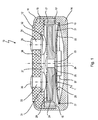
- Fig. 1 is denoted by a temperature-dependent switch 10, which includes a temperature-dependent switching mechanism 11 which is housed in a housing 12.
- the housing 12 comprises a lower part 14 and a closing this upper part 15 which is held by a flanged edge 16 of the lower part 14 at this. Between the lower part 14 and the upper part 15, a ring 17 is arranged, which is supported on a shoulder 18 of the lower part 14 and there leads a spring snap-action disc 21 of the rear derailleur 11 at its edge 19.
- the rear derailleur 11 additionally comprises, in addition to the spring snap-action disc 21, a bimetal snap-action disc 22 which, together with the spring snap disc 21, is centrally penetrated by a pin-like rivet 23 by which these are mechanically connected to a current transfer member in the form of a contact plate 24.
- the rivet 23 has a first shoulder 25 on which the bimetal snap disc 22 is seated with radial and axial play, with a second shoulder 26 is provided on which the spring snap disc 21 also sits with radial and axial play.
- the bimetal snap-action disc 22 is supported with its peripheral edge 27 on a shoulder 28 running inside in the lower part 14, which forms an annular bearing surface for the edge 27.
- the already mentioned contact plate 24 has in the direction of the upper part 15 a radially encircling contact surface 29 which cooperates with stationary contacts 31, 32 which are inner heads of rivets 33, 34 which pass through the upper part 15 and with their outer heads external connections 35, 36 form.
- the bimetal snap-action disc 22 If the temperature of the bimetal snap-action disc 22 increases beyond its response temperature, it snaps from the convex into a concave shape and supports itself with its edge 27 in the region of the ring 17 and pulls the contact plate 24 against the force of the spring Snapping disk 21 away from the stationary contacts 31, 32; the switch 10 is now open.
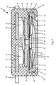
- a temperature-dependent switch 40 has a housing 41, in which the switching mechanism 11 from Fig. 1 is installed.
- the housing 41 here comprises a plate-like lower part 42, on the raised edge 43, an outer, circumferential groove 44 is provided.
- a cup-like upper part 45 is supported with an inner shoulder 46.
- an edge 47 On the shoulder 46 projects an edge 47, on which an inner circumferential bead 48 is provided, which is in engagement with the groove 44, whereby the lower part 42 is locked to the upper part 45.
- the edge 47 merges into an annular overlap 49, through which the lower part 42 is further held on the upper part 45.
- This overlap 49 can be generated by embossing or welding a protruding portion of the rim 47.
- the lower part 42 may also be made of insulating material or of metal, with a lower part made of metal results in a better thermal connection of the switch 40 to a device to be protected.
- connection electrodes 51, 52 are cast, each carrying a welded stationary contact 53, 54.
- the two stationary contacts 53, 54 are arranged on an inner side 55 of the upper part 45.
- the two terminal electrodes 51, 52 are formed as flat metal parts and formed integrally with external terminals 56, 57, which protrude laterally from the upper part 45.
- the two stationary contacts 53, 54 are temperature-dependent connected by the contact plate 24 with each other as in connection with Fig. 1 already described.
- the bimetallic disc 22 is also supported here with its edge 27 in the switching position shown on the shoulder 28 of the lower part 42. Furthermore, it can be seen better than in FIG. 12 that the spring snap-action disc 21 is peripherally guided with its edge 19 in a circumferential groove 59 which is formed between the shoulder 46 and the edge 43.
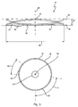
- Fig. 3 is shown in a sectional, schematic side view of the bimetallic snap disk 22, as in the deraille 11 from the Fig. 1 and 2 is used.
- the bimetallic snap disk 22 is in a conventional manner, a slightly dome-shaped, circular in plan view disc, the edge 27 usually has a completely flat, annular end face.
- the bimetallic snap disk 22 has, for example, a diameter 60 of about 8 mm, wherein its indicated at 61 height between the edge 27 and its dome-shaped elevation 62 is about 0.8 mm.
- the bimetallic snap disk 22 In its low-temperature position, the bimetallic snap disk 22 is supported on the shoulder 28, while it is supported in its high temperature position on a support surface 66 which may correspond to the edge 19 of the spring snap-action disc 21. If no spring snap disc 21 is provided, the bimetallic snap disk 22 is supported with its edge 27 accordingly on a shoulder 67 forming the bearing surface, which in the switch according to Fig. 1 downward pointing to the ring 17 and the switch according to Fig. 2 is provided in the groove 59.
- the bumps 63 and 64 now cause the bimetallic snap disk 22 to rotate about its vertical axis 65 when alternately supported on the shoulder 28 and the support surface 66.
- the bimetallic snap disk 22 has at least one such unevenness 63, 64.
- the unevenness 63 is formed in the example shown by an over the otherwise plane ring plane 68 of the rim 27 excellent protrusion of 0.2 mm and the unevenness 64 by a corresponding recess of 0.2 mm.
- the unevenness 63 extends for example over a circumferential angle range 69 of 50 ° and the unevenness 64 over a circumferential angle range 71 of 80 °, as shown in FIG Fig. 3 is shown below, where the bimetallic snap disk 22 is shown in bottom view.
- edge 27 is not flat but so "crooked” that it does not rest evenly and evenly on the shoulder 27 and the support surface 66.
- the spring-snap-action disc 21, which is also round in plan view and is preferably circular, may be formed at its edge 19 with corresponding unevennesses 63, 64.
- the bimetallic snap disk 22 is provided at its edge 27 with at least one unevenness 63, 64, even if the bimetallic snap disk 22 in its in Fig. 1 shown low temperature position is not supported with its edge 27 on the shoulder 28, but is free of forces.
- you open the switch it gets namely, with its edge 27 in contact with the here forming the bearing surface shoulder 19 of the spring snap disk 21, which leads to a rotation of the bimetallic snap disk 22 relative to the housing 12 because of the unevenness 63, 64.
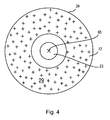
- Fig. 4 is still a plan view of the contact plate 24 from the rear deraille 11 in the Fig. 1 and 2 shown.
- the contact plate 24 is rotationally symmetrical to the Fig. 3 shown vertical axis 65 of the bimetallic snap disk 22 is formed.
- the contact surface 29 which is circumferentially closed in itself and thus formed as an annular surface.
- the surface 72 is formed on its entire annular surface by suitable coating or treatment as an electrically conductive contact area, the two stationary contacts 31 and 32 of Fig. 1 or 53 and 54 off Fig. 2 electrically interconnects when in contact with the contact surface.
- Fig. 5 is in a further embodiment example very schematically and in detail a development of the bimetallic snap disk 22 and the shoulder 28 of the lower part 14 shown over 360 °.
- the edge 27 of the bimetallic snap disk 22 is flat, while the shoulder 28 is provided with a projecting over its ring plane 73 unevenness 74 having a gradually increasing in the circumferential direction bearing surface 75.
- the unevenness 74 extends over a circumferential region 81 of 340 °, that is to say of nearly 360 °.
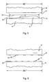
- Fig. 6 is in a presentation like Figure 5 in a further embodiment shown that both the edge 27 of the bimetallic snap disk 22 and the shoulder 28 with many, circumferentially distributed unevennesses 76, 77 is provided.
- the number of bumps 76 may correspond to the number of bumps 77, but this is not necessary and in many cases not desirable.
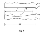
- the unevenness may alternatively-like the unevenness 64-also be formed as a recessed unevenness 78, which has a contact surface 79 gradually sloping below the ring plane 73 in the circumferential direction.
- This embodiment is in Fig. 7 shown.
- the unevenness extends over a circumferential region 81 of 340 °, ie a circumferential angle range of almost 360 °.
- the peripheral region 81 can also be selected smaller than 340 °, for example 180 ° or 270 °.
- the bumps 74, 78 may just as well be formed on the edge 27 of the bimetallic snap disk 22, the shoulder 28 then having a completely plane ring plane 73.
Landscapes
- Physics & Mathematics (AREA)
- Thermal Sciences (AREA)
- Thermally Actuated Switches (AREA)
Claims (15)
- Commutateur thermodépendant comprenant un mécanisme de commutation (11) thermodépendant doté d'un disque d'arrêt (21, 22) rond, un boîtier (12 ; 41) logeant le mécanisme de commutation (11), qui présente une partie inférieure (14 ; 42) ainsi qu'une partie supérieure (15 ; 45), deux contacts stationnaires (31, 32 ; 53, 54) prévus au niveau de la partie supérieure (15 ; 45), au niveau du côté intérieur (37 ; 55) de cette dernière, chacun desdits contacts étant raccordé à un système de connexion extérieur (35, 36 ; 56, 57) qui lui est associé, ainsi qu'un organe de transmission de courant (24) disposé au niveau du disque d'arrêt (21, 22) et déplacé par ce dernier, sachant que le disque d'arrêt (21, 22) s'appuie par son bord (27, 19) sur une face d'appui (28, 66, 67, 73) dans le commutateur (10, 40) afin d'amener en appui par pression l'organe de transmission de courant (24) avec les deux contacts stationnaires (31, 32 ; 53, 54) selon la température et/ou afin de relever ledit organe de transmission de courant pour l'éloigner de ces derniers,
caractérisé en ce qu'au moins une irrégularité (63, 64, 74, 76, 77, 78) est prévue au niveau du bord (19, 27) du disque d'arrêt (21, 22) et/ou au niveau de la face d'appui (28, 66, 67, 73) pour le bord (19, 27) de telle manière que le disque d'arrêt (21, 22) tourne autour de son axe supérieur (65) à chaque opération de commutation. - Commutateur selon la revendication 1, caractérisé en ce que le disque d'arrêt (21, 22) est un disque d'arrêt bimétallique (22), qui est relié de manière mécanique à l'organe de transmission de courant (24) et qui presse ce dernier contre les contacts stationnaires (31, 32 ; 53, 54) en dessous de sa température de commutation et le relève de manière à l'éloigner de ces derniers au-dessus de sa température de commutation.
- Commutateur selon la revendication 1 ou 2, caractérisé en ce que le disque d'arrêt (21, 22) est un disque d'arrêt (21) à ressorts, qui précontraint l'organe de transmission de courant (24) au sens d'un appui au niveau des contacts stationnaires (31, 32 ; 53, 54), et en ce qu'en outre est prévu un disque d'arrêt bimétallique (22) qui relève l'organe de transmission de courant (24) de manière à l'éloigner des contacts stationnaires (31, 32 ; 53, 54) au-dessus de sa température de commutation.
- Commutateur selon la revendication 3, caractérisé en ce que le disque d'arrêt à ressorts (21) est disposé entre l'organe de transmission de courant (24) et le disque d'arrêt bimétallique (22).
- Commutateur selon l'une quelconque des revendications 1 à 4, caractérisé en ce que l'organe de transmission de courant est une plaque de contact (24) à peu près ronde, qui est pourvue, sur sa surface (72) tournée vers les contacts stationnaires (31, 32 ; 53, 54), d'une face de contact (29) fermée dans la direction périphérique.
- Commutateur selon l'une quelconque des revendications 1 à 5, caractérisé en ce que la partie supérieure (15) est traversée par deux rivets (33, 34), dont les têtes situées à l'intérieur font office de contacts stationnaires (31, 32) et dont les têtes situées à l'extérieur font office de systèmes de connexion extérieurs (35, 36).
- Commutateur selon l'une quelconque des revendications 1 à 5, caractérisé en ce que deux électrodes de connexion (51, 52) sont scellées à la partie supérieure (45), chaque électrode de connexion étant raccordée à un des contacts stationnaires (53, 54) et à un des systèmes de connexion extérieurs (56, 57).
- Commutateur selon la revendication 7, caractérisé en ce que chaque électrode de connexion (51, 52) est une pièce métallique plate, avec laquelle le système de connexion extérieur (56, 57) respectif, qui dépasse de préférence latéralement de la partie supérieure (45), est réalisé d'un seul tenant.
- Commutateur selon l'une quelconque des revendications 1 à 8, caractérisé en ce que l'irrégularité (63, 64, 74, 76, 77, 78) comprend une partie faisant saillie (63) réalisée au niveau du bord (19, 27) du disque d'arrêt (21, 22), laquelle partie faisant saillie fait saillie du plan annulaire (68) plan du bord (19,27).
- Commutateur selon l'une quelconque des revendications 1 à 8, caractérisé en ce que l'irrégularité (63, 64, 74, 76, 77, 78) comprend un renfoncement (64) réalisé au niveau du bord (19, 27) du disque d'arrêt (21, 22), lequel renfoncement est en retrait par rapport au plan annulaire (68) plan du bord (27).
- Commutateur selon l'une quelconque des revendications 1 à 10, caractérisé en ce que l'irrégularité (63, 64, 74, 76, 77, 78) comprend une partie faisant saillie (74) réalisée au niveau de la face d'appui (28, 66, 67, 73) pour le bord (19, 27) du disque d'arrêt (21, 22), laquelle partie faisant saillie fait saillie au-delà du plan annulaire (73) de la face d'appui (28, 66, 67, 73).
- Commutateur selon l'une quelconque des revendications 1 à 11, caractérisé en ce que l'irrégularité (63, 64, 74, 76, 77, 78) comprend un renfoncement (78) réalisé au niveau de la face d'appui (28, 66, 67, 73) pour le bord (19, 27) du disque métallique (21, 22), lequel renfoncement est en retrait par rapport au plan annulaire (73) de la face d'appui (28, 66).
- Commutateur selon l'une quelconque des revendications 1 à 12, caractérisé en ce que l'irrégularité (63, 64) s'étend sur une plage angulaire (69, 71) périphérique allant de 45° à 90°.
- Commutateur selon l'une quelconque des revendications 1 à 12, caractérisé en ce que l'irrégularité (74, 78) s'étend sur une plage périphérique (81) supérieure à 180°.
- Commutateur selon la revendication 13, caractérisé en ce que l'irrégularité (74, 78) comprend une face d'appui (75, 79) ascendante ou descendante sur la périphérie.
Applications Claiming Priority (1)
| Application Number | Priority Date | Filing Date | Title |
|---|---|---|---|
| DE102011016142A DE102011016142A1 (de) | 2011-03-25 | 2011-03-25 | Temperaturabhängiger Schalter mit Stromübertragungsglied |
Publications (2)
| Publication Number | Publication Date |
|---|---|
| EP2503581A1 EP2503581A1 (fr) | 2012-09-26 |
| EP2503581B1 true EP2503581B1 (fr) | 2014-06-04 |
Family
ID=45954330
Family Applications (1)
| Application Number | Title | Priority Date | Filing Date |
|---|---|---|---|
| EP12159876.7A Active EP2503581B1 (fr) | 2011-03-25 | 2012-03-16 | Commutateur thermodépendant avec circuit de transmission de courant |
Country Status (3)
| Country | Link |
|---|---|
| EP (1) | EP2503581B1 (fr) |
| CN (1) | CN102693869B (fr) |
| DE (1) | DE102011016142A1 (fr) |
Families Citing this family (7)
| Publication number | Priority date | Publication date | Assignee | Title |
|---|---|---|---|---|
| DE102012112487A1 (de) | 2012-12-18 | 2014-06-18 | Thermik Gerätebau GmbH | Temperaturschutzschaltung |
| DE102013101392A1 (de) | 2013-02-13 | 2014-08-14 | Thermik Gerätebau GmbH | Temperaturabhängiger Schalter |
| DE102013017232A1 (de) * | 2013-10-17 | 2015-04-23 | Thermik Gerätebau GmbH | Temperaturabhängiges Schaltwerk |
| CN104037018A (zh) * | 2014-06-12 | 2014-09-10 | 扬州宝珠电器有限公司 | 触点开距增幅性温度传感器 |
| CN104134579A (zh) * | 2014-07-28 | 2014-11-05 | 常州常胜精密电子有限公司 | 多开关温度保护器 |
| DE102018100890B3 (de) | 2018-01-16 | 2019-07-18 | Marcel P. HOFSAESS | Temperaturabhängiger Schalter |
| DE102019112074B4 (de) | 2019-05-09 | 2020-12-17 | Marcel P. HOFSAESS | Temperaturabhängiger Schalter |
Family Cites Families (14)
| Publication number | Priority date | Publication date | Assignee | Title |
|---|---|---|---|---|
| US2289131A (en) * | 1939-11-04 | 1942-07-07 | Westinghouse Electric & Mfg Co | Snap-acting link |
| US2720416A (en) * | 1951-10-16 | 1955-10-11 | Underwood Electric & Mfg Co In | Snap acting thermostatic elements and methods of making the same |
| DE1162915B (de) * | 1960-03-10 | 1964-02-13 | Otto Mueller | Einseitig eingespannter, am freien Ende Kontakte tragender umschnappbarer Bimetallstreifen |
| US3143614A (en) * | 1961-04-07 | 1964-08-04 | Underwriters Safety Device Co | Bi-metallic circuit breaker snap reed |
| DE7630734U1 (de) | 1976-10-01 | 1977-01-20 | Hofsaess, Peter, 7530 Pforzheim | Temperaturwächter |
| DE9406806U1 (de) * | 1994-04-23 | 1995-06-01 | Thermik Gerätebau GmbH, 75181 Pforzheim | Bimetallschalter, insbesondere stromabhängiger Schalter |
| DE19708436C2 (de) | 1997-03-01 | 1999-08-19 | Hofsaes | Temperaturabhängiger Schalter mit Kontaktbrücke und Verfahren zu dessen Herstellung |
| DE19727197C2 (de) | 1997-06-26 | 1999-10-21 | Marcel Hofsaess | Temperaturabhängiger Schalter mit Kontaktbrücke |
| JP4279367B2 (ja) * | 1997-10-08 | 2009-06-17 | 株式会社生方製作所 | 感熱スイッチ |
| DE19827113C2 (de) | 1998-06-18 | 2001-11-29 | Marcel Hofsaes | Temperaturabhängiger Schalter mit Stromübertragungsglied |
| GB2349508B (en) * | 1999-04-26 | 2003-04-16 | Otter Controls Ltd | Improvements relating to thermally-responsive controls |
| CN101162664A (zh) * | 2007-10-19 | 2008-04-16 | 常州市恒立继电器厂 | 微型温控器 |
| CN101197225B (zh) * | 2007-12-03 | 2010-06-09 | 东莞大朗金准电器厂 | 温度调节开关 |
| CN101334675A (zh) * | 2008-07-25 | 2008-12-31 | 朱英年 | 一种突跳式温控器 |
-
2011
- 2011-03-25 DE DE102011016142A patent/DE102011016142A1/de not_active Withdrawn
-
2012
- 2012-03-16 EP EP12159876.7A patent/EP2503581B1/fr active Active
- 2012-03-22 CN CN201210078598.7A patent/CN102693869B/zh not_active Expired - Fee Related
Also Published As
| Publication number | Publication date |
|---|---|
| EP2503581A1 (fr) | 2012-09-26 |
| DE102011016142A1 (de) | 2012-09-27 |
| CN102693869B (zh) | 2017-04-12 |
| CN102693869A (zh) | 2012-09-26 |
Similar Documents
| Publication | Publication Date | Title |
|---|---|---|
| EP2503581B1 (fr) | Commutateur thermodépendant avec circuit de transmission de courant | |
| DE102008048554B3 (de) | Temperaturabhängiger Schalter | |
| EP2874171B1 (fr) | Mécanisme de commutation variable avec la température | |
| EP2854149B1 (fr) | Commutateur thermosensible doté d'un disque à action rapide disposé sur le bord | |
| EP3511968B1 (fr) | Commutateur dépendant de la température | |
| DE102011101862B4 (de) | Temperaturabhängiger Schalter mit Stromübertragungsglied | |
| DE102013101393B4 (de) | Temperaturabhängiger Schalter | |
| DE102011119632B3 (de) | Temperaturabhängiges Schaltwerk | |
| EP2958125B1 (fr) | Commutateur thermodépendant doté de bague d'espacement | |
| DE7229393U (de) | Temperaturschutzschalter | |
| EP0966014A1 (fr) | Interrupteur à commande thermique avec élément de transfert de courant | |
| DE2917482A1 (de) | Waermeschutzschalter | |
| DE3122899A1 (de) | Temperaturschalter | |
| EP0920044B1 (fr) | Interrupteur avec un mécanisme de commutation sensible à la température | |
| DE102007014237A1 (de) | Temperaturabhängiger Schalter und dafür vorgesehenes Schaltwerk | |
| DE102011119637B4 (de) | Temperaturabhängiger Schalter mit einem temperaturabhängigen Schaltwerk sowie Verfahren zum Herstellen eines solchen Schalters | |
| DE19527254A1 (de) | Temperaturwächter | |
| DE19609310A1 (de) | Schalter mit einem temperaturabhängigen Schaltwerk | |
| DE102019128367B4 (de) | Temperaturabhängiger schalter | |
| EP3736845B1 (fr) | Commutateur dépendant de la température | |
| EP2654057B1 (fr) | Commutateur thermodépendant | |
| EP3229255B1 (fr) | Commutateur thermique | |
| DE102011015116A1 (de) | Verfahren zur Herstellung eines temperaturabhängigen Schalters | |
| EP3270401B1 (fr) | Commutateur thermique doté de vitre isolante | |
| DE102023102304B4 (de) | Temperaturabhängiges Schaltwerk und temperaturabhängiger Schalter |
Legal Events
| Date | Code | Title | Description |
|---|---|---|---|
| PUAI | Public reference made under article 153(3) epc to a published international application that has entered the european phase |
Free format text: ORIGINAL CODE: 0009012 |
|
| AK | Designated contracting states |
Kind code of ref document: A1 Designated state(s): AL AT BE BG CH CY CZ DE DK EE ES FI FR GB GR HR HU IE IS IT LI LT LU LV MC MK MT NL NO PL PT RO RS SE SI SK SM TR |
|
| AX | Request for extension of the european patent |
Extension state: BA ME |
|
| REG | Reference to a national code |
Ref country code: HK Ref legal event code: DE Ref document number: 1170333 Country of ref document: HK |
|
| 17P | Request for examination filed |
Effective date: 20130308 |
|
| GRAP | Despatch of communication of intention to grant a patent |
Free format text: ORIGINAL CODE: EPIDOSNIGR1 |
|
| INTG | Intention to grant announced |
Effective date: 20131209 |
|
| GRAS | Grant fee paid |
Free format text: ORIGINAL CODE: EPIDOSNIGR3 |
|
| GRAA | (expected) grant |
Free format text: ORIGINAL CODE: 0009210 |
|
| AK | Designated contracting states |
Kind code of ref document: B1 Designated state(s): AL AT BE BG CH CY CZ DE DK EE ES FI FR GB GR HR HU IE IS IT LI LT LU LV MC MK MT NL NO PL PT RO RS SE SI SK SM TR |
|
| REG | Reference to a national code |
Ref country code: GB Ref legal event code: FG4D Free format text: NOT ENGLISH |
|
| REG | Reference to a national code |
Ref country code: CH Ref legal event code: EP |
|
| REG | Reference to a national code |
Ref country code: AT Ref legal event code: REF Ref document number: 671487 Country of ref document: AT Kind code of ref document: T Effective date: 20140615 |
|
| REG | Reference to a national code |
Ref country code: IE Ref legal event code: FG4D Free format text: LANGUAGE OF EP DOCUMENT: GERMAN |
|
| REG | Reference to a national code |
Ref country code: DE Ref legal event code: R096 Ref document number: 502012000803 Country of ref document: DE Effective date: 20140717 |
|
| REG | Reference to a national code |
Ref country code: NL Ref legal event code: VDEP Effective date: 20140604 |
|
| PG25 | Lapsed in a contracting state [announced via postgrant information from national office to epo] |
Ref country code: NO Free format text: LAPSE BECAUSE OF FAILURE TO SUBMIT A TRANSLATION OF THE DESCRIPTION OR TO PAY THE FEE WITHIN THE PRESCRIBED TIME-LIMIT Effective date: 20140904 Ref country code: FI Free format text: LAPSE BECAUSE OF FAILURE TO SUBMIT A TRANSLATION OF THE DESCRIPTION OR TO PAY THE FEE WITHIN THE PRESCRIBED TIME-LIMIT Effective date: 20140604 Ref country code: GR Free format text: LAPSE BECAUSE OF FAILURE TO SUBMIT A TRANSLATION OF THE DESCRIPTION OR TO PAY THE FEE WITHIN THE PRESCRIBED TIME-LIMIT Effective date: 20140905 Ref country code: CY Free format text: LAPSE BECAUSE OF FAILURE TO SUBMIT A TRANSLATION OF THE DESCRIPTION OR TO PAY THE FEE WITHIN THE PRESCRIBED TIME-LIMIT Effective date: 20140604 Ref country code: LT Free format text: LAPSE BECAUSE OF FAILURE TO SUBMIT A TRANSLATION OF THE DESCRIPTION OR TO PAY THE FEE WITHIN THE PRESCRIBED TIME-LIMIT Effective date: 20140604 |
|
| REG | Reference to a national code |
Ref country code: LT Ref legal event code: MG4D |
|
| PG25 | Lapsed in a contracting state [announced via postgrant information from national office to epo] |
Ref country code: RS Free format text: LAPSE BECAUSE OF FAILURE TO SUBMIT A TRANSLATION OF THE DESCRIPTION OR TO PAY THE FEE WITHIN THE PRESCRIBED TIME-LIMIT Effective date: 20140604 Ref country code: LV Free format text: LAPSE BECAUSE OF FAILURE TO SUBMIT A TRANSLATION OF THE DESCRIPTION OR TO PAY THE FEE WITHIN THE PRESCRIBED TIME-LIMIT Effective date: 20140604 Ref country code: SE Free format text: LAPSE BECAUSE OF FAILURE TO SUBMIT A TRANSLATION OF THE DESCRIPTION OR TO PAY THE FEE WITHIN THE PRESCRIBED TIME-LIMIT Effective date: 20140604 Ref country code: HR Free format text: LAPSE BECAUSE OF FAILURE TO SUBMIT A TRANSLATION OF THE DESCRIPTION OR TO PAY THE FEE WITHIN THE PRESCRIBED TIME-LIMIT Effective date: 20140604 |
|
| PG25 | Lapsed in a contracting state [announced via postgrant information from national office to epo] |
Ref country code: CZ Free format text: LAPSE BECAUSE OF FAILURE TO SUBMIT A TRANSLATION OF THE DESCRIPTION OR TO PAY THE FEE WITHIN THE PRESCRIBED TIME-LIMIT Effective date: 20140604 Ref country code: RO Free format text: LAPSE BECAUSE OF FAILURE TO SUBMIT A TRANSLATION OF THE DESCRIPTION OR TO PAY THE FEE WITHIN THE PRESCRIBED TIME-LIMIT Effective date: 20140604 Ref country code: ES Free format text: LAPSE BECAUSE OF FAILURE TO SUBMIT A TRANSLATION OF THE DESCRIPTION OR TO PAY THE FEE WITHIN THE PRESCRIBED TIME-LIMIT Effective date: 20140604 Ref country code: EE Free format text: LAPSE BECAUSE OF FAILURE TO SUBMIT A TRANSLATION OF THE DESCRIPTION OR TO PAY THE FEE WITHIN THE PRESCRIBED TIME-LIMIT Effective date: 20140604 Ref country code: PT Free format text: LAPSE BECAUSE OF FAILURE TO SUBMIT A TRANSLATION OF THE DESCRIPTION OR TO PAY THE FEE WITHIN THE PRESCRIBED TIME-LIMIT Effective date: 20141006 Ref country code: SK Free format text: LAPSE BECAUSE OF FAILURE TO SUBMIT A TRANSLATION OF THE DESCRIPTION OR TO PAY THE FEE WITHIN THE PRESCRIBED TIME-LIMIT Effective date: 20140604 |
|
| PG25 | Lapsed in a contracting state [announced via postgrant information from national office to epo] |
Ref country code: NL Free format text: LAPSE BECAUSE OF FAILURE TO SUBMIT A TRANSLATION OF THE DESCRIPTION OR TO PAY THE FEE WITHIN THE PRESCRIBED TIME-LIMIT Effective date: 20140604 Ref country code: IS Free format text: LAPSE BECAUSE OF FAILURE TO SUBMIT A TRANSLATION OF THE DESCRIPTION OR TO PAY THE FEE WITHIN THE PRESCRIBED TIME-LIMIT Effective date: 20141004 Ref country code: PL Free format text: LAPSE BECAUSE OF FAILURE TO SUBMIT A TRANSLATION OF THE DESCRIPTION OR TO PAY THE FEE WITHIN THE PRESCRIBED TIME-LIMIT Effective date: 20140604 |
|
| REG | Reference to a national code |
Ref country code: DE Ref legal event code: R097 Ref document number: 502012000803 Country of ref document: DE |
|
| PLBE | No opposition filed within time limit |
Free format text: ORIGINAL CODE: 0009261 |
|
| STAA | Information on the status of an ep patent application or granted ep patent |
Free format text: STATUS: NO OPPOSITION FILED WITHIN TIME LIMIT |
|
| PG25 | Lapsed in a contracting state [announced via postgrant information from national office to epo] |
Ref country code: DK Free format text: LAPSE BECAUSE OF FAILURE TO SUBMIT A TRANSLATION OF THE DESCRIPTION OR TO PAY THE FEE WITHIN THE PRESCRIBED TIME-LIMIT Effective date: 20140604 |
|
| 26N | No opposition filed |
Effective date: 20150305 |
|
| REG | Reference to a national code |
Ref country code: DE Ref legal event code: R097 Ref document number: 502012000803 Country of ref document: DE Effective date: 20150305 |
|
| PG25 | Lapsed in a contracting state [announced via postgrant information from national office to epo] |
Ref country code: SI Free format text: LAPSE BECAUSE OF FAILURE TO SUBMIT A TRANSLATION OF THE DESCRIPTION OR TO PAY THE FEE WITHIN THE PRESCRIBED TIME-LIMIT Effective date: 20140604 |
|
| PG25 | Lapsed in a contracting state [announced via postgrant information from national office to epo] |
Ref country code: MC Free format text: LAPSE BECAUSE OF FAILURE TO SUBMIT A TRANSLATION OF THE DESCRIPTION OR TO PAY THE FEE WITHIN THE PRESCRIBED TIME-LIMIT Effective date: 20140604 Ref country code: LU Free format text: LAPSE BECAUSE OF FAILURE TO SUBMIT A TRANSLATION OF THE DESCRIPTION OR TO PAY THE FEE WITHIN THE PRESCRIBED TIME-LIMIT Effective date: 20150316 |
|
| REG | Reference to a national code |
Ref country code: CH Ref legal event code: PL |
|
| REG | Reference to a national code |
Ref country code: FR Ref legal event code: ST Effective date: 20151130 |
|
| REG | Reference to a national code |
Ref country code: IE Ref legal event code: MM4A |
|
| PG25 | Lapsed in a contracting state [announced via postgrant information from national office to epo] |
Ref country code: IE Free format text: LAPSE BECAUSE OF NON-PAYMENT OF DUE FEES Effective date: 20150316 Ref country code: CH Free format text: LAPSE BECAUSE OF NON-PAYMENT OF DUE FEES Effective date: 20150331 Ref country code: LI Free format text: LAPSE BECAUSE OF NON-PAYMENT OF DUE FEES Effective date: 20150331 |
|
| PG25 | Lapsed in a contracting state [announced via postgrant information from national office to epo] |
Ref country code: FR Free format text: LAPSE BECAUSE OF NON-PAYMENT OF DUE FEES Effective date: 20150331 |
|
| PGFP | Annual fee paid to national office [announced via postgrant information from national office to epo] |
Ref country code: GB Payment date: 20160321 Year of fee payment: 5 |
|
| PGFP | Annual fee paid to national office [announced via postgrant information from national office to epo] |
Ref country code: IT Payment date: 20160324 Year of fee payment: 5 |
|
| PG25 | Lapsed in a contracting state [announced via postgrant information from national office to epo] |
Ref country code: MT Free format text: LAPSE BECAUSE OF FAILURE TO SUBMIT A TRANSLATION OF THE DESCRIPTION OR TO PAY THE FEE WITHIN THE PRESCRIBED TIME-LIMIT Effective date: 20140604 |
|
| PG25 | Lapsed in a contracting state [announced via postgrant information from national office to epo] |
Ref country code: BG Free format text: LAPSE BECAUSE OF FAILURE TO SUBMIT A TRANSLATION OF THE DESCRIPTION OR TO PAY THE FEE WITHIN THE PRESCRIBED TIME-LIMIT Effective date: 20140604 Ref country code: HU Free format text: LAPSE BECAUSE OF FAILURE TO SUBMIT A TRANSLATION OF THE DESCRIPTION OR TO PAY THE FEE WITHIN THE PRESCRIBED TIME-LIMIT; INVALID AB INITIO Effective date: 20120316 Ref country code: SM Free format text: LAPSE BECAUSE OF FAILURE TO SUBMIT A TRANSLATION OF THE DESCRIPTION OR TO PAY THE FEE WITHIN THE PRESCRIBED TIME-LIMIT Effective date: 20140604 |
|
| PG25 | Lapsed in a contracting state [announced via postgrant information from national office to epo] |
Ref country code: BE Free format text: LAPSE BECAUSE OF NON-PAYMENT OF DUE FEES Effective date: 20150331 |
|
| PG25 | Lapsed in a contracting state [announced via postgrant information from national office to epo] |
Ref country code: TR Free format text: LAPSE BECAUSE OF FAILURE TO SUBMIT A TRANSLATION OF THE DESCRIPTION OR TO PAY THE FEE WITHIN THE PRESCRIBED TIME-LIMIT Effective date: 20140604 |
|
| GBPC | Gb: european patent ceased through non-payment of renewal fee |
Effective date: 20170316 |
|
| PG25 | Lapsed in a contracting state [announced via postgrant information from national office to epo] |
Ref country code: IT Free format text: LAPSE BECAUSE OF NON-PAYMENT OF DUE FEES Effective date: 20170316 Ref country code: GB Free format text: LAPSE BECAUSE OF NON-PAYMENT OF DUE FEES Effective date: 20170316 |
|
| REG | Reference to a national code |
Ref country code: DE Ref legal event code: R082 Ref document number: 502012000803 Country of ref document: DE Representative=s name: WITTE, WELLER & PARTNER PATENTANWAELTE MBB, DE Ref country code: DE Ref legal event code: R081 Ref document number: 502012000803 Country of ref document: DE Owner name: HOFSAESS, MARCEL P., DE Free format text: FORMER OWNER: HOFSAESS, MARCEL P., 99706 SONDERSHAUSEN, DE |
|
| REG | Reference to a national code |
Ref country code: AT Ref legal event code: MM01 Ref document number: 671487 Country of ref document: AT Kind code of ref document: T Effective date: 20170316 |
|
| PG25 | Lapsed in a contracting state [announced via postgrant information from national office to epo] |
Ref country code: MK Free format text: LAPSE BECAUSE OF FAILURE TO SUBMIT A TRANSLATION OF THE DESCRIPTION OR TO PAY THE FEE WITHIN THE PRESCRIBED TIME-LIMIT Effective date: 20140604 |
|
| PG25 | Lapsed in a contracting state [announced via postgrant information from national office to epo] |
Ref country code: AT Free format text: LAPSE BECAUSE OF NON-PAYMENT OF DUE FEES Effective date: 20170316 |
|
| REG | Reference to a national code |
Ref country code: HK Ref legal event code: WD Ref document number: 1170333 Country of ref document: HK |
|
| PG25 | Lapsed in a contracting state [announced via postgrant information from national office to epo] |
Ref country code: AL Free format text: LAPSE BECAUSE OF FAILURE TO SUBMIT A TRANSLATION OF THE DESCRIPTION OR TO PAY THE FEE WITHIN THE PRESCRIBED TIME-LIMIT Effective date: 20140604 |
|
| P01 | Opt-out of the competence of the unified patent court (upc) registered |
Effective date: 20230511 |
|
| PGFP | Annual fee paid to national office [announced via postgrant information from national office to epo] |
Ref country code: DE Payment date: 20260324 Year of fee payment: 15 |