EP2503576A1 - Method for producing a temperature-dependent switch - Google Patents
Method for producing a temperature-dependent switch Download PDFInfo
- Publication number
- EP2503576A1 EP2503576A1 EP12158572A EP12158572A EP2503576A1 EP 2503576 A1 EP2503576 A1 EP 2503576A1 EP 12158572 A EP12158572 A EP 12158572A EP 12158572 A EP12158572 A EP 12158572A EP 2503576 A1 EP2503576 A1 EP 2503576A1
- Authority
- EP
- European Patent Office
- Prior art keywords
- temperature
- contact
- stationary contacts
- contact rivets
- heads
- Prior art date
- Legal status (The legal status is an assumption and is not a legal conclusion. Google has not performed a legal analysis and makes no representation as to the accuracy of the status listed.)
- Withdrawn
Links
- 230000001419 dependent effect Effects 0.000 title claims abstract description 21
- 238000004519 manufacturing process Methods 0.000 title claims description 21
- 239000000463 material Substances 0.000 claims abstract description 10
- 238000000034 method Methods 0.000 claims abstract description 10
- 230000005540 biological transmission Effects 0.000 claims abstract description 6
- 238000012546 transfer Methods 0.000 claims description 8
- 238000003780 insertion Methods 0.000 description 4
- 230000037431 insertion Effects 0.000 description 4
- 238000005245 sintering Methods 0.000 description 4
- 239000011810 insulating material Substances 0.000 description 3
- 238000000465 moulding Methods 0.000 description 2
- BQCADISMDOOEFD-UHFFFAOYSA-N Silver Chemical compound [Ag] BQCADISMDOOEFD-UHFFFAOYSA-N 0.000 description 1
- 229910052788 barium Inorganic materials 0.000 description 1
- DSAJWYNOEDNPEQ-UHFFFAOYSA-N barium atom Chemical compound [Ba] DSAJWYNOEDNPEQ-UHFFFAOYSA-N 0.000 description 1
- 239000000919 ceramic Substances 0.000 description 1
- 229910010293 ceramic material Inorganic materials 0.000 description 1
- 238000004891 communication Methods 0.000 description 1
- 239000004020 conductor Substances 0.000 description 1
- 238000001816 cooling Methods 0.000 description 1
- 238000013461 design Methods 0.000 description 1
- 230000017525 heat dissipation Effects 0.000 description 1
- 238000010438 heat treatment Methods 0.000 description 1
- 238000002955 isolation Methods 0.000 description 1
- 230000007774 longterm Effects 0.000 description 1
- 230000013011 mating Effects 0.000 description 1
- 229910052751 metal Inorganic materials 0.000 description 1
- 239000007769 metal material Substances 0.000 description 1
- 239000000203 mixture Substances 0.000 description 1
- 238000013021 overheating Methods 0.000 description 1
- 230000002093 peripheral effect Effects 0.000 description 1
- 238000003825 pressing Methods 0.000 description 1
- 239000000523 sample Substances 0.000 description 1
- 229910052709 silver Inorganic materials 0.000 description 1
- 239000004332 silver Substances 0.000 description 1
- 125000006850 spacer group Chemical group 0.000 description 1
- 150000003609 titanium compounds Chemical class 0.000 description 1
- 238000010792 warming Methods 0.000 description 1
- 239000002699 waste material Substances 0.000 description 1
Images

Classifications
-
- H—ELECTRICITY
- H01—ELECTRIC ELEMENTS
- H01H—ELECTRIC SWITCHES; RELAYS; SELECTORS; EMERGENCY PROTECTIVE DEVICES
- H01H37/00—Thermally-actuated switches
- H01H37/02—Details
- H01H37/32—Thermally-sensitive members
- H01H37/52—Thermally-sensitive members actuated due to deflection of bimetallic element
- H01H37/54—Thermally-sensitive members actuated due to deflection of bimetallic element wherein the bimetallic element is inherently snap acting
- H01H37/5427—Thermally-sensitive members actuated due to deflection of bimetallic element wherein the bimetallic element is inherently snap acting encapsulated in sealed miniaturised housing
-
- H—ELECTRICITY
- H01—ELECTRIC ELEMENTS
- H01H—ELECTRIC SWITCHES; RELAYS; SELECTORS; EMERGENCY PROTECTIVE DEVICES
- H01H11/00—Apparatus or processes specially adapted for the manufacture of electric switches
- H01H11/04—Apparatus or processes specially adapted for the manufacture of electric switches of switch contacts
- H01H11/06—Fixing of contacts to carrier ; Fixing of contacts to insulating carrier
- H01H2011/067—Fixing of contacts to carrier ; Fixing of contacts to insulating carrier by deforming, e.g. bending, folding or caulking, part of the contact or terminal which is being mounted
Definitions
- the present invention relates to a method for producing a temperature-dependent switch with a temperature-dependent switching mechanism, a housing receiving the switching mechanism having a lower part and a top of PTC thermistor, two extending through the upper part contact rivets whose inner heads act as stationary contacts and the outer Heads serve the external connection, as well as arranged on the derailleur and moved by this current transmission member which is temperature-dependent with the two stationary contacts in the system, comprising the steps of: providing the temperature-dependent switching mechanism on which the current transmitting member is already arranged; Providing the lower part for the housing; Providing the upper part made of PTC resistor material for the housing, which has two passage openings for receiving the two contact rivets; Mounting the two contact rivets on the through holes; Inserting the rear derailleur in the lower part; and closing the lower part with the upper part.
- Such a switch is from the DE 198 27 113 C2 known.
- a comparable, from the DE 26 44 411 C2 Known switch has a housing with a cup-shaped lower part, in which a temperature-dependent switching mechanism is inserted.
- the lower part is closed by an upper part, which is held by the raised edge of the lower part of this.
- the lower part can be made of metal or insulating material, while the upper part here in any case consists of insulating material.
- the rear derailleur carries a current transfer member in the form of a contact bridge, on top of which a silver support is provided which has two interconnected mating contacts, which are brought into contact with the two stationary contacts depending on the temperature and then electrically connect them together.
- the temperature-dependent switching mechanism has a bimetal snap-action disc and a spring snap-action disc, which are centrally penetrated by a pin which carries the contact bridge.
- the spring snap-action disk is circumferentially guided in the housing, while the bimetallic snap disk is supported depending on the temperature at a shoulder of the lower part or at the edge of the spring snap disk and thereby allows either the system of contact bridge to the two stationary contacts or the Contact bridge of the stationary contacts lifts so that the electrical connection between the external connections is interrupted.
- This temperature-dependent switch is used in a known manner to protect electrical equipment from overheating.
- the switch is electrically connected in series with the device to be protected and mechanically arranged on the device so that it is in thermal communication with this.
- the contact bridge is applied to the two stationary contacts, so that the circuit is closed and the device to be protected is supplied with power via the switch. If the temperature rises above a permissible value, the bimetallic snap-action disc lifts the contact bridge away from the stationary contacts, thus opening the switch and interrupting the supply of the device to be protected.
- the now de-energized device can then cool down again.
- the thermally coupled to the device switch cools down again, which then automatically closes again.
- the contact bridge of the known switch By dimensioning the contact bridge of the known switch is able, compared to other temperature-dependent switches in which the operating current of the device to be protected flows directly through the bimetallic snap disk or its associated spring snap-action, so much higher operating currents to lead that it can be used to protect larger electrical appliances with high power consumption.
- the known switch automatically switches on again after cooling the device protected by it. While such a switching behavior for protecting a hair dryer, for example, can be quite useful, this is not desirable anywhere where the device to be protected Do not switch on automatically after switching off to avoid damage. This applies, for example, for electric motors that are used as drive units.
- the initially mentioned DE 198 27 113 proposes therefore to provide a so-called self-holding resistor, which is electrically parallel to the external terminals.
- the self-holding resistor is in the open switch electrically in series with the device to be protected, through which only a harmless residual current now flows because of the resistance value of the self-holding resistor.
- this residual current is sufficient to heat the self-holding resistor so far that it emits a heat that holds the bimetallic snap disk above its switching temperature.
- the from the DE 198 27 113 Known switch may also be equipped with a current-dependent switching function, to which a further resistor is provided, which is permanently connected in series with the external terminals.
- the operating current of the device to be protected thus constantly flows through this heating resistor, which can be dimensioned so that it ensures that the bimetallic snap disk is heated to a temperature above its response temperature when a certain operating current is exceeded, so that the switch at an increased Operating current already opens before the device to be protected has warmed up inadmissible.
- the DE 198 27 113 C2 describes two different ways in which the self-holding resistor can be realized and installed.
- resistance paths are provided on the inside of the upper part, which connect the two stationary contacts with each other and, when the switch is open, carry the residual current which provides for latching.
- the upper part is made of PTC material, so that the upper part itself forms the self-holding resistor.
- the known switch is therefore made for cost reasons in the variant with an upper part of an insulating material, on the inside of which resistance paths are provided which serve as self-holding resistance.
- a self-holding resistor made of PTC thermistor is a safety element, because with increasing temperature, the resistance of the self-holding resistor increases and thus limits the residual current.
- the cover made of PTC resistor material is connected in series between the stationary contact and the lower part and guides one Residual current, which leads to a sufficient warming of the lid to keep the derailleur at a temperature above the switching or response temperature.
- this object is achieved in the aforementioned method in that the two contact rivets are inserted successively and independently of each other in the through holes and then attached to the upper part.
- the contact rivets are thus first placed individually - be it manually or automatically - and then fastened.
- the rivet shanks are inserted separately from each other and successively through the passage openings. Thereafter, the two closing heads can be formed again in a common manufacturing step.
- the setting heads of the contact rivets can form both the stationary contacts and the outer heads.
- the stationary contacts are formed by the setting heads, which are connected to rivet shanks which protrude through the through holes in the upper part to the outside and there pass into the closing heads, which are formed only after the insertion of the rivet shank through the through hole.
- a "PTC resistor material” is understood to mean an electrically conductive ceramic material which has a positive temperature coefficient, so that its electrical resistance increases as the temperature increases. The course of the electrical resistance value over the temperature is non-linear.
- PTC thermistors are referred to in the context of the present invention as PTC resistors. They are made, for example, from semiconductive, polycrystalline ceramics such as BaTiO 3 .
- blends of barium and titanium compounds and other materials which together give the desired electrical and thermal properties are pressed into a mold having the desired geometric dimensions and through-holes and then sintered at high temperatures.
- the inventor of the present application has recognized in this connection that the geometry of the cover changes as a result of the sintering, the geometric position of the passage openings varies. Both their distance from each other and their distance from the center of the lid changes in an unpredictable manner during sintering.
- the exact position of the individual passage openings can be determined beforehand in the case of automatic assembly.
- the corresponding production machines must be provided with either an image recognition system or with a probe to determine the exact location of the two through holes for each individual shell before it is fitted with the contact rivets.
- tops are often kept in bulk as bulk, so that in the reservoir tops from different batches are available, and the position of the passage openings scatters wide accordingly.
- tops are fitted manually with the two contact rivets.
- the inventor has therefore not gone the way offering itself at first glance, to reduce the diameter of the rivet shank or to increase the clear width of the through holes.
- the change of the diameters would have the disadvantage that the positions of the inner and outer heads would no longer be known reproducibly, so that there could be problems with the contact on the current transmitting member. Furthermore, the connection to the outer heads would no longer be fully automatic feasible.
- the derailleur can include a bimetallic snap disk, which ensures the closing pressure and the temperature-dependent opening movement.
- the closing pressure can also be applied alone or in addition by a Federschnappulation, while a bimetallic snap disk is provided, which either provides only for the opening movement or contributes to the contact pressure in its low temperature position.
- the derailleur comprises a bimetal snap-action disc which is mechanically connected to the current transfer member and this presses below its switching temperature against the stationary contacts and lifts above their switching temperature of these.
- a spring snap-action disc which biases the current transfer member in the sense of an abutment against the stationary contacts, and also a bimetallic snap disk is provided, which lifts the current transfer member above its switching temperature of the stationary contacts, and further preferably the spring -Schnappulation between the current transmitting member and bimetallic snap disk is arranged.
- the current transmission member is an approximately round contact plate, which is provided on its surface facing the stationary contacts with two electrically interconnected contact surfaces.
- the contact surfaces in each case have such a large contact surface, that even with production-related fluctuation of the position of the stationary contacts with these safely come into contact and thus reliably close the switch.
- the contact plate is preferably connected by a pin-like rivet centric with the bimetallic snap disk and possibly the spring snap-action disc.
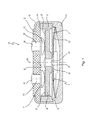
- Fig. 1 is denoted by a temperature-dependent switch 10, which includes a temperature-dependent switching mechanism 11 which is housed in a housing 12.
- the housing 12 comprises a lower part 14 and a closing this upper part 15 which is held by a flanged edge 16 of the lower part 14 at this. Between the lower part 14 and the upper part 15, a ring 17 is arranged, which is supported on a shoulder 18 of the lower part 14 and there leads a spring snap-action disc 21 of the rear derailleur 11 at its edge.
- the rear derailleur 11 additionally comprises, in addition to the spring snap-action disc 21, a bimetal snap-action disc 22 which, together with the spring snap disc 21, is centrally penetrated by a pin-like rivet 23 by which these are mechanically connected to a current transfer member in the form of a contact plate 24.
- the rivet 23 has a first shoulder 25 on which the bimetal snap disc 22 is seated with radial and axial play, with a second shoulder 26 is provided on which the spring snap disc 21 also sits with radial and axial play.
- the bimetallic snap disk 22 is supported with its peripheral edge inside in the lower part 14.
- the already mentioned contact plate 24 has in the direction of the upper part 15 two electrically interconnected, large-area contact surfaces 27 which cooperate with two arranged on the inside 29 of the upper part 29 stationary contacts 31, 32, the inner heads of contact rivets 33, 34 are the pass through the upper part 15 and with their outer heads 35, 36 serve the external connection.
- the bimetal snap-action disc 22 If the temperature of the bimetal snap-action disc 22 increases beyond its response temperature, it snaps from the convex into a concave shape and supports itself with its edge in the region of the ring 17 and pulls the contact plate 24 against the force of the spring. Snap-action disc 21 away from the stationary contacts 31, 32; the switch 10 is now open.
- the upper part 15 made of a PTC thermistor, so represents a PTC resistor, which is electrically connected between the stationary contacts 31, 32.
- the upper part 15 thus acts as a self-holding resistor, as has already been described in detail above.
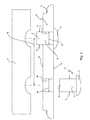
- FIG. 2 schematically shows how the upper part 15 is fitted with the contact rivets 33, 34, each having a setting head 37, 38 in the unformed state, from which a rivet shank 41, 42 extends, having a free end 43, 44 which with Help a schematically indicated at 45 molding tool is converted to closing heads.
- the inner diameter 48, 49 of the through holes 46, 47 and the outer diameter 51, 52 of the contact rivets 33, 34 are matched to each other with very tight tolerances, so that the position of the inner heads 37, 38 and the outer heads 35, 36 on the upper part 15th as accurately as possible.
- the diameters 48, 49, 51, 52 in Fig. 2 are therefore almost the same size.
- the upper part 15 is made of a PTC thermistor material and is solidified after pressing by sintering. In this sintering, the distance between the passage openings 46, 47 indicated at 54 changes slightly so that the two contact rivets 33, 34 can not be inserted into the passage openings 46, 47 simultaneously and fully automatically.
- the new switch 10 can be assembled.
- Fig. 3 the switch 10 is off Fig. 1 shown in an exploded view, the above according to Fig. 2 manufactured upper part 15 can be seen.
- the contact surfaces 27 on the contact plate 24 have such a large extent in the radial direction that the stationary contacts 31, 32 always get into secure contact with the contact surfaces 27, even if their distance to the center line 54 varies due to production.
Landscapes
- Engineering & Computer Science (AREA)
- Manufacturing & Machinery (AREA)
- Physics & Mathematics (AREA)
- Thermal Sciences (AREA)
- Thermally Actuated Switches (AREA)
Abstract
Description
Die vorliegende Erfindung betrifft ein Verfahren zur Herstellung eines temperaturabhängigen Schalters mit einem temperaturabhängigen Schaltwerk, einem das Schaltwerk aufnehmenden Gehäuse, das ein Unterteil sowie ein Oberteil aus Kaltleitermaterial aufweist, zwei sich durch das Oberteil erstreckenden Kontaktnieten, deren innere Köpfe als stationäre Kontakte wirken und deren äußere Köpfe dem Außenanschluss dienen, sowie einem an dem Schaltwerk angeordneten und von diesem bewegten Stromübertragungsglied, das temperaturabhängig mit den beiden stationären Kontakten in Anlage ist, mit den Schritten: Bereitstellen des temperaturabhängigen Schaltwerkes, an dem das Stromübertragungsglied bereits angeordnet ist; Bereitstellen des Unterteils für das Gehäuse; Bereitstellen des aus Kaltleitermaterial gefertigten Oberteils für das Gehäuse, das zwei Durchgangsöffnung zur Aufnahme der beiden Kontaktnieten aufweist; Montieren der beiden Kontaktnieten an den Durchgangsöffnungen; Einlegen des Schaltwerkes in das Unterteil; und Verschließen des Unterteils mit dem Oberteil.The present invention relates to a method for producing a temperature-dependent switch with a temperature-dependent switching mechanism, a housing receiving the switching mechanism having a lower part and a top of PTC thermistor, two extending through the upper part contact rivets whose inner heads act as stationary contacts and the outer Heads serve the external connection, as well as arranged on the derailleur and moved by this current transmission member which is temperature-dependent with the two stationary contacts in the system, comprising the steps of: providing the temperature-dependent switching mechanism on which the current transmitting member is already arranged; Providing the lower part for the housing; Providing the upper part made of PTC resistor material for the housing, which has two passage openings for receiving the two contact rivets; Mounting the two contact rivets on the through holes; Inserting the rear derailleur in the lower part; and closing the lower part with the upper part.
Ein derartiger Schalter ist aus der
Ein vergleichbarer, aus der
In dem Oberteil sitzen zwei Kontaktnieten, deren innere Köpfe als stationäre Kontakte für das Schaltwerk dienen. Die Nietschäfte ragen durch Durchgangsöffnungen in dem Oberteil nach außen und gehen dort in äußere Köpfe über, die dem Außenanschluss des bekannten Schalters dienen. An diese äußeren Köpfe können unmittelbar Anschlusslitzen angelötet werden, wobei es auch bekannt ist, mit den äußeren Köpfen Kontaktwinkel zu halten, an die Anschlusslitzen angelötet oder angecrimpt werden.In the upper part sitting two contact rivets whose inner heads serve as stationary contacts for the rear derailleur. The rivet shanks protrude through through openings in the upper part to the outside and go there in outer heads that serve the external connection of the known switch. Lead wires can be soldered directly to these outer heads, it also being known to maintain contact angles with the outer heads, to be soldered or crimped to the connecting leads.
Das Schaltwerk trägt ein Stromübertragungsglied in Form einer Kontaktbrücke, auf deren Oberseite eine Silberauflage vorgesehen ist, die zwei miteinander verbundene Gegenkontakte aufweist, die je nach Temperatur mit den beiden stationären Kontakten in Anlage gebracht werden und diese dann elektrisch miteinander verbinden.The rear derailleur carries a current transfer member in the form of a contact bridge, on top of which a silver support is provided which has two interconnected mating contacts, which are brought into contact with the two stationary contacts depending on the temperature and then electrically connect them together.
Das temperaturabhängige Schaltwerk weist eine Bimetall-Schnappscheibe sowie eine Feder-Schnappscheibe auf, die zentrisch von einem Zapfen durchsetzt sind, der die Kontaktbrücke trägt. Die Feder-Schnappscheibe ist umfänglich in dem Gehäuse geführt, während sich die Bimetall-Schnappscheibe je nach Temperatur an einer Schulter des Unterteils oder an dem Rand der Feder-Schnappscheibe abstützt und dabei entweder die Anlage der Kontaktbrücke an den beiden stationären Kontakten ermöglicht oder aber die Kontaktbrücke von den stationären Kontakten abhebt, so dass die elektrische Verbindung zwischen den Außenanschlüssen unterbrochen wird.The temperature-dependent switching mechanism has a bimetal snap-action disc and a spring snap-action disc, which are centrally penetrated by a pin which carries the contact bridge. The spring snap-action disk is circumferentially guided in the housing, while the bimetallic snap disk is supported depending on the temperature at a shoulder of the lower part or at the edge of the spring snap disk and thereby allows either the system of contact bridge to the two stationary contacts or the Contact bridge of the stationary contacts lifts so that the electrical connection between the external connections is interrupted.
Dieser temperaturabhängige Schalter wird in bekannter Weise dazu verwendet, elektrische Geräte vor Überhitzung zu schützen. Dazu wird der Schalter elektrisch mit dem zu schützenden Gerät in Reihe geschaltet und mechanisch so an dem Gerät angeordnet, dass er mit diesem in thermischer Verbindung steht.This temperature-dependent switch is used in a known manner to protect electrical equipment from overheating. For this purpose, the switch is electrically connected in series with the device to be protected and mechanically arranged on the device so that it is in thermal communication with this.
Unterhalb der Ansprechtemperatur der Bimetall-Schnappscheibe liegt die Kontaktbrücke an den beiden stationären Kontakten an, so dass der Stromkreis geschlossen ist und das zu schützende Gerät über den Schalter mit Strom versorgt wird. Erhöht sich die Temperatur über einen zulässigen Wert hinaus, so hebt die Bimetall-Schnappscheibe die Kontaktbrücke von den stationären Kontakten ab, wodurch der Schalter geöffnet und die Versorgung des zu schützenden Gerätes unterbrochen wird.Below the response temperature of the bimetallic snap disk, the contact bridge is applied to the two stationary contacts, so that the circuit is closed and the device to be protected is supplied with power via the switch. If the temperature rises above a permissible value, the bimetallic snap-action disc lifts the contact bridge away from the stationary contacts, thus opening the switch and interrupting the supply of the device to be protected.
Das jetzt stromlose Gerät kann sich dann wieder abkühlen. Dabei kühlt sich auch der thermisch an das Gerät angekoppelte Schalter wieder ab, der daraufhin selbsttätig wieder schließt.The now de-energized device can then cool down again. In this case, the thermally coupled to the device switch cools down again, which then automatically closes again.
Durch die Dimensionierung der Kontaktbrücke ist der bekannte Schalter in der Lage, verglichen mit anderen temperaturabhängigen Schaltern, bei denen der Betriebsstrom des zu schützenden Gerätes unmittelbar über die Bimetall-Schnappscheibe oder eine ihr zugeordnete Feder-Schnappscheibe fließt, sehr viel höhere Betriebsströme zu führen, so dass er zum Schützen größerer elektrischer Geräte mit hoher Leistungsaufnahme eingesetzt werden kann.By dimensioning the contact bridge of the known switch is able, compared to other temperature-dependent switches in which the operating current of the device to be protected flows directly through the bimetallic snap disk or its associated spring snap-action, so much higher operating currents to lead that it can be used to protect larger electrical appliances with high power consumption.
Wie bereits erwähnt, schaltet sich der bekannte Schalter nach dem Abkühlen des von ihm geschützten Gerätes selbsttätig wieder ein. Während ein derartiges Schaltverhalten zum Schutz z.B. eines Haartrockners durchaus sinnvoll sein kann, ist dies überall dort nicht erwünscht, wo sich das zu schützende Gerät nach dem Abschalten nicht automatisch wieder einschalten darf, um Beschädigungen zu vermeiden. Dies gilt z.B. für Elektromotoren, die als Antriebsaggregate eingesetzt werden.As already mentioned, the known switch automatically switches on again after cooling the device protected by it. While such a switching behavior for protecting a hair dryer, for example, can be quite useful, this is not desirable anywhere where the device to be protected Do not switch on automatically after switching off to avoid damage. This applies, for example, for electric motors that are used as drive units.
Die eingangs erwähnte
Der aus der
Die
In einem anderen Ausführungsbeispiel ist das Oberteil aus Kaltleitermaterial gefertigt, so dass das Oberteil selbst den Selbsthaltewiderstand bildet.In another embodiment, the upper part is made of PTC material, so that the upper part itself forms the self-holding resistor.
Fertigungsversuche in der Firma des Anmelders haben nun gezeigt, dass sich der aus der
Der bekannte Schalter wird aus Kostengründen daher in der Variante mit einem Oberteil aus einem Isolierstoff hergestellt, auf dessen Innenseite Widerstandsbahnen vorgesehen sind, die als Selbsthaltwiderstand dienen.The known switch is therefore made for cost reasons in the variant with an upper part of an insulating material, on the inside of which resistance paths are provided which serve as self-holding resistance.
Dieser Schalter hat sich zwar bewährt, es wäre jedoch wünschenswert, wenn der Schalter mit einem Oberteil aus Kaltleitermaterial hergestellt werden könnte, weil zum einen die Wärmeausbringung bei dieser Konstruktionsvariante effizienter ist, so dass ein geringerer Reststrom ausreicht, um den Schalter zuverlässig geöffnet zu halten.Although this switch has proven itself, it would be desirable if the switch could be made with a top of PTC thermistor, because on the one hand, the heat dissipation in this design variant is more efficient, so that a lower residual current is sufficient to keep the switch reliably opened.
Ferner stellt ein Selbsthaltewiderstand aus Kaltleitermaterial ein Sicherheitselement dar, denn mit steigender Temperatur steigt auch der Widerstandswert des Selbsthaltewiderstandes und begrenzt so den Reststrom.Furthermore, a self-holding resistor made of PTC thermistor is a safety element, because with increasing temperature, the resistance of the self-holding resistor increases and thus limits the residual current.
Oberteile, also Deckel aus Kaltleitermaterial werden andererseits bei temperaturabhängigen Schaltern bereits eingesetzt. So beschreibt die
Wenn das Schaltwerk wegen zu hoher Temperatur den beweglichen Kontakt von dem stationären Kontakt abhebt, ist der Deckel aus Kaltleitermaterial in Reihe zwischen den stationären Kontakt und das Unterteil geschaltet und führt einen Reststrom, der zu einer hinreichenden Erwärmung des Deckels führt, um das Schaltwerk auf einer Temperatur oberhalb der Schalt- oder Ansprechtemperatur zu halten.If the derailleur lifts the movable contact from the stationary contact because of too high a temperature, the cover made of PTC resistor material is connected in series between the stationary contact and the lower part and guides one Residual current, which leads to a sufficient warming of the lid to keep the derailleur at a temperature above the switching or response temperature.
Der aus der
Ausgehend von diesem Stand der Technik ist es daher Aufgabe der vorliegenden Erfindung, für den eingangs genannten Schalter ein kostengünstiges Herstellungsverfahren mit geringer Ausschussrate anzugeben.Based on this prior art, it is therefore an object of the present invention to specify a cost-effective production method with a low reject rate for the switch mentioned above.
Erfindungsgemäß wird diese Aufgabe bei dem eingangs genannten Verfahren dadurch gelöst, dass die beiden Kontaktnieten nacheinander und unabhängig voneinander in die Durchgangsöffnungen hineingesteckt und danach an dem Oberteil befestigt werden.According to the invention, this object is achieved in the aforementioned method in that the two contact rivets are inserted successively and independently of each other in the through holes and then attached to the upper part.
Die Kontaktnieten werden also zunächst einzeln - sei es manuell oder automatisiert - platziert und danach befestigt. Die Nietschäfte werden dabei getrennt voneinander und nacheinander durch die Durchgangsöffnungen gesteckt. Danach können die beiden Schließköpfe wieder in einem gemeinsamen Fertigungsschritt ausgebildet werden. Die Setzköpfe der Kontaktnieten können dabei sowohl die stationären Kontakte als auch die äußeren Köpfe bilden.The contact rivets are thus first placed individually - be it manually or automatically - and then fastened. The rivet shanks are inserted separately from each other and successively through the passage openings. Thereafter, the two closing heads can be formed again in a common manufacturing step. The setting heads of the contact rivets can form both the stationary contacts and the outer heads.
In der Regel werden jedoch die stationären Kontakte durch die Setzköpfe gebildet, die mit Nietschäften verbunden sind, die durch die Durchgangsöffnungen in dem Oberteil nach außen ragen und dort in die Schließköpfe übergehen, die erst nach dem Durchstecken des Nietschaftes durch die Durchgangsöffnung ausgebildet werden.In general, however, the stationary contacts are formed by the setting heads, which are connected to rivet shanks which protrude through the through holes in the upper part to the outside and there pass into the closing heads, which are formed only after the insertion of the rivet shank through the through hole.
Die der Erfindung zugrundeliegende Aufgabe wird auf diese Weise vollkommen gelöst.The problem underlying the invention is completely solved in this way.
Unter einem "Kaltleitermaterial" wird im Rahmen der vorliegenden Erfindung ein stromleitendes Keramikmaterial verstanden, das einen positiven Temperaturkoeffizienten aufweist, so dass sich ihr elektrischer Widerstand bei steigender Temperatur vergrößert. Der Verlauf des elektrischen Widerstandswertes über der Temperatur ist dabei nichtlinear.In the context of the present invention, a "PTC resistor material" is understood to mean an electrically conductive ceramic material which has a positive temperature coefficient, so that its electrical resistance increases as the temperature increases. The course of the electrical resistance value over the temperature is non-linear.
Derartige Kaltleiter werden im Rahmen der vorliegenden Erfindung auch als PTC-Widerstände bezeichnet. Sie werden beispielsweise aus halbleitenden, polykristallinen Keramiken wie BaTiO3 gefertigt.Such PTC thermistors are referred to in the context of the present invention as PTC resistors. They are made, for example, from semiconductive, polycrystalline ceramics such as BaTiO 3 .
Zur Herstellung der PTC-Deckel werden Mischungen von Barium-und Titanverbindungen sowie anderen Materialien, die zusammen die gewünschten elektrischen und thermischen Eigenschaften ergeben, in eine Form mit den gewünschten geometrischen Abmaßen und Durchgangsöffnungen gepresst und anschließend bei hohen Temperaturen gesintert.To produce the PTC caps, blends of barium and titanium compounds and other materials which together give the desired electrical and thermal properties are pressed into a mold having the desired geometric dimensions and through-holes and then sintered at high temperatures.
Der Erfinder der vorliegenden Anmeldung hat in diesem Zusammenhang erkannt, dass sich durch das Sintern die Geometrie der Deckel so verändert, die geometrische Position der Durchgangsöffnungen variiert. Sowohl ihr Abstand zueinander als auch ihr Abstand zur Deckelmitte ändert sich beim Sintern auf unvorhersehbare Weise.The inventor of the present application has recognized in this connection that the geometry of the cover changes as a result of the sintering, the geometric position of the passage openings varies. Both their distance from each other and their distance from the center of the lid changes in an unpredictable manner during sintering.
Zwar wird bei dieser Fertigung die Materialschrumpfen berücksichtigt, aber bei zwei Durchgangslöchern lässt sich zwar das Schrumpfen der Durchmesser nicht aber die Veränderung des Abstandes mit hinreichender Genauigkeit vorhersagen.Although the material shrinkage is taken into account in this production, but with two through holes, the shrinkage of the diameter but not the change in the distance can be predicted with sufficient accuracy.
Mit anderen Worten, die Lage der Durchgangsöffnungen variiert, und zwar sowohl zwischen PTC-Deckeln aus verschiedenen Chargen als auch zwischen PTC-Deckeln aus einer einzigen Charge. Bei PTC-Deckeln mit einer zentrischen Durchgangsöffnung, wie sie aus der oben erwähnten
Die Variation in dem Abstand der Durchgangsbohrungen hat nun bei den bisherigen Fertigungsversuchen dazu geführt, dass die aus Gründen der Effizienz immer gemeinsam, also mit festem Abstand zueinander automatisch zugeführten Kontaktnieten nicht immer genau oberhalb der Durchgangsöffnungen positioniert wurden.The variation in the distance of the through holes has now led to the previous production attempts that the reasons of efficiency always together, so with a fixed distance automatically supplied to each other contact rivets were not always positioned exactly above the passage openings.
Dies hat dann entweder bereits während der Montage der Kontaktnieten oder aber bei einem späteren Fertigungsschritt, beispielsweise beim Verschließen des Unterteils mit dem Oberteil, dazu geführt, dass das Oberteil gesprungen oder gar ganz zerbrochen ist.This has then either already during assembly of the contact rivets or at a later manufacturing step, for example, when closing the lower part with the upper part, led to the fact that the upper part is cracked or even completely broken.
Wenn die Kontaktnieten dagegen erfindungsgemäß getrennt voneinander zugeführt werden, kann bei automatischer Bestückung jeweils vorher die genaue Lage der einzelnen Durchgangsöffnungen bestimmt werden. Dies bedeutet jedoch, dass die entsprechenden Fertigungsautomaten entweder mit einem Bilderkennungssystem oder mit einem Messtaster versehen sein müssen, um die genaue Lage der beiden Durchgangsöffnungen für jedes einzelne Oberteil zu bestimmen, bevor er mit den Kontaktnieten bestückt wird.On the other hand, if the contact rivets are supplied separately from one another according to the invention, the exact position of the individual passage openings can be determined beforehand in the case of automatic assembly. However, this means that the corresponding production machines must be provided with either an image recognition system or with a probe to determine the exact location of the two through holes for each individual shell before it is fitted with the contact rivets.
Dabei ist zu bedenken, dass die Oberteile häufig als Schüttgut vorrätig gehalten werden, so dass in dem Vorratsbehälter Oberteile aus unterschiedlichen Chargen vorhanden sind, und die Lage der Durchgangsöffnungen entsprechend breit streut.It should be noted that the tops are often kept in bulk as bulk, so that in the reservoir tops from different batches are available, and the position of the passage openings scatters wide accordingly.
Bevorzugt ist es daher, wenn die Oberteile manuell mit den beiden Kontaktnieten bestückt werden.It is therefore preferred if the tops are fitted manually with the two contact rivets.
Der Erfinder ist also nicht den sich auf den ersten Blick anbietenden Weg gegangen, den Durchmesser des Nietschaftes zu verringern oder die lichte Weite der Durchgangsöffnungen zu vergrößern.The inventor has therefore not gone the way offering itself at first glance, to reduce the diameter of the rivet shank or to increase the clear width of the through holes.
Die Veränderung der Durchmesser hätte nämlich den Nachteil, dass die Positionen der inneren und äußeren Köpfe nicht mehr reproduzierbar bekannt wären, so dass es Probleme mit der Kontaktgabe an dem Stromübertragungsglied geben könnte. Ferner wäre das Anschließen an die äußeren Köpfe nicht mehr vollautomatisch realisierbar.Namely, the change of the diameters would have the disadvantage that the positions of the inner and outer heads would no longer be known reproducibly, so that there could be problems with the contact on the current transmitting member. Furthermore, the connection to the outer heads would no longer be fully automatic feasible.
Geringere Durchmesser der Nietschäfte könnten zudem Probleme bei den hohen Strömen von über 10 A bis zu 25 A und mehr mit sich bringen, für die der Schalter vorgesehen ist. Die Nietschäfte müssen diese Stromstärken leiten können, ohne Durchzubrennen oder zu heiß zu werden.Lower diameter of the rivet shanks could also cause problems with the high currents of over 10 A up to 25 A and more, for which the switch is intended. The rivet shafts must be able to conduct these currents without being burned or getting too hot.
Daher hat der Erfinder der vorliegenden Anmeldung den auf den ersten Blick ungewöhnlichen Weg gewählt, die Bestückung der Oberteile entweder hochautomatisiert oder alternativ von Hand vornehmen zu lassen. Obwohl die Bestückung von Hand unter Automatisierungsgesichtspunkten nachteilig zu sein scheint, ermöglicht dieser manuelle Schritt es, alle anderen Schritte vollautomatisch durchzuführen, und bei engen Toleranzen zwischen Durchgangsöffnung und Nietschaft dennoch eine Fertigung mit geringer Ausschussrate zu gewährleisten.Therefore, the inventor of the present application has chosen the unusual at first glance way to make the placement of the tops either highly automated or alternatively by hand. Although hand assembly appears to be disadvantageous from an automation standpoint, this manual step allows for all other steps to be performed fully automatically, yet still provides low rejection production with tight tolerances between port and rivet shank.
Das Schaltwerk kann dabei eine Bimetall-Schnappscheibe umfassen, die für den Schließdruck und die temperaturabhängige Öffnungsbewegung sorgt. Der Schließdruck kann aber auch allein oder zusätzlich durch eine Federschnappscheibe aufgebracht werden, während eine Bimetall-Schnappscheibe vorgesehen ist, die entweder nur für die Öffnungsbewegung sorgt oder aber in ihrer Tieftemperaturstellung auch zu dem Kontaktdruck beiträgt.The derailleur can include a bimetallic snap disk, which ensures the closing pressure and the temperature-dependent opening movement. The closing pressure can also be applied alone or in addition by a Federschnappscheibe, while a bimetallic snap disk is provided, which either provides only for the opening movement or contributes to the contact pressure in its low temperature position.
Daher ist es bevorzugt, wenn das Schaltwerk eine Bimetall-Schnappscheibe umfasst, die mechanisch mit dem Stromübertragungsglied verbunden ist und dieses unterhalb ihrer Schalttemperatur gegen die stationären Kontakte drückt und oberhalb ihrer Schalttemperatur von diesen abhebt.Therefore, it is preferred if the derailleur comprises a bimetal snap-action disc which is mechanically connected to the current transfer member and this presses below its switching temperature against the stationary contacts and lifts above their switching temperature of these.
Andererseits ist es bevorzugt, wenn eine Feder-Schnappscheibe, die das Stromübertragungsglied im Sinne einer Anlage an die stationären Kontakte vorspannt, und ferner eine Bimetall-Schnappscheibe vorgesehen ist, die das Stromübertragungsglied oberhalb ihrer Schalttemperatur von den stationären Kontakten abhebt, wobei ferner vorzugsweise die Feder-Schnappscheibe zwischen Stromübertragungsglied und Bimetall-Schnappscheibe angeordnet ist.On the other hand, it is preferred if a spring snap-action disc, which biases the current transfer member in the sense of an abutment against the stationary contacts, and also a bimetallic snap disk is provided, which lifts the current transfer member above its switching temperature of the stationary contacts, and further preferably the spring -Schnappscheibe between the current transmitting member and bimetallic snap disk is arranged.
Während es nämlich durchaus genügt, wenn lediglich eine Bimetall-Schnappscheibe vorgesehen ist, die sowohl den Kontaktdruck herstellt als auch für das temperaturabhängige Öffnen sorgt, kann durch eine Feder-Schnappscheibe, die zusätzlich zur Bimetall-Schnappscheibe oder allein den Kontaktdruck bewirkt, die Bimetall-Schnappscheibe in ihrer Tieftemperaturstellung mechanisch entlastet werden, was zu einer größeren Langzeitstabilität ihres Schaltverhaltens beiträgt.While it is quite sufficient, if only a bimetallic snap disk is provided which produces both the contact pressure and provides for the temperature-dependent opening, can by a spring-snap disk, which in addition to the bimetallic snap disk or alone causes the contact pressure, the bimetallic Snap disk are relieved of mechanical stress in their low temperature position, which contributes to greater long-term stability of their switching behavior.
Weiter ist es bevorzugt, wenn das Stromübertragungsglied ein etwa runder Kontaktteller ist, der auf seiner den stationären Kontakten zugewandten Oberfläche mit zwei elektrisch miteinander verbundenen Kontaktflächen versehen ist.Further, it is preferred if the current transmission member is an approximately round contact plate, which is provided on its surface facing the stationary contacts with two electrically interconnected contact surfaces.
Die Kontaktflächen weisen dabei jeweils eine so große Kontaktfläche auf, dass sie auch bei fertigungsbedingter Schwankung der Lage der stationären Kontakte mit diesen sicher in Anlage gelangen und somit den Schalter zuverlässig schließen.The contact surfaces in each case have such a large contact surface, that even with production-related fluctuation of the position of the stationary contacts with these safely come into contact and thus reliably close the switch.
Der Kontaktteller ist vorzugsweise durch einen zapfenartigen Niet zentrisch mit der Bimetall-Schnappscheibe und ggf. der Feder-Schnappscheibe verbunden.The contact plate is preferably connected by a pin-like rivet centric with the bimetallic snap disk and possibly the spring snap-action disc.
Hier ist von Vorteil, dass das gesamte Schaltwerk während der Fertigung als gesonderte Einheit zu handhaben ist und somit vorgefertigt zwischengelagert werden kann.Here it is advantageous that the entire rear derailleur is to be handled during production as a separate unit and thus prefabricated can be stored.
Weitere Vorteile ergeben sich aus der Beschreibung und der beigefügten Zeichnung.Further advantages will become apparent from the description and the accompanying drawings.
Es versteht sich, dass die vorstehend genannten und die nachstehend noch zu erläuternden Merkmale nicht nur in der jeweils angegebenen Kombination, sondern auch in anderen Kombinationen oder in Alleinstellung verwendbar sind, ohne den Rahmen der vorliegenden Erfindung zu verlassen.It is understood that the features mentioned above and those yet to be explained below can be used not only in the particular combination given, but also in other combinations or in isolation, without departing from the scope of the present invention.
Ausführungsbeispiele der Erfindung sind in der beigefügten Zeichnung dargestellt und werden in der nachfolgenden Beschreibung näher erläutert. Es zeigen:
- Fig. 1
- einen schematischen, nicht maßstabsgetreuen Längsschnitt durch den neuen Schalter;
- Fig. 2
- in einer schematischen Seitenansicht die Bestückung des Oberteils für den Schalter aus
Fig. 1 mit stationären Kontakten; und - Fig. 3
- den Schalter aus
Fig. 1 in einer schematischen Explosionsdarstellung in Seitenansicht, um den Zusammenbau der einzelnen Komponenten zu verdeutlichen.
- Fig. 1
- a schematic, not to scale longitudinal section through the new switch;
- Fig. 2
- in a schematic side view of the assembly of the upper part of the switch
Fig. 1 with inpatient contacts; and - Fig. 3
- the switch off
Fig. 1 in a schematic exploded view in side view to illustrate the assembly of the individual components.
In
Das Gehäuse 12 umfasst ein Unterteil 14 sowie ein dieses verschließendes Oberteil 15, das durch einen umgebördelten Rand 16 des Unterteils 14 an diesem gehalten wird. Zwischen dem Unterteil 14 und dem Oberteil 15 ist ein Ring 17 angeordnet, der sich auf einem Absatz 18 des Unterteils 14 abstützt und dort eine Feder-Schnappscheibe 21 des Schaltwerkes 11 an ihrem Rand führt.The
Das Schaltwerk 11 umfasst zusätzlich zu der Feder-Schnappscheibe 21 noch eine Bimetall-Schnappscheibe 22, die zusammen mit der Feder-Schnappscheibe 21 zentrisch von einem zapfenartigen Niet 23 durchgriffen wird, durch den diese mit einem Stromübertragungsglied in Form eines Kontakttellers 24 mechanisch verbunden sind. Der Niet 23 weist einen ersten Absatz 25 auf, auf dem die Bimetall-Schnappscheibe 22 mit radialem und axialem Spiel sitzt, wobei ein zweiter Absatz 26 vorgesehen ist, auf dem die Feder-Schnappscheibe 21 ebenfalls mit radialem und axialem Spiel sitzt.The
Die Bimetall-Schnappscheibe 22 stützt sich mit ihrem umlaufenden Rand innen in dem Unterteil 14 ab.The
Der bereits erwähnte Kontaktteller 24 weist in Richtung des Oberteils 15 zwei elektrisch miteinander verbundene, großflächige Kontaktflächen 27 auf, die mit zwei an der Innenseite 29 des Oberteils 29 angeordneten stationären Kontakten 31, 32 zusammenwirken, die innere Köpfe von Kontaktnieten 33, 34 sind, die das Oberteil 15 durchgreifen und mit ihren äußeren Köpfen 35, 36 dem Außenanschluss dienen.The already mentioned
In der in
Erhöht sich die Temperatur der Bimetall-Schnappscheibe 22 über ihre Ansprechtemperatur hinaus, so schnappt sie von der gezeigten konvexen in eine konkave Form um und stützt sich dabei mit ihrem Rand im Bereich des Ringes 17 ab und zieht den Kontaktteller 24 gegen die Kraft der Feder-Schnappscheibe 21 von den stationären Kontakten 31, 32 weg; der Schalter 10 ist jetzt geöffnet.If the temperature of the bimetal snap-
Der insoweit beschriebene Schalter ist aus der
Wie bei dem aus der
In
Zunächst ist zu erkennen, dass in dem Oberteil 15 zwei Durchgangsöffnungen 46, 47 vorgesehen sind, deren Innendurchmesser 48, 49 etwa dem Außendurchmesser 51, 52 der Nietschäfte 41, 42 entspricht.First, it can be seen that two through-
In den Durchgangsöffnungen 47, 48 werden zunächst die Kontaktnieten 33, 34 so platziert, dass deren Setzköpfe 37, 38 an der Innenseite 29 des Oberteiles 15 zu liegen kommen und dort die stationären Kontakte 31, 32 bilden. Die Nietschäfte 41, 42 ragen dabei durch die Durchgangsöffnungen 46, 47 hindurch auf die Oberseite 53 des Oberteils 15, wo sie mit ihren freien Enden 43, 44 herausragen.In the through-
In
Sobald beide Kontaktnieten 33, 34 in den Durchgangsöffnungen 46, 47 sitzen, werden ihre oberen freien Enden 43, 44 mit dem oberhalb des Oberteiles 15 schematisch angedeuteten Formwerkzeug 45 zu den äußeren Köpfen 35, 36 umgeformt, die in
Der Innendurchmesser 48, 49 der Durchgangsöffnungen 46, 47 und der Außendurchmesser 51, 52 der Kontaktnieten 33, 34 sind dabei mit sehr engen Toleranzen aufeinander abgestimmt, damit die Lage der inneren Köpfe 37, 38 sowie der äußeren Köpfe 35, 36 an dem Oberteil 15 möglichst genau festgelegt wird. Die Durchmesser 48, 49, 51, 52 in
Das Oberteil 15 besteht aus einem Kaltleitermaterial und wird nach dem Pressen durch Sintern verfestigt. Bei diesem Sintern ändert sich der bei 54 angedeutete Abstand zwischen den Durchgangsöffnungen 46, 47 geringfügig, so dass die beiden Kontaktnieten 33, 34 nicht gleichzeitig und vollautomatisch in die Durchgangsöffnungen 46, 47 hineingesteckt werden können.The
Da der genaue Abstand 54 zwischen den Durchgangsöffnungen 46, 47 schon zwischen Oberteilen 15 aus der gleichen Fertigungscharge variieren kann, muss auch der Abstand 54 der beiden Kontaktnieten 33, 34 beim Bestücken des Oberteiles 15 variabel sein.Since the
Dies wird dadurch erreicht, dass die Kontaktnieten 33, 34 nacheinander in die Durchgangsöffnungen 46, 47 eingesteckt werden, obwohl eigentlich bei einer vollautomatischen Fertigung das gleichzeitige Einstecken bevorzugt ist.This is achieved in that the contact rivets 33, 34 are inserted one after the other into the
Dieses Einstecken der Kontaktnieten 46, 47 kann zum einen von Hand erfolgen, was zwar einen Nachteil bei der gewünschten vollautomatischen Fertigung darstellt, jedoch andererseits sicherstellt, dass die mit den Kontaktnieten 33, 34 bestückten Oberteile 15 bei dem Ausformen der äußeren Köpfe 35, 36 sowie dem anschließenden Verbauen in den temperaturabhängigen Schaltern 10 nicht platzen, springen oder zerbrechen.This insertion of the contact rivets 46, 47 can be done by hand, which is a disadvantage in the desired fully automatic production, but on the other hand ensures that the equipped with the contact rivets 33, 34 tops 15 in the molding of the
Andererseits ist es auch möglich, bei einer hochautomatisierten Maschine zunächst für jedes Oberteil 15 die Lage der Durchgangsöffnungen 46, 47 auf automatische Weise genau zu bestimmen und dann die beiden Kontaktnieten 33, 34 nacheinander automatisiert einzubringen.On the other hand, it is also possible in a highly automated machine first for each
Während in dem Schalter 10 der
Nachdem das Oberteil 15 auf die beschriebene Weise mit den beiden Kontaktnieten 33, 34 bestückt und die Kontaktnieten 33, 34 danach montiert wurden, indem die Schließköpfe ausgebildet wurden, kann der neue Schalter 10 zusammengebaut werden.After the
In
Unter dem Oberteil 15 befinden sich der Distanzring 17 und darunter das Schaltwerk 11 mit dem Kontaktteller 24 sowie der Bimetall-Schnappscheibe 22 und der Federschnappscheibe 21.Under the
Ganz unten in
In der gezeigten Reihenfolge werden jetzt sowohl das Schaltwerk 11 als auch der Ring 17 und danach das Oberteil 15 in das Unterteil 14 eingelegt, woraufhin dann der hochgezogene Rand 16 umgebördelt wird, so dass sich der Schalter 10 aus
All diese Schritte sind vollautomatisch durchzuführen, wobei auch die Montage des Schaltwerkes 11 aus den verschiedenen Einzelteilen vollautomatisch möglich ist.All these steps are fully automatic to perform, with the assembly of the
Lediglich bei der Bestückung des Oberteiles 15 mit den Kontaktnieten 33, 34 ist ein manueller Schritt vorgesehen, der zum einen die automatische Fertigung nicht wirklich behindert, zum anderen aber auf elegante Weise dafür sorgt, dass der Ausschuss bei der Produktion der Oberteile 15 oder der neuen Schalter 10 sehr gering ist, selbst wenn die Toleranzen zwischen den Durchmessern 48, 49, 51, 52 der Durchgangsöffnungen 46, 47 und der Nietschäfte 41, 42 sehr eng sind.Only in the assembly of the
Diese engen Toleranzen werden gewünscht, damit einerseits die Durchmesser 51, 52 der Nietschäfte 41, 42 so groß wie möglich ausgelegt sein können, um die hohen Ströme von 25 A und mehr führen zu können. Andererseits sollen die Durchgangsöffnungen 46, 47 in dem Oberteil 15 so kleine Durchmesser 48, 49 wie möglich aufweisen, damit die Stabilität des aus Kaltleitermaterial gefertigten Oberteiles 15 nicht leidet.These tight tolerances are desired so that on the one hand the
Neben dem fertigungsbedingt nicht exakt reproduzierbaren und ungleichmäßig variierenden Abstand 54 zwischen den Durchgangsöffnungen 46, 47 liegen bei einem mit den Kontaktnieten 33, 34 vorkonfektionierten Oberteil 15 die stationären Kontakte 31, 32 zudem nicht symmetrisch zu der in
Die Kontaktflächen 27 auf dem Kontaktteller 24 weisen jedoch eine so große Ausdehnung in radialer Richtung aus, dass die stationären Kontakte 31, 32 immer sicher in Anlage mit den Kontaktflächen 27 gelangen, auch wenn ihr Abstand zu der Mittellinie 54 fertigungsbedingt variiert.However, the contact surfaces 27 on the
Claims (9)
Applications Claiming Priority (1)
| Application Number | Priority Date | Filing Date | Title |
|---|---|---|---|
| DE102011015116A DE102011015116A1 (en) | 2011-03-22 | 2011-03-22 | Method for producing a temperature-dependent switch |
Publications (1)
| Publication Number | Publication Date |
|---|---|
| EP2503576A1 true EP2503576A1 (en) | 2012-09-26 |
Family
ID=45954305
Family Applications (1)
| Application Number | Title | Priority Date | Filing Date |
|---|---|---|---|
| EP12158572A Withdrawn EP2503576A1 (en) | 2011-03-22 | 2012-03-08 | Method for producing a temperature-dependent switch |
Country Status (2)
| Country | Link |
|---|---|
| EP (1) | EP2503576A1 (en) |
| DE (1) | DE102011015116A1 (en) |
Cited By (1)
| Publication number | Priority date | Publication date | Assignee | Title |
|---|---|---|---|---|
| EP2874171A1 (en) * | 2013-10-17 | 2015-05-20 | Thermik Gerätebau GmbH | Temperature-dependent switching device |
Families Citing this family (2)
| Publication number | Priority date | Publication date | Assignee | Title |
|---|---|---|---|---|
| DE102023104839B3 (en) * | 2023-02-28 | 2024-05-16 | Marcel P. HOFSAESS | Temperature dependent switch |
| DE102023104830B3 (en) * | 2023-02-28 | 2024-05-16 | Marcel P. HOFSAESS | Temperature dependent switch |
Citations (4)
| Publication number | Priority date | Publication date | Assignee | Title |
|---|---|---|---|---|
| DE2644411C2 (en) | 1976-10-01 | 1984-08-16 | Hofsäss, Peter, 7530 Pforzheim | Temperature monitor |
| DE19609577A1 (en) * | 1996-03-12 | 1997-09-18 | Thermik Geraetebau Gmbh | Switch with a temperature-dependent switching mechanism |
| DE19517310C2 (en) | 1995-05-03 | 1999-12-23 | Thermik Geraetebau Gmbh | Component made of thermistor material and temperature monitor with such a component |
| DE19827113A1 (en) | 1998-06-18 | 1999-12-30 | Marcel Hofsaes | Temperature-dependent switch with current transfer element |
-
2011
- 2011-03-22 DE DE102011015116A patent/DE102011015116A1/en not_active Withdrawn
-
2012
- 2012-03-08 EP EP12158572A patent/EP2503576A1/en not_active Withdrawn
Patent Citations (5)
| Publication number | Priority date | Publication date | Assignee | Title |
|---|---|---|---|---|
| DE2644411C2 (en) | 1976-10-01 | 1984-08-16 | Hofsäss, Peter, 7530 Pforzheim | Temperature monitor |
| DE19517310C2 (en) | 1995-05-03 | 1999-12-23 | Thermik Geraetebau Gmbh | Component made of thermistor material and temperature monitor with such a component |
| DE19609577A1 (en) * | 1996-03-12 | 1997-09-18 | Thermik Geraetebau Gmbh | Switch with a temperature-dependent switching mechanism |
| DE19827113A1 (en) | 1998-06-18 | 1999-12-30 | Marcel Hofsaes | Temperature-dependent switch with current transfer element |
| DE19827113C2 (en) | 1998-06-18 | 2001-11-29 | Marcel Hofsaes | Temperature-dependent switch with current transfer element |
Cited By (2)
| Publication number | Priority date | Publication date | Assignee | Title |
|---|---|---|---|---|
| EP2874171A1 (en) * | 2013-10-17 | 2015-05-20 | Thermik Gerätebau GmbH | Temperature-dependent switching device |
| US10256061B2 (en) | 2013-10-17 | 2019-04-09 | Thermik Geraetebau Gmbh | Temperature-dependent switching mechanism |
Also Published As
| Publication number | Publication date |
|---|---|
| DE102011015116A1 (en) | 2012-09-27 |
Similar Documents
| Publication | Publication Date | Title |
|---|---|---|
| EP0966014B1 (en) | Thermally actuated switch having a current conducting member | |
| DE102008048554B3 (en) | Temperature-dependent switch | |
| DE102011101862B4 (en) | Temperature-dependent switch with current transfer element | |
| EP0920044B1 (en) | Switch with a temperature sensitive switching mechanism | |
| EP2846344B1 (en) | Temperature-dependent switch | |
| DE102011119632B3 (en) | Temperature-dependent derailleur | |
| DE102007014237A1 (en) | Temperature-dependent switch and dedicated rear derailleur | |
| EP2747110B1 (en) | Overtemperature protection circuit | |
| DE102011119637B4 (en) | Temperature-dependent switch with a temperature-dependent switching mechanism and method for producing such a switch | |
| EP0951040B1 (en) | Thermally actuated switch | |
| EP2503581B1 (en) | Temperature-dependent circuit with power transmission element | |
| DE102014108518A1 (en) | Temperature-dependent switch with spacer ring | |
| DE19636640C2 (en) | Switch with a security element | |
| EP2503576A1 (en) | Method for producing a temperature-dependent switch | |
| EP4411777A1 (en) | Temperature-dependent switch | |
| EP2038905B1 (en) | Connection pot and switch with connection pot | |
| EP0740323A2 (en) | Thermostat with a bimetal switch device switching at overheating | |
| EP2506281B1 (en) | Temperature-dependent circuit with series resistor | |
| DE102013108504C5 (en) | Temperature-dependent switch | |
| DE2511214C2 (en) | Temperature control device for electrical devices | |
| DE102011016133B4 (en) | Temperature-dependent switch with series resistor | |
| DE102011104984B4 (en) | Temperature-dependent switch with heating resistor on carrier plate | |
| DE102011122890A1 (en) | Temperature-dependent switch has contact element that is detached from support region of spring snap disc over portion of peripheral region by gap | |
| EP4528772A2 (en) | Temperature-dependent switching device and temperature-dependent switch | |
| DE102004014028A1 (en) | Protective temperature limiting switch for electrical equipment protection, has bimetallic disk which inverts against action of spring disk when temperature exceeds set point |
Legal Events
| Date | Code | Title | Description |
|---|---|---|---|
| PUAI | Public reference made under article 153(3) epc to a published international application that has entered the european phase |
Free format text: ORIGINAL CODE: 0009012 |
|
| AK | Designated contracting states |
Kind code of ref document: A1 Designated state(s): AL AT BE BG CH CY CZ DE DK EE ES FI FR GB GR HR HU IE IS IT LI LT LU LV MC MK MT NL NO PL PT RO RS SE SI SK SM TR |
|
| AX | Request for extension of the european patent |
Extension state: BA ME |
|
| 17P | Request for examination filed |
Effective date: 20130313 |
|
| 17Q | First examination report despatched |
Effective date: 20131203 |
|
| STAA | Information on the status of an ep patent application or granted ep patent |
Free format text: STATUS: THE APPLICATION HAS BEEN WITHDRAWN |
|
| 18W | Application withdrawn |
Effective date: 20140412 |