EP2503516A2 - Détection de ralenti pour améliorer l'efficacité de consommation de carburant dans un véhicule - Google Patents
Détection de ralenti pour améliorer l'efficacité de consommation de carburant dans un véhicule Download PDFInfo
- Publication number
- EP2503516A2 EP2503516A2 EP12160798A EP12160798A EP2503516A2 EP 2503516 A2 EP2503516 A2 EP 2503516A2 EP 12160798 A EP12160798 A EP 12160798A EP 12160798 A EP12160798 A EP 12160798A EP 2503516 A2 EP2503516 A2 EP 2503516A2
- Authority
- EP
- European Patent Office
- Prior art keywords
- vehicle
- idling
- processor
- engine
- voltage
- Prior art date
- Legal status (The legal status is an assumption and is not a legal conclusion. Google has not performed a legal analysis and makes no representation as to the accuracy of the status listed.)
- Withdrawn
Links
- 239000000446 fuel Substances 0.000 title description 13
- 238000001514 detection method Methods 0.000 title description 8
- 230000033001 locomotion Effects 0.000 claims abstract description 22
- 238000012545 processing Methods 0.000 claims abstract description 5
- 238000000034 method Methods 0.000 claims description 44
- 230000001133 acceleration Effects 0.000 claims description 15
- 230000008859 change Effects 0.000 claims description 12
- 230000003595 spectral effect Effects 0.000 claims description 2
- 230000008569 process Effects 0.000 description 17
- 238000004891 communication Methods 0.000 description 16
- 238000013459 approach Methods 0.000 description 11
- 230000005540 biological transmission Effects 0.000 description 5
- 238000001914 filtration Methods 0.000 description 5
- 230000003287 optical effect Effects 0.000 description 5
- 230000008901 benefit Effects 0.000 description 4
- 238000012544 monitoring process Methods 0.000 description 4
- 230000006399 behavior Effects 0.000 description 3
- 238000004364 calculation method Methods 0.000 description 3
- 230000007246 mechanism Effects 0.000 description 3
- 239000000523 sample Substances 0.000 description 3
- 238000005070 sampling Methods 0.000 description 3
- 230000015556 catabolic process Effects 0.000 description 2
- 238000013500 data storage Methods 0.000 description 2
- 238000006731 degradation reaction Methods 0.000 description 2
- 238000010586 diagram Methods 0.000 description 2
- 239000007787 solid Substances 0.000 description 2
- 230000003068 static effect Effects 0.000 description 2
- RYGMFSIKBFXOCR-UHFFFAOYSA-N Copper Chemical compound [Cu] RYGMFSIKBFXOCR-UHFFFAOYSA-N 0.000 description 1
- QAOWNCQODCNURD-UHFFFAOYSA-N Sulfuric acid Chemical compound OS(O)(=O)=O QAOWNCQODCNURD-UHFFFAOYSA-N 0.000 description 1
- 230000002776 aggregation Effects 0.000 description 1
- 238000004220 aggregation Methods 0.000 description 1
- 238000004458 analytical method Methods 0.000 description 1
- 238000003491 array Methods 0.000 description 1
- 238000002485 combustion reaction Methods 0.000 description 1
- 238000012937 correction Methods 0.000 description 1
- 230000007797 corrosion Effects 0.000 description 1
- 238000005260 corrosion Methods 0.000 description 1
- 230000008878 coupling Effects 0.000 description 1
- 238000010168 coupling process Methods 0.000 description 1
- 238000005859 coupling reaction Methods 0.000 description 1
- 230000008030 elimination Effects 0.000 description 1
- 238000003379 elimination reaction Methods 0.000 description 1
- 238000011156 evaluation Methods 0.000 description 1
- 239000000835 fiber Substances 0.000 description 1
- 230000006870 function Effects 0.000 description 1
- 238000009434 installation Methods 0.000 description 1
- 230000007774 longterm Effects 0.000 description 1
- 238000005259 measurement Methods 0.000 description 1
- 230000006855 networking Effects 0.000 description 1
- 230000009467 reduction Effects 0.000 description 1
- 230000004044 response Effects 0.000 description 1
- 230000007704 transition Effects 0.000 description 1
- 238000010792 warming Methods 0.000 description 1
- XLYOFNOQVPJJNP-UHFFFAOYSA-N water Substances O XLYOFNOQVPJJNP-UHFFFAOYSA-N 0.000 description 1
Images
Classifications
-
- G—PHYSICS
- G07—CHECKING-DEVICES
- G07C—TIME OR ATTENDANCE REGISTERS; REGISTERING OR INDICATING THE WORKING OF MACHINES; GENERATING RANDOM NUMBERS; VOTING OR LOTTERY APPARATUS; ARRANGEMENTS, SYSTEMS OR APPARATUS FOR CHECKING NOT PROVIDED FOR ELSEWHERE
- G07C5/00—Registering or indicating the working of vehicles
- G07C5/08—Registering or indicating performance data other than driving, working, idle, or waiting time, with or without registering driving, working, idle or waiting time
-
- G—PHYSICS
- G07—CHECKING-DEVICES
- G07C—TIME OR ATTENDANCE REGISTERS; REGISTERING OR INDICATING THE WORKING OF MACHINES; GENERATING RANDOM NUMBERS; VOTING OR LOTTERY APPARATUS; ARRANGEMENTS, SYSTEMS OR APPARATUS FOR CHECKING NOT PROVIDED FOR ELSEWHERE
- G07C5/00—Registering or indicating the working of vehicles
- G07C5/008—Registering or indicating the working of vehicles communicating information to a remotely located station
Definitions
- the present disclosure generally relates to monitoring the operation of vehicles, and more particularly to techniques for improving the vehicle's fuel consumption.
- Fuel cost constitutes a significant part of the vehicle owner's daily expenses, and is even more significant when it comes to vehicle fleets.
- fuel consumption due to unnecessary vehicle idling i.e., keeping the engine running while the vehicle remains stationary for an extended period of time
- Unnecessary idling often represents about 5% or more of the overall fuel consumption, therefore minimizing the unnecessary idling entails a big impact upon fleet cost savings and emissions' reductions.
- a vehicle is considered to be idling anytime when the engine is running while the vehicle is stationary. However, not all of these idling periods are considered to be unnecessary. Short duration idling periods e.g. at traffic lights, stop signs, etc., are typically viewed as being situations in which idling is unavoidable or not significant enough from a fuel saving perspective, to target them for elimination, while longer idling periods are found typically to be unnecessary idling periods.
- improving the vehicle's fuel consumption is achieved by identifying a plurality of unnecessary idling periods associated with a vehicle and/or unnecessary idling periods attributed to a certain driver.
- visibility of information about unnecessary idling is provided to drivers and managers, which in turn allows drivers to self-correct their behaviour and to essentially eliminate unnecessary idling periods.
- consistent idling performance assessments are provided across various vehicle types.
- various approaches enable customizing the system, in order to address specific operating environments and needs within users' vehicle fleets.
- approaches are provided to automatically collect and analyze all idling information, and to provide feedback based on the idling information retrieved via a secured web portal.
- a system is configured for identifying a plurality of unnecessary idling periods associated with a vehicle and/or attributed to a certain driver, comprising:
- the first sensor is operative to retrieve the vehicle's battery voltage output and to detect therefrom changes in the vehicle's operational status.
- the first sensor is adapted to detect one or more voltage signatures or patterns in the vehicle's battery voltage output.
- Each of the voltage signatures is associated with an operational mode of the vehicle's engine.
- the system provided further comprises a memory means, and wherein the processor is configured to determine based on one or more indications received from at least one of the first and second sensors, that the vehicle is currently in a moving mode (e.g, at a speed that exceeds a pre-defined threshold, or if the vehicle is accelerating), and to store at the memory means a voltage signature comprised in the corresponding vehicle's battery voltage output.
- a moving mode e.g., at a speed that exceeds a pre-defined threshold, or if the vehicle is accelerating
- system provided further comprises a memory means, and wherein the processor is configured to store at the memory means a voltage signature comprised in the vehicle's battery voltage output if based on one or more indications received from at least one of the first and second sensors it is determined that:
- the voltage OFF signature may be acquired for when the acceleration readings amount to white noise (indicating that the engine is at "OFF" position) and/or if the accelerometer is not sensitive enough to be influenced by the engine operating signature, the voltage OFF signature may be acquired after a pre-defined period of time has lapsed provided that no movement has been detected and voltage value is substantially lower than that of the "ON" voltage signature.
- the first sensor is further adapted to compensate for variations in the detected patterns in various types of vehicles. Consequently, the system provided may be implemented in all types of vehicles.
- the second sensor is configured to obtain acceleration data which relate to the vehicle's movement
- the processor is configured to detect a change in the vehicle's operational status based on one or more acceleration changes which the vehicle has undergone.
- the processor is further adapted to classify identified unnecessary idling periods based upon driving sessions which took place before or after the identified unnecessary idling periods.
- the system further comprises a transmitter adapted to transmit the first indication and the second indication toward a remote server, and the remote server comprising the processor is adapted to identify the more than one unnecessary idling periods.
- the remote server preferably has a database where the information regarding the unnecessary idling periods is stored, and thus the remote server enables analyzing the changes in the idling habits of a driver and/or of a plurality of drivers.
- system further comprises a displaying means to enable providing the driver indications which relate to his/her idling related performance, which in turn may be used as a tool to assist in changing the driver's performance in that respect, if necessary.
- a method for identifying a plurality of unnecessary idling periods associated with a vehicle and/or attributed to a certain driver comprising:
- the information regarding the vehicle's engine operational mode is obtained by detecting or measuring the vehicle's battery voltage output.
- the information regarding the vehicle's engine operational mode comprises information retrieved from measuring relatively small voltage changes caused by the alternator which generates alternating voltage.
- the method further comprises detecting one or more voltage signatures or patterns in the vehicle's battery voltage output, and each signature or pattern is associated with a vehicle's engine operational mode. Different signatures or patterns may indicate different vehicle engine operational modes.
- the method further comprises classifying identified unnecessary idling periods based upon driving sessions which took place before or after the identified unnecessary idling periods.
- the method further comprises calculating changes in the vehicle's acceleration, and applying one or more of the calculated acceleration changes for detecting a change in the vehicle's operational status.
- the method further comprises transmitting the first indication and the second indication towards a server computer, to enable identifying unnecessary idling periods at the server computer.
- the term "comprising" is intended to have an open-ended meaning so that when a first element is stated as comprising a second element, the first element may also include one or more other elements that are not necessarily identified or described herein, or recited in the claims.
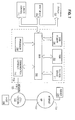
- Fig. 1 illustrates an example of a system that comprises a first sensor adapted to provide indications of a first type which relate to the vehicle's engine operational mode.
- Fig. 6A further illustrates functional units of an example idle time detection unit that may be used in an embodiment.
- the first sensor is the vehicle voltage sensing (VVS) device (110), which is connected to a power supply 102 of the vehicle (100).
- VVS 110 device may detect one or more voltage signature patterns in the vehicle's voltage output, which may indicate the vehicle's engine operational mode.
- the vehicle 100 may also comprise a second sensor, e.g. a GPS receiver (120), adapted to provide indications of a second type to enable determining whether the vehicle is moving or not.
- indication(s) of the second type are provided by one or more accelerometers which measure acceleration differences over the respective one or more axis by sampling the acceleration at a predetermined frequency e.g. 50Hz or 75Hz.
- the vehicle 100 further comprises a transmitter (130), which is adapted to transmit to a server computer (140) information that relates to indications of the first type (e.g. the ignition status from the VVS device) and information derived from the indications of the second type.
- the information received from the vehicle's transmitter (130) is analyzed (and optionally stored) at the server computer, and based on that analysis, unnecessary idling periods are identified.
- the information regarding the identified unnecessary idling periods is conveyed to the fleet manager/driver own personal computer (150), possibly via the internet.
- an idle time detection unit 602 may comprise VVS 110 coupled to power supply 102 and to processor 604, which is further coupled to GPS receiver 120 having a first antenna and transmitter 130 having a second antenna.
- Processor 604 is further coupled to storage 608 and idling period identifying logic 606, which may comprise one or more elements of hardware logic such as ASICs or FPGAs, or volatile or non-volatile memory storing instructions that the processor may load and execute.
- Idling period identifying logic 606 may be configured to implement the processes that are described herein when the logic is invoked or executed by processor 604.
- a process enable implementing the vehicle voltage level sensing approach for use in monitoring idling periods across multiple types of vehicles.
- the process may be implemented without the need to use additional hardware components and without adding the costs of a telematics device to the installation cost.
- Fig. 6B illustrates an example process of idle detection.
- the process detects a change in ignition status of the vehicle based on a change in vehicle voltage level.
- data representing the detected voltage level may be subject to filtering as indicated by filter 111 and as further described below.
- step 612 data is obtained indicating the movement or speed of the vehicle.
- step 614 a minimum idling threshold value is obtained for purposes of determining whether the data from steps 610, 612 actually represents an idling event.
- step 616 an idling event is detected based on the previously obtained parameter values. Particular ways of detecting idling events are described further herein.
- step 618 the process determines the type and duration of one or more idling events based on the previously obtained data. Particular types of idling events, and how to determine a duration or classification of idling events, is described further herein.
- step 620 one or more items of data representing idling periods, and optionally including idling rates, or various vehicle parameters, are stored. Also optionally, the stored data representing idling periods may be associated with data identifying a driver or vehicle.
- Fig. 6B provides an overview of an embodiment of a process of detecting an idling period of a motor vehicle based on changes in vehicle voltage levels.
- ignition events may be detected directly from the ignition switch using techniques described herein. Further, additional details for embodiments of the foregoing steps are now provided.
- current voltage levels of a vehicle's engine are measured and analyzed to enable determining the ignition status and/or to enable detecting changes in the ignition status.
- the process assumes that there are characteristic signatures or patterns of voltage level variation when a vehicle's engine is on, off, and while switching between on and off modes, and is adapted to detect such voltage signature patterns.
- the process may compensate for variations in the detected patterns across different vehicle types and their physical condition and individual vehicles. For example, old vehicles and/or an old battery may cause the voltage pattern to vary as compared to new ones. Embodiments may compensate for pattern variations over time occurring in individual vehicles.
- Fig. 2A provides a voltage level variation pattern.
- Fig. 2A illustrates three options to demonstrate that while vehicle may have a different voltage pattern, the difference in patterns does not influence the process, which takes into account the difference in the voltage.
- the voltage level variation pattern in Fig.2A consists of five sections (205,210,215,220 and 225), each section representing a different status of the engine. Before ignition the voltage level is at a constant standing voltage (section 205), then when the engine is turned on, there is a significant increase in the voltage over a certain period of time (section 210).
- the voltage remains relatively constant at a high value(section 215) until the engine is turned off (section 220), at which point the voltage drops over a certain period of time to a somewhat higher level than that of the standing voltage (section 225) before returning to the long-term engine off level. This latter transition is not shown in this Fig. 2A .
- voltage variation signature parameters enable high flexibility in modelling and compensating for behaviours of different vehicles, different batteries, and various operating conditions.
- Example parameters are demonstrated in Fig. 2B , in which the vertical axis illustrates voltage differences and the horizontal axis indicates time.
- Example initial default values are shown in Table 1.
- Table 1 Parameter name Reference numbers
- one or more of the following data may be captured and analysed or sent to the server computer: the ignition status (e.g. whether the engine is turned on or turned off), the timestamp (e.g. when was the ignition status changed), the location (e.g. GPS information which relates to the location at which the ignition status was changed), and the voltage level at the time when the ignition status was changed.
- the ignition status e.g. whether the engine is turned on or turned off
- the timestamp e.g. when was the ignition status changed
- the location e.g. GPS information which relates to the location at which the ignition status was changed
- the voltage level at the time when the ignition status was changed e.g. GPS information which relates to the location at which the ignition status was changed
- the voltage level sensing approach may also be used to enable detection of degradation in battery voltage performance. For example, if the battery is sufficiently drained, the voltage level variation signature may deviate from its normal signature, and/or there could be fluctuations in the voltage level when the engine is on. In an embodiment, such variations and fluctuations may be detected and responsive messages may be provided to the driver or to an operator of the server computer. A recommendation for replacing the battery should preferably not be automatically provided to the driver when such a situation is detected, because there could be other reasons for voltage levels degradation or that the voltage behaves aberrantly, for example: when the battery charging system or the vehicle's alternator is not working properly, loss of battery acid, etc.
- a filtering operation may be provided.
- a filtering processor calculates the average vehicle voltage during an ignition-on event (for example, the voltage reported in the ignition-on command) and takes into consideration real ignition-on events(for example, events that are known to be non-false events) at previous times, which are used as a reference, while not using false ignition-on events in the calculation.
- the calculated average vehicle voltage level during an ignition-on event is stored in memory.
- filter 111 represents filter processing.
- the filtering processor compares the present voltage level with the average level, and if the present voltage level is less than the average by a specified constant then the event is determined to be a false ignition-on.
- the false ignition on event may be marked in the database as a false ignition-on, to ensure that it is not used in the future for the average calculation.
- the specified constant may be a configurable parameter value, e.g. a starting value may be 0.25V or 0.5V). If the voltage level is higher than the average voltage level less the constant, then the event is a real ignition on event.
- the filtering processor is an integral part of the first sensor.
- the second indication may be obtained from a GPS receiver in the vehicle, and/or from one or more accelerometers (e.g. to obtain 3 dimensional samples), and/or by any other applicable sensor which is capable of providing indications of the vehicle movement.
- the following process serves as a non limiting example for using second indication type of data in order to detect one or more changes in the vehicle's operational status.
- the differences in the vehicle position is measured over the 3 axis, namely, ⁇ X, ⁇ Y, ⁇ Z (e.g. using samples obtained from measurements taken at a frequency in the range of 10Hz to 200Hz).
- the vehicle acceleration gradient ( ⁇ D) is then calculated, and the moving average (MA) and the moving standard deviation (SD) are derived therefrom.
- the MU was converted to Lognormal. In case that the status was defined as "OFF” (based on the information derived from the first indication) and the ON/OFF_index is now found to be greater than 10, the status will be changed to "ON", whereas, in case the status was defined as "ON” (based on information derived from the first indication) and the ON/OFF_index is found to be less than 0, the status will be changed to "OFF".
- the calculation of idling periods may be performed on data from a pre-defined time frame which occurred in the past.
- the term "driving session” includes the duration of time at which a vehicle is in motion, from the first motion detected till the vehicle is motionless for a continuous period of X minutes. However, if, during the driving session, the vehicle did not move during one or more periods, each extending for less than X minutes, these one or more periods will all be included in that driving session. For example, idling while stopping at traffic lights is included in the driving session. Once the vehicle did not move for X or more minutes, this motionless period will not be included within the same driving session, and a new driving session will start thereafter (when the vehicle starts moving once again).
- breaking period is defined as the duration of time at which a vehicle's engine is running while the vehicle is not moving, as long as that period is longer than a pre-defined value (e.g. Y minutes).
- X the driving session cut-off time
- Y the idling threshold duration is 5 minutes.
- a first driving session is from 12:00 until 15:30 and a second driving session is from 16:00 till 18:00.
- processing steps can distinguish between four types of idling periods:
- any idling period of more than 30 seconds is considered avoidable, because when the driver expects to stop for more than 30 seconds, the engine is expected to be turned off.
- turning the engine on and off successively is considered to be equal to about 10 seconds of engine running.
- the general rule for associating idling events (that are not entirely within a single driving session) with respective driving sessions is that an idling event should be associated with the driving session that immediately precedes it.
- This general rule assumes that each driver should be responsible for turning off the engine before turning over the vehicle to a next driver or before starting a new driving session.
- a benefit of the process recognizing the type of idling is for developing an appropriate procedure in order to prevent each particular type of idling. For example, idling that is associated with warming up the vehicle usually occurs in parking lots and may be avoided by better educating drivers.
- idling periods may also be associated with the respective driver, if information is available to identify the driver in the driving session. Associating a driving session with a particular driver may be performed using any available identification procedure.
- Embodiments provide a simple yet effective way to evaluate idling performance for an individual vehicle or individual driver as well as for a fleet or sub-fleet.
- evaluation is based on determining an idling rate, which is a fraction of the time during which the vehicle was idling, divided by the total time during which the engine was on.
- Determining idling rate enables managers to focus on drivers and/or vehicles that need their highest attention.
- processes allow categorisation of idling performance into green, yellow, and red levels.
- the definition of these levels i.e., the idling rate thresholds for each level
- green level idling could be defined as an idling rate below 0.5%
- yellow level idling as an idling rate between 0.5% and 1%
- red level idling as a rate of 1% or higher.
- the fleet manager may first focus on eliminating red level idling cases across the relevant drivers in his fleet and only then focus on moving drivers with yellow level idling performance into the green zone.
- idling periods are automatically associated with the particular vehicles that were idling.
- viewing idling event information per vehicle is not always sufficient.
- managers may wish to assess which drivers are responsible to the idling session(s), and often, which driving courses are associated with excessive idling periods. In other words, if it is found that a large number of drivers tend to leave their vehicles in idle mode when stopping at a certain place (e.g. a certain lay-by area), then the manager can instruct the drivers to take other routes whenever possible.
- the information regarding the idling periods is associated with a specific driver or specific driving course or specific location. This information provides managers better insight into idling behaviour across the fleet and allows them to refer to details about specific idling periods or driving course with poor idling performance, when they need to coach drivers.
- fleet managers when fleet managers log in to the company web site, they may be able to instantly assess the idling performance of their fleet via an idling performance level dashboard presentation.
- An example is illustrated in Fig.5 .
- fleet managers are able to drill down the presentation in order to view the performance of drivers or vehicles which are represented by the slice of the pie they click on. For example, clicking on the red slice will show idling performance for the red idlers.
- the idling results are reported to the driver, where such reporting can be made in addition to the reporting made to others such as the fleet manager, even though it can be done while using a different format, e.g. a more detailed format.
- the reporting to the driver can be made either when the driver logs on a device which is not part of the vehicle's systems such as a computer, a laptop, a smart phone, and the like, or the reporting/presentation of the idling results may be provided by the on-board system of the present invention to the driver, e.g. using a display means which constitutes part of the on board system in the vehicle.
- Embodiments provide for measuring idling duration in ways that overcome drawbacks of other approaches. For example, embodiments do not need a direct wire connection between a telematics device and the vehicle's ignition switch and do not need to use the ignition switch mechanism to determine if the engine is in an "on" or "off” position. A direct connection to the ignition switch is considered to constitute a violation of the vehicle warranty in some countries, and embodiments have the benefit of avoiding this issue. In other cases vehicles may not offer good locations where a connection to the ignition switch can be made. Still other vehicle models do not use a key switch, so that a direct connection cannot be made.
- Embodiments also avoid problems involved in using data retrieved from an Engine Computer Module (ECM).
- ECM Engine Computer Module
- a connection using a vehicle bus interface or protocol e.g., CANbus, FMS
- CANbus CANbus
- FMS Vehicle Bus Interface
- Using an ECM interface solely for detecting ignition status adds significantly to the cost of a system.
- Embodiments also provide numerous benefits to vehicle fleet managers operating under widely varying environments. Embodiments provide a flexible method to meet such varying needs in a novel and efficient manner.
- the techniques described herein are implemented by one or more special-purpose computing devices.
- the special-purpose computing devices may be hard-wired to perform the techniques, or may include digital electronic devices such as one or more application-specific integrated circuits (ASICs) or field programmable gate arrays (FPGAs) that are persistently programmed to perform the techniques, or may include one or more general purpose hardware processors programmed to perform the techniques pursuant to program instructions in firmware, memory, other storage, or a combination.
- ASICs application-specific integrated circuits
- FPGAs field programmable gate arrays
- Such special-purpose computing devices may also combine custom hard-wired logic, ASICs, or FPGAs with custom programming to accomplish the techniques.
- the special-purpose computing devices may be desktop computer systems, portable computer systems, handheld devices, networking devices or any other device that incorporates hard-wired and/or program logic to implement the techniques.
- FIG. 7 is a block diagram that illustrates a computer system 700 upon which an embodiment of the invention may be implemented.
- Computer system 700 includes a bus 702 or other communication mechanism for communicating information, and a hardware processor 704 coupled with bus 702 for processing information.
- Hardware processor 704 may be, for example, a general purpose microprocessor.
- Computer system 700 also includes a main memory 706, such as a random access memory (RAM) or other dynamic storage device, coupled to bus 702 for storing information and instructions to be executed by processor 704.
- Main memory 706 also may be used for storing temporary variables or other intermediate information during execution of instructions to be executed by processor 704.
- Such instructions when stored in non-transitory storage media accessible to processor 704, render computer system 700 into a special-purpose machine that is customized to perform the operations specified in the instructions.
- Computer system 700 further includes a read only memory (ROM) 708 or other static storage device coupled to bus 702 for storing static information and instructions for processor 704.
- ROM read only memory
- a storage device 710 such as a magnetic disk or optical disk, is provided and coupled to bus 702 for storing information and instructions.
- Computer system 700 may be coupled via bus 702 to a display 712, such as a cathode ray tube (CRT), for displaying information to a computer user.
- a display 712 such as a cathode ray tube (CRT)
- An input device 714 is coupled to bus 702 for communicating information and command selections to processor 704.
- cursor control 716 is Another type of user input device
- cursor control 716 such as a mouse, a trackball, or cursor direction keys for communicating direction information and command selections to processor 704 and for controlling cursor movement on display 712.
- This input device typically has two degrees of freedom in two axes, a first axis (e.g., x) and a second axis (e.g., y), that allows the device to specify positions in a plane.
- Computer system 700 may implement the techniques described herein using customized hard-wired logic, one or more ASICs or FPGAs, firmware and/or program logic which in combination with the computer system causes or programs computer system 700 to be a special-purpose machine. According to one embodiment, the techniques herein are performed by computer system 700 in response to processor 704 executing one or more sequences of one or more instructions contained in main memory 706. Such instructions may be read into main memory 706 from another storage medium, such as storage device 710. Execution of the sequences of instructions contained in main memory 706 causes processor 704 to perform the process steps described herein. In alternative embodiments, hard-wired circuitry may be used in place of or in combination with software instructions.
- Non-volatile media includes, for example, optical or magnetic disks, such as storage device 710.
- Volatile media includes dynamic memory, such as main memory 706.
- Common forms of storage media include, for example, a floppy disk, a flexible disk, hard disk, solid state drive, magnetic tape, or any other magnetic data storage medium, a CD-ROM, any other optical data storage medium, any physical medium with patterns of holes, a RAM, a PROM, and EPROM, a FLASH-EPROM, NVRAM, any other memory chip or cartridge.
- Storage media is distinct from but may be used in conjunction with transmission media.
- Transmission media participates in transferring information between storage media.
- transmission media includes coaxial cables, copper wire and fiber optics, including the wires that comprise bus 702.
- transmission media can also take the form of acoustic or light waves, such as those generated during radio-wave and infra-red data communications.
- Various forms of media may be involved in carrying one or more sequences of one or more instructions to processor 704 for execution.
- the instructions may initially be carried on a magnetic disk or solid state drive of a remote computer.
- the remote computer can load the instructions into its dynamic memory and send the instructions over a telephone line using a modem.
- a modem local to computer system 700 can receive the data on the telephone line and use an infra-red transmitter to convert the data to an infra-red signal.
- An infra-red detector can receive the data carried in the infra-red signal and appropriate circuitry can place the data on bus 702.
- Bus 702 carries the data to main memory 706, from which processor 704 retrieves and executes the instructions.
- the instructions received by main memory 706 may optionally be stored on storage device 710 either before or after execution by processor 704.
- Computer system 700 also includes a communication interface 718 coupled to bus 702.
- Communication interface 718 provides a two-way data communication coupling to a network link 720 that is connected to a local network 722.
- communication interface 718 may be an integrated services digital network (ISDN) card, cable modem, satellite modem, or a modem to provide a data communication connection to a corresponding type of telephone line.
- ISDN integrated services digital network
- communication interface 718 may be a local area network (LAN) card to provide a data communication connection to a compatible LAN.
- LAN local area network
- Wireless links may also be implemented.
- communication interface 718 sends and receives electrical, electromagnetic or optical signals that carry digital data streams representing various types of information.
- Network link 720 typically provides data communication through one or more networks to other data devices.
- network link 720 may provide a connection through local network 722 to a host computer 724 or to data equipment operated by an Internet Service Provider (ISP) 726.
- ISP 726 in turn provides data communication services through the world wide packet data communication network now commonly referred to as the "Internet" 728.
- Internet 728 uses electrical, electromagnetic or optical signals that carry digital data streams.
- the signals through the various networks and the signals on network link 720 and through communication interface 718, which carry the digital data to and from computer system 700, are example forms of transmission media.
- Computer system 700 can send messages and receive data, including program code, through the networks), network link 720 and communication interface 718.
- a server 730 might transmit a requested code for an application program through Internet 728, ISP 726, local network 722 and communication interface 718.
- the received code may be executed by processor 704 as it is received, and/or stored in storage device 710, or other non-volatile storage for later execution.
Landscapes
- Physics & Mathematics (AREA)
- General Physics & Mathematics (AREA)
- Combined Controls Of Internal Combustion Engines (AREA)
- Control Of Vehicle Engines Or Engines For Specific Uses (AREA)
Applications Claiming Priority (1)
| Application Number | Priority Date | Filing Date | Title |
|---|---|---|---|
| US13/071,389 US8805639B1 (en) | 2011-03-24 | 2011-03-24 | Idle detection for improving fuel consumption efficiency in a vehicle |
Publications (2)
| Publication Number | Publication Date |
|---|---|
| EP2503516A2 true EP2503516A2 (fr) | 2012-09-26 |
| EP2503516A3 EP2503516A3 (fr) | 2014-05-21 |
Family
ID=45952880
Family Applications (1)
| Application Number | Title | Priority Date | Filing Date |
|---|---|---|---|
| EP12160798.0A Withdrawn EP2503516A3 (fr) | 2011-03-24 | 2012-03-22 | Détection de ralenti pour améliorer l'efficacité de consommation de carburant dans un véhicule |
Country Status (3)
| Country | Link |
|---|---|
| US (1) | US8805639B1 (fr) |
| EP (1) | EP2503516A3 (fr) |
| IL (1) | IL218688A0 (fr) |
Cited By (3)
| Publication number | Priority date | Publication date | Assignee | Title |
|---|---|---|---|---|
| ITUA20164800A1 (it) * | 2016-06-30 | 2017-12-30 | Octo Telematics Spa | Procedimento per la stima della durata di un viaggio di un veicolo basato sulla determinazione dello stato del veicolo. |
| EP3798995A1 (fr) * | 2019-09-30 | 2021-03-31 | MOJ.IO Inc. | Système de véhicule doté d'un mécanisme d'arrêt véritable |
| EP4097689A4 (fr) * | 2020-01-31 | 2024-03-20 | Abax AS | Dispositif capteur destiné à analyser et à déterminer un mode de fonctionnement de véhicule, procédé d'analyse et de détermination d'un mode de fonctionnement de véhicule à l'aide d'un dispositif capteur et système d'analyse et de détermination d'un mode de fonctionnement de véhicule |
Families Citing this family (13)
| Publication number | Priority date | Publication date | Assignee | Title |
|---|---|---|---|---|
| JP5971175B2 (ja) * | 2012-12-13 | 2016-08-17 | トヨタ自動車株式会社 | 車載用太陽電池の制御装置 |
| US11279357B2 (en) * | 2013-12-25 | 2022-03-22 | Denso Corporation | Vehicle diagnosis system and method |
| CN107000687B (zh) | 2014-09-29 | 2019-09-13 | 莱尔德无线技术(上海)有限公司 | 远程信息处理装置 |
| CA2911305A1 (fr) * | 2014-11-04 | 2016-05-04 | Syncrude Canada Ltd. | Methode et systeme de gestion d'un parc d'equipements mobiles |
| IT201600068348A1 (it) * | 2016-07-01 | 2018-01-01 | Octo Telematics Spa | Procedimento per la determinazione dello stato di un veicolo mediante il rilevamento della tensione di batteria del veicolo. |
| US10650621B1 (en) | 2016-09-13 | 2020-05-12 | Iocurrents, Inc. | Interfacing with a vehicular controller area network |
| US10794747B2 (en) * | 2017-10-25 | 2020-10-06 | Ford Motor Company | Fleet management efficiency visualization |
| US10974728B2 (en) * | 2018-09-11 | 2021-04-13 | Lightmetrics Technologies Pvt. Ltd. | Methods and systems for facilitating drive related data for driver monitoring |
| US11736194B1 (en) | 2021-06-11 | 2023-08-22 | Nocell Technologies, LLC | System and method for determining a driver device from a plurality of network devices |
| US11785418B1 (en) | 2021-06-11 | 2023-10-10 | Nocell Technologies, LLC | System and method for determining network device handling |
| US11737049B1 (en) | 2021-06-11 | 2023-08-22 | Nocell Technologies, LLC | System and method for rapid release of policy implemented on a mobile device |
| US11676470B2 (en) | 2021-09-01 | 2023-06-13 | Nocell Technologies, LLC | Systems and methods for determining a wireless communications module of a network device has been disabled |
| EP4734082A1 (fr) * | 2024-10-23 | 2026-04-29 | GEOTAB Inc. | Systèmes et procédés d'identification de ralenti de véhicule |
Family Cites Families (9)
| Publication number | Priority date | Publication date | Assignee | Title |
|---|---|---|---|---|
| US4945759A (en) * | 1989-02-27 | 1990-08-07 | Gary F. Krofchalk | Vehicle performance monitoring system |
| US5619412A (en) * | 1994-10-19 | 1997-04-08 | Cummins Engine Company, Inc. | Remote control of engine idling time |
| US20100049398A1 (en) * | 2006-11-15 | 2010-02-25 | Radio Terminal Systems Pty Ltd. | Vehicle movement processing system |
| DE102008001304A1 (de) * | 2008-04-22 | 2009-10-29 | Robert Bosch Gmbh | Verfahren und Vorrichtung zur Detektion des Betriebszustandes eines Verbrennungsmotors |
| JP4954173B2 (ja) * | 2008-09-30 | 2012-06-13 | 本田技研工業株式会社 | 燃費向上のための運転操作を運転者に指導するための装置 |
| JP2010163943A (ja) * | 2009-01-14 | 2010-07-29 | Clarion Co Ltd | アイドリング判別装置、その制御方法及び制御プログラム |
| WO2010120512A1 (fr) * | 2009-03-31 | 2010-10-21 | Peoplenet, Inc. | Alarme dynamique d'arrêt de véhicule lourd en temps réel |
| IL201810A (en) * | 2009-10-29 | 2015-06-30 | Greenroad Driving Technologies Ltd | METHOD AND DEVICE FOR ASSESSING EFFECTIVE FUEL CONSUMPTION IN CAR |
| US20110288743A1 (en) * | 2010-05-18 | 2011-11-24 | Roger Neil Smith | System, apparatus and method for vehicle idling reduction |
-
2011
- 2011-03-24 US US13/071,389 patent/US8805639B1/en active Active
-
2012
- 2012-03-15 IL IL218688A patent/IL218688A0/en unknown
- 2012-03-22 EP EP12160798.0A patent/EP2503516A3/fr not_active Withdrawn
Non-Patent Citations (1)
| Title |
|---|
| None |
Cited By (8)
| Publication number | Priority date | Publication date | Assignee | Title |
|---|---|---|---|---|
| ITUA20164800A1 (it) * | 2016-06-30 | 2017-12-30 | Octo Telematics Spa | Procedimento per la stima della durata di un viaggio di un veicolo basato sulla determinazione dello stato del veicolo. |
| WO2018002891A1 (fr) * | 2016-06-30 | 2018-01-04 | Octo Telematics S.P.A. | Procédé d'estimation du temps de parcours d'un véhicule sur la base d'une détermination de l'état du véhicule |
| CN109952600A (zh) * | 2016-06-30 | 2019-06-28 | 奥克托信息技术股份公司 | 一种用于基于车辆的状态的确定来估计车辆的行驶时间的方法 |
| US10984613B2 (en) | 2016-06-30 | 2021-04-20 | Octo Telematics S.P.A. | Method for estimating the travel time of a vehicle based on the determination of the state of the vehicle |
| RU2760756C2 (ru) * | 2016-06-30 | 2021-11-30 | Окто Телематикс С.П.А. | Способ оценки времени в пути транспортного средства на основании определения состояния транспортного средства |
| EP3798995A1 (fr) * | 2019-09-30 | 2021-03-31 | MOJ.IO Inc. | Système de véhicule doté d'un mécanisme d'arrêt véritable |
| US11332153B2 (en) | 2019-09-30 | 2022-05-17 | Moj.Io, Inc. | Vehicle system with true off mechanism and method of operation thereof |
| EP4097689A4 (fr) * | 2020-01-31 | 2024-03-20 | Abax AS | Dispositif capteur destiné à analyser et à déterminer un mode de fonctionnement de véhicule, procédé d'analyse et de détermination d'un mode de fonctionnement de véhicule à l'aide d'un dispositif capteur et système d'analyse et de détermination d'un mode de fonctionnement de véhicule |
Also Published As
| Publication number | Publication date |
|---|---|
| IL218688A0 (en) | 2012-05-31 |
| US8805639B1 (en) | 2014-08-12 |
| EP2503516A3 (fr) | 2014-05-21 |
Similar Documents
| Publication | Publication Date | Title |
|---|---|---|
| US8805639B1 (en) | Idle detection for improving fuel consumption efficiency in a vehicle | |
| US7788003B2 (en) | Remote troubleshooting system | |
| US8850000B2 (en) | Trigger-based data collection system | |
| US9767624B2 (en) | Method and system for retrieving vehicular parameters from a vehicle data bus | |
| KR100764399B1 (ko) | 텔레매틱스 시스템의 차량 관리 시스템 및 그 방법 | |
| JP2004272375A (ja) | 遠隔故障予測システム | |
| CN118494510B (zh) | 一种主动安全驾驶辅助一体机云管理平台 | |
| CN118506474B (zh) | 一种基于物联网的新能源汽车数据实时采集方法 | |
| US20130311074A1 (en) | Ignition event generation using data from vehicle bus | |
| CN112937599A (zh) | 一种驾驶辅助性能监测系统及方法 | |
| CN114078324B (zh) | 车辆加塞行为检测方法、装置、路侧设备和存储介质 | |
| CN107478289A (zh) | 获取平均油耗的方法和装置 | |
| KR101747233B1 (ko) | 노면 상태 정보 제공 시스템, 및 방법 | |
| CN111307201A (zh) | 一种车辆状态监测系统及监测方法 | |
| CN111858140B (zh) | 污染物监控数据的校验方法、装置、服务器和介质 | |
| KR20160062259A (ko) | 차량 이상 상태를 관리하기 위한 방법, 시스템 및 컴퓨터 판독 가능한 기록매체 | |
| CN112319550A (zh) | 一种基于列车初上电的故障诊断方法、系统、装置及列车 | |
| CN114851985B (zh) | 车辆点火和熄火状态的识别方法、装置和车载设备 | |
| CN113727211B (zh) | 数据处理方法、装置、服务器、系统 | |
| CN113901399A (zh) | 一种汽车油耗检测的数据处理方法和装置 | |
| CN109263650A (zh) | 识别人工介入的方法、装置及交通工具 | |
| CN119438769A (zh) | 一种接地网腐蚀状态分析与展示方法、系统、介质及设备 | |
| CN110728839A (zh) | 车辆及其违法处罚方法与装置 | |
| CN106710028B (zh) | 用于测试无人驾驶车辆的唤醒耗时的方法和装置 | |
| CN112070382B (zh) | 基于大数据的车辆离线风控管理方法 |
Legal Events
| Date | Code | Title | Description |
|---|---|---|---|
| PUAI | Public reference made under article 153(3) epc to a published international application that has entered the european phase |
Free format text: ORIGINAL CODE: 0009012 |
|
| AK | Designated contracting states |
Kind code of ref document: A2 Designated state(s): AL AT BE BG CH CY CZ DE DK EE ES FI FR GB GR HR HU IE IS IT LI LT LU LV MC MK MT NL NO PL PT RO RS SE SI SK SM TR |
|
| AX | Request for extension of the european patent |
Extension state: BA ME |
|
| PUAL | Search report despatched |
Free format text: ORIGINAL CODE: 0009013 |
|
| AK | Designated contracting states |
Kind code of ref document: A3 Designated state(s): AL AT BE BG CH CY CZ DE DK EE ES FI FR GB GR HR HU IE IS IT LI LT LU LV MC MK MT NL NO PL PT RO RS SE SI SK SM TR |
|
| AX | Request for extension of the european patent |
Extension state: BA ME |
|
| RIC1 | Information provided on ipc code assigned before grant |
Ipc: G07C 5/08 20060101AFI20140414BHEP |
|
| STAA | Information on the status of an ep patent application or granted ep patent |
Free format text: STATUS: THE APPLICATION IS DEEMED TO BE WITHDRAWN |
|
| 18D | Application deemed to be withdrawn |
Effective date: 20141122 |