EP2502296B1 - Anordnung für eine brennstoffzelle sowie verfahren zu deren herstellung - Google Patents
Anordnung für eine brennstoffzelle sowie verfahren zu deren herstellung Download PDFInfo
- Publication number
- EP2502296B1 EP2502296B1 EP10784263.5A EP10784263A EP2502296B1 EP 2502296 B1 EP2502296 B1 EP 2502296B1 EP 10784263 A EP10784263 A EP 10784263A EP 2502296 B1 EP2502296 B1 EP 2502296B1
- Authority
- EP
- European Patent Office
- Prior art keywords
- electrolyte
- electrode
- layer
- adaptation layer
- arrangement according
- Prior art date
- Legal status (The legal status is an assumption and is not a legal conclusion. Google has not performed a legal analysis and makes no representation as to the accuracy of the status listed.)
- Active
Links
Images


Classifications
-
- H—ELECTRICITY
- H01—ELECTRIC ELEMENTS
- H01M—PROCESSES OR MEANS, e.g. BATTERIES, FOR THE DIRECT CONVERSION OF CHEMICAL ENERGY INTO ELECTRICAL ENERGY
- H01M4/00—Electrodes
- H01M4/86—Inert electrodes with catalytic activity, e.g. for fuel cells
- H01M4/8605—Porous electrodes
-
- H—ELECTRICITY
- H01—ELECTRIC ELEMENTS
- H01M—PROCESSES OR MEANS, e.g. BATTERIES, FOR THE DIRECT CONVERSION OF CHEMICAL ENERGY INTO ELECTRICAL ENERGY
- H01M8/00—Fuel cells; Manufacture thereof
- H01M8/02—Details
- H01M8/0202—Collectors; Separators, e.g. bipolar separators; Interconnectors
-
- H—ELECTRICITY
- H01—ELECTRIC ELEMENTS
- H01M—PROCESSES OR MEANS, e.g. BATTERIES, FOR THE DIRECT CONVERSION OF CHEMICAL ENERGY INTO ELECTRICAL ENERGY
- H01M4/00—Electrodes
- H01M4/86—Inert electrodes with catalytic activity, e.g. for fuel cells
- H01M4/8647—Inert electrodes with catalytic activity, e.g. for fuel cells consisting of more than one material, e.g. consisting of composites
- H01M4/8657—Inert electrodes with catalytic activity, e.g. for fuel cells consisting of more than one material, e.g. consisting of composites layered
-
- H—ELECTRICITY
- H01—ELECTRIC ELEMENTS
- H01M—PROCESSES OR MEANS, e.g. BATTERIES, FOR THE DIRECT CONVERSION OF CHEMICAL ENERGY INTO ELECTRICAL ENERGY
- H01M4/00—Electrodes
- H01M4/86—Inert electrodes with catalytic activity, e.g. for fuel cells
- H01M4/88—Processes of manufacture
- H01M4/8878—Treatment steps after deposition of the catalytic active composition or after shaping of the electrode being free-standing body
- H01M4/8892—Impregnation or coating of the catalyst layer, e.g. by an ionomer
-
- H—ELECTRICITY
- H01—ELECTRIC ELEMENTS
- H01M—PROCESSES OR MEANS, e.g. BATTERIES, FOR THE DIRECT CONVERSION OF CHEMICAL ENERGY INTO ELECTRICAL ENERGY
- H01M4/00—Electrodes
- H01M4/86—Inert electrodes with catalytic activity, e.g. for fuel cells
- H01M4/90—Selection of catalytic material
- H01M4/9016—Oxides, hydroxides or oxygenated metallic salts
- H01M4/9025—Oxides specially used in fuel cell operating at high temperature, e.g. SOFC
- H01M4/9033—Complex oxides, optionally doped, of the type M1MeO3, M1 being an alkaline earth metal or a rare earth, Me being a metal, e.g. perovskites
-
- H—ELECTRICITY
- H01—ELECTRIC ELEMENTS
- H01M—PROCESSES OR MEANS, e.g. BATTERIES, FOR THE DIRECT CONVERSION OF CHEMICAL ENERGY INTO ELECTRICAL ENERGY
- H01M8/00—Fuel cells; Manufacture thereof
- H01M8/10—Fuel cells with solid electrolytes
- H01M8/12—Fuel cells with solid electrolytes operating at high temperature, e.g. with stabilised ZrO2 electrolyte
- H01M8/1213—Fuel cells with solid electrolytes operating at high temperature, e.g. with stabilised ZrO2 electrolyte characterised by the electrode/electrolyte combination or the supporting material
-
- H—ELECTRICITY
- H01—ELECTRIC ELEMENTS
- H01M—PROCESSES OR MEANS, e.g. BATTERIES, FOR THE DIRECT CONVERSION OF CHEMICAL ENERGY INTO ELECTRICAL ENERGY
- H01M8/00—Fuel cells; Manufacture thereof
- H01M8/10—Fuel cells with solid electrolytes
- H01M8/12—Fuel cells with solid electrolytes operating at high temperature, e.g. with stabilised ZrO2 electrolyte
- H01M8/124—Fuel cells with solid electrolytes operating at high temperature, e.g. with stabilised ZrO2 electrolyte characterised by the process of manufacturing or by the material of the electrolyte
- H01M8/1246—Fuel cells with solid electrolytes operating at high temperature, e.g. with stabilised ZrO2 electrolyte characterised by the process of manufacturing or by the material of the electrolyte the electrolyte consisting of oxides
-
- H—ELECTRICITY
- H01—ELECTRIC ELEMENTS
- H01M—PROCESSES OR MEANS, e.g. BATTERIES, FOR THE DIRECT CONVERSION OF CHEMICAL ENERGY INTO ELECTRICAL ENERGY
- H01M8/00—Fuel cells; Manufacture thereof
- H01M8/10—Fuel cells with solid electrolytes
- H01M8/12—Fuel cells with solid electrolytes operating at high temperature, e.g. with stabilised ZrO2 electrolyte
- H01M8/124—Fuel cells with solid electrolytes operating at high temperature, e.g. with stabilised ZrO2 electrolyte characterised by the process of manufacturing or by the material of the electrolyte
- H01M8/1246—Fuel cells with solid electrolytes operating at high temperature, e.g. with stabilised ZrO2 electrolyte characterised by the process of manufacturing or by the material of the electrolyte the electrolyte consisting of oxides
- H01M8/1253—Fuel cells with solid electrolytes operating at high temperature, e.g. with stabilised ZrO2 electrolyte characterised by the process of manufacturing or by the material of the electrolyte the electrolyte consisting of oxides the electrolyte containing zirconium oxide
-
- H—ELECTRICITY
- H01—ELECTRIC ELEMENTS
- H01M—PROCESSES OR MEANS, e.g. BATTERIES, FOR THE DIRECT CONVERSION OF CHEMICAL ENERGY INTO ELECTRICAL ENERGY
- H01M8/00—Fuel cells; Manufacture thereof
- H01M8/10—Fuel cells with solid electrolytes
- H01M8/12—Fuel cells with solid electrolytes operating at high temperature, e.g. with stabilised ZrO2 electrolyte
- H01M8/124—Fuel cells with solid electrolytes operating at high temperature, e.g. with stabilised ZrO2 electrolyte characterised by the process of manufacturing or by the material of the electrolyte
- H01M8/1246—Fuel cells with solid electrolytes operating at high temperature, e.g. with stabilised ZrO2 electrolyte characterised by the process of manufacturing or by the material of the electrolyte the electrolyte consisting of oxides
- H01M8/126—Fuel cells with solid electrolytes operating at high temperature, e.g. with stabilised ZrO2 electrolyte characterised by the process of manufacturing or by the material of the electrolyte the electrolyte consisting of oxides the electrolyte containing cerium oxide
-
- Y—GENERAL TAGGING OF NEW TECHNOLOGICAL DEVELOPMENTS; GENERAL TAGGING OF CROSS-SECTIONAL TECHNOLOGIES SPANNING OVER SEVERAL SECTIONS OF THE IPC; TECHNICAL SUBJECTS COVERED BY FORMER USPC CROSS-REFERENCE ART COLLECTIONS [XRACs] AND DIGESTS
- Y02—TECHNOLOGIES OR APPLICATIONS FOR MITIGATION OR ADAPTATION AGAINST CLIMATE CHANGE
- Y02E—REDUCTION OF GREENHOUSE GAS [GHG] EMISSIONS, RELATED TO ENERGY GENERATION, TRANSMISSION OR DISTRIBUTION
- Y02E60/00—Enabling technologies; Technologies with a potential or indirect contribution to GHG emissions mitigation
- Y02E60/30—Hydrogen technology
- Y02E60/50—Fuel cells
-
- Y—GENERAL TAGGING OF NEW TECHNOLOGICAL DEVELOPMENTS; GENERAL TAGGING OF CROSS-SECTIONAL TECHNOLOGIES SPANNING OVER SEVERAL SECTIONS OF THE IPC; TECHNICAL SUBJECTS COVERED BY FORMER USPC CROSS-REFERENCE ART COLLECTIONS [XRACs] AND DIGESTS
- Y02—TECHNOLOGIES OR APPLICATIONS FOR MITIGATION OR ADAPTATION AGAINST CLIMATE CHANGE
- Y02P—CLIMATE CHANGE MITIGATION TECHNOLOGIES IN THE PRODUCTION OR PROCESSING OF GOODS
- Y02P70/00—Climate change mitigation technologies in the production process for final industrial or consumer products
- Y02P70/50—Manufacturing or production processes characterised by the final manufactured product
Definitions
- the invention relates to an arrangement for a fuel cell, with an electrode and an electrolyte, and to a method for producing the arrangement.
- a substrate is usually used, on which an electrolyte and the two electrodes (cathode and anode) are applied. For example, first the anode, then the electrolyte and finally the cathode are applied to the substrate.
- These components of the fuel cell, which are applied in layers, are electrochemically active cell layers and are also referred to as cathode-electrolyte-anode units (KEA units), as described, for example, in DE 103 43 652 A1 is known.
- the substrate acts as a mechanical support for the KEA unit and is, for example, ceramic or metallic.
- a metallic substrate for example a porous body consisting of sintered or pressed metal particles.
- Metallic substrates have the advantage that they enable a good thermal adaptation to a so-called interconnector and a technically simple electrical contact with this interconnector.
- the interconnector - also known as a bipolar plate or current collector - is arranged between two fuel cells and connects the individual fuel cells electrically in series.
- the interconnectors also mechanically support the fuel cells and separate and guide the reaction gases on the anode and cathode sides.
- the electrolyte is arranged between the anode and the cathode.
- the electrolyte has to meet several requirements. It must conduct oxygen ions and at the same time be insulating for electrons. In addition, the electrolyte must be gas-tight. In addition, an undesirable chemical reaction between the electrolyte and an adjacent electrode must be avoided.
- DE 10 2007 015 358 A1 a multilayer structure of an electrolyte from at least three layers is provided.
- a method for producing a thin electrolyte layer on a porous electrode in which a suspension comprising electrode material is first poured onto an electrode and dried (intermediate electrode layer), the size of the solids content of this suspension being selected such that after drying, the intermediate electrode layer is one has an average pore size that is smaller than the average pore size of the electrode layer. A further suspension comprising electrolyte material is then poured onto this intermediate electrode layer and dried.
- the invention has for its object to provide an arrangement that simplifies the construction of a fuel cell.
- the invention is also based on the object of providing a method for producing such an arrangement.
- an adaptation layer is provided in the arrangement between an electrode and the electrolyte.
- This adaptation layer brings about a good connection or adaptation of the electrolyte to the electrode. Furthermore, it supports a flat structure of the arrangement or the fuel cell if a metallic porous carrier substrate is provided for the electrodes and the electrolyte.
- metallic porous carrier substrates are mechanically more stable in comparison to ceramic carrier substrates and can be provided with a particularly small substrate thickness.
- the gas-tight electrolyte should be made as thin as possible. This requires the smallest possible roughness on the electrode surface associated with the electrolyte (eg anode surface). Accordingly, the electrode material must be applied to the carrier substrate in such a way that this desired low surface roughness is achieved on the electrode. This is opposed by the relatively large surface roughness of the metallic porous carrier substrate.
- the average pore size of the adaptation layer is smaller than the average pore size of the electrode. This ratio of the average pore sizes applies at least to the near-surface layer regions of the surfaces of the electrolyte facing Electrode layer and adaptation layer. This ratio preferably applies to the entire layer thickness of the electrode and the adaptation layer.
- a surface structure is made available in the arrangement which technically simplifies the application of a gas-tight thin-layer electrolyte.
- PVD physical vapor deposition
- a single thin electrolyte layer is therefore sufficient for the proper functioning of the fuel cell, which simplifies the manufacture of the fuel cell.
- the internal cell resistance of the fuel cell is significantly reduced compared to fuel cells with plasma-sprayed electrolytes, which require a layer thickness of approx. 40 ⁇ m for sufficient gas tightness, which means that higher power yields can be achieved.
- the adaptation layer can be selected in terms of material and structure, in particular pore structure, such that an electrolyte can always be applied to an electrode (anode or cathode) with the adaptation layer interposed.
- the adaptation layer is used in the case of reduced anode layer structures on which a gas-tight electrolyte layer cannot be applied directly.
- reduced anode layer structures arise, for example, in connection with metallic substrates.
- These substrates are preferably produced by powder metallurgy and in particular are provided in the form of plates.
- a central area of this substrate is porous and serves as a mechanical support for the electrochemically active cell layers.
- These cell layers can be, for example, by wet chemical coating (such as screen printing or wet powder spraying) with subsequent sintering or by thermal spraying processes (such as plasma spraying or high-speed flame spraying) getting produced.
- Metallic carrier substrates have the advantage over ceramic carrier substrates that they are thermally more resilient and more redox-stable during operation.
- the anode structure applied to the carrier substrate is sintered in a reduced atmosphere, so that the anode structure is in a reduced, porous form.
- the nickel oxide contained in the anode structure before sintering is reduced during the sintering, which leads to a coarsening of its grain size due to the high sintering activity, and pores with relatively large diameters (for example 2 ⁇ m) are formed.
- Such a surface structure of the anode is often not suitable for applying a gas-tight thin-film electrolyte directly to the anode structure.
- the desired gas tightness of the electrolyte is not guaranteed if it is to be applied to the anode structure by means of gas phase deposition (eg PVD process). This problem is solved by means of the adaptation layer described above.
- the roughness can be used to physically characterize a surface.
- the primary profile was measured optically (confocal laser topograph) and the filtered roughness profile and the roughness values were calculated in accordance with DIN EN ISO 11562 and 4287.
- the lengths of the sensing distance ( I t ), measuring distances ( I n ) and individual measuring distances ( I r ) were selected in accordance with DIN EN ISO 4288.
- the arithmetic mean roughness value R a indicates the arithmetic mean of the amounts of all profile values of a roughness profile.
- the quadratic mean roughness value R q (also referred to as mean surface roughness R q ) is the quadratic mean value of all profile values and weights outliers more than the arithmetic mean roughness value R a .
- the average roughness depth R z is defined according to DIN EN ISO 4287 as the arithmetic mean of the individual roughness depths of all individual measuring sections.
- a Single roughness means the distance between the highest peak and the deepest groove in a single measurement section. The entire measuring section is divided into 5 consecutive segments of the same size (individual measuring sections). Since the R z value is determined by the deepest valleys and highest peaks, this is particularly dependent on the measurement method used. In contrast to the optical method used here, it must be taken into account, for example, with mechanical stylus methods that depending on the tip geometry used, not all of the pointed valleys can be captured.
- bumps of this wavelength do not yet play a decisive role in the quality and tightness of the layer, but bumps with a significantly smaller wavelength.
- micro-roughness is used in this invention, which is based on a limit wavelength of 0.15 mm for otherwise identical total measuring sections.
- These micro roughnesses were measured accordingly R a ⁇ .
- the average pore size and the sintered grain size can be used as further characteristic parameters for describing the properties of a sintered layer. Both dimensions can be determined for any structure, including open pores, using the line-cutting method on scanning electron microscope images of cross sections.
- the individual phases are first of all shown in the images via contrast differences, grain shape or element analysis (e.g. energy dispersive X-ray spectroscopy, EDX) marked accordingly, then statistically drawn straight lines and the intersections at the transitions between the different phases marked.
- the average value of all lengths of the route sections thus created, which lie in one phase reflects the average cutting line length for this phase (e.g. pores).
- This average cutting line length is converted into the actual grain size or pore size by multiplication with a corresponding geometry factor.
- the value 1.68 and the value 1.56 [2] were used as the geometry factor, assuming the commonly used model of pores around tetrakaidecahedral grains according to reference [1]. If sintered grain sizes are also spoken of in this invention, this means the morphologically readable grain size from the structure. The samples were not etched before analysis.
- the maximum pore size was determined from a series of scanning electron micrographs from the largest inner diameters of all pores.
- the inner diameter of a pore denotes the length of the largest straight section that runs inside the pore.
- a suitable magnification must be observed in the microscopic images.
- the pore or grain size to be determined still has to be resolved and at the same time completely captured by the image section.
- the adaptation layer allows the electrolyte to be applied directly, so that in the sense of a simplified, space-saving construction of the fuel cell, additional intermediate layers between the electrolyte and the adaptation layer can be dispensed with.
- the average pore size of the adaptation layer is preferably at most half the size of the average pore size of the electrode. It is also possible to use a gas-tight thin-layer electrolyte ( ⁇ 10 ⁇ m) via PVD, here to be applied in particular by means of electron beam evaporation or sputter processes, or sol-gel technologies.
- the average pore size of the pores (at least in the layer region close to the layer surface facing the electrolyte) of the adaptation layer is preferably at most 500 nm. This supports a homogeneous growth of the electrolyte material (e.g. as a PVD layer) on the adaptation layer. With medium pore sizes above 500 nm there is a risk that the pores can no longer be sealed gas-tight with a thin electrolyte layer.
- the average pore size of the adaptation layer (at least in its near-surface layer area of the layer surface facing the electrolyte) is at most 350 nm, more preferably at most 250 nm.
- the adaptation layer preferably has, as the average surface roughness, a square mean roughness value R q of less than 2.5 ⁇ m, preferably at most 1.5 ⁇ m, more preferably at most 1.0 ⁇ m.
- a quadratic mean roughness value R q above 2.5 ⁇ m leads to potential leaks in the subsequent thin-film electrolyte. For example, intercolumnar gaps can arise when a subsequent PVD layer grows.
- higher roughness values mean that the wetting of the profile tips can no longer be guaranteed or the critical layer thickness in the profile valleys is exceeded, which leads to cracks in the thin-film electrolyte.
- a diffusion barrier is preferably arranged between the carrier substrate and an electrode, in particular the anode. It can prevent metallic interdiffusion and other reactions between the substrate and the electrode and thus contributes to long-term stability and a longer service life of the arrangement.
- SOFCs Solid Oxide Fuel Cell
- the electrolyte applied to the adaptation layer preferably has a layer thickness of 0.2 to 10 ⁇ m.
- the required gas tightness of the electrolyte layer is not guaranteed below a layer thickness of 0.2 ⁇ m.
- the increase in the layer thickness of the electrolyte is accompanied by a significant increase in the ohmic resistance and consequently by a reduced output of the fuel cell, so that a maximum layer thickness of 10 ⁇ m is preferred.
- the arrangement with the electrolyte and the adaptation layer is preferably used in a fuel cell, in particular in a high-temperature fuel cell.
- High-temperature fuel cells include oxide-ceramic fuel cells - also called SOFC. Due to its high electrical efficiency and the possible use of the waste heat generated at high operating temperatures, the SOFC is particularly suitable as a fuel cell.
- a suitable material for the metallic substrate is, for example, a ferritic FeCrMx alloy and a chromium-based alloy.
- the FeCrMx alloy regularly has chromium contents between 16 and 30% by weight and additionally at least one alloying element in a proportion of 0.01 to 2% by weight, which is selected from the group of rare earth metals or their oxides, e.g. B. Y, Y 2 O 3 , Sc, Sc 2 O 3 , or from the group Ti, Al, Mn, Mo or Co.
- ferritic steels examples include Ferrochrom (1.4742), CrAl20 5 (1.4767) and CroFer 22 APU from Thyssen Krupp, FeCrAlY from Technetics, ZMG 232 from Hitachi Metals, SUS 430 HA and SUS 430 Na from Nippon Steel and all ODS iron-based alloys of the ITM class from Plansee, such as ITM Fe-26Cr- (Mo, Ti, Y 2 O 3 )
- a chromium-based alloy that is to say with a chromium content of more than 65% by weight, for example Cr5FeIY or Cr5FeIY 2 O 3 , can also be used as the porous metallic substrate.
- the diffusion barrier layer consists, for example, of lanthanum strontium manganite (LSM), lanthanum strontium chromite (LSCR) or gadolinium oxide-doped cerium oxide (CGO).
- LSM lanthanum strontium manganite
- LSCR lanthanum strontium chromite
- CGO gadolinium oxide-doped cerium oxide
- the anode can be constructed as a multilayer composite or as a single layer. The same applies in principle to the cathode.
- First a first electrode is applied to the substrate, e.g. by means of a wet chemical process.
- a porous adaptation layer is applied to the electrode.
- the electrolyte can be applied to the adaptation layer in a gas-tight manner with little outlay on the process, since the average pore size of the adaptation layer is smaller than the average pore size of the electrode.
- a suitable layer thickness of the adaptation layer is advantageously achieved by applying it to the electrode by wet chemistry. This can for example by means of screen printing, dip coating or slip casting.
- the adaptation layer can also be applied in multiple layers.
- the material of the adaptation layer is repeatedly applied in several process steps.
- the electrode is repeatedly dip-coated and dried between individual coating processes.
- the multi-layer application supports a homogeneous adaptation layer. Irregular surface courses of the adaptation layer are avoided. This in turn creates advantageous physical conditions for the application of the electrolyte material to the adaptation layer.
- the adaptation layer consists of a pure ion-conducting material, that is, an electron-non-conducting material.
- the required electrical insulation between the two electrodes (anode and cathode) is thus already ensured by the adaptation layer. Additional electronic insulation layers can be omitted, so that the structure of the fuel cell is simplified.
- the gas-tight electrolyte can therefore also consist of a layer that - e.g. under operating conditions of the fuel cell - has a significant electronic conductivity. This is e.g. for an electrolyte made of gadolinium oxide-doped cerium oxide (CGO) at higher temperatures (> 650 ° C).
- CGO gadolinium oxide-doped cerium oxide
- Doped zirconium oxide is used as the material for the electronically non-conductive adaptation layer. At least one oxide of the doping elements from the group Y, Sc, Al, Sr, Ca is suitable as the doping.
- the adaptation layer can be designed as a YSZ layer (yttrium oxide-stabilized zirconium dioxide).
- an ion and electron conducting material is used for the adaptation layer.
- Doped cerium oxide is particularly suitable for this.
- the adaptation layer can be designed as a CGO layer. In this case, the electrical insulation between the two electrodes should be taken over by the gas-tight electrolyte layer.
- An oxide ceramic for example doped zirconium oxide, is preferably used as the material for the electronically non-conductive thin-film electrolyte. At least one oxide of the doping elements from the group Y, Sc, Al, Sr, Ca is suitable as doping.
- the thin-layer electrolyte can be designed as a YSZ layer (yttrium oxide-stabilized zirconium dioxide).
- YSZ layer yttrium oxide-stabilized zirconium dioxide
- the aforementioned materials for the adaptation layer can also be used for the electrolyte.
- cathodes can also be applied directly to this electrolyte, which are designed as a Sr component reacting with ZrO 2 , for example lanthanum strontium cobalt ferrite (LSCF) or lanthanum strontium cobaltite ( LSC).
- LSCF lanthanum strontium cobalt ferrite
- LSC lanthanum strontium cobaltite
- the adaptation layer applied to the electrode is preferably sintered.
- the sintering temperature is in particular 950 ° C to 1300 ° C, so that no undesired structural changes in the adaptation layer can be expected during operation of the fuel cell (e.g. SOFC, up to 850 ° C).
- a powder with an average grain size of 30 to 500 nm, in particular 150 nm is preferably used for the adaptation layer. This also prevents excessive infiltration into a porous electrode layer (e.g. anode layer).
- the adaptation layer offers the possibility of producing a stable and gas-tight electrolyte layer structure by means of gas phase deposition.
- This process also allows particularly thin electrolyte layers.
- an electrolyte with a layer thickness of 0.2 to 10 ⁇ m, preferably 1 to 3 ⁇ m, more preferably 1 to 2 ⁇ m, can be deposited on the adaptation layer.
- the PVD process physical vapor deposition
- the electrolyte can be applied using sol-gel technology.
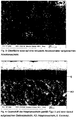
- the Figure 1 shows the surface of a reduced anode structure (Ni / 8YSZ), which is applied to a porous metallic substrate (ITM), not shown here.
- ITM porous metallic substrate
- FIG 2 shows a cross section of the anode structure coated with an electrolyte Figure 1 ,
- the multilayer electrolyte was applied to the anode structure by means of a PVD coating and consists of a CGO layer (E1), an 8YSZ layer (E2) and a further CGO layer (E3).
- E1 CGO layer
- E2 8YSZ layer
- E3 CGO layer
- the Figure 3 shows the surface structure of the adaptation layer applied to an anode structure. This is clearly recognizable in comparison with the anode structure Figure 1 significantly reduced pore size of the pores of the adaptation layer.
- the Figure 4 shows a cross section of the adaptation layer according to Figure 3 and an electrolyte applied thereon.
- the electrolyte is formed as a single layer of CGO and was applied using a PVD process. The growth of the electrolyte layer is undisturbed and homogeneous, so that the required gas tightness of the electrolyte is achieved.
- the roughness of the surface of this anode structure should be less than 3 ⁇ m, preferably less than 2 ⁇ m, for the square micro-center roughness value for the square mean roughness value R q R q ⁇ less than 1 ⁇ m, preferably less than 0.6 ⁇ m, and for the mean roughness depth R z less than 10 ⁇ m, preferably less than 6 ⁇ m, and for the mean microroughness depth R z ⁇ less than 4 microns, preferably less than 2 microns.
- the laser topograph CT200 (Cybertechnolgies GmbH, Ingolstadt) with a confocal laser sensor LT9010 was used to determine the roughness (measuring spot size approx. 2 ⁇ m, vertical resolution 10nm).
- At least three scanning electron micrographs of cross sections of the layers were evaluated for each parameter for the grain and pore sizes of the sintered structure determined using the line cutting method. 500-1,000 lines were drawn per image. With a number of pixels of the raster electronic recordings of 1024x768 pixels, a total section of the width of 5 to 15 ⁇ m was chosen for the adaptation layer.
- An 8YSZ powder with an average dispersible primary particle size of 150 nm and a specific surface area of 13 m 2 / g was used for the adaptation layer (TZ-8Y, Tosoh Corp., Japan).
- An immersion suspension was mixed with grinding balls with a diameter of 5 and 10 mm and homogenized on a roller bench for 48 hours, consisting of 67.2% by weight of solvent DBE (Dibasic ester, Lemro Chemical Products Michael Mrozyk KG, Grevenbroich), 30.5% by weight.
- % 8YSZ powder (TZ-8Y) and 2.3% by weight of ethyl cellulose as a binder (Fluka, 3-5.5 mPa s, Sigma-Aldrich Chemie GmbH, Kunststoff).
- the carrier substrates with the anode structure applied to them were immersed vertically in the suspension and, after a drying step in an H 2 atmosphere, sintered at 1200 ° C. for 3 hours.
- an adaptation layer thickness of 10 to 20 ⁇ m was obtained.
- the adaptation layer applied in this way had a square mean roughness value R q of 1.2 ⁇ m and an average roughness depth R z of 5.8 ⁇ m.
- the square micro-center roughness R q ⁇ showed a value of 0.21 ⁇ m and the average microroughness R z ⁇ showed a value of 0.67 ⁇ m.
- the gas tightness of this electrolyte was determined by means of a He leak test to be 3.4 ⁇ 10 -3 (hPa dm 3 ) / (s cm 2 ) for a pressure difference of 1000 hPa. This value corresponds to common anode-supported fuel cells in the reduced state.
Landscapes
- Chemical & Material Sciences (AREA)
- Engineering & Computer Science (AREA)
- Manufacturing & Machinery (AREA)
- Electrochemistry (AREA)
- General Chemical & Material Sciences (AREA)
- Chemical Kinetics & Catalysis (AREA)
- Life Sciences & Earth Sciences (AREA)
- Sustainable Development (AREA)
- Sustainable Energy (AREA)
- Materials Engineering (AREA)
- Composite Materials (AREA)
- Inert Electrodes (AREA)
- Fuel Cell (AREA)
Description
- Die Erfindung betrifft eine Anordnung für eine Brennstoffzelle, mit einer Elektrode und einem Elektrolyt sowie ein Verfahren zur Herstellung der Anordnung.
- Bei der Herstellung von Hochtemperatur-Brennstoffzellen wird üblicherweise ein Substrat verwendet, auf dem ein Elektrolyt und die beiden Elektroden (Kathode und Anode) aufgebracht sind. Beispielsweise werden auf das Substrat zunächst die Anode, danach der Elektrolyt und schließlich die Kathode aufgebracht. Diese schichtartig aufgebrachten Bestandteile der Brennstoffzelle sind elektrochemisch aktive Zellschichten und werden auch als Kathoden-Elektrolyt-Anoden-Einheit (KEA-Einheit) bezeichnet, wie dies z.B. aus
DE 103 43 652 A1 bekannt ist. Das Substrat wirkt als mechanischer Träger für die KEA-Einheit und ist z.B. keramisch oder metallisch ausgebildet.
InDE 103 43 652 A1 ist ein metallisches Substrat vorgesehen, z.B. ein aus gesinterten oder gepressten Metallpartikeln bestehender poröser Körper. Metallische Substrate haben den Vorteil, dass sie eine gute thermische Anpassung an einen sogenannten Interkonnektor und eine technisch einfache elektrische Kontaktierung mit diesem Interkonnektor ermöglichen. Der Interkonnektor - auch als bipolare Platte oder Stromsammler bezeichnet - ist zwischen zwei Brennstoffzellen angeordnet und verbindet die einzelnen Brennstoffzellen elektrisch in Serie. Außerdem stützen die Interkonnektoren die Brennstoffzellen mechanisch und sorgen für eine Trennung und Führung der Reaktionsgase auf der Anoden- und Kathodenseite. - Zwischen der Anode und der Kathode ist der Elektrolyt angeordnet. Der Elektrolyt muss mehrere Anforderungen erfüllen. Er muss Sauerstoffionen leiten und gleichzeitig für Elektronen isolierend sein. Außerdem muss der Elektrolyt gasdicht sein. Darüber hinaus muss eine unerwünschte chemische Reaktion zwischen dem Elektrolyt und einer angrenzenden Elektrode vermieden werden. Um diesen Anforderungen gerecht zu werden, ist in
DE 10 2007 015 358 A1 ein mehrschichtiger Aufbau eines Elektrolyts aus mindestens drei Schichten vorgesehen. - Aus
DE 196 26 342 A1 ist ein Verfahren zur Herstellung einer dünnen Elektrolytschicht auf einer porösen Elektrode bekannt, bei dem zunächst eine Suspension umfassend Elektrodenmaterial auf eine Elektrode gegossen und getrocknet wird (Elektrodenzwischenschicht), wobei die Größe der Feststoffanteile dieser Suspension derart gewählt wird, dass nach dem Trocknen die Elektrodenzwischenschicht eine mittlere Porengröße aufweist, die kleiner ist, als die mittlere Porengröße der Elektrodenschicht. Anschließend wird eine weitere Suspension umfassend Elektrolytmaterial auf diese Elektrodenzwischenschicht gegossen und getrocknet. - Der Erfindung liegt die Aufgabe zugrunde, eine Anordnung bereitzustellen, die den Aufbau einer Brennstoffzelle vereinfacht. Weiterhin liegt der Erfindung die Aufgabe zugrunde, ein Verfahren zur Herstellung einer solchen Anordnung bereitzustellen.
- Diese Aufgabe wird durch eine Anordnung mit der Merkmalskombination des Anspruches 1 sowie durch ein Verfahren zur Herstellung der Anordnung mit der Merkmalskombination des Anspruches 13 gelöst. Erfindungsgemäß ist in der Anordnung zwischen einer Elektrode und dem Elektrolyt eine Adaptionsschicht vorgesehen. Diese Adaptionsschicht bewirkt eine gute Anbindung bzw. Adaption des Elektrolyts an die Elektrode. Weiterhin unterstützt sie einen flachen Aufbau der Anordnung bzw. der Brennstoffzelle, wenn ein metallisches poröses Trägersubstrat für die Elektroden und den Elektrolyt bereitgestellt wird.
- Einerseits sind metallische poröse Trägersubstrate im Vergleich zu keramischen Trägersubstraten mechanisch stabiler und können mit einer besonders geringen Substratdicke bereitgestellt werden. Andererseits soll der gasdichte Elektrolyt möglichst dünn ausgebildet sein. Dies setzt eine möglichst kleine Rauhigkeit an der dem Elektrolyt zugeordneten Elektroden-Oberfläche (z.B. Anoden-Oberfläche) voraus. Entsprechend muss das Elektroden-Material derart auf das Trägersubstrat aufgebracht werden, dass diese gewünschte geringe Oberflächen-Rauhigkeit an der Elektrode erzielt wird. Dem steht die verhältnismäßig große Oberflächen-Rauhigkeit des metallischen porösen Trägersubstrates entgegen. Das Erzielen der gewünschten geringen Oberflächen-Rauhigkeit an der Elektrode wird noch zusätzlich erschwert, wenn die Elektrode (insbesondere als Anode) bei reduzierten Prozessbedingungen mittels Sintern auf dem Trägersubstrat hergestellt wird, weil hierdurch eine vergröberte Rauhigkeit an der Elektroden-Oberfläche entsteht. Diese Probleme werden erfindungsgemäß gelöst, indem die mittlere Porengröße der Adaptionsschicht kleiner ist als die mittlere Porengröße der Elektrode. Dieses Verhältnis der mittleren Porengrößen gilt zumindest für die oberflächennahen Schichtbereiche der dem Elektrolyt zugewandten Oberflächen von Elektrodenschicht und Adaptionsschicht. Vorzugsweise gilt dieses Verhältnis für die gesamte Schichtdicke von Elektrode und Adaptionsschicht. Mit Hilfe des vorgenannten Verhältnisses der mittleren Porengröße wird in der Anordnung eine Oberflächenstruktur zur Verfügung gestellt, die das Aufbringen eines gasdichten Dünnschichtelektrolyten technisch vereinfacht. Insbesondere ist es mittels der Adaptionsschicht möglich, besonders dünne Elektrolyt-Schichten (< 10 µm) - beispielsweise mittels physikalischer Gasphasenabscheidung (PVD = physical vapour deposition), hierbei insbesondere über Elektronenstrahlverdampfen bzw. Sputter-Prozesse, oder Sol-Gel-Verfahren - gasdicht aufzubringen. Abhängig vom Material der Adaptionsschicht ist deshalb eine einzige dünne Elektrolytschicht für die ordnungsgemäße Funktionsweise der Brennstoffzelle ausreichend, was die Herstellung der Brennstoffzelle vereinfacht. Zudem wird der innere Zellwiderstand der Brennstoffzelle im Vergleich zu Brennstoffzellen mit plasmagespritzten Elektrolyten, die für eine ausreichende Gasdichtheit eine Schichtdicke von ca. 40 µm benötigen, signifikant reduziert, wodurch höhere Leistungsausbeuten erzielt werden können.
- Die Adaptionsschicht kann hinsichtlich Material und Struktur, insbesondere Porenstruktur, derart ausgewählt werden, dass ein Elektrolyt unter Zwischenlage der Adaptionsschicht immer auf eine Elektrode (Anode oder Kathode) aufgebracht werden kann.
- Die Adaptionsschicht wird erfindungsgemäß bei reduzierten Anodenschichtstrukturen eingesetzt, auf denen ein direktes Aufbringen einer gasdichten Elektrolyt-Schicht nicht möglich ist. Derartige reduzierte Anodenschichtstrukturen ergeben sich z.B. im Zusammenhang mit metallischen Substraten. Diese Substrate werden vorzugsweise pulvermetallurgisch hergestellt und dabei insbesondere plattenartig bereitgestellt. Ein zentraler Bereich dieses Substrates ist porös und dient als mechanischer Träger für die elektrochemisch aktiven Zellschichten. Diese Zellschichten können z.B. durch nasschemische Beschichtung (wie Siebdruck oder Nasspulverspritzen) mit anschließender Sinterung oder durch thermische Spritzverfahren (wie Plasmaspritzen oder Hochgeschwindigkeitsflammspritzen) hergestellt werden. Metallische Trägersubstrate haben gegenüber keramischen Trägersubstraten den Vorteil, dass sie thermisch belastbarer und während des Betriebes redox-stabiler sind. Allerdings muss eine Oxidation des Trägersubstrates während der Herstellung verhindert werden, da eine Bildung von Metalloxid Volumenänderungen im Trägersubstrat bewirken würde, die ein defektfreies Aufbringen der Elektroden und des Elektrolyt auf das Trägersubstrat gefährden würde. Außerdem erhöht sich bei dem oxidierenden Trägersubstrat dessen elektrischer Widerstand, was sich nachteilig auf die spätere Zellleistung auswirken würde. Deshalb wird eine Sinterung der auf das Trägersubstrat aufgebrachten Anodenstruktur in reduzierter Atmosphäre durchgeführt, so dass die Anodenstruktur in reduzierter, poröser Form vorliegt. Das vor der Sinterung in der Anodenstruktur enthaltene Nickeloxid wird während der Sinterung reduziert, was aufgrund der hohen Sinteraktivität zu einer Vergröberung ihrer Korngröße führt, und es entstehen Poren mit verhältnismäßig großen Durchmessern (z.B. 2 µm). Eine derartige Oberflächenstruktur der Anode ist oftmals nicht dazu geeignet, einen gasdichten Dünnschichtelektrolyten direkt auf die Anodenstruktur aufzubringen. Insbesondere ist die gewünschte Gasdichtheit des Elektrolyt nicht gewährleistet, wenn er mittels Gasphasenabscheidung (z.B. PVD-Verfahren) auf die Anodenstruktur aufgebracht werden soll. Dieses Problem wird mittels der oben beschriebenen Adaptionsschicht gelöst.
- Zur physikalischen Charakterisierung einer Oberfläche kann die Rauhigkeit herangezogen werden. Das Primärprofil wurde optisch vermessen (konfokaler Lasertopograph) und das gefilterte Rauheitsprofil und die Rauwerte gemäß DIN EN ISO 11562 und 4287 berechnet. Die Längen der Taststrecke (It ), Messstrecken (In ) und- Einzelmessstrecken (Ir ) wurden gemäß DIN EN ISO 4288 gewählt. Nach DIN EN ISO 4287 gibt der arithmetische Mittenrauwert Ra den arithmetischen Mittelwert der Beträge aller Profilwerte eines Rauheitsprofils an. Der quadratische Mittenrauwert Rq (auch als mittlere Oberflächenrauhigkeit Rq bezeichnet) ist der quadratische Mittelwert aller Profilwerte und wichtet Ausreißer stärker als der arithmetische Mittenrauwert Ra . Die gemittelte Rautiefe Rz ist gemäß DIN EN ISO 4287 als das arithmetische Mittel der Einzelrautiefen aller Einzelmessstrecken definiert. Eine Einzelrautiefe bedeutet dabei den Abstand zwischen der höchsten Spitze und der tiefsten Riefe in einer Einzelmessstrecke. Die gesamte Messtrecke wird dabei in 5 gleichgroße, aufeinanderfolgende Segmente (Einzelmessstrecken) unterteilt. Da der Rz -Wert von den tiefsten Tälern und höchsten Spitzen bestimmt wird, ist dieser besonders von dem verwendeten Messverfahren abhängig. Im Gegensatz zu dem hier verwendeten optischen Verfahren muss beispielsweise bei mechanischen Tastschnittverfahren in Betracht gezogen werden, dass in Abhängigkeit von der verwendeten Spitzengeometrie nicht alle spitzen Täler erfasst werden können.
- In DIN EN ISO 4288 ist die Aufteilung des Primärprofils in einen für die Rauwertsberechnung vernachlässigten Welligkeitsanteil (große Wellenlängen) und in den eigentlichen Rauhigkeitsanteil (kleine Wellenlängen) mittels einer in Abhängigkeit von den erzielten Rauwerten Filtergrenzwellenlänge festgelegt. So ist beispielsweise für einen arithmetischen Mittenrauwert Ra größer 0,02 µm und kleiner oder gleich 2,00 µm eine Grenzwellenlänge λc von 0,8 mm vorgesehen (mit Ir = λ c ). Insbesondere für aus der Gasphase abgeschiedene Schichten (PVD) spielen allerdings Unebenheiten dieser Wellenlänge noch keine entscheidende Rolle für die Qualität und Dichtigkeit der Schicht, sondern Unebenheiten mit einer deutlich kleineren Wellenlänge. Deshalb wird in dieser Erfindung neben der Rauhigkeit nach DIN eine sogenannte Mikrorauhigkeit verwendet, der bei sonst gleichen Gesamtmessstrecken eine Grenzwellenlänge von 0,15 mm zugrunde liegt. Dabei erhöht sich die Zahl der Einzelmessstrecken (normalerweise 5) entsprechend, da stets Ir = λc zu gelten hat. Diese Mikrorauhigkeiten wurden entsprechend mit


- Als weitere charakteristische Parameter zur Beschreibung der Eigenschaften einer gesinterten Schicht kann die mittlere Porengröße und die Sinterkorngröße herangezogen werden. Beide Maßzahlen lassen sich für beliebige, auch offenporöse, Gefüge über das Linienschnittverfahren an rasterelektronenmikroskopischen Aufnahmen von Querschliffen bestimmen. Dazu werden zunächst in den Aufnahmen die einzelnen Phasen (Partikel, Poren) über Kontrastunterschiede, Kornform oder Elementanalyse (z. B. energiedispersive Röntgenspektroskopie, EDX) entsprechend markiert, dann statistisch Geraden eingezeichnet und die Schnittpunkte an den Übergängen zwischen den verschiedenen Phasen markiert. Der Durchschnittswert aller Längen der so entstandenen Streckenabschnitte, welche in einer Phase liegen, gibt die mittlere Schnittlinienlänge für diese Phase wieder (z. B. Poren). Diese mittlere Schnittlinienlänge wird durch Multiplikation mit einem entsprechenden Geometriefaktor in die tatsächliche Korngröße oder Porengröße umgerechnet. Als Geometriefaktor wurde unter Annahme der üblicherweise genutzten Modellvorstellung von Poren um tetrakaidekaedrische Körner nach Referenz [1] der Wert 1,68 benutzt und für die Korngröße der Wert 1,56 [2].
Wird weiterhin in dieser Erfindung von Sinterkorngrößen gesprochen, ist dabei die morphologisch ablesbare Korngröße aus dem Gefüge gemeint. Die Proben wurden vor der Analyse nicht geätzt. - Die maximale Porengröße wurde aus einer Reihe von rasterelektronenmikroskopischen Aufnahmen aus den größten Innendurchmessern aller Poren bestimmt. Der Innendurchmesser einer Pore bezeichnet dabei die Länge der größten geraden Strecke, die innerhalb der Pore verläuft.
Für die zu ermittelnde Poren- und Korngröße ist bei den mikroskopischen Aufnahmen auf eine geeignete Vergrößerung zu achten. Insbesondere muss die zu ermittelnde Poren- oder Korngröße noch aufgelöst werden und gleichzeitig noch vom Bildausschnitt vollständig erfasst werden. - Wie bereits gesagt, erlaubt die Adaptionsschicht ein unmittelbares Aufbringen des Elektrolyts, so dass im Sinne eines vereinfachten, raumsparenden Aufbaus der Brennstoffzelle auf zusätzliche Zwischenschichten zwischen dem Elektrolyt und der Adaptionsschicht verzichtet werden kann.
- Vorzugsweise ist die mittlere Porengröße der Adaptionsschicht höchstens halb so groß wie die mittlere Porengröße der Elektrode. Damit ist es auch möglich, einen gasdichten Dünnschichtelektrolyten (< 10 µm) über PVD-, hierbei insbesondere über Elektronenstrahlverdampfen bzw. Sputter-Prozesse, oder Sol-Gel-Technologien aufzubringen.
- Vorzugsweise beträgt die mittlere Porengröße der Poren (zumindest im oberflächennahen Schichtbereich der dem Elektrolyt zugewandten Schichtoberfläche) der Adaptionsschicht höchstens 500 nm. Hierdurch wird ein homogenes Wachstum des Elektrolyt-Materials (z.B. als PVD-Schicht) auf der Adaptionsschicht unterstützt. Bei mittleren Porengrößen oberhalb 500 nm besteht die Gefahr, dass die Poren nicht mehr gasdicht mit einer dünnen Elektrolytschicht verschlossen werden können. Insbesondere beträgt die mittlere Porengröße der Adaptionsschicht (zumindest in ihrem oberflächennahen Schichtbereich der dem Elektrolyt zugewandten Schichtoberfläche) höchstens 350 nm, weiter bevorzugt höchstens 250 nm.
- Vorzugsweise weist die Adaptionsschicht als mittlere Oberflächenrauhigkeit einen quadratischen Mittenrauwert Rq kleiner 2,5 µm, vorzugsweise höchstens 1,5 µm, weiter bevorzugt höchstens 1,0 µm auf. Ein quadratischer Mittenrauwert Rq oberhalb 2,5 µm führt zu potentiellen Leckagen in dem nachfolgenden Dünnschichtelektrolyt. So können beispielsweise beim Wachstum einer folgenden PVD-Schicht interkolumnare Zwischenräume entstehen. Bei Sol-Gel-Dünnschichtelektrolyten führen höhere Rauwerte dazu, dass die Benetzung der Profilspitzen nicht mehr gewährleistet werden kann oder die kritische Schichtdicke in den Profiltälern überschritten wird, was zu Rissen im Dünnschichtelektrolyten führt.
- Vorzugsweise ist zwischen dem Trägersubstrat und einer Elektrode, insbesondere der Anode, eine Diffusionsbarriere angeordnet. Sie kann metallische Interdiffusionen und andere Reaktionen zwischen Substrat und Elektrode verhindern und trägt somit zur Langzeitstabilität und zu einer höheren Lebensdauer der Anordnung bei.
- Vorzugsweise weist die Adaptionsschicht eine Dicke von 3 bis 20 µm auf. Unterhalb von 3 µm Schichtdicke kann die Adaptionsschicht die Rauhigkeit der darunterliegenden Elektrodenschicht nicht vollständig ausgleichen, was eine gasdichte Aufbringung eines Dünnschichtelektrolyten mit homogenem Schichtwachstum nicht möglich macht. Oberhalb einer Schichtdicke von 20 µm würde der ohmsche Widerstand dieses Schichtsystems (Adaptionsschicht und Elektrolyt) in einem Bereich liegen, der keinen signifikanten Leistungsvorteil gegenüber herkömmlichen metallgestützten SOFCs (=Solid Oxid Fuel Cell) mit plasmagespritzten Elektrolyten bieten würde.
- Der auf die Adaptionsschicht aufgebrachte Elektrolyt weist vorzugsweise eine Schichtdicke von 0,2 bis 10 µm auf. Unterhalb einer Schichtdicke von 0,2 µm ist die erforderliche Gasdichtheit der Elektrolytschicht nicht gewährleistet. Der Anstieg der Schichtdicke des Elektrolyten geht mit einer signifikanten Erhöhung des ohmschen Widerstandes und folglich mit einer verminderten Leistung der Brennstoffzelle einher, so dass eine maximale Schichtdicke von 10 µm bevorzugt ist.
- Die Anordnung mit dem Elektrolyt und der Adaptionsschicht wird vorzugsweise in einer Brennstoffzelle, insbesondere in einer Hochtemperatur-Brennstoffzelle eingesetzt. Zu den Hochtemperatur-Brennstoffzellen zählen oxidkeramische Brennstoffzellen - auch SOFC genannt. Die SOFC ist aufgrund ihres hohen elektrischen Wirkungsgrades und der möglichen Nutzung der bei hohen Betriebstemperaturen anfallenden Abwärme als Brennstoffzelle besonders geeignet.
- Als Material für das metallische Substrat ist beispielsweise eine ferritische FeCrMx Legierung als auch eine Legierung auf Chrombasis geeignet. Die FeCrMx Legierung weist neben Eisen regelmäßig Chromgehalte zwischen 16 und 30 Gew.-% und zusätzlich noch wenigstens ein Legierungselement in einem Anteil von 0,01 bis 2 Gew.-% auf, welches aus der Gruppe der Seltenerdenmetalle bzw. deren Oxide, z. B. Y, Y2O3, Sc, Sc2O3, oder aus der Gruppe Ti, Al, Mn, Mo oder Co stammt.
- Als Beispiele für geeignete ferritische Stähle seien hier genannt Ferrochrom (1.4742), CrAl20 5(1.4767) und CroFer 22 APU von Thyssen Krupp, FeCrAlY von Technetics, ZMG 232 von Hitachi Metals, SUS 430 HA und SUS 430 Na von Nippon Steel sowie sämtliche ODS-Eisenbasislegierungen der ITM-Klasse von Plansee, wie z.B. ITM Fe-26Cr-(Mo, Ti, Y2O3)
- Alternativ kann als poröses metallisches Substrat auch eine Legierung auf Chrombasis, das bedeutet mit einem Chromgehalt von mehr als 65 Gew.-%, beispielsweise Cr5FeIY bzw. Cr5FeIY2O3, eingesetzt werden.
- Auf das bereitgestellte metallische poröse Substrat werden einzelne Schichten der Brennstoffzelle aufgebracht. Vorzugsweise werden nacheinander folgende Funktionen bzw. Schichten aufgebracht:
- 1) optional eine Diffusionsbarriereschicht (zum Verhindern von metallischer Interdiffusion zwischen Substrat und Elektrode, insbesondere bei Anoden),
- 2) eine erste Elektrode (Anode oder Kathode),
- 3) ein Elektrolyt,
- 4) optional eine Diffusionsbarriereschicht zur Verhinderung von Reaktionen zwischen Elektrolyt und Elektrode, insbesondere bei Hochleistungskathoden aus LSCF (Lanthan-Strontium-Cobalt-Ferrit),
- 5) eine zweite Elektrode (Kathode oder Anode).
- Die Diffusionsbarriereschicht besteht beispielsweise aus Lanthan-Strontium-Manganit (LSM), Lanthan-Strontium-Chromit (LSCR) oder Gadoliniumoxid-dotiertem Ceroxid (CGO). Die Anode kann als mehrschichtiger Schichtverbund oder als einzelne Schicht aufgebaut sein. Gleiches gilt prinzipiell für die Kathode. Zunächst ist eine erste Elektrode auf das Substrat aufgebracht, z.B. mittels eines nasschemischen Verfahrens.
- Auf die Elektrode wird, wie bereits erläutert, eine poröse Adaptionsschicht aufgebracht. Auf die Adaptionsschicht kann der Elektrolyt mit geringem Verfahrensaufwand gasdicht aufgebracht werden, da die mittlere Porengröße der Adaptionsschicht kleiner ist als die mittlere Porengröße der Elektrode.
- Vorteilhaft wird eine geeignete Schichtdicke der Adaptionsschicht erreicht, indem sie nasschemisch auf die Elektrode aufgebracht wird. Dies kann beispielsweise mittels Siebdruck, Tauchbeschichtung oder Schlickerguss erfolgen.
- Optional kann die Adaptionsschicht auch mehrlagig aufgebracht werden. In diesem Fall wird das Material der Adaptionsschicht in mehreren Verfahrensschritten wiederholt aufgebracht. Beispielsweise wird die Elektrode wiederholt tauchbeschichtet und zwischen einzelnen Beschichtungsvorgängen getrocknet. Das mehrlagige Aufbringen unterstützt eine homogen aufgebaute Adaptionsschicht. Unregelmäßige Oberflächenverläufe der Adaptionsschicht werden vermieden. Dies wiederum schafft vorteilhafte physikalische Bedingungen für das Aufbringen des Elektrolyt-Materials auf die Adaptionsschicht.
- In einer bevorzugten Ausführungsform besteht die Adaptionsschicht aus einem reinen Ionen leitenden, also aus einem Elektronen nichtleitenden Material. Somit ist die erforderliche elektrische Isolation zwischen den beiden Elektroden (Anode und Kathode) bereits durch die Adaptionsschicht gewährleistet. Weitere elektronische Isolationsschichten können entfallen, so dass sich der Aufbau der Brennstoffzelle vereinfacht. Der gasdichte Elektrolyt kann deshalb auch aus einer Schicht bestehen, die - z.B. bei Betriebsbedingungen der Brennstoffzelle - eine signifikante elektronische Leitfähigkeit aufweist. Dies ist z.B. bei einem Elektrolyt aus Gadoliniumoxid-dotiertem Ceroxid (CGO) bei höheren Temperaturen (> 650°C) der Fall.
- Als Material für die Elektronen nichtleitende Adaptionsschicht kommt dotiertes Zirkoniumoxid zur Anwendung. Als Dotierung ist mindestens ein Oxid der Dotierungselemente aus der Gruppe Y, Sc, AI, Sr, Ca geeignet. So kann die Adaptionsschicht als YSZ-Schicht (Yttriumoxid-stabilisiertes Zirkoniumdioxid) ausgebildet sein.
- Alternativ wird für die Adaptionsschicht ein Ionen und Elektronen leitendes Material (Mischleiter) eingesetzt. Besonders geeignet hierfür ist dotiertes Ceroxid. Als Dotierung ist vorteilhaft mindestens ein Oxid der Dotierungselemente aus der Gruppe Seltenerdelemente wie Gd, Sm und/oder aus der Gruppe Y, Sc, AI, Sr, Ca vorgesehen. So kann die Adaptionsschicht als CGO-Schicht ausgebildet sein. In diesem Fall sollte die elektrische Isolation zwischen den beiden Elektroden von der gasdichten Elektrolytschicht übernommen werden. Als Material für den Elektronen nichtleitenden Dünnschichtelektrolyt kommt hierbei bevorzugt eine Oxidkeramik, z.B. dotiertes Zirkoniumoxid zur Anwendung. Als Dotierung ist mindestens ein Oxid der Dotierungselemente aus der Gruppe Y, Sc, Al, Sr, Ca geeignet. So kann der Dünnschichtelektrolyt als YSZ-Schicht (Yttriumoxid-stabilisiertes Zirkoniumdioxid) ausgebildet sein.
Die vorgenannten Materialien für die Adaptionsschicht können je nach Anwendungsfall auch für den Elektrolyt verwendet werden. So können im Falle eines Elektrolyt aus CGO-Material auch Kathoden unmittelbar auf diesen Elektrolyt aufgebracht werden, die als eine mit ZrO2 reagierende Sr-Komponente ausgebildet sind, z.B. Lanthan-Strontium-Cobalt-Ferrit (LSCF) oder Lanthan-Strontium-Kobaltit (LSC). - Die an der Elektrode aufgebrachte Adaptionsschicht wird vorzugsweise gesintert. Die Sintertemperatur beträgt insbesondere 950°C bis 1300°C, so dass während des Betriebes der Brennstoffzelle (z.B. SOFC, bis 850°C) keine unerwünschten Strukturänderungen mehr in der Adaptionsschicht zu erwarten sind. Um eine ausreichende mechanische Stabilität zu erreichen, wird für die Adaptionsschicht bevorzugt ein Pulver mit einer mittleren Korngröße von 30 bis 500 nm, insbesondere 150 nm, eingesetzt. Hierdurch wird außerdem eine zu starke Infiltration in eine poröse Elektrodenschicht (z.B. Anodenschicht) vermieden.
- Die Adaptionsschicht bietet die Möglichkeit, eine stabile und gasdichte Elektrolyt-Schichtstruktur mittels Gasphasenabscheidung herzustellen. Dieses Verfahren erlaubt auch besonders dünne Elektrolytschichten. Beispielsweise kann auf die Adaptionsschicht ein Elektrolyt mit einer Schichtdicke von 0,2 bis 10 µm, vorzugsweise 1 bis 3 µm, weiter bevorzugt 1 bis 2 µm, abgeschieden werden. Besonders geeignet ist hierfür das PVD-Verfahren (physical vapour deposition).
- Alternativ kann der Elektrolyt mittels Sol-Gel-Technologie aufgebracht werden.
- Im Folgenden wird die Erfindung an Hand einiger Figuren und eines konkreten Ausführungsbeispiels näher erläutert.
- Die
Figur 1 zeigt die Oberfläche einer reduzierten Anodenstruktur (Ni/8YSZ), die auf ein hier nicht dargestelltes poröses metallisches Substrat (ITM) aufgebracht ist. Die Geometrie/Dimensionierung der Poren an der Anodenstruktur ist verhältnismäßig groß. -
Figur 2 zeigt einen Querschliff der mit einem Elektrolyt beschichteten Anodenstruktur gemäßFigur 1 . Der mehrschichtige Elektrolyt wurde mittels PVD-Beschichtung auf die Anodenstruktur aufgebracht und besteht aus einer CGO-Schicht (E1), einer 8YSZ-Schicht (E2) und einer weiteren CGO-Schicht (E3). Deutlich erkennbar ist das kolumnare Schichtwachstum des Elektrolyten mit einem gefächerten, unregelmäßigen Wachstum. Das inhomogene Wachstum der Elektrolytschichten insbesondere auf den Ni-Partikeln verhindert den erforderlichen gasdichten Schichtaufbau des Elektrolyts. - Die
Figur 3 zeigt die Oberflächenstruktur der auf eine Anodenstruktur aufgebrachten Adaptionsschicht. Deutlich erkennbar ist die im Vergleich zur Anodenstruktur gemäßFigur 1 erheblich verkleinerte Porengröße der Poren der Adaptionsschicht.
DieFigur 4 zeigt einen Querschliff der Adaptionsschicht gemäßFigur 3 und eines darauf aufgebrachten Elektrolyt. Der Elektrolyt ist als eine einzige Schicht aus CGO ausgebildet und wurde mittels PVD-Verfahren aufgebracht. Das Wachstum der Elektrolyt-Schicht ist ungestört und homogen, so dass die erforderliche Gasdichtheit des Elektrolyts erreicht wird. - Beispiele für den Aufbau der erfindungsgemäßen Anordnung bzw. der Brennstoffzelle sind den
Figuren 5 und 6 schematisch entnehmbar. - Gemäß
Fig. 5 (Variante A) ist auf ein metallisches poröses Substrat S (ITM), das mit einer Diffusionsbarriere D versehen ist, eine poröse Anodenstruktur A aufgebracht. Auf diese Anodenstruktur sind nacheinander folgende Schichten aufgebracht: eine poröse Adaptionsschicht AD, eine gasdichte Elektrolytschicht E, eine poröse Kathode K. Bei diesem Aufbau werden beispielsweise folgende Materialien verwendet: - S:
- FeCr-Legierung oder CFY-Legierung.
- D:
- Diffusionsbarriere aus LSM oder CGO.
- A:
- Ni/8YSZ (Cermetgemisch aus Nickel und einem mit 8 Mol-% Yttriumoxid stabilisiertem Zirkondioxid) oder NiO/8YSZ (Gemisch aus Nickeloxid und einem mit 8 Mol-% Yttriumoxid stabilisiertem Zirkondioxid).
- AD:
- YSZ (Yttriumoxid-stabilisiertes Zirkoniumdioxid) oder ScSZ (Scandiumoxid-stabilisiertes Zirkoniumdioxid).
- E:
- CGO.
- K:
- LSCF oder LSM oder LSC.
- Gemäß
Fig. 6 (Variante B) ist auf ein metallisches poröses Substrat S (ITM) eine poröse Kathode K aufgebracht. Auf diese Kathode K sind nacheinander folgende Schichten aufgebracht: eine poröse Adaptionsschicht AD, eine gasdichte Elektrolytschicht E, eine poröse Anode A. Bei diesem Aufbau werden beispielsweise folgende Materialien verwendet: - S:
- FeCr-Legierung oder CFY-Legierung.
- K:
- LSM oder LSCF oder LSC.
- AD:
- CGO.
- E:
- YSZ oder ScSZ.
- A:
- Ni/8YSZ oder NiO/8YSZ.
- Das Aufbringen eines gasdichten Dünnschichtelektrolyt stellt gewisse Anforderungen an die darunter liegende Schichtstruktur bezüglich Rauhigkeit und/oder Porengröße, die durch eine Adaptionsschicht erfüllt werden können. Werden pulvermetallurgische poröse Substrate (z.B. mit einer Korngröße von < 125 µm) mit einer Anodenstruktur beschichtet, so kann letztere eine mittlere Porengröße bis zu 1,5 µm aufweisen (siehe
Figur 1 ). Die Rauhigkeit der Oberfläche dieser Anodenstruktur sollte für den quadratischen Mittenrauwert Rq kleiner als 3 µm, vorzugsweise kleiner als 2 µm, für den quadratischen Mikromittenrauheitswert

- Zur Ermittlung der Rauhigkeiten wurde der Lasertopograph CT200 (Cybertechnolgies GmbH, Ingolstadt) mit einem konfokalen Lasersensor LT9010 verwendet (Messfleckgröße ca. 2µm, vertikale Auflösung 10nm). Die in 1um Schrittweite vermessenen Primärprofile wurden vor der Anwendung der DIN-Vorschriften mit einem Gaussfilter, α=ln(2), Filterlänge 5µm, gefiltert, um einzelne Fehlsignale aufgrund von Mehrfachreflexen zu minimieren.
- Für die über das Linienschnittverfahren ermittelten Korn- und Porengrößen des gesinterten Gefüges wurden für jede Kenngröße jeweils mindestens drei rasterelektronenmikroskopische Aufnahmen von Querschliffen der Schichten ausgewertet. Dabei wurden 500 - 1000 Linien pro Aufnahme eingezeichnet. Bei einer Pixelanzahl der rasterelektronischen Aufnahmen von 1024x768 Pixeln wurde für die Adaptionsschicht ein Gesamtausschnitt der Breite von 5 bis 15 µm gewählt.
- Für die Adaptionsschicht wurde ein 8YSZ-Pulver einer mittleren dispergierbaren Primärpartikelgröße von 150 nm und einer spezifischen Oberfläche von 13 m2/g eingesetzt (TZ-8Y, Tosoh Corp., Japan). Eine Tauchsuspension wurde mit Mahlkugeln der Durchmesser 5 und 10 mm versetzt und auf einer Rollenbank 48 Stunden homogenisiert, bestehend aus 67,2 Gew.-% Lösungsmittel DBE (Dibasische Ester, Lemro Chemieprodukte Michael Mrozyk KG, Grevenbroich), 30,5 Gew.-% 8YSZ-Pulver (TZ-8Y) und 2,3 Gew.-% Ethylcellulose als Bindemittel (Fluka, 3-5,5 mPa s, Sigma-Aldrich Chemie GmbH, München). Die Trägersubstrate mit daran aufgebrachter Anodenstruktur wurden vertikal in die Suspension eingetaucht und nach einem Trocknungsschritt in H2-Atmosphäre bei 1200°C für 3 Stunden gesintert. Je nach Beschichtungsparameter (Tauchgeschwindigkeit, Abtropfzeit) ergab sich eine Adaptionsschichtdicke von 10 bis 20 µm. Die so aufgebrachte Adaptionsschicht zeigte einen quadratischen Mittenrauwert Rq von 1,2 µm und eine mittlere Rautiefe Rz von 5,8 µm. Der quadratische Mikromittenrauheitswert


Figur 1 ), betrug die mittlere Porengröße der Adaptionsschicht in diesem Fall ca. 240 nm (sieheFigur 3 ). Auf der Adaptionsschicht konnte eine dichte Elektrolyt-Schicht aus Gd2O3-dotiertem CeO2 (CGO) mittels Gasphasenabscheidung (Elektronenstrahlverdampfung bei 870°C, EB-PVD) mit einer Schichtdicke von ca. 1,7 µm aufgebracht werden. Die Gasdichtheit dieses Elektrolyt wurde mittels He-Lecktest zu 3,4 x 10⁻³ (hPa dm3) / (s cm2) für eine Druckdifferenz von 1000 hPa ermittelt. Dieser Wert entspricht gängigen anodengestützten Brennstoffzellen im reduzierten Zustand. -
- [1] T.S. Smith: "Morphological Characterization of Porous Coatings." In: "Quantitative Characterization and Performance of Porous Implants for Hard Tissue Applications", ASTM STP953, J.E. Lemmons, Hrsg., American Society for Testing and Materials, Philadelphia, 1987, S. 92-102.
- [2] M.I. Mendelson: "Average Grain Size in Polycrystalline Ceramics", J. Am. Ceram. Soc. 52 [8] (1969), 443-446.
Claims (13)
- Anordnung für eine Brennstoffzelle, mit- wenigstens einer Elektrode (A, K), die in reduzierter Form vorliegt,- einem Elektrolyt (E),- einem metallischen porösen Trägersubstrat (8) als Träger für die Elektrode (A, K) und den Elektrolyt,- einer zwischen der reduziert vorliegenden Elektrode und dem Elektrolyt angeordneten Adaptionsschicht (AD) zur Adaption des Elektrolyts (E) an diese Elektrode (A, K), dadurch gekennzeichnet,- dass die Adaptionsschicht (AD) eine mittlere Porengröße aufweist, die kleiner ist als die mittlere Porengröße der reduziert vorliegenden Elektrode (A, K), und- mit einer Adaptionsschicht (AD) aus dotiertem Zirkoniumdioxid, wobei die Dotierung mindestens ein Oxid der Dotierungselemente aus der Gruppe Y, Sc, Al, Sr, Ca enthält, oder- mit einer Adaptionsschicht (AD) aus dotiertem Ceroxid, wobei die Dotierung mindestens ein Oxid der Dotierungselemente aus der Gruppe der Selten-Erd-Elemente und/oder aus der Gruppe Y, Sc, Al, Sr, Ca enthält- wobei der Elektrolyt ein gasdichter Dünnschichtelektrolyt ist, dessen Schichtdicke maximal 10 µm aufweist.
- Anordnung nach Anspruch 1, dadurch gekennzeichnet, dass die mittlere Porengröße der Adaptionsschicht (AD) höchstens halb so groß ist wie die mittlere Porengröße der Elektrode (A, K).
- Anordnung nach Anspruch 1 oder 2, dadurch gekennzeichnet, dass die mittlere Porengröße der Adaptionsschicht (AD) höchstens 500 nm, vorzugsweise höchstens 350 nm, beträgt.
- Anordnung nach einem der vorhergehenden Ansprüche, dadurch gekennzeichnet, dass die Adaptionsschicht (AD) eine mittlere Oberflächenrauigkeit Rq kleiner 2,5 µm, vorzugsweise höchstens 1,5 µm, weiter bevorzugt höchstens 1,0 µm, aufweist.
- Anordnung nach einem der vorhergehenden Ansprüche, dadurch gekennzeichnet, dass die Elektrode als Anode (A) ausgebildet ist.
- Anordnung nach einem der vorhergehenden Ansprüche, dadurch gekennzeichnet, dass der Elektrolyt (E) an der dem Elektrolyt (E) zugewandten Schichtoberfläche der Adaptionsschicht (AD) unmittelbar angeordnet ist.
- Anordnung nach einem der vorhergehenden Ansprüche, dadurch gekennzeichnet, dass die Adaptionsschicht (AD) eine Dicke von 3 bis 20 µm, vorzugsweise 3 bis 7 µm, aufweist.
- Anordnung nach einem der vorhergehenden Ansprüche, dadurch gekennzeichnet, dass der Elektrolyt (E) eine Dicke von 0,2 bis 10 µm, vorzugsweise 1 bis 3 µm, aufweist.
- Anordnung nach einem der vorhergehenden Ansprüche, gekennzeichnet durch einen Elektrolyt (E) aus einem Elektronen nichtleitenden Material.
- Anordnung nach Anspruch 9, gekennzeichnet durch einen Elektrolyt (E) aus dotiertem Zirkoniumdioxid, wobei die Dotierung mindestens ein Oxid der Dotierungselemente aus der Gruppe Y, Sc, Al, Sr, Ca enthält.
- Anordnung nach einem der vorhergehenden Ansprüche 1 bis 8, gekennzeichnet durch einen Elektrolyt (E) aus einem Ionen und Elektronen leitenden Material.
- Anordnung nach Anspruch 11, gekennzeichnet durch einen Elektrolyt (E) aus dotiertem Ceroxid, wobei die Dotierung mindestens ein Oxid der Dotierungselemente aus der Gruppe der Selten-Erd-Elemente wie Gd, Sm und/oder aus der Gruppe Y, Sc, Al, Sr, Ca enthält.
- Verfahren zur Herstellung einer Anordnung für eine Brennstoffzelle gemäß einem der Ansprüche 1-12, mit einer Elektrode (A, K) und einem Elektrolyt (E), gekennzeichnet durch folgende Verfahrensschritte:a) Bereitstellen eines metallischen porösen Trägersubstrats (8) als Träger für die Elektrode (A, K) und den Elektrolyt (E),b) Aufbringen der Elektrode (A, K) auf das Trägersubstrat (8),c) Sinterung der auf das Trägersubstrat (8) aufgebrachten Elektrodenstruktur (A, K) in reduzierter Atmosphäre,d) Aufbringen einer porösen Adaptionsschicht (AD) auf die Elektrode (A, K) zur Adaption des Elektrolyt (E) an diese Elektrode (A, K), wobei die mittlere Porengröße der Adaptionsschicht (AD) kleiner ist als die mittlere Porengröße dieser Elektrode (A, K) unde) Aufbringen des Elektrolyts (E) auf die Adaptionsschicht (AD).
Priority Applications (1)
| Application Number | Priority Date | Filing Date | Title |
|---|---|---|---|
| EP10784263.5A EP2502296B1 (de) | 2009-11-18 | 2010-11-17 | Anordnung für eine brennstoffzelle sowie verfahren zu deren herstellung |
Applications Claiming Priority (3)
| Application Number | Priority Date | Filing Date | Title |
|---|---|---|---|
| EP09014400A EP2325931A1 (de) | 2009-11-18 | 2009-11-18 | Anordnung für eine Brennstoffzelle sowie Verfahren zu deren Herstellungen |
| PCT/EP2010/007002 WO2011060928A1 (de) | 2009-11-18 | 2010-11-17 | Anordnung für eine brennstoffzelle sowie verfahren zu deren herstellung |
| EP10784263.5A EP2502296B1 (de) | 2009-11-18 | 2010-11-17 | Anordnung für eine brennstoffzelle sowie verfahren zu deren herstellung |
Publications (2)
| Publication Number | Publication Date |
|---|---|
| EP2502296A1 EP2502296A1 (de) | 2012-09-26 |
| EP2502296B1 true EP2502296B1 (de) | 2020-02-12 |
Family
ID=42077208
Family Applications (2)
| Application Number | Title | Priority Date | Filing Date |
|---|---|---|---|
| EP09014400A Withdrawn EP2325931A1 (de) | 2009-11-18 | 2009-11-18 | Anordnung für eine Brennstoffzelle sowie Verfahren zu deren Herstellungen |
| EP10784263.5A Active EP2502296B1 (de) | 2009-11-18 | 2010-11-17 | Anordnung für eine brennstoffzelle sowie verfahren zu deren herstellung |
Family Applications Before (1)
| Application Number | Title | Priority Date | Filing Date |
|---|---|---|---|
| EP09014400A Withdrawn EP2325931A1 (de) | 2009-11-18 | 2009-11-18 | Anordnung für eine Brennstoffzelle sowie Verfahren zu deren Herstellungen |
Country Status (6)
| Country | Link |
|---|---|
| US (1) | US20130189606A1 (de) |
| EP (2) | EP2325931A1 (de) |
| JP (1) | JP5809159B2 (de) |
| CA (1) | CA2781129A1 (de) |
| TW (1) | TW201131875A (de) |
| WO (1) | WO2011060928A1 (de) |
Families Citing this family (7)
| Publication number | Priority date | Publication date | Assignee | Title |
|---|---|---|---|---|
| EP2640430B1 (de) * | 2010-11-17 | 2016-03-09 | Zimmer, Inc. | Keramische monoblockimplantate mit osseointegrationsbefestigungsflächen |
| DE102011083541A1 (de) * | 2011-09-27 | 2013-03-28 | Siemens Aktiengesellschaft | Speicherelement |
| DE102013008472A1 (de) * | 2013-05-21 | 2014-11-27 | Plansee Composite Materials Gmbh | Mehrlagige Schichtanordnung für einen Festkörperelektrolyt |
| DE102015223704B4 (de) * | 2015-11-30 | 2018-10-25 | Robert Bosch Gmbh | Membranelektrodenanordnung und Verfahren zu ihrer Herstellung, Brennstoffzelle, Abgassonde und elektrochemisches Bauelement |
| JP6910170B2 (ja) * | 2017-03-22 | 2021-07-28 | 大阪瓦斯株式会社 | 金属支持型電気化学素子用の電極層付基板、電気化学素子、電気化学モジュール、電気化学装置、エネルギーシステム、固体酸化物形燃料電池、および製造方法 |
| JP6910171B2 (ja) * | 2017-03-22 | 2021-07-28 | 大阪瓦斯株式会社 | 電気化学素子の製造方法および電気化学素子 |
| KR102935447B1 (ko) * | 2020-02-04 | 2026-03-05 | 삼성전자주식회사 | 양극, 이를 포함하는 리튬-공기 전지 및 이의 제조 방법 |
Citations (1)
| Publication number | Priority date | Publication date | Assignee | Title |
|---|---|---|---|---|
| US20030157386A1 (en) * | 2002-02-20 | 2003-08-21 | Ion America Corporation | Load matched power generation system including a solid oxide fuel cell and a heat pump and an optional turbine |
Family Cites Families (15)
| Publication number | Priority date | Publication date | Assignee | Title |
|---|---|---|---|---|
| DE19626342A1 (de) * | 1996-07-01 | 1998-01-08 | Forschungszentrum Juelich Gmbh | Elektrodenzwischenschicht bei Brennstoffzellen |
| DE19819453A1 (de) * | 1998-04-30 | 1999-11-11 | Forschungszentrum Juelich Gmbh | SOFC-Brennstoffzelle mit einer Anodenzwischenschicht |
| DE10309968A1 (de) * | 2003-03-07 | 2004-09-23 | Forschungszentrum Jülich GmbH | Verfahren zur Herstellung eines Schichtsystems umfassend einen metallischen Träger und eine Anodenfunktionsschicht |
| DE10343652B4 (de) | 2003-09-20 | 2005-09-29 | Elringklinger Ag | Verfahren zum Herstellen einer Lötverbindung zwischen einem Substrat und einem Kontaktelement einer Brennstoffzelleneinheit sowie Brennstoffzelleneinheit |
| CN1985397B (zh) * | 2004-06-10 | 2012-07-04 | 丹麦科技大学 | 固体氧化物燃料电池 |
| EP1812229A2 (de) * | 2004-10-29 | 2007-08-01 | Franklin Fuel Cells, Inc. | Architektur für eine elektrochemische zelle und verfahren zu deren herstellung mittels gesteuerter pulvermorphologie |
| ES2292313B1 (es) * | 2005-09-27 | 2009-02-16 | Ikerlan, S. Coop. | Celda de combustible de oxido solido con soporte ferritico. |
| JP5179718B2 (ja) * | 2005-12-14 | 2013-04-10 | 日本特殊陶業株式会社 | 固体酸化物型燃料電池セル、固体酸化物型燃料電池スタック、及び固体酸化物型燃料電池セルの製造方法 |
| AT9543U1 (de) * | 2006-07-07 | 2007-11-15 | Plansee Se | Verfahren zur herstellung einer elektrisch leitfähigen schicht |
| JP4883364B2 (ja) * | 2007-03-23 | 2012-02-22 | 株式会社豊田中央研究所 | 多孔質支持体/水素選択透過膜基板及び多孔体支持型燃料電池 |
| DE102007015358A1 (de) | 2007-03-30 | 2008-10-02 | Forschungszentrum Jülich GmbH | Schichtsystem für einen Elektrolyten einer Hochtemperatur-Brennstoffzelle sowie Verfahren zur Herstellung desselben |
| JP5160131B2 (ja) * | 2007-04-06 | 2013-03-13 | 本田技研工業株式会社 | 電解質・電極接合体及びその製造方法 |
| US20090011314A1 (en) * | 2007-07-05 | 2009-01-08 | Cheng-Chieh Chao | Electrode/electrolyte interfaces in solid oxide fuel cells |
| US8067129B2 (en) * | 2007-11-13 | 2011-11-29 | Bloom Energy Corporation | Electrolyte supported cell designed for longer life and higher power |
| US20110003084A1 (en) * | 2008-02-25 | 2011-01-06 | National Research Council Of Canada | Process of Making Ceria-Based Electrolyte Coating |
-
2009
- 2009-11-18 EP EP09014400A patent/EP2325931A1/de not_active Withdrawn
-
2010
- 2010-11-12 TW TW099138966A patent/TW201131875A/zh unknown
- 2010-11-17 WO PCT/EP2010/007002 patent/WO2011060928A1/de not_active Ceased
- 2010-11-17 JP JP2012539224A patent/JP5809159B2/ja not_active Expired - Fee Related
- 2010-11-17 CA CA2781129A patent/CA2781129A1/en not_active Abandoned
- 2010-11-17 US US13/510,080 patent/US20130189606A1/en not_active Abandoned
- 2010-11-17 EP EP10784263.5A patent/EP2502296B1/de active Active
Patent Citations (1)
| Publication number | Priority date | Publication date | Assignee | Title |
|---|---|---|---|---|
| US20030157386A1 (en) * | 2002-02-20 | 2003-08-21 | Ion America Corporation | Load matched power generation system including a solid oxide fuel cell and a heat pump and an optional turbine |
Also Published As
| Publication number | Publication date |
|---|---|
| EP2325931A1 (de) | 2011-05-25 |
| JP2013511799A (ja) | 2013-04-04 |
| JP5809159B2 (ja) | 2015-11-10 |
| TW201131875A (en) | 2011-09-16 |
| WO2011060928A1 (de) | 2011-05-26 |
| US20130189606A1 (en) | 2013-07-25 |
| EP2502296A1 (de) | 2012-09-26 |
| WO2011060928A8 (de) | 2012-10-11 |
| CA2781129A1 (en) | 2011-05-26 |
Similar Documents
| Publication | Publication Date | Title |
|---|---|---|
| EP2502297B1 (de) | Anode für eine hochtemperatur-brennstoffzelle sowie deren herstellung | |
| EP2676318B1 (de) | Schichtaufbau sowie seine verwendung zur ausbildung eines keramischen schichtaufbaus zwischen einem interkonnektor und einer kathode einer hochtemperaturbrennstoffzelle | |
| DE69632531T2 (de) | Verbindungsvorrichtung für brennstoffzellen | |
| DE19547700C2 (de) | Elektrodensubstrat für eine Brennstoffzelle | |
| DE4237602A1 (de) | Hochtemperatur-Brennstoffzellen-Stapel und Verfahren zu seiner Herstellung | |
| EP0788175A1 (de) | Hochtemperatur-Brennstoffzelle mit einem Dünnfilm-Elektrolyten | |
| WO2011060928A1 (de) | Anordnung für eine brennstoffzelle sowie verfahren zu deren herstellung | |
| DE102006030393A1 (de) | Keramische Werkstoffkombination für eine Anode für eine Hochtemperatur-Brennstoffzelle | |
| EP3000149B1 (de) | Mehrlagige schichtanordnung für einen festkörperelektrolyt | |
| EP2654115B1 (de) | Verfahren zur Herstellung eines Trägersubstrats, Trägersubstrat und elektrochemische Einrichtung | |
| DE112023000202T5 (de) | Elektrochemische Zelle | |
| EP2669984B1 (de) | Anoden-Schichtsystem für elektrochemische Anwendungen sowie Verfahren zur Herstellung desselben | |
| WO2010037681A1 (de) | Planare hochtemperatur-brennstoffzelle | |
| DE102006056251B4 (de) | Hochtemperaturbrennstoffzelle mit ferritischer Komponente und Verfahren zum Betreiben derselben | |
| WO2013045230A1 (de) | Verfahren zur herstellung einer festelektrolyt-brennstoffzelle | |
| DE112024000074T5 (de) | Elektrochemische zelle | |
| JP6837122B2 (ja) | 電気化学セル | |
| DE112023000198T5 (de) | Elektrochemische Zelle | |
| DE112023000197T5 (de) | Elektrochemische zelle | |
| DE102024209084A1 (de) | Verfahren zur Herstellung einer elektrochemischen Zelle, elektrochemische Zelle, elektrochemische Zellenvorrichtung | |
| DE112022006219T5 (de) | Elektrochemische Zelle | |
| DE9304984U1 (de) | Hochtemperatur-Brennstoffzellen-Stapel |
Legal Events
| Date | Code | Title | Description |
|---|---|---|---|
| PUAI | Public reference made under article 153(3) epc to a published international application that has entered the european phase |
Free format text: ORIGINAL CODE: 0009012 |
|
| 17P | Request for examination filed |
Effective date: 20120605 |
|
| AK | Designated contracting states |
Kind code of ref document: A1 Designated state(s): AL AT BE BG CH CY CZ DE DK EE ES FI FR GB GR HR HU IE IS IT LI LT LU LV MC MK MT NL NO PL PT RO RS SE SI SK SM TR |
|
| DAX | Request for extension of the european patent (deleted) | ||
| 17Q | First examination report despatched |
Effective date: 20141029 |
|
| STAA | Information on the status of an ep patent application or granted ep patent |
Free format text: STATUS: EXAMINATION IS IN PROGRESS |
|
| REG | Reference to a national code |
Ref country code: DE Ref legal event code: R079 Ref document number: 502010016485 Country of ref document: DE Free format text: PREVIOUS MAIN CLASS: H01M0004860000 Ipc: H01M0008121300 |
|
| RIC1 | Information provided on ipc code assigned before grant |
Ipc: H01M 4/86 20060101ALI20190717BHEP Ipc: H01M 8/126 20160101ALI20190717BHEP Ipc: H01M 8/1213 20160101AFI20190717BHEP Ipc: H01M 4/90 20060101ALI20190717BHEP Ipc: H01M 8/1246 20160101ALI20190717BHEP Ipc: H01M 4/88 20060101ALI20190717BHEP Ipc: H01M 8/1253 20160101ALI20190717BHEP |
|
| GRAP | Despatch of communication of intention to grant a patent |
Free format text: ORIGINAL CODE: EPIDOSNIGR1 |
|
| STAA | Information on the status of an ep patent application or granted ep patent |
Free format text: STATUS: GRANT OF PATENT IS INTENDED |
|
| INTG | Intention to grant announced |
Effective date: 20190905 |
|
| GRAS | Grant fee paid |
Free format text: ORIGINAL CODE: EPIDOSNIGR3 |
|
| GRAA | (expected) grant |
Free format text: ORIGINAL CODE: 0009210 |
|
| STAA | Information on the status of an ep patent application or granted ep patent |
Free format text: STATUS: THE PATENT HAS BEEN GRANTED |
|
| AK | Designated contracting states |
Kind code of ref document: B1 Designated state(s): AL AT BE BG CH CY CZ DE DK EE ES FI FR GB GR HR HU IE IS IT LI LT LU LV MC MK MT NL NO PL PT RO RS SE SI SK SM TR |
|
| REG | Reference to a national code |
Ref country code: GB Ref legal event code: FG4D Free format text: NOT ENGLISH |
|
| REG | Reference to a national code |
Ref country code: CH Ref legal event code: EP |
|
| REG | Reference to a national code |
Ref country code: AT Ref legal event code: REF Ref document number: 1233306 Country of ref document: AT Kind code of ref document: T Effective date: 20200215 |
|
| REG | Reference to a national code |
Ref country code: IE Ref legal event code: FG4D Free format text: LANGUAGE OF EP DOCUMENT: GERMAN |
|
| REG | Reference to a national code |
Ref country code: DE Ref legal event code: R096 Ref document number: 502010016485 Country of ref document: DE |
|
| PG25 | Lapsed in a contracting state [announced via postgrant information from national office to epo] |
Ref country code: RS Free format text: LAPSE BECAUSE OF FAILURE TO SUBMIT A TRANSLATION OF THE DESCRIPTION OR TO PAY THE FEE WITHIN THE PRESCRIBED TIME-LIMIT Effective date: 20200212 Ref country code: NO Free format text: LAPSE BECAUSE OF FAILURE TO SUBMIT A TRANSLATION OF THE DESCRIPTION OR TO PAY THE FEE WITHIN THE PRESCRIBED TIME-LIMIT Effective date: 20200512 Ref country code: FI Free format text: LAPSE BECAUSE OF FAILURE TO SUBMIT A TRANSLATION OF THE DESCRIPTION OR TO PAY THE FEE WITHIN THE PRESCRIBED TIME-LIMIT Effective date: 20200212 |
|
| REG | Reference to a national code |
Ref country code: LT Ref legal event code: MG4D |
|
| REG | Reference to a national code |
Ref country code: NL Ref legal event code: MP Effective date: 20200212 |
|
| PG25 | Lapsed in a contracting state [announced via postgrant information from national office to epo] |
Ref country code: SE Free format text: LAPSE BECAUSE OF FAILURE TO SUBMIT A TRANSLATION OF THE DESCRIPTION OR TO PAY THE FEE WITHIN THE PRESCRIBED TIME-LIMIT Effective date: 20200212 Ref country code: LV Free format text: LAPSE BECAUSE OF FAILURE TO SUBMIT A TRANSLATION OF THE DESCRIPTION OR TO PAY THE FEE WITHIN THE PRESCRIBED TIME-LIMIT Effective date: 20200212 Ref country code: IS Free format text: LAPSE BECAUSE OF FAILURE TO SUBMIT A TRANSLATION OF THE DESCRIPTION OR TO PAY THE FEE WITHIN THE PRESCRIBED TIME-LIMIT Effective date: 20200612 Ref country code: BG Free format text: LAPSE BECAUSE OF FAILURE TO SUBMIT A TRANSLATION OF THE DESCRIPTION OR TO PAY THE FEE WITHIN THE PRESCRIBED TIME-LIMIT Effective date: 20200512 Ref country code: HR Free format text: LAPSE BECAUSE OF FAILURE TO SUBMIT A TRANSLATION OF THE DESCRIPTION OR TO PAY THE FEE WITHIN THE PRESCRIBED TIME-LIMIT Effective date: 20200212 Ref country code: GR Free format text: LAPSE BECAUSE OF FAILURE TO SUBMIT A TRANSLATION OF THE DESCRIPTION OR TO PAY THE FEE WITHIN THE PRESCRIBED TIME-LIMIT Effective date: 20200513 |
|
| PG25 | Lapsed in a contracting state [announced via postgrant information from national office to epo] |
Ref country code: NL Free format text: LAPSE BECAUSE OF FAILURE TO SUBMIT A TRANSLATION OF THE DESCRIPTION OR TO PAY THE FEE WITHIN THE PRESCRIBED TIME-LIMIT Effective date: 20200212 |
|
| PG25 | Lapsed in a contracting state [announced via postgrant information from national office to epo] |
Ref country code: EE Free format text: LAPSE BECAUSE OF FAILURE TO SUBMIT A TRANSLATION OF THE DESCRIPTION OR TO PAY THE FEE WITHIN THE PRESCRIBED TIME-LIMIT Effective date: 20200212 Ref country code: LT Free format text: LAPSE BECAUSE OF FAILURE TO SUBMIT A TRANSLATION OF THE DESCRIPTION OR TO PAY THE FEE WITHIN THE PRESCRIBED TIME-LIMIT Effective date: 20200212 Ref country code: DK Free format text: LAPSE BECAUSE OF FAILURE TO SUBMIT A TRANSLATION OF THE DESCRIPTION OR TO PAY THE FEE WITHIN THE PRESCRIBED TIME-LIMIT Effective date: 20200212 Ref country code: SK Free format text: LAPSE BECAUSE OF FAILURE TO SUBMIT A TRANSLATION OF THE DESCRIPTION OR TO PAY THE FEE WITHIN THE PRESCRIBED TIME-LIMIT Effective date: 20200212 Ref country code: PT Free format text: LAPSE BECAUSE OF FAILURE TO SUBMIT A TRANSLATION OF THE DESCRIPTION OR TO PAY THE FEE WITHIN THE PRESCRIBED TIME-LIMIT Effective date: 20200705 Ref country code: CZ Free format text: LAPSE BECAUSE OF FAILURE TO SUBMIT A TRANSLATION OF THE DESCRIPTION OR TO PAY THE FEE WITHIN THE PRESCRIBED TIME-LIMIT Effective date: 20200212 Ref country code: ES Free format text: LAPSE BECAUSE OF FAILURE TO SUBMIT A TRANSLATION OF THE DESCRIPTION OR TO PAY THE FEE WITHIN THE PRESCRIBED TIME-LIMIT Effective date: 20200212 Ref country code: RO Free format text: LAPSE BECAUSE OF FAILURE TO SUBMIT A TRANSLATION OF THE DESCRIPTION OR TO PAY THE FEE WITHIN THE PRESCRIBED TIME-LIMIT Effective date: 20200212 Ref country code: SM Free format text: LAPSE BECAUSE OF FAILURE TO SUBMIT A TRANSLATION OF THE DESCRIPTION OR TO PAY THE FEE WITHIN THE PRESCRIBED TIME-LIMIT Effective date: 20200212 |
|
| REG | Reference to a national code |
Ref country code: DE Ref legal event code: R097 Ref document number: 502010016485 Country of ref document: DE |
|
| PLBE | No opposition filed within time limit |
Free format text: ORIGINAL CODE: 0009261 |
|
| STAA | Information on the status of an ep patent application or granted ep patent |
Free format text: STATUS: NO OPPOSITION FILED WITHIN TIME LIMIT |
|
| 26N | No opposition filed |
Effective date: 20201113 |
|
| PG25 | Lapsed in a contracting state [announced via postgrant information from national office to epo] |
Ref country code: IT Free format text: LAPSE BECAUSE OF FAILURE TO SUBMIT A TRANSLATION OF THE DESCRIPTION OR TO PAY THE FEE WITHIN THE PRESCRIBED TIME-LIMIT Effective date: 20200212 |
|
| PG25 | Lapsed in a contracting state [announced via postgrant information from national office to epo] |
Ref country code: SI Free format text: LAPSE BECAUSE OF FAILURE TO SUBMIT A TRANSLATION OF THE DESCRIPTION OR TO PAY THE FEE WITHIN THE PRESCRIBED TIME-LIMIT Effective date: 20200212 Ref country code: PL Free format text: LAPSE BECAUSE OF FAILURE TO SUBMIT A TRANSLATION OF THE DESCRIPTION OR TO PAY THE FEE WITHIN THE PRESCRIBED TIME-LIMIT Effective date: 20200212 |
|
| PG25 | Lapsed in a contracting state [announced via postgrant information from national office to epo] |
Ref country code: MC Free format text: LAPSE BECAUSE OF FAILURE TO SUBMIT A TRANSLATION OF THE DESCRIPTION OR TO PAY THE FEE WITHIN THE PRESCRIBED TIME-LIMIT Effective date: 20200212 |
|
| GBPC | Gb: european patent ceased through non-payment of renewal fee |
Effective date: 20201117 |
|
| PG25 | Lapsed in a contracting state [announced via postgrant information from national office to epo] |
Ref country code: LU Free format text: LAPSE BECAUSE OF NON-PAYMENT OF DUE FEES Effective date: 20201117 |
|
| REG | Reference to a national code |
Ref country code: BE Ref legal event code: MM Effective date: 20201130 |
|
| PG25 | Lapsed in a contracting state [announced via postgrant information from national office to epo] |
Ref country code: FR Free format text: LAPSE BECAUSE OF NON-PAYMENT OF DUE FEES Effective date: 20201130 Ref country code: IE Free format text: LAPSE BECAUSE OF NON-PAYMENT OF DUE FEES Effective date: 20201117 |
|
| PG25 | Lapsed in a contracting state [announced via postgrant information from national office to epo] |
Ref country code: GB Free format text: LAPSE BECAUSE OF NON-PAYMENT OF DUE FEES Effective date: 20201117 |
|
| PGFP | Annual fee paid to national office [announced via postgrant information from national office to epo] |
Ref country code: AT Payment date: 20211117 Year of fee payment: 12 Ref country code: DE Payment date: 20211005 Year of fee payment: 12 |
|
| PGFP | Annual fee paid to national office [announced via postgrant information from national office to epo] |
Ref country code: CH Payment date: 20211123 Year of fee payment: 12 |
|
| PG25 | Lapsed in a contracting state [announced via postgrant information from national office to epo] |
Ref country code: TR Free format text: LAPSE BECAUSE OF FAILURE TO SUBMIT A TRANSLATION OF THE DESCRIPTION OR TO PAY THE FEE WITHIN THE PRESCRIBED TIME-LIMIT Effective date: 20200212 Ref country code: MT Free format text: LAPSE BECAUSE OF FAILURE TO SUBMIT A TRANSLATION OF THE DESCRIPTION OR TO PAY THE FEE WITHIN THE PRESCRIBED TIME-LIMIT Effective date: 20200212 Ref country code: CY Free format text: LAPSE BECAUSE OF FAILURE TO SUBMIT A TRANSLATION OF THE DESCRIPTION OR TO PAY THE FEE WITHIN THE PRESCRIBED TIME-LIMIT Effective date: 20200212 |
|
| PG25 | Lapsed in a contracting state [announced via postgrant information from national office to epo] |
Ref country code: MK Free format text: LAPSE BECAUSE OF FAILURE TO SUBMIT A TRANSLATION OF THE DESCRIPTION OR TO PAY THE FEE WITHIN THE PRESCRIBED TIME-LIMIT Effective date: 20200212 Ref country code: AL Free format text: LAPSE BECAUSE OF FAILURE TO SUBMIT A TRANSLATION OF THE DESCRIPTION OR TO PAY THE FEE WITHIN THE PRESCRIBED TIME-LIMIT Effective date: 20200212 |
|
| PG25 | Lapsed in a contracting state [announced via postgrant information from national office to epo] |
Ref country code: BE Free format text: LAPSE BECAUSE OF NON-PAYMENT OF DUE FEES Effective date: 20201130 |
|
| REG | Reference to a national code |
Ref country code: DE Ref legal event code: R119 Ref document number: 502010016485 Country of ref document: DE |
|
| REG | Reference to a national code |
Ref country code: CH Ref legal event code: PL |
|
| REG | Reference to a national code |
Ref country code: AT Ref legal event code: MM01 Ref document number: 1233306 Country of ref document: AT Kind code of ref document: T Effective date: 20221117 |
|
| PG25 | Lapsed in a contracting state [announced via postgrant information from national office to epo] |
Ref country code: LI Free format text: LAPSE BECAUSE OF NON-PAYMENT OF DUE FEES Effective date: 20221130 Ref country code: CH Free format text: LAPSE BECAUSE OF NON-PAYMENT OF DUE FEES Effective date: 20221130 Ref country code: AT Free format text: LAPSE BECAUSE OF NON-PAYMENT OF DUE FEES Effective date: 20221117 |
|
| PG25 | Lapsed in a contracting state [announced via postgrant information from national office to epo] |
Ref country code: DE Free format text: LAPSE BECAUSE OF NON-PAYMENT OF DUE FEES Effective date: 20230601 |