EP2501984B1 - Verfahren und Vorrichtung zur Handhabung eines BOG-Stroms. - Google Patents
Verfahren und Vorrichtung zur Handhabung eines BOG-Stroms. Download PDFInfo
- Publication number
- EP2501984B1 EP2501984B1 EP10776378.1A EP10776378A EP2501984B1 EP 2501984 B1 EP2501984 B1 EP 2501984B1 EP 10776378 A EP10776378 A EP 10776378A EP 2501984 B1 EP2501984 B1 EP 2501984B1
- Authority
- EP
- European Patent Office
- Prior art keywords
- stream
- bog
- temperature
- heat exchanger
- hydrocarbon
- Prior art date
- Legal status (The legal status is an assumption and is not a legal conclusion. Google has not performed a legal analysis and makes no representation as to the accuracy of the status listed.)
- Active
Links
- 238000000034 method Methods 0.000 title claims description 135
- 150000002430 hydrocarbons Chemical class 0.000 claims description 175
- 229930195733 hydrocarbon Natural products 0.000 claims description 174
- 239000004215 Carbon black (E152) Substances 0.000 claims description 165
- 230000008569 process Effects 0.000 claims description 106
- 238000001816 cooling Methods 0.000 claims description 83
- 239000003507 refrigerant Substances 0.000 claims description 63
- 238000010792 warming Methods 0.000 claims description 11
- 230000004044 response Effects 0.000 claims description 7
- 238000007599 discharging Methods 0.000 claims description 2
- 230000001351 cycling effect Effects 0.000 claims 1
- 239000007789 gas Substances 0.000 description 118
- VNWKTOKETHGBQD-UHFFFAOYSA-N methane Chemical compound C VNWKTOKETHGBQD-UHFFFAOYSA-N 0.000 description 62
- 239000003949 liquefied natural gas Substances 0.000 description 31
- 239000003345 natural gas Substances 0.000 description 17
- ATUOYWHBWRKTHZ-UHFFFAOYSA-N Propane Chemical compound CCC ATUOYWHBWRKTHZ-UHFFFAOYSA-N 0.000 description 14
- 239000000203 mixture Substances 0.000 description 12
- 230000008859 change Effects 0.000 description 8
- 230000007423 decrease Effects 0.000 description 8
- 239000007788 liquid Substances 0.000 description 8
- OTMSDBZUPAUEDD-UHFFFAOYSA-N Ethane Chemical compound CC OTMSDBZUPAUEDD-UHFFFAOYSA-N 0.000 description 7
- IJDNQMDRQITEOD-UHFFFAOYSA-N n-butane Chemical class CCCC IJDNQMDRQITEOD-UHFFFAOYSA-N 0.000 description 7
- 238000011144 upstream manufacturing Methods 0.000 description 7
- IJGRMHOSHXDMSA-UHFFFAOYSA-N Atomic nitrogen Chemical compound N#N IJGRMHOSHXDMSA-UHFFFAOYSA-N 0.000 description 6
- 239000001294 propane Substances 0.000 description 6
- 238000011282 treatment Methods 0.000 description 6
- 235000013844 butane Nutrition 0.000 description 5
- 239000012530 fluid Substances 0.000 description 5
- 239000002737 fuel gas Substances 0.000 description 5
- 238000000926 separation method Methods 0.000 description 5
- CURLTUGMZLYLDI-UHFFFAOYSA-N Carbon dioxide Chemical compound O=C=O CURLTUGMZLYLDI-UHFFFAOYSA-N 0.000 description 4
- 239000002253 acid Substances 0.000 description 4
- 230000009467 reduction Effects 0.000 description 4
- OFBQJSOFQDEBGM-UHFFFAOYSA-N Pentane Chemical class CCCCC OFBQJSOFQDEBGM-UHFFFAOYSA-N 0.000 description 3
- NINIDFKCEFEMDL-UHFFFAOYSA-N Sulfur Chemical class [S] NINIDFKCEFEMDL-UHFFFAOYSA-N 0.000 description 3
- 230000009471 action Effects 0.000 description 3
- 229910002092 carbon dioxide Inorganic materials 0.000 description 3
- 239000002826 coolant Substances 0.000 description 3
- 238000010438 heat treatment Methods 0.000 description 3
- 229910052757 nitrogen Inorganic materials 0.000 description 3
- 238000004886 process control Methods 0.000 description 3
- 238000012545 processing Methods 0.000 description 3
- XLYOFNOQVPJJNP-UHFFFAOYSA-N water Substances O XLYOFNOQVPJJNP-UHFFFAOYSA-N 0.000 description 3
- VGGSQFUCUMXWEO-UHFFFAOYSA-N Ethene Chemical compound C=C VGGSQFUCUMXWEO-UHFFFAOYSA-N 0.000 description 2
- 239000005977 Ethylene Substances 0.000 description 2
- 238000007906 compression Methods 0.000 description 2
- 238000013461 design Methods 0.000 description 2
- 239000003915 liquefied petroleum gas Substances 0.000 description 2
- QQONPFPTGQHPMA-UHFFFAOYSA-N propylene Natural products CC=C QQONPFPTGQHPMA-UHFFFAOYSA-N 0.000 description 2
- 125000004805 propylene group Chemical group [H]C([H])([H])C([H])([*:1])C([H])([H])[*:2] 0.000 description 2
- 238000012546 transfer Methods 0.000 description 2
- 230000005514 two-phase flow Effects 0.000 description 2
- -1 vaporised LNG Chemical class 0.000 description 2
- 238000009834 vaporization Methods 0.000 description 2
- 238000012369 In process control Methods 0.000 description 1
- 239000005864 Sulphur Substances 0.000 description 1
- 238000013459 approach Methods 0.000 description 1
- 150000004945 aromatic hydrocarbons Chemical class 0.000 description 1
- 239000001569 carbon dioxide Substances 0.000 description 1
- 238000004140 cleaning Methods 0.000 description 1
- 150000001875 compounds Chemical class 0.000 description 1
- 230000006835 compression Effects 0.000 description 1
- 239000000470 constituent Substances 0.000 description 1
- 239000000356 contaminant Substances 0.000 description 1
- 230000003247 decreasing effect Effects 0.000 description 1
- 230000018044 dehydration Effects 0.000 description 1
- 238000006297 dehydration reaction Methods 0.000 description 1
- 230000001419 dependent effect Effects 0.000 description 1
- 230000000694 effects Effects 0.000 description 1
- 238000005516 engineering process Methods 0.000 description 1
- 238000007710 freezing Methods 0.000 description 1
- 230000008014 freezing Effects 0.000 description 1
- 239000000446 fuel Substances 0.000 description 1
- 238000010965 in-process control Methods 0.000 description 1
- 238000009413 insulation Methods 0.000 description 1
- 230000007246 mechanism Effects 0.000 description 1
- 239000003208 petroleum Substances 0.000 description 1
- 238000002203 pretreatment Methods 0.000 description 1
- 238000011084 recovery Methods 0.000 description 1
- 238000005201 scrubbing Methods 0.000 description 1
- 238000000638 solvent extraction Methods 0.000 description 1
- 239000000126 substance Substances 0.000 description 1
Images


Classifications
-
- F—MECHANICAL ENGINEERING; LIGHTING; HEATING; WEAPONS; BLASTING
- F17—STORING OR DISTRIBUTING GASES OR LIQUIDS
- F17C—VESSELS FOR CONTAINING OR STORING COMPRESSED, LIQUEFIED OR SOLIDIFIED GASES; FIXED-CAPACITY GAS-HOLDERS; FILLING VESSELS WITH, OR DISCHARGING FROM VESSELS, COMPRESSED, LIQUEFIED, OR SOLIDIFIED GASES
- F17C1/00—Pressure vessels, e.g. gas cylinder, gas tank, replaceable cartridge
- F17C1/002—Storage in barges or on ships
-
- F—MECHANICAL ENGINEERING; LIGHTING; HEATING; WEAPONS; BLASTING
- F25—REFRIGERATION OR COOLING; COMBINED HEATING AND REFRIGERATION SYSTEMS; HEAT PUMP SYSTEMS; MANUFACTURE OR STORAGE OF ICE; LIQUEFACTION SOLIDIFICATION OF GASES
- F25J—LIQUEFACTION, SOLIDIFICATION OR SEPARATION OF GASES OR GASEOUS OR LIQUEFIED GASEOUS MIXTURES BY PRESSURE AND COLD TREATMENT OR BY BRINGING THEM INTO THE SUPERCRITICAL STATE
- F25J1/00—Processes or apparatus for liquefying or solidifying gases or gaseous mixtures
- F25J1/0002—Processes or apparatus for liquefying or solidifying gases or gaseous mixtures characterised by the fluid to be liquefied
- F25J1/0022—Hydrocarbons, e.g. natural gas
-
- F—MECHANICAL ENGINEERING; LIGHTING; HEATING; WEAPONS; BLASTING
- F25—REFRIGERATION OR COOLING; COMBINED HEATING AND REFRIGERATION SYSTEMS; HEAT PUMP SYSTEMS; MANUFACTURE OR STORAGE OF ICE; LIQUEFACTION SOLIDIFICATION OF GASES
- F25J—LIQUEFACTION, SOLIDIFICATION OR SEPARATION OF GASES OR GASEOUS OR LIQUEFIED GASEOUS MIXTURES BY PRESSURE AND COLD TREATMENT OR BY BRINGING THEM INTO THE SUPERCRITICAL STATE
- F25J1/00—Processes or apparatus for liquefying or solidifying gases or gaseous mixtures
- F25J1/003—Processes or apparatus for liquefying or solidifying gases or gaseous mixtures characterised by the kind of cold generation within the liquefaction unit for compensating heat leaks and liquid production
- F25J1/0032—Processes or apparatus for liquefying or solidifying gases or gaseous mixtures characterised by the kind of cold generation within the liquefaction unit for compensating heat leaks and liquid production using the feed stream itself or separated fractions from it, i.e. "internal refrigeration"
- F25J1/004—Processes or apparatus for liquefying or solidifying gases or gaseous mixtures characterised by the kind of cold generation within the liquefaction unit for compensating heat leaks and liquid production using the feed stream itself or separated fractions from it, i.e. "internal refrigeration" by flash gas recovery
-
- F—MECHANICAL ENGINEERING; LIGHTING; HEATING; WEAPONS; BLASTING
- F25—REFRIGERATION OR COOLING; COMBINED HEATING AND REFRIGERATION SYSTEMS; HEAT PUMP SYSTEMS; MANUFACTURE OR STORAGE OF ICE; LIQUEFACTION SOLIDIFICATION OF GASES
- F25J—LIQUEFACTION, SOLIDIFICATION OR SEPARATION OF GASES OR GASEOUS OR LIQUEFIED GASEOUS MIXTURES BY PRESSURE AND COLD TREATMENT OR BY BRINGING THEM INTO THE SUPERCRITICAL STATE
- F25J1/00—Processes or apparatus for liquefying or solidifying gases or gaseous mixtures
- F25J1/003—Processes or apparatus for liquefying or solidifying gases or gaseous mixtures characterised by the kind of cold generation within the liquefaction unit for compensating heat leaks and liquid production
- F25J1/0047—Processes or apparatus for liquefying or solidifying gases or gaseous mixtures characterised by the kind of cold generation within the liquefaction unit for compensating heat leaks and liquid production using an "external" refrigerant stream in a closed vapor compression cycle
- F25J1/0052—Processes or apparatus for liquefying or solidifying gases or gaseous mixtures characterised by the kind of cold generation within the liquefaction unit for compensating heat leaks and liquid production using an "external" refrigerant stream in a closed vapor compression cycle by vaporising a liquid refrigerant stream
- F25J1/0055—Processes or apparatus for liquefying or solidifying gases or gaseous mixtures characterised by the kind of cold generation within the liquefaction unit for compensating heat leaks and liquid production using an "external" refrigerant stream in a closed vapor compression cycle by vaporising a liquid refrigerant stream originating from an incorporated cascade
-
- F—MECHANICAL ENGINEERING; LIGHTING; HEATING; WEAPONS; BLASTING
- F25—REFRIGERATION OR COOLING; COMBINED HEATING AND REFRIGERATION SYSTEMS; HEAT PUMP SYSTEMS; MANUFACTURE OR STORAGE OF ICE; LIQUEFACTION SOLIDIFICATION OF GASES
- F25J—LIQUEFACTION, SOLIDIFICATION OR SEPARATION OF GASES OR GASEOUS OR LIQUEFIED GASEOUS MIXTURES BY PRESSURE AND COLD TREATMENT OR BY BRINGING THEM INTO THE SUPERCRITICAL STATE
- F25J1/00—Processes or apparatus for liquefying or solidifying gases or gaseous mixtures
- F25J1/02—Processes or apparatus for liquefying or solidifying gases or gaseous mixtures requiring the use of refrigeration, e.g. of helium or hydrogen ; Details and kind of the refrigeration system used; Integration with other units or processes; Controlling aspects of the process
- F25J1/0211—Processes or apparatus for liquefying or solidifying gases or gaseous mixtures requiring the use of refrigeration, e.g. of helium or hydrogen ; Details and kind of the refrigeration system used; Integration with other units or processes; Controlling aspects of the process using a multi-component refrigerant [MCR] fluid in a closed vapor compression cycle
- F25J1/0214—Processes or apparatus for liquefying or solidifying gases or gaseous mixtures requiring the use of refrigeration, e.g. of helium or hydrogen ; Details and kind of the refrigeration system used; Integration with other units or processes; Controlling aspects of the process using a multi-component refrigerant [MCR] fluid in a closed vapor compression cycle as a dual level refrigeration cascade with at least one MCR cycle
-
- F—MECHANICAL ENGINEERING; LIGHTING; HEATING; WEAPONS; BLASTING
- F25—REFRIGERATION OR COOLING; COMBINED HEATING AND REFRIGERATION SYSTEMS; HEAT PUMP SYSTEMS; MANUFACTURE OR STORAGE OF ICE; LIQUEFACTION SOLIDIFICATION OF GASES
- F25J—LIQUEFACTION, SOLIDIFICATION OR SEPARATION OF GASES OR GASEOUS OR LIQUEFIED GASEOUS MIXTURES BY PRESSURE AND COLD TREATMENT OR BY BRINGING THEM INTO THE SUPERCRITICAL STATE
- F25J1/00—Processes or apparatus for liquefying or solidifying gases or gaseous mixtures
- F25J1/02—Processes or apparatus for liquefying or solidifying gases or gaseous mixtures requiring the use of refrigeration, e.g. of helium or hydrogen ; Details and kind of the refrigeration system used; Integration with other units or processes; Controlling aspects of the process
- F25J1/0228—Coupling of the liquefaction unit to other units or processes, so-called integrated processes
- F25J1/0229—Integration with a unit for using hydrocarbons, e.g. consuming hydrocarbons as feed stock
- F25J1/023—Integration with a unit for using hydrocarbons, e.g. consuming hydrocarbons as feed stock for the combustion as fuels, i.e. integration with the fuel gas system
-
- F—MECHANICAL ENGINEERING; LIGHTING; HEATING; WEAPONS; BLASTING
- F25—REFRIGERATION OR COOLING; COMBINED HEATING AND REFRIGERATION SYSTEMS; HEAT PUMP SYSTEMS; MANUFACTURE OR STORAGE OF ICE; LIQUEFACTION SOLIDIFICATION OF GASES
- F25J—LIQUEFACTION, SOLIDIFICATION OR SEPARATION OF GASES OR GASEOUS OR LIQUEFIED GASEOUS MIXTURES BY PRESSURE AND COLD TREATMENT OR BY BRINGING THEM INTO THE SUPERCRITICAL STATE
- F25J1/00—Processes or apparatus for liquefying or solidifying gases or gaseous mixtures
- F25J1/02—Processes or apparatus for liquefying or solidifying gases or gaseous mixtures requiring the use of refrigeration, e.g. of helium or hydrogen ; Details and kind of the refrigeration system used; Integration with other units or processes; Controlling aspects of the process
- F25J1/0243—Start-up or control of the process; Details of the apparatus used; Details of the refrigerant compression system used
- F25J1/0244—Operation; Control and regulation; Instrumentation
- F25J1/0245—Different modes, i.e. 'runs', of operation; Process control
-
- F—MECHANICAL ENGINEERING; LIGHTING; HEATING; WEAPONS; BLASTING
- F17—STORING OR DISTRIBUTING GASES OR LIQUIDS
- F17C—VESSELS FOR CONTAINING OR STORING COMPRESSED, LIQUEFIED OR SOLIDIFIED GASES; FIXED-CAPACITY GAS-HOLDERS; FILLING VESSELS WITH, OR DISCHARGING FROM VESSELS, COMPRESSED, LIQUEFIED, OR SOLIDIFIED GASES
- F17C2221/00—Handled fluid, in particular type of fluid
- F17C2221/03—Mixtures
- F17C2221/032—Hydrocarbons
- F17C2221/033—Methane, e.g. natural gas, CNG, LNG, GNL, GNC, PLNG
-
- F—MECHANICAL ENGINEERING; LIGHTING; HEATING; WEAPONS; BLASTING
- F17—STORING OR DISTRIBUTING GASES OR LIQUIDS
- F17C—VESSELS FOR CONTAINING OR STORING COMPRESSED, LIQUEFIED OR SOLIDIFIED GASES; FIXED-CAPACITY GAS-HOLDERS; FILLING VESSELS WITH, OR DISCHARGING FROM VESSELS, COMPRESSED, LIQUEFIED, OR SOLIDIFIED GASES
- F17C2223/00—Handled fluid before transfer, i.e. state of fluid when stored in the vessel or before transfer from the vessel
- F17C2223/01—Handled fluid before transfer, i.e. state of fluid when stored in the vessel or before transfer from the vessel characterised by the phase
- F17C2223/0146—Two-phase
- F17C2223/0153—Liquefied gas, e.g. LPG, GPL
- F17C2223/0161—Liquefied gas, e.g. LPG, GPL cryogenic, e.g. LNG, GNL, PLNG
-
- F—MECHANICAL ENGINEERING; LIGHTING; HEATING; WEAPONS; BLASTING
- F17—STORING OR DISTRIBUTING GASES OR LIQUIDS
- F17C—VESSELS FOR CONTAINING OR STORING COMPRESSED, LIQUEFIED OR SOLIDIFIED GASES; FIXED-CAPACITY GAS-HOLDERS; FILLING VESSELS WITH, OR DISCHARGING FROM VESSELS, COMPRESSED, LIQUEFIED, OR SOLIDIFIED GASES
- F17C2223/00—Handled fluid before transfer, i.e. state of fluid when stored in the vessel or before transfer from the vessel
- F17C2223/03—Handled fluid before transfer, i.e. state of fluid when stored in the vessel or before transfer from the vessel characterised by the pressure level
- F17C2223/033—Small pressure, e.g. for liquefied gas
-
- F—MECHANICAL ENGINEERING; LIGHTING; HEATING; WEAPONS; BLASTING
- F17—STORING OR DISTRIBUTING GASES OR LIQUIDS
- F17C—VESSELS FOR CONTAINING OR STORING COMPRESSED, LIQUEFIED OR SOLIDIFIED GASES; FIXED-CAPACITY GAS-HOLDERS; FILLING VESSELS WITH, OR DISCHARGING FROM VESSELS, COMPRESSED, LIQUEFIED, OR SOLIDIFIED GASES
- F17C2265/00—Effects achieved by gas storage or gas handling
- F17C2265/03—Treating the boil-off
- F17C2265/032—Treating the boil-off by recovery
-
- F—MECHANICAL ENGINEERING; LIGHTING; HEATING; WEAPONS; BLASTING
- F17—STORING OR DISTRIBUTING GASES OR LIQUIDS
- F17C—VESSELS FOR CONTAINING OR STORING COMPRESSED, LIQUEFIED OR SOLIDIFIED GASES; FIXED-CAPACITY GAS-HOLDERS; FILLING VESSELS WITH, OR DISCHARGING FROM VESSELS, COMPRESSED, LIQUEFIED, OR SOLIDIFIED GASES
- F17C2265/00—Effects achieved by gas storage or gas handling
- F17C2265/03—Treating the boil-off
- F17C2265/032—Treating the boil-off by recovery
- F17C2265/036—Treating the boil-off by recovery with heating
-
- F—MECHANICAL ENGINEERING; LIGHTING; HEATING; WEAPONS; BLASTING
- F17—STORING OR DISTRIBUTING GASES OR LIQUIDS
- F17C—VESSELS FOR CONTAINING OR STORING COMPRESSED, LIQUEFIED OR SOLIDIFIED GASES; FIXED-CAPACITY GAS-HOLDERS; FILLING VESSELS WITH, OR DISCHARGING FROM VESSELS, COMPRESSED, LIQUEFIED, OR SOLIDIFIED GASES
- F17C2265/00—Effects achieved by gas storage or gas handling
- F17C2265/03—Treating the boil-off
- F17C2265/032—Treating the boil-off by recovery
- F17C2265/037—Treating the boil-off by recovery with pressurising
-
- F—MECHANICAL ENGINEERING; LIGHTING; HEATING; WEAPONS; BLASTING
- F25—REFRIGERATION OR COOLING; COMBINED HEATING AND REFRIGERATION SYSTEMS; HEAT PUMP SYSTEMS; MANUFACTURE OR STORAGE OF ICE; LIQUEFACTION SOLIDIFICATION OF GASES
- F25J—LIQUEFACTION, SOLIDIFICATION OR SEPARATION OF GASES OR GASEOUS OR LIQUEFIED GASEOUS MIXTURES BY PRESSURE AND COLD TREATMENT OR BY BRINGING THEM INTO THE SUPERCRITICAL STATE
- F25J2210/00—Processes characterised by the type or other details of the feed stream
- F25J2210/06—Splitting of the feed stream, e.g. for treating or cooling in different ways
-
- F—MECHANICAL ENGINEERING; LIGHTING; HEATING; WEAPONS; BLASTING
- F25—REFRIGERATION OR COOLING; COMBINED HEATING AND REFRIGERATION SYSTEMS; HEAT PUMP SYSTEMS; MANUFACTURE OR STORAGE OF ICE; LIQUEFACTION SOLIDIFICATION OF GASES
- F25J—LIQUEFACTION, SOLIDIFICATION OR SEPARATION OF GASES OR GASEOUS OR LIQUEFIED GASEOUS MIXTURES BY PRESSURE AND COLD TREATMENT OR BY BRINGING THEM INTO THE SUPERCRITICAL STATE
- F25J2220/00—Processes or apparatus involving steps for the removal of impurities
- F25J2220/60—Separating impurities from natural gas, e.g. mercury, cyclic hydrocarbons
- F25J2220/62—Separating low boiling components, e.g. He, H2, N2, Air
-
- F—MECHANICAL ENGINEERING; LIGHTING; HEATING; WEAPONS; BLASTING
- F25—REFRIGERATION OR COOLING; COMBINED HEATING AND REFRIGERATION SYSTEMS; HEAT PUMP SYSTEMS; MANUFACTURE OR STORAGE OF ICE; LIQUEFACTION SOLIDIFICATION OF GASES
- F25J—LIQUEFACTION, SOLIDIFICATION OR SEPARATION OF GASES OR GASEOUS OR LIQUEFIED GASEOUS MIXTURES BY PRESSURE AND COLD TREATMENT OR BY BRINGING THEM INTO THE SUPERCRITICAL STATE
- F25J2220/00—Processes or apparatus involving steps for the removal of impurities
- F25J2220/60—Separating impurities from natural gas, e.g. mercury, cyclic hydrocarbons
- F25J2220/64—Separating heavy hydrocarbons, e.g. NGL, LPG, C4+ hydrocarbons or heavy condensates in general
-
- F—MECHANICAL ENGINEERING; LIGHTING; HEATING; WEAPONS; BLASTING
- F25—REFRIGERATION OR COOLING; COMBINED HEATING AND REFRIGERATION SYSTEMS; HEAT PUMP SYSTEMS; MANUFACTURE OR STORAGE OF ICE; LIQUEFACTION SOLIDIFICATION OF GASES
- F25J—LIQUEFACTION, SOLIDIFICATION OR SEPARATION OF GASES OR GASEOUS OR LIQUEFIED GASEOUS MIXTURES BY PRESSURE AND COLD TREATMENT OR BY BRINGING THEM INTO THE SUPERCRITICAL STATE
- F25J2230/00—Processes or apparatus involving steps for increasing the pressure of gaseous process streams
- F25J2230/32—Compression of the product stream
-
- F—MECHANICAL ENGINEERING; LIGHTING; HEATING; WEAPONS; BLASTING
- F25—REFRIGERATION OR COOLING; COMBINED HEATING AND REFRIGERATION SYSTEMS; HEAT PUMP SYSTEMS; MANUFACTURE OR STORAGE OF ICE; LIQUEFACTION SOLIDIFICATION OF GASES
- F25J—LIQUEFACTION, SOLIDIFICATION OR SEPARATION OF GASES OR GASEOUS OR LIQUEFIED GASEOUS MIXTURES BY PRESSURE AND COLD TREATMENT OR BY BRINGING THEM INTO THE SUPERCRITICAL STATE
- F25J2230/00—Processes or apparatus involving steps for increasing the pressure of gaseous process streams
- F25J2230/60—Processes or apparatus involving steps for increasing the pressure of gaseous process streams the fluid being hydrocarbons or a mixture of hydrocarbons
-
- F—MECHANICAL ENGINEERING; LIGHTING; HEATING; WEAPONS; BLASTING
- F25—REFRIGERATION OR COOLING; COMBINED HEATING AND REFRIGERATION SYSTEMS; HEAT PUMP SYSTEMS; MANUFACTURE OR STORAGE OF ICE; LIQUEFACTION SOLIDIFICATION OF GASES
- F25J—LIQUEFACTION, SOLIDIFICATION OR SEPARATION OF GASES OR GASEOUS OR LIQUEFIED GASEOUS MIXTURES BY PRESSURE AND COLD TREATMENT OR BY BRINGING THEM INTO THE SUPERCRITICAL STATE
- F25J2245/00—Processes or apparatus involving steps for recycling of process streams
- F25J2245/90—Processes or apparatus involving steps for recycling of process streams the recycled stream being boil-off gas from storage
Definitions
- the present invention provides a method of handling a boil off gas stream from a cryogenically stored liquefied hydrocarbon inventory, and an apparatus therefor.
- LNG liquefied natural gas
- Natural gas is a useful fuel source, as well as being a source of various hydrocarbon compounds. It is often desirable to liquefy natural gas in a liquefied natural gas (LNG) plant at or near the source of a natural gas stream for a number of reasons. As an example, natural gas can be stored and transported over long distances more readily as a liquid than in gaseous form because it occupies a small volume and does not need to be stored at high pressure.
- LNG liquefied natural gas
- natural gas comprising predominantly methane
- the purified gas is processed through a plurality of cooling stages using heat exchangers to progressively reduce its temperature until liquefaction is achieved.
- the liquefied natural gas is then further cooled and expanded to final atmospheric pressure suitable for storage and transportation.
- Boil off gas may be produced from liquefied natural gas held in cryogenic storage tanks, or as a result of passage of the LNG through insufficiently cold pipelines, particularly during the transfer of LNG from a cryogenic storage tank to a LNG carrier vessel.
- US Patent 6,658,892 discloses a process for liquefying natural gas in which the boil off gas from LNG storage tanks is passed by a blower through a common reject gas heat exchanger, to provide a warmed boil off gas stream.
- the warmed boil off gas stream is combined with a warmed end flash gas stream prior to compression in a common fuel gas compressor.
- the common reject gas heat exchanger provides cold recovery to a warm line fluid stream.
- the warm line fluid stream can comprise a portion of the feed gas, scrub column overhead gas and/ or other fluids.
- the combined warmed boil off gas stream and warmed end flash gas stream passed to the common fuel gas compressor may vary in temperature depending upon the mode in which the liquefaction plant is operated.
- LNG produced by the liquefaction plant is transferred to the cryogenic storage tanks.
- the boil off gas produced from the cryogenic storage tanks will be at a steady temperature, for instance at less than -150 °C.
- additional boil off gas may be produced by the cooling of the communicating pipelines and vessel storage tanks.
- the boil off gas can be returned from the communicating pipelines and/or carrier vessel to the liquefaction plant by one or more blowers.
- the operation of the blowers can produce boil off gas at a different temperature, often significantly warmer, than the boil off gas produced from the storage tanks of the liquefaction plant, for instance due to superheating.
- a common fuel gas compressor such as that disclosed in US Patent 6,658,892 would be required to handle differing amounts of fluid at a range of suction temperatures.
- the density of the fluid at the compressor inlet will change. This corresponds to a change in mass flow. Decreases in mass flow away from the designed operating conditions may result in a reduction in the specific power or efficiency of the compressor.
- these variations in the temperature may make the further processing of this stream more difficult, for instance if it is desired to compress this stream, for instance to provide fuel gas.
- WO 2005/040667 discloses liquefied natural gas (LNG) in a tank where a boil-off is formed which flows from the tank to a compressor wherein between the tank and the compressor a heat exchanger is mounted which is supplied with coolant and which cools the boil-off flowing from the tank to the compressor.
- the coolant flows to the heat exchanger via a controllable regulator valve, while the temperature of the boil-off is sensed by a temperature sensor.
- the regulator valve is controlled by a control device which is supplied with signals from the temperature sensor for controlling the flow of coolant to the additional heat exchanger so that the boil-off from this heat exchanger to the compressor is held at a constant temperature.
- the present invention provides a method of handling a boil off gas stream from a cryogenically stored liquefied hydrocarbon inventory, comprising at least the steps of:
- the present invention provides an apparatus for handling a BOG stream from a cryogenically stored liquefied hydrocarbon inventory, said apparatus comprising at least:
- the temperature of a boil off gas stream can be controlled.
- the temperature controlled boil off gas stream may suitably be passed to a boil off gas compressor.
- the boil off gas heat exchanger feed stream is warmed in a boil off gas heat exchanger against a process stream, such as a liquefaction process stream, to provide a warmed boil off gas stream at a measured first temperature.
- a first temperature controller may operate to control the level of heat exchange in the boil off gas heat exchanger. By altering the mass flow of the process stream passed to the boil off gas heat exchanger, the temperature of warmed boil off gas stream can be varied, and moved towards a first set point temperature. The first set point temperature can be pre-selected.
- the boil off gas heat exchanger can therefore provide a variable heating duty to the boil off gas heat exchanger feed stream, to control the temperature of the warmed boil off gas stream.
- the temperature of the warmed boil off gas stream is higher than the temperature of the original BOG stream.
- the warmed boil off gas stream can then be combined with the boil off gas bypass stream to provide a temperature controlled boil off gas stream.
- the boil off gas bypass stream does not pass through the boil off gas heat exchanger and is therefore colder than the temperature of the warmed boil off gas stream.
- the temperature of the boil off gas bypass stream is substantially the same as the temperature of the original boil off gas stream.
- the warmed boil off gas stream is in effect used to heat the boil off gas bypass stream by direct heat exchange.
- a second temperature controller may operate to alter the mass flow(s) of one or both of the BOG heat exchanger feed stream and BOG bypass stream in order to control the direct heat exchanging with the warmed BOG stream.
- the relative proportions of these streams making up the temperature controlled bypass stream can be varied, thus controlling the temperature of the combined stream.
- the temperature of the combined stream may thus be moved towards a second set point temperature by adjusting the mass flows of one or both of the two constituent streams, which will be at different temperatures, to provide the temperature controlled boil off gas stream.
- the present invention may facilitate the processing of a boil off gas stream at a variety of temperatures, to provide a controlled temperature boil off gas stream.
- the controlled temperature boil off gas stream may be further processed, such further processing for instance comprising passing to the boil of gas compressor at a temperature at or close to the second set point temperature. This allows the boil off gas compressor to be operated at a desired suction temperature, which can be the design temperature, optimising the efficiency of the compressor.
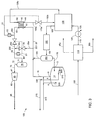
- Figure 1 shows a method of and apparatus 1 for handling a boil off gas stream 15 from a cryogenically stored liquefied hydrocarbon inventory 11 stored in a liquefied hydrocarbon storage tank 10.
- Liquefied hydrocarbon or hydrocarbon mixtures such as liquefied natural gas, may be stored under cryogenic conditions, at or near atmospheric pressure.
- the liquefied hydrocarbon inventory 11 in the storage tank 10 may be provided via a first inlet 3, by adding a liquefied hydrocarbon stream 175.
- the liquefied hydrocarbon stream 175 can be provided by a liquefaction unit and this is discussed in greater detail below.
- the storage tank may be that of an LNG carrier vessel, or may be a vessel or liquefaction unit storage tank supplied with the boil off gas from the loading of such a vessel.
- a degree of vaporisation of the liquefied hydrocarbon is to be expected due to temperature fluctuations within the liquefied hydrocarbon storage tank 10, or the pipework conveying the liquefied hydrocarbon to the storage tank 10.
- This vaporised hydrocarbon such as vaporised LNG, is flammable and can be removed from the storage tank 10 via outlet 5 as a vaporised hydrocarbon stream, normally termed a boil off gas (BOG) stream 15.
- BOG boil off gas
- the tank may be above the storage temperature of the liquefied hydrocarbon, such that the liquefied hydrocarbon will cool the tank, resulting in a portion of the hydrocarbon being vaporised.
- vaporised hydrocarbon returned from the carrier vessel by a blower during the loading operation may be superheated by the blower.
- Such vaporised hydrocarbon will be at a higher temperature that vaporised gas from a tank in a full, holding state.
- the temperature of the BOG stream 15 may vary in the range of -140 to -165 °C. The lower temperatures in this range may occur in holding mode while the higher temperatures in the range may occur in loading mode.
- the method and apparatus 1 disclosed herein seeks to provide a temperature controlled BOG stream 55.
- a temperature controlled BOG stream 55 can be further processed in further equipment, for example pressurised in an optional BOG compressor 80, without departing from the operational envelope of the equipment.
- the BOG stream 15 is passed to a first flow splitting device 220, in which it is divided into a boil off gas heat exchanger feed stream 25 and a boil off gas bypass stream 35.
- the BOG heat exchanger feed stream 25 is passed to the first inlet 41 of a boil off gas heat exchanger 40.
- the BOG heat exchanger 40 can be selected from the group consisting of printed circuit heat exchanger and spool wound heat exchanger.
- the BOG heat exchanger feed stream 25 is warmed against a process stream 135 provided to a second inlet 42 of the BOG heat exchanger 40, to provide a warmed boil off gas stream 45 at a first outlet 43 and a cooled process stream 195 at a second outlet 44.
- the process stream 135 may be any appropriate process stream available which requires to be cooled.
- the process stream 135 should have a temperature greater than that of the BOG heat exchanger feed stream 25, and thus the boil off gas stream 15. It is preferred that the process stream 135 is provided at a set process stream temperature, although this is not essential.
- the process stream 135 can have a temperature in the range of -20 to -50 °C. In this way, a part of the cold energy present in the BOG heat exchanger feed stream 25 is not wasted by heating against an ambient heat source and is instead passed to another process stream.
- a first temperature controller 50 determines the temperature of the warmed BOG stream 45 as a measured first temperature (T1).
- the first temperature controller 50 also has a first set point temperature (SP1), which can be input by an operator.
- the first temperature controller 50 seeks to move the first temperature (T1) of the warmed BOG stream 45 to the first set point temperature (SP1).
- the first temperature controller 50 brings about the adjustment of the temperature of the warmed BOG stream 45 by controlling the mass flow of the process stream 135 through the BOG heat exchanger 40.
- the mass flow of the process stream 135 through the BOG heat exchanger 40 is controlled by a process stream valve (not shown), which is placed in a conduit, either upstream or downstream of the heat exchanger 40, such that by adjusting the valve, the mass flow of the process stream 135 though the heat exchanger 400 can be changed.
- a process stream valve (not shown), which is placed in a conduit, either upstream or downstream of the heat exchanger 40, such that by adjusting the valve, the mass flow of the process stream 135 though the heat exchanger 400 can be changed.
- the embodiments of Figures 2 and 3 show possible locations for the process stream valve.
- the setting of the process stream valve is adjusted by a process stream actuator instructed by a process valve control signal from the first temperature controller 50. For instance, if the measured first temperature is less than the first set point temperature, the first set point controller 50 will transmit a process valve control signal instructing the process stream actuator to change the setting of the process stream valve to increase the mass flow of the process stream 135 through the BOG heat exchanger 40, increasing the warming of the BOG heat exchanger feed stream 25. Similarly, if the measured first temperature is greater than the first set point temperature, the first set point controller 50 will transmit a process valve control signal instructing the process stream actuator to change the setting of the process stream valve to decrease the mass flow of the process stream 135 through the BOG heat exchanger 40, increasing the cooling of the BOG heat exchanger feed stream 25.
- the first set point temperature may be in the range of -21 to -58 °C, more preferably approximately -45 to -50 °C.
- the choice of the first set point temperature may depend upon the designed approach temperature of process stream 135 to the BOG heat exchanger 40.
- the first set point temperature may be, for example, a few degrees Centigrade lower than the temperature of the process stream 135, for instance 3 °C lower.
- the input first set point temperature of the first temperature controller 50 may depend upon the operational mode of the facility.
- the first temperature controller 50 can operate to warm the boil off gas against the process stream 135 in the BOG heat exchanger 40.
- the first set point temperature may be set to a different value depending upon whether the facility is operating in holding mode or loading mode. For instance, the first set point temperature may be lower in loading mode than in holding mode.
- the warmed BOG stream 45 provided by the BOG heat exchanger 40 is then passed to a first stream combining device 230, in which it is combined with the BOG bypass stream 35 to provide a temperature controlled BOG stream 55.
- the temperature of the temperature controlled BOG stream 55 is determined by the relative mass flows and temperatures of the warmed BOG stream 45 and the BOG bypass stream 55, the latter being at a colder temperature because it has not been warmed in the BOG heat exchanger 40.
- a second temperature controller 60 determines the temperature of the temperature controlled BOG stream 55 as a measured second temperature (T2).
- the second temperature controller 60 is provided with a second set point temperature (SP2), which can be input by an operator.
- the second temperature controller 60 seeks to move the second temperature (T2) of temperature controlled BOG stream 55 to the second set point temperature (SP2).
- the second temperature controller 60 brings about the adjustment of the temperature of the temperature controlled BOG stream 55 by controlling the relative mass flows of the warmed BOG stream 45 and the BOG bypass stream 35.
- the second temperature controller 60 can operate to reduce the warming provided by the BOG heat exchanger 40 to the BOG heat exchanger feed stream 25 by diverting the boil off gas along BOG bypass stream 35.
- the second set point will be lower than the first set point temperature. This would require cooling of the warmed BOG stream 45 such that the colder BOG bypass stream 35 has a positive mass flow during both loading and holding modes.
- the BOG bypass stream 35 thus operates to lower the temperature of the warmed BOG stream 45 when it is added in first stream combining device 230.
- the relative mass flows of the warmed BOG stream 45 and the BOG bypass stream 35 can be controlled by one or more flow control valves (not shown). Such flow controlling valves can be placed in any conduit allowing the adjustment of the mass flow of the relevant stream.
- the embodiments of Figures 2 and 3 show possible locations for these flow control valves, such as in one or more of the BOG bypass stream 35, the BOG heat exchanger feed stream 25 and the warmed BOG stream 45.
- the setting of the one or more flow control valves is adjusted by a flow control actuator instructed by a flow control valve signal from the second temperature controller 60. For instance, if the measured second temperature is less than the second set point temperature, the second set point controller 60 will transmit a flow control valve signal instructing one or more flow control actuators to change the setting of one or more flow control valves to increase the relative mass flow of the warmed BOG stream 45 compared to the BOG bypass stream 35, increasing the warming of the BOG bypass stream 35 by the warmed BOG stream 45.
- the second set point controller 60 will transmit a flow control valve signal instructing the one or more of the flow control actuators to change the setting of one or more flow control valves to decrease the relative mass flow of the warmed BOG stream 45 compared to the BOG bypass stream 35, increasing the cooling of the warmed BOG stream 45 by the BOG bypass stream 35.
- the input second set point temperature of the second temperature controller 60 may depend upon the operational mode of the facility.
- the temperature and mass flow of the boil off gas may be low compared to loading mode.
- the temperature of the BOG stream 15 is normally lower than in loading mode because the only heat entering the storage tank and associated pipework is as a result of leakage through the insulation.
- the mass flow of the boil off gas is normally lower than in loading mode because there is no carrier vessel to generate additional boil off gas.
- the first temperature controller 50 may operate to warm the boil off gas against the process stream 135. If the warmed BOG stream 45 is provided at or close to the second set point temperature, the one or more flow control valves (not shown) of the second temperature controller 60 may operate to significantly restrict the mass flow of the BOG bypass stream 35. Thus, the major mass flow would be to the BOG heat exchanger 40 through BOG heat exchanger feed stream 25, as controlled by the first temperature controller 50 If the warmed BOG stream 45 is provided above the second set point temperature, the one or more flow control valves operated by the second temperature controller 60 may operate to provide mass flow of BOG bypass stream 35 to cool the warmed BOG stream 45 to move the measured second temperature of the temperature controlled BOG stream 55 towards the second set point temperature.
- the temperature of BOG feed stream 15 may be higher than in holding mode due to, for instance, superheating from the blowers transferring boil off gas from the carrier vessel.
- the second temperature controller 60 may detect an increase in the temperature of the controlled temperature BOG stream 55 as a result of the warmer BOG bypass stream 35. As less warming of the boil off gas may be required to provide a stable controlled temperature BOG stream 55, the second temperature controller 60 can operate to increase the mass flow of the BOG bypass stream 35 in relation to the BOG heat exchanger feed stream 25, thus reducing the heat input to the boil off gas.
- the mass flow of the boil off gas may significantly increase during loading mode, because of the additional boil off gas produced in the carrier vessel and returned to the apparatus 1. This higher mass flow can be accommodated by increasing the mass flow of the BOG bypass stream 35, which is warmer than in holding mode, compared to the mass flow of the BOG heat exchanger feed stream 25.
- the second set point temperature may be gradually lowered from the set point during holding mode to a different set point during loading mode. This action may be carried out, for instance, if the duty required of the BOG heat exchanger 40 exceeds its design capacity.
- Lowering input second set point temperature decreases the target temperature of the temperature controlled BOG stream. This action will result in a decrease in the duty required from the BOG heat exchanger. This action may particularly be carried out during loading mode if the BOG heat exchanger reaches its maximum designed operating duty. Such a decrease in the measured second temperature of the temperature controlled BOG stream may for instance move the optional BOG compressor 80 away from its designed operating temperature, lowering the efficiency of the compression process.
- the second set point temperature and the measured second temperature should preferably be maintained within the designed operational envelope of the BOG compressor in order to avoid damage.
- an optional warmed BOG stream heater 65 may be provided in the warmed BOG stream to further increase its temperature.
- the optional heater 65 if provided, can be used to increase the first measured temperature towards the first set point temperature and/or to provide an increased mass flow rate of the warmed BOG stream at the first set point temperature.
- the warmed BOG stream heater 65 can also be controlled by the first temperature controller.
- the method and apparatus disclosed herein can provide a temperature controlled BOG stream 55.
- the method and apparatus disclosed herein can be utilised as part of a liquefaction process for a hydrocarbon feed stream.
- the hydrocarbon feed stream may be any suitable gas stream to be cooled and liquefied, but is usually a natural gas stream obtained from natural gas or petroleum reservoirs.
- the hydrocarbon feed stream may also be obtained from another source, also including a synthetic source such as a Fischer-Tropsch process.
- a natural gas stream is a hydrocarbon composition comprised substantially of methane.
- the hydrocarbon feed stream comprises at least 50 mol% methane, more preferably at least 80 mol% methane.
- Hydrocarbon compositions such as natural gas may also contain non-hydrocarbons such as H 2 O, N 2 , CO 2 , Hg, H 2 S and other sulphur compounds, and the like.
- the natural gas may be pre-treated before cooling and any liquefying. This pre-treatment may comprise reduction and/or removal of undesired components such as CO 2 and H 2 S or other steps such as early cooling, pre-pressurizing or the like. As these steps are well known to the person skilled in the art, their mechanisms are not further discussed here.
- hydrocarbon feed stream may also include a composition prior to any treatment, such treatment including cleaning, dehydration and/or scrubbing, as well as any composition having been partly, substantially or wholly treated for the reduction and/or removal of one or more compounds or substances, including but not limited to sulphur, sulphur compounds, carbon dioxide, water, Hg, and one or more C2+ hydrocarbons.
- natural gas may contain varying amounts of hydrocarbons heavier than methane such as in particular ethane, propane and the butanes, and possibly lesser amounts of pentanes and aromatic hydrocarbons.
- hydrocarbons heavier than methane such as in particular ethane, propane and the butanes, and possibly lesser amounts of pentanes and aromatic hydrocarbons.
- the composition varies depending upon the type and location of the gas.
- C2+ hydrocarbons can be separated from, or their content reduced in a hydrocarbon feed stream by a demethaniser, which will provide an overhead hydrocarbon stream which is methane-rich and a bottoms methane-lean stream comprising the C2+ hydrocarbons.
- the bottoms methane-lean stream can then be passed to further separators to provide Liquefied Petroleum Gas (LPG) and condensate streams.
- LPG Liquefied Petroleum Gas
- the hydrocarbon stream so produced can be cooled.
- the cooling could be provided by a number of methods known in the art.
- the hydrocarbon stream is passed against one or more refrigerant streams in one or more refrigerant circuits.
- a refrigerant circuit can comprise one or more refrigerant compressors to compress an at least partly evaporated refrigerant stream to provide a compressed refrigerant stream.
- the compressed refrigerant stream can then be cooled in a cooler, such as an air or water cooler, to provide the refrigerant stream.
- the refrigerant compressors can be driven by one or more turbines.
- the cooling of the hydrocarbon stream can be carried out in one or more stages.
- Initial cooling also called pre-cooling or auxiliary cooling, can be carried out using a pre-cooling mixed refrigerant of a pre-cooling refrigerant circuit, in two or more pre-cooling heat exchangers, to provide a pre-cooled hydrocarbon stream.
- the pre-cooled hydrocarbon stream is preferably partially liquefied, such as at a temperature below 0°C.
- such pre-cooling heat exchangers could comprise a pre-cooling stage, with any subsequent cooling being carried out in one or more main heat exchangers to liquefy a fraction of the hydrocarbon stream in one or more main and/or sub-cooling cooling stages.
- each cooling stage may comprise one to five heat exchangers.
- the or a fraction of a hydrocarbon stream and/or the mixed refrigerant may not pass through all, and/or all the same, heat exchangers of a cooling stage.
- the hydrocarbon may be cooled and liquefied in a method comprising two or three cooling stages.
- a pre-cooling stage is preferably intended to reduce the temperature of a hydrocarbon feed stream to below 0°C, usually in the range -20°C to -70°C.
- a main cooling stage is preferably separate from the pre-cooling stage. That is, the main cooling stage comprises one or more separate main heat exchangers.
- a main cooling stage is preferably intended to reduce the temperature of a hydrocarbon stream, usually at least a fraction of a hydrocarbon stream cooled by a pre-cooling stage, to below -100°C.
- Heat exchangers for use as the two or more pre-cooling or any main heat exchangers are well known in the art.
- the pre-cooling heat exchangers are preferably shell and tube heat exchangers.
- At least one of any of the main heat exchangers is preferably a spool-wound cryogenic heat exchanger known in the art.
- a heat exchanger could comprise one or more cooling sections within its shell, and each cooling section could be considered as a cooling stage or as a separate 'heat exchanger' to the other cooling locations.
- one or both of the mixed pre-cooling refrigerant stream and any mixed main refrigerant stream can be passed through one or more heat exchangers, preferably two or more of the pre-cooling and main heat exchangers described hereinabove, to provide cooled mixed refrigerant streams.
- the mixed refrigerant in a mixed refrigerant circuit such as the pre-cooling refrigerant circuit or any main refrigerant circuit may be formed from a mixture of two or more components selected from the group comprising: nitrogen, methane, ethane, ethylene, propane, propylene, butanes, pentanes, etc.
- One or more other refrigerants may be used, in separate or overlapping refrigerant circuits or other cooling circuits.
- the pre-cooling refrigerant circuit may comprise a mixed pre-cooling refrigerant.
- the main refrigerant circuit may comprise a mixed main refrigerant.
- a mixed refrigerant or a mixed refrigerant stream as referred to herein comprises at least 5 mol% of two different components. More preferably, the mixed refrigerant comprises two or more of the group comprising: nitrogen, methane, ethane, ethylene, propane, propylene, butanes and pentanes.
- a common composition for a pre-cooling mixed refrigerant can be: Methane (C1) 0-20 mol% Ethane (C2) 5-80 mol% Propane (C3) 5-80 mol% Butanes (C4) 0-15 mol%
- Methane (C1) 0-20 mol% Ethane (C2) 5-80 mol% Propane (C3) 5-80 mol% Butanes (C4) 0-15 mol%
- the total composition comprises 100 mol%.
- a common composition for a main cooling mixed refrigerant can be: Nitrogen 0-25 mol% Methane (C1) 20-70 mol% Ethane (C2) 30-70 mol% Propane (C3) 0-30 mol% Butanes (C4) 0-15 mol%
- the total composition comprises 100 mol%.
- the pre-cooled hydrocarbon stream such as a pre-cooled natural gas stream can be further cooled to provide a liquefied hydrocarbon stream, such as an LNG stream.
- a liquefied hydrocarbon stream such as an LNG stream.
- the liquefied hydrocarbon stream may be further processed, if desired.
- the obtained liquefied hydrocarbon may be depressurized by means of one or more expansion devices such as a Joule-Thomson valve and/or a cryogenic turbo-expander.
- the liquefied hydrocarbon stream can be passed through an end gas/liquid separator such as an end-flash vessel to provide an end-flash gas stream overhead and a liquid bottom stream, the latter for storage in one or more liquefied hydrocarbon storage tank as the liquefied product, such as LNG.
- an end gas/liquid separator such as an end-flash vessel to provide an end-flash gas stream overhead and a liquid bottom stream, the latter for storage in one or more liquefied hydrocarbon storage tank as the liquefied product, such as LNG.
- the boil off gas from such a storage tank can be treated according to the method and apparatus described herein.
- Figure 2 shows a method and apparatus 100 for treating, cooling and liquefying a hydrocarbon feed stream 105 to provide a liquefied hydrocarbon stream 175.
- the liquefied hydrocarbon stream 175 can be passed to liquefied hydrocarbon storage tank 10, which can provide a BOG stream 15, which can be treated to produce a temperature controlled BOG stream 55.
- the hydrocarbon feed stream 105 may be any hydrocarbon or mixture or hydrocarbons, such as natural gas.
- the hydrocarbon feed stream 105 can be passed to a treatment unit 110, in which the feed stream is treated to remove unwanted contaminants, such as acid gasses and heavier hydrocarbons. Such treatments are known to the skilled person.
- Acid gasses may be removed from the feed stream by solvent extraction, to provide acid gas stream 95a.
- Heavier hydrocarbons may be removed by separation in one or more separation columns, such as a scrub column, to provide natural gas liquids (NGLs).
- a NGL stream 95b is shown leaving the treatment unit 110. Quantities of water present in the hydrocarbon feed stream 105 may also be removed.
- Treatment unit 110 provides a treated hydrocarbon stream 115.
- Treated hydrocarbon stream 115 will be a methane rich stream having a reduced content of acid gasses and NGLs compared to the hydrocarbon feed stream 115.
- Treated hydrocarbon stream 115 can be passed to a pre-cooling unit comprising one or more pre-cooling heat exchangers 120.
- the one or more pre-cooling heat exchangers 120 can cool the treated hydrocarbon stream 115 against a refrigerant, such as a pre-cooling refrigerant in a pre-cooling refrigerant circuit to provide a pre-cooled hydrocarbon stream 125.
- the pre-cooled hydrocarbon stream 125 can then be passed to a pre-cooling stream splitting device, which provides a main cooling hydrocarbon feed stream 145 and a process stream 135a, which in this case in a main cooling hydrocarbon bypass stream.
- the main cooling hydrocarbon feed stream 145 can be passed to a main cooling unit comprising one or more main cooling heat exchangers 130.
- the one or more main cooling heat exchangers 130 can cool the main cooling hydrocarbon feed stream 145 against a refrigerant, such as a main refrigerant in a main refrigerant circuit to at least partially, preferably fully, liquefy the hydrocarbon.
- a refrigerant such as a main refrigerant in a main refrigerant circuit
- One or more main heat exchangers provide a liquefied hydrocarbon stream 155a.
- the liquefied hydrocarbon stream 155a is an at least partially liquefied hydrocarbon stream, and preferably fully liquefied hydrocarbon stream.
- the at least partially, preferably fully, liquefied hydrocarbon stream 155a can be combined with cooled process stream 195 to provide (combined) at least partially, preferably fully, liquefied hydrocarbon stream 155b.
- the (combined) at least partially, preferably fully, liquefied hydrocarbon stream 155b can then be expanded in one or more end expansion devices 150, such as one or both of a Joule-Thomson valve and a turbo-expander, to provide a expanded partially liquefied hydrocarbon stream 165.
- Expanded partially liquefied hydrocarbon stream 165 is a two phase stream comprising liquid and vapour components.
- the expanded partially liquefied hydrocarbon stream 165 can be passed to an end gas/liquid separator 160, such as an end flash vessel, to provide a liquefied hydrocarbon stream 175 as a bottoms stream and an overhead hydrocarbon stream 185, also known as end flash gas.
- the liquefied hydrocarbon stream 175 can be a LNG stream when the hydrocarbon feed stream 105 is natural gas.
- the liquefied hydrocarbon stream 175 can be passed to the first inlet 4 of a liquefied hydrocarbon storage tank 10.
- the liquefied hydrocarbon storage tank 10 may comprise a submerged pump 210 for providing the liquefied hydrocarbon to a second outlet 6, where it leaves storage tank 10 as liquefied hydrocarbon feed stream 215.
- the liquefied hydrocarbon feed stream 215 may transfer the liquefied hydrocarbon to further storage tanks (not shown), for instance in a carrier vessel, such as an LNG carrier.
- boil off gas may be produced in the process of cooling the further storage tanks and/or connecting pipework to the temperature of the liquefied hydrocarbon. This boil of gas can be passed back to second inlet 4 of the liquefied hydrocarbon storage tank 10 as loading boil off gas stream 315. If desired, at least a part of the loading boil off gas stream 315 can be passed directly to boil off gas stream 15 along conduit 335.
- the BOG stream 15 may also comprise the overhead hydrocarbon from the end gas/liquid separator 160 from overhead hydrocarbon stream 175.
- the BOG stream 15 may then be processed according to the method and apparatus described herein, to provide a temperature controlled BOG stream 55.
- BOG stream 15 is passed to first flow splitting device 220, where it is separated into the BOG heat exchanger feed stream 25a and BOG bypass stream 35a.
- the BOG heat exchanger feed stream 25a is passed to a heat exchanger feed stream flow controlling valve 20, which controls the mass flow of the stream to provide a (controlled) BOG heat exchanger feed stream 25b to first inlet 41 of the BOG heat exchanger 40.
- the BOG bypass stream 35a is passed to a bypass stream flow controlling valve 30, which controls the mass flow of the stream to provide a (controlled) BOG bypass stream 35b.
- the BOG stream flow control valve 20 and bypass stream flow control valve 30 are connected to flow control actuators (not shown) which control the setting of the valves.
- the flow control actuators receive flow control signals along flow control signal line 61 from the second temperature controller 60.
- changing the setting of flow control valves 20, 30 will adjust the relative mass flow of the (controlled) BOG heat exchanger feed stream 25b (and thus warmed BOG stream 45) and the (controlled) BOG bypass stream 35b, such that the temperature of the temperature controlled BOG stream 55 can be maintained at or close to the second set point temperature.
- the temperature controlled BOG stream 55 can then be passed to the inlet 71 of a boil off gas compressor knock out drum 70 in which liquid from the temperature controlled BOG stream 55 can be removed to provide a boil off gas compressor feed stream 75 as an overhead stream at outlet 72.
- the BOG compressor feed stream 75 can be passed to the inlet 81 of a boil off gas compressor 80.
- the BOG compressor feed stream 75 is a temperature controlled stream because it is derived from the temperature controlled BOG stream 55.
- the suction of the BOG compressor 80 is thus provided with a stream at a controlled temperature. This temperature control allows the operation of the BOG compressor 80 to be maintained within its operational envelope.
- the warming of the (controlled) BOG heat exchanger feed stream 25b is provided by a process stream.
- the process stream is a main cooling hydrocarbon bypass stream 135a provided from the pre-cooled hydrocarbon stream 125 by a pre-cooling stream splitting device as discussed previously.
- the main cooling hydrocarbon bypass stream 135a may be provided at a fixed temperature, as produced by one or more pre-cooling heat exchangers 120, such as at least one low pressure propane heat exchanger.
- the main cooling hydrocarbon bypass stream 135a is passed to a process stream valve 170 to provide a (controlled) main cooling hydrocarbon bypass stream 135b which is passed to the second inlet 42 of the BOG heat exchanger 40.
- the mass flow of the (controlled) main cooling hydrocarbon bypass stream 135b is controlled by the setting of the process stream valve 170.
- the setting of the process stream valve 170 is controlled by a process stream actuator, which receives process control signals from the first temperature controller 50 along process control signal line 51. In this way, the first temperature of the warmed BOG stream 45 can be controlled by changing the mass flow of the (controlled) main cooling hydrocarbon bypass stream 135b.
- the BOG heat exchanger cools the (controlled) main cooling hydrocarbon bypass stream 135b against the (controlled) BOG heat exchanger feed stream 25b to provide cooled main cooling hydrocarbon bypass stream 195 as a cooled process stream.
- the cooled main cooling hydrocarbon bypass stream 195 is at least partially, preferably fully, liquefied it can be combined with the at least partially, preferably fully, liquefied hydrocarbon stream 155a from the one or more main heat exchangers 130 to provide (combined) at least partially, preferably fully, liquefied hydrocarbon stream 155b. In this way, a portion of the cold energy from the boil off gas can be recycled to a hydrocarbon process stream, so that it can bypass the one or more main heat exchangers 130 in order to reduce the cooling duty of the one or more main heat exchangers 130.
- Figure 3 shows an alternative method and apparatus 100 for treating, cooling and liquefying a hydrocarbon feed stream 105 to provide a liquefied hydrocarbon stream 175.
- the liquefied hydrocarbon stream 175 can be passed to liquefied hydrocarbon storage tank 10, which can provide a BOG stream 15, which can be treated to produce a temperature controlled BOG stream 55.
- the process stream 135c comprises main refrigerant from the one or more main heat exchangers 130.
- the process stream 135c may be a light mixed refrigerant stream derived from a mixed refrigerant separation device in a mixed refrigerant circuit, such as that described in US Patent No. 6,370,910 .
- a light mixed refrigerant stream may be derived from a mixed refrigerant stream by forming a partly condensed mixed refrigerant stream and separating the vapour phase from the partly condensed mixed refrigerant stream, typically by means of the mixed refrigerant separation device, to form the light mixed refrigerant stream.
- the light mixed refrigerant stream 135c is passed to the second inlet of the BOG heat exchanger 40, where it is warmed against BOG heat exchanger feed stream 25 to provide a cooled light mixed refrigerant stream 195a.
- the mass flow of the light mixed refrigerant through the BOG heat exchanger 40 is controlled by a process stream valve 170a downstream, rather than upstream, of the BOG heat exchanger 40.
- the process stream valve 170a provides a (controlled) cooled light mixed refrigerant stream 195b which can be returned to the one or more heat exchangers 130.
- the process stream valve 170a is controlled by a process stream actuator provided with a process control signal in process control signal line 51 from first temperature controller 50. In this way, the first temperature of the warmed BOG stream can be controlled.
- the process stream valve 170a may produce a large pressure drop in the process stream, such that a low pressure regime with two phase flow may occur downstream of the valve. It is preferred to produce such a low pressure regime downstream of the BOG heat exchanger 40. If the process stream valve 170a is located upstream of the BOG heat exchanger 40, the exchanger must be adapted to accommodate two phase flow. This can increase the cost of the BOG heat exchanger 40.
- the embodiment of Figure 3 also shows an alternative location for the BOG stream flow control valve 20a, controlled by second temperature controller 60. Rather than being located upstream of the BOG heat exchanger 40 in BOG heat exchanger feed stream 25, it is provided downstream in the warmed BOG stream 45a which exits the first outlet 43 of the heat exchanger 40.
- the warmed BOG stream 45a is passed to BOG stream flow control valve 20a, which provides a (controlled) warmed BOG stream 45b to be combined with the (controlled) BOG bypass stream 35b in the first stream combining device 230.
- the BOG stream flow control valve 20a downstream of the BOG heat exchanger 40 operates to control the mass flow of the warmed BOG stream/ BOG heat exchanger feed stream 25.
- bypass stream flow control valve 30 In combination with the bypass stream flow control valve 30, it is possible to control the relative mass flows of the warmed BOG stream/ BOG heat exchanger feed stream 25 and the BOG bypass stream 35a/ (controlled) BOG bypass stream 35b to provide the temperature controlled BOG stream at the second set point temperature.
- the first temperature controller 50 can be situated either upstream or downstream of BOG stream flow control valve 20a.
- Figure 3 shows the first temperature controller 50 situated upstream of BOG stream flow control valve 20a in the warmed BOG stream 45a.
- the first temperature controller 50 can be situated to measure the temperature of the cooled process stream 195.
- the first temperature controller 50 is placed between the BOG heat exchanger 40 and the process stream valve 170a, such that the first temperature can be determined prior to any pressure or temperature changes to the cooled process stream 195 arising from the operation of the process stream valve 170a.
- the first set point temperature would therefore differ from that proposed for the embodiments of Figures 1 and 2 , and could be in the range of -137 to -162 °C for the cooled process stream 195.
- the boil off gas When in holding mode, the boil off gas will be produced primarily from the cryogenic storage tanks.
- the temperature of the boil off gas will be close to cryogenic temperature.
- the boil off gas from the storage tanks may be at a temperature of less than -150 °C.
- a liquefied hydrocarbon carrier such as an LNG carrier vessel
- the facility will move from holding mode to loading mode.
- the pipework connecting the cryogenic storage tanks of the liquefaction facility and the liquefied hydrocarbon carrier, and the cryogenic storage tanks of the liquefied hydrocarbon carrier may be warmer than cryogenic temperature.
- the loading process may thus produce boil off gas from liquefied hydrocarbon passing through the connecting pipework and into carrier storage tanks which is significantly warmer than the boil off gas produced by the liquefaction facility cryogenic storage tanks in holding mode. This will be particularly so if the liquefied hydrocarbon itself is used to provide the cooling to the connecting pipework and carrier storage tanks.
- the blowers transferring the boil off gas generated in the carrier vessel to the liquefaction facility may superheat the gas, increasing the temperature of the boil off gas.
- boil off gas may be produced at a higher temperature and in greater quantity than that produced during holding mode.
- the first temperature controller can operate to maintain the measured first temperature at the first set point by changing the mass flow of the process stream to provide the required heat to the BOG heat exchanger to warm the BOG heat exchanger feed stream until the first set point temperature is reached.
- the second set point temperature of the second temperature controller When the second set point temperature of the second temperature controller is selected to be less than the first set point temperature, this can be achieved by reducing the temperature of the warmed BOG stream can be to the second set point temperature by combination with the cooler BOG bypass stream.
- the BOG bypass stream can be at a lower temperature than the first set point temperature because it has not passed through the BOG heat exchanger.
- the BOG bypass stream will also usually be colder than the second set point temperature.
- the second temperature controller can control the relative mass flow rates of one or both of the warmed BOG stream and the BOG bypass stream to achieve the second set point temperature.
- the second temperature controller can increase the mass flow rate of the BOG bypass stream and/or reduce the mass flow rate of the BOG heat exchanger feed stream.
- the second temperature controller can decrease the mass flow rate of the BOG bypass stream and/or increase the mass flow rate of the BOG heat exchanger feed stream.
- the first temperature controller can act to maintain the warmed BOG stream at the first set point temperature by altering the mass flow rate of the process stream to change the duty of the BOG heat exchanger. This may involve increasing the mass flow of the process stream to provide additional warming to the higher mass flow of the BOG feed stream, or decreasing the mass flow of the process stream if less warming of the BOG feed stream is required as a result of its higher temperature.
- the BOG heat exchanger can be sized to provide the maximum required duty to the BOG feed stream.
- the additional duty resulting from the increased mass flow of the BOG stream will normally exceed the decrease in duty as a result of the increase in temperature of the BOG stream. Loading mode can therefore produce the maximum BOG heat exchanger duty.
- the second set point temperature of the second temperature controller when the second set point temperature of the second temperature controller is selected to be less than the first set point temperature, the temperature of the warmed BOG stream will be reduced to the second set point temperature by combination with the BOG bypass stream.
- the temperature of the BOG bypass stream used to cool the warmed BOG stream When moving from holding mode to loading mode, the temperature of the BOG bypass stream used to cool the warmed BOG stream will increase. This will be detected as a rise in the measured second temperature by the second temperature controller. Consequently, the second temperature controller can operate to increase the mass flow of the BOG bypass stream and/or reduce the mass flow of the BOG heat exchanger feed stream to lower the temperature of the temperature controlled BOG stream towards the second set point temperature.
- the BOG bypass stream which is at a lower temperature than the warmed BOG stream because it has not been heated in the BOG heat exchanger, can provide cooling to the warmed BOG stream which is passed downstream to the BOG heat exchanger.
- the temperature and mass flow of the boil off gas stream may fall. This may be detected as a fall in the second measured temperature below the second set point temperature as a result of a drop in the temperature of the BOG bypass stream. For this reason it is preferred that a mass flow in the BOG bypass stream is maintained.
- the second temperature controller will react by lowering the mass flow of the BOG bypass stream and/or increasing the mass flow of the BOG heat exchanger feed stream in order to raise the temperature of the temperature controlled BOG stream towards the second set point temperature.
- the first temperature controller may also detect a fall in the measured first temperature below the first set point temperature as a result of the drop in temperature of the BOG heat exchanger feed stream, which in the absence of a change in the duty provided by the process stream will result in a drop in the temperature of the warmed BOG stream.
- the first temperature controller may respond by increasing the mass flow of the process stream in order to provide additional cooling of the now lower temperature BOG heat exchanger feed stream, resulting in an increase in the temperature of the warmed BOG stream towards the first set point temperature.
- the first and second temperature controllers may detect a reduction in the measured first and second temperatures simultaneously.
- the temperature controlled boil off gas stream can be provided to the BOG compressor at a desired temperature.
- a temperature can be in the range of the temperature of the boil off gas stream and the process stream.
- the temperature of the boil off gas stream may be dependent upon whether the facility is in holding or loading mode.
- the present invention can operate to prevent a stream of too low a temperature, such as during holding mode, being passed to the BOG compressor, by providing warming from the process stream.
Landscapes
- Engineering & Computer Science (AREA)
- Mechanical Engineering (AREA)
- General Engineering & Computer Science (AREA)
- Physics & Mathematics (AREA)
- Thermal Sciences (AREA)
- Chemical & Material Sciences (AREA)
- Combustion & Propulsion (AREA)
- Chemical Kinetics & Catalysis (AREA)
- General Chemical & Material Sciences (AREA)
- Oil, Petroleum & Natural Gas (AREA)
- Filling Or Discharging Of Gas Storage Vessels (AREA)
Claims (15)
- Verfahren zur Handhabung eines Boil-off-Gasstroms (15) aus einem kryogen gelagerten verflüssigten Kohlenwasserstoffvorrat (11), umfassend wenigstens die Schritte:- Bereitstellen eines Boil-off-Gasstroms (BOG-Stroms) (15) aus einem Lagertank (10) für verflüssigten Kohlenwasserstoff; und- Wärmetausch eines BOG-Wärmetauscher-Einsatzstroms (25) in einem BOG-Wärmetauscher (40) gegen einen Prozessstrom (135), wobei der Massenstrom des Prozessstroms (135) in Reaktion auf eine gemessene erste Temperatur gesteuert wird, um die gemessene erste Temperatur hin zu einer ersten Sollwerttemperaur zu verschieben;
dadurch gekennzeichnet, dass der Wärmetausch des BOG-Wärmetauscher-Einsatzstroms (25) im BOG-Wärmetauscher (40) gegen den Prozessstrom (135) einen erwärmten BOG-Strom (45) und einen gekühlten Prozessstrom (195) bereitstellt, und darin, dass das Verfahren ferner die Schritte umfasst:- Auftrennen des BOG-Stroms (15) in den BOG-Wärmetauscher-Einsatzstrom (25) und in einen BOG-Bypassstrom (35); und- Vereinigen des erwärmten BOG-Stroms (45) mit dem BOG-Bypassstrom (35), um einen temperaturgesteuerten BOG-Strom (55) bereitzustellen;
wobei die gemessene erste Temperatur wenigstens eine von (i) dem erwärmten BOG-Strom (45) und (ii) dem gekühlten Prozessstrom (195) ist, und wobei der Massenstrom vom BOG-Wärmetauscher-Einsatzstrom (25) oder vom BOG-Bypassstrom (35) oder von beiden in Reaktion auf eine gemessene zweite Temperatur des temperaturgesteuerten BOG-Stroms (55) gesteuert wird, um die gemessene zweite Temperatur hin zu einer zweiten Sollwerttemperaur zu verschieben. - Verfahren nach Anspruch 1, ferner umfassend die Schritte:- Leiten des temperaturgesteuerten BOG-Stroms (55) zu einem BOG-Verdichter-Abscheidebehälter ("knock out drum") (70), um einen BOG-Verdichter-Einsatzstrom (75) bereitzustellen;- Verdichten des BOG-Verdichter-Einsatzstroms (75) in einem BOG-Verdichter (80), um einen verdichteten BOG-Strom (85) bereitzustellen.
- Verfahren nach Anspruch 1 oder Anspruch 2, wobei der Prozessstrom (135) mit einer voreingestellten Prozessstromtemperatur bereitgestellt wird.
- Verfahren nach einem der vorstehenden Ansprüche, wobei die Steuerung des Massenstroms des Prozessstroms (135) in Reaktion auf die gemessene erste Temperatur des erwärmten BOG-Stroms (45) die Schritte umfasst:- Bestimmen der gemessenen ersten Temperatur des erwärmten BOG-Stroms (45) mit einer ersten Temperatursteuerung (50) mit einer ersten Sollwerttemperatur;- Verändern des Massenstroms des Prozessstroms (135) durch Einstellen eines Prozessstromventils (170), um die gemessene erste Temperatur hin zur ersten Sollwerttemperaur zu verschieben.
- Verfahren nach einem der vorstehenden Ansprüche, wobei die Steuerung des Massenstroms vom BOG-Wärmetauscher-Einsatzstrom (25) oder vom BOG-Bypassstrom (35) oder von beiden in Reaktion auf die gemessene zweite Temperatur des temperaturgesteuerten BOG-Stroms (55) die Schritte umfasst:- Bestimmen der gemessenen zweiten Temperatur des temperaturgesteuerten BOG-Stroms (55) mit einer zweiten Temperatursteuerung (60) mit der zweiten Sollwerttemperaur;- Verändern des Massenstroms vom BOG-Wärmetauscher-Einsatzstrom (25) oder vom BOG-Bypassstrom (35) oder von beiden durch Einstellen eines Einsatzstromventils (20) bzw.
eines Bypassstromventils (30), um die gemessene zweite Temperatur hin zur zweiten Sollwerttemperaur zu verschieben. - Verfahren nach einem der vorstehenden Ansprüche, ferner umfassend:- Bereitstellen eines Kohlenwasserstoffeinsatzstroms (105);- Verflüssigen von wenigstens einem Teil (125,145) des Kohlenwasserstoffeinsatzstroms, umfassend einen Wärmetausch gegen wenigstens ein Kühlmittel, welches in einem Kühlmittelkreislauf im Kreis geführt wird, um einen verflüssigten Kohlenwasserstoffstrom (155,155a) bereitzustellen;- Zusetzen von wenigstens einem Teil (175) des verflüssigten Kohlenwasserstoffstroms (155,155a) zu dem kryogen gelagerten verflüssigten Kohlenwasserstoffvorrat (11) im Lagertank (10) für verflüssigten Kohlenwasserstoff.
- Verfahren nach Anspruch 6, wobei der Prozessstrom (135) wenigstens einen Teil (135a) aus dem Kohlenwasserstoffeinsatzstrom (105) umfasst, welcher Teil des Kohlenwasserstoffeinsatzstroms nach dessen Wärmetausch im BOG-Wärmetauscher (40) wenigstens teilweise zum kryogen gelagerten verflüssigten Kohlenwasserstoffvorrat (11) im Lagertank (10) für verflüssigten Kohlenwasserstoff zugesetzt wird.
- Verfahren nach Anspruch 7, wobei der Teil (135a) aus dem Kohlenwasserstoffeinsatzstrom (105) im Prozessstrom (135) von einem "Slip"-Strom gebildet wird, der wenigstens einen Teil des Wärmetausches gegen das wenigstens eine Kühlmittel, welches in einem Kühlmittelkreislauf im Kreis geführt wird, umgeht, um im BOG-Wärmetauscher (40) einem Wärmetausch unterzogen zu werden.
- Verfahren nach Anspruch 6, wobei der Prozessstrom (135) wenigstens einen Kühlmittelstrom (135c) umfasst, der aus dem wenigstens einen Kühlmittel, welches im Kühlmittelkreislauf im Kreis geführt wird, erhalten wird.
- Verfahren nach einem der Ansprüche 6 bis 9, wobei das Zusetzen des wenigstens einen Teils des verflüssigten Kohlenwasserstoffstroms (155,155a) zum kryogen gelagerten verflüssigten Kohlenwasserstoffvorrat (11) die Schritte umfasst:- Expandieren des verflüssigten Kohlenwasserstoffstroms (155,155a) in einem oder mehreren Endexpansionsvorrichtungen (150), um einen expandierten, wenigstens teilweise verflüssigten Kohlenwasserstoffstrom (165) bereitzustellen;- Leiten des expandierten, wenigstes teilweise verflüssigten Kohlenwasserstoffstroms (165) an ein End-Flash-Gefäß (160), um einen verflüssigten Kohlenwasserstoffstrom (175) und einen Kohlenwasserstoffkopfstrom (185) bereitzustellen;- Leiten des verflüssigten Kohlenwasserstoffstroms zum kryogenen Lagertank; und- Zusetzen des Kohlenwasserstoffkopfstroms (185) in den Boil-off-Gasstrom (15).
- Vorrichtung zur Handhabung eines Boil-off-Gasstroms (BOG-Stroms) (15) aus einem kryogen gelagerten verflüssigten Kohlenwasserstoffvorrat (11), welche Vorrichtung wenigstens umfasst:- einen Lagertank (10) für verflüssigten Kohlenwasserstoff zur Lagerung des verflüssigten Kohlenwasserstoffvorrats (11), wobei der Lagertank (10) für verflüssigten Kohlenwasserstoff einen ersten Einlass (3), der den Eintritt eines verflüssigten Kohlenwasserstoffstroms (175) in den Lagertank (10) für verflüssigten Kohlenwasserstoff erlaubt, und einen ersten Auslass (5), der den Austritt des Boil-off-Gasstroms (15) aus dem Lagertank (10) für verflüssigten Kohlenwasserstoff erlaubt, umfasst;- einen BOG-Wärmetauscher (40) zum Wärmetausch eines BOG-Wärmetauscher-Einsatzstroms (25) gegen einen Prozessstrom (135), wobei der BOG-Wärmetauscher einen ersten Einlass (41) zur Aufnahme des BOG-Wärmetauscher-Einsatzstroms (25), einen ersten Auslass (43), einen zweiten Einlass (42) zur Aufnahme des Prozessstroms (135) und einen zweiten Auslass (44) besitzt;- ein Prozessstromventil (170) zur Steuerung des Massenstroms des Prozessstroms (135); und- eine erste Temperatursteuerung (50), um eine gemessene erste Temperatur zu bestimmen und eine erste Sollwerttemperatur zu besitzen, welche erste Temperatursteuerung (50) angeordnet ist, um das Prozessstromventil (170) einzustellen, um die gemessene erste Temperatur hin zur ersten Sollwerttemperatur zu verschieben; dadurch gekennzeichnet, dass der BOG-Wärmetauscher (40) zum Erwärmen des BOG-Wärmetauscher-Einsatzstroms (25) durch Wärmetausch gegen den Prozessstrom (135) vorgesehen ist, wobei der erste Auslass (43) zur Entnahme eines erwärmten BOG-Stroms (25) vorgesehen ist und der zweite Auslass (44) zur Entnahme eines gekühlten Prozessstroms (125) vorgesehen ist; und darin, dass die Vorrichtung ferner umfasst:- ein erstes Mittel zur Aufteilung des Durchflusses (220), um den Boil-off-Gasstrom (15) in einen BOG-Wärmetauscher-Einsatzstrom (25) und einen BOG-Bypassstrom (35) aufzuteilen;- eine erste Vorrichtung zur Vereinigung der Ströme (230), um den BOG-Bypassstrom (35) und den erwärmten BOG-Strom (45) zu vereinigen, um einen temperaturgesteuerten Boil-off-Gasstrom (55) bereitzustellen;- ein oder mehrere Ventile zur Steuerung des Durchflusses (20,30), um den Massenstrom von wenigstens dem BOG-Wärmetauscher-Einsatzstrom (25) oder dem BOG-Bypassstrom (35) zu steuern; und- eine zweite Temperatursteuerung (60), um eine gemessene zweite Temperatur des temperaturgesteuerten Boil-off-Gasstroms (55) zu bestimmen und eine zweite Sollwerttemperatur zu besitzen, welche zweite Temperatursteuerung (60) angeordnet ist, um das eine oder die mehreren Ventile zur Steuerung des Durchflusses (20,30) einzustellen, um die gemessene zweite Temperatur hin zur zweiten Sollwerttemperatur zu verschieben, wobei die gemessene erste Temperatur wenigstens eine von (i) dem erwärmten BOG-Strom (45) und (ii) dem gekühlten Prozessstrom (195) ist.
- Vorrichtung nach Anspruch 11, ferner umfassend:- einen BOG-Verdichter-Abscheidebehälter (70) mit einem Einlass (71) für den temperaturgesteuerten BOG-Strom (55) und einem Auslass (72) für den BOG-Verdichter-Einsatzstrom (75);- einen BOG-Verdichter (80) mit einem Einlass (81), der mit dem Auslass (72) des BOG-Verdichter-Abscheidebehälters (70) verbunden ist, zur Aufnahme des BOG-Verdichter-Einsatzstroms (75), und einem Auslass (82) für einen verdichteten BOG-Strom (85).
- Vorrichtung nach Anspruch 11 oder 12, ferner umfassend:- eine Hauptkühlungseinheit, umfassend ein oder mehrere Hauptkühlungswärmetauscher zum Verflüssigen von wenigstens einem Teil (125,145) eines Kohlenwasserstoffeinsatzstroms (105) durch Wärmetausch gegen ein Kühlmittel, um einen verflüssigten Kohlenwasserstoffstrom (155,155a) zu erhalten;- einen Kühlmittelkreislauf zum Im-Kreis-Führen des Kühlmittels;
welche Hauptkühlungseinheit mit dem Lagertank (10) für verflüssigten Kohlenwasserstoff verbunden ist, um das Zusetzen von wenigstens einem Teil des verflüssigten Kohlenwasserstoffstroms (155,155a) zum kryogen gelagerten verflüssigten Kohlenwasserstoffvorrat (11) im Lagertank (10) für verflüssigten Kohlenwasserstoff zu erlauben. - Vorrichtung nach Anspruch 13, wobei der zweite Einlass (42) des BOG-Wärmetauschers (40) angeordnet ist, um wenigstes einen Teil (135a) aus dem Kohlenwasserstoffeinsatzstrom (105) zu erhalten, wobei der Prozessstrom (135) wenigstens einen Teil (135a) aus dem Kohlenwasserstoffeinsatzstrom (105) umfasst, und wobei der zweite Auslass (44) des BOG-Wärmetauschers (40) mit dem Lagertank (10) für verflüssigten Kohlenwasserstoff verbunden ist.
- Vorrichtung nach Anspruch 13, wobei der zweite Einlass (42) und der zweite Auslass (44) des BOG-Wärmetauschers (40) mit dem Kühlmittelkreislauf verbunden sind, wobei der Prozessstrom (135) wenigstens einen Teil (135c) des Kühlmittels umfasst.
Priority Applications (2)
| Application Number | Priority Date | Filing Date | Title |
|---|---|---|---|
| EP10776378.1A EP2501984B1 (de) | 2009-11-18 | 2010-11-16 | Verfahren und Vorrichtung zur Handhabung eines BOG-Stroms. |
| CY20131101098T CY1114826T1 (el) | 2009-11-18 | 2013-12-04 | Μεθοδος και εξοπλισμος για τη διαχειριση ενος αεριου ρευματος εξατμισης |
Applications Claiming Priority (3)
| Application Number | Priority Date | Filing Date | Title |
|---|---|---|---|
| EP09176356 | 2009-11-18 | ||
| EP10776378.1A EP2501984B1 (de) | 2009-11-18 | 2010-11-16 | Verfahren und Vorrichtung zur Handhabung eines BOG-Stroms. |
| PCT/EP2010/067538 WO2011061169A1 (en) | 2009-11-18 | 2010-11-16 | Method of handling a boil off gas stream and an apparatus therefor |
Publications (2)
| Publication Number | Publication Date |
|---|---|
| EP2501984A1 EP2501984A1 (de) | 2012-09-26 |
| EP2501984B1 true EP2501984B1 (de) | 2013-10-16 |
Family
ID=42035954
Family Applications (1)
| Application Number | Title | Priority Date | Filing Date |
|---|---|---|---|
| EP10776378.1A Active EP2501984B1 (de) | 2009-11-18 | 2010-11-16 | Verfahren und Vorrichtung zur Handhabung eines BOG-Stroms. |
Country Status (11)
| Country | Link |
|---|---|
| US (1) | US20120240600A1 (de) |
| EP (1) | EP2501984B1 (de) |
| JP (1) | JP2013511675A (de) |
| KR (2) | KR102094587B1 (de) |
| CN (1) | CN102612621B (de) |
| AU (1) | AU2010321008B2 (de) |
| BR (1) | BR112012011718B1 (de) |
| CA (1) | CA2778365C (de) |
| CY (1) | CY1114826T1 (de) |
| ES (1) | ES2433081T3 (de) |
| WO (1) | WO2011061169A1 (de) |
Cited By (2)
| Publication number | Priority date | Publication date | Assignee | Title |
|---|---|---|---|---|
| CN107461601A (zh) * | 2017-09-14 | 2017-12-12 | 中国海洋石油总公司 | 一种用于lng接收站非正常操作工况下的bog处理工艺及装置 |
| EP4610495A4 (de) * | 2023-01-12 | 2025-10-01 | Kobe Steel Ltd | Verdichtereinheit |
Families Citing this family (16)
| Publication number | Priority date | Publication date | Assignee | Title |
|---|---|---|---|---|
| US9494281B2 (en) * | 2011-11-17 | 2016-11-15 | Air Products And Chemicals, Inc. | Compressor assemblies and methods to minimize venting of a process gas during startup operations |
| CN103062620B (zh) * | 2013-01-24 | 2014-06-11 | 成都深冷液化设备股份有限公司 | 一种低温bog气体冷量回收装置及工艺 |
| CN104141881A (zh) * | 2014-07-18 | 2014-11-12 | 江汉石油钻头股份有限公司 | 一种利用常温压缩机压缩深冷介质的换热系统 |
| CN105135211B (zh) * | 2015-08-26 | 2017-08-25 | 成都深冷科技有限公司 | 一种用于lng加气站的bog冷凝回收系统及方法 |
| CN105135210B (zh) * | 2015-08-26 | 2017-08-29 | 成都深冷科技有限公司 | 一种用于lng常压储罐的bog冷凝回收系统及方法 |
| KR102088543B1 (ko) * | 2015-09-04 | 2020-03-12 | 현대중공업 주식회사 | 액화가스 처리 시스템 |
| KR102173489B1 (ko) * | 2016-02-23 | 2020-11-03 | 토키코 시스템 솔루션즈 가부시키가이샤 | 고압 수소의 팽창 터빈·컴프레서식 충전 시스템 및 그 제어 방법 |
| KR102467963B1 (ko) * | 2016-07-08 | 2022-11-17 | 대우조선해양 주식회사 | 선박용 엔진의 연소공기 냉각 시스템 및 방법 |
| FR3054286B1 (fr) * | 2016-07-21 | 2019-05-17 | Engie | Module et systeme de depressurisation d'un reservoir cryogenique |
| KR102608690B1 (ko) * | 2016-12-07 | 2023-12-01 | 한화오션 주식회사 | 스팀 히터 제어시스템 및 제어방법 |
| US10627158B2 (en) | 2017-03-13 | 2020-04-21 | Baker Hughes, A Ge Company, Llc | Coproduction of liquefied natural gas and electric power with refrigeration recovery |
| SG10201802888QA (en) * | 2018-01-24 | 2019-08-27 | Gas Tech Development Pte Ltd | Process and system for reliquefying boil-off gas (bog) |
| US11300372B2 (en) * | 2018-08-09 | 2022-04-12 | Multi-Chem Group, Llc | System for hydrogen detection in cooling towers |
| JP7237755B2 (ja) * | 2018-08-17 | 2023-03-13 | エア・ウォーター株式会社 | 低温流体の圧送ユニット、低温流体の圧送方法、及び低温流体の圧送ユニットを備えた装置 |
| KR102276358B1 (ko) * | 2019-12-31 | 2021-07-12 | 대우조선해양 주식회사 | 증기 열교환기 운전 시스템 및 방법 |
| CN113701049B (zh) * | 2021-09-09 | 2023-04-25 | 液空厚普氢能源装备有限公司 | 一种液氢加氢站冷量智能回收控制系统及控制方法 |
Family Cites Families (22)
| Publication number | Priority date | Publication date | Assignee | Title |
|---|---|---|---|---|
| US665889A (en) * | 1900-05-31 | 1901-01-15 | Laurence Erikson | Watch-regulator. |
| JP2744213B2 (ja) * | 1995-11-02 | 1998-04-28 | 川崎重工業株式会社 | 液化ガス運搬船用貨物部の熱交換器及びその熱交換装置 |
| US5669238A (en) * | 1996-03-26 | 1997-09-23 | Phillips Petroleum Company | Heat exchanger controls for low temperature fluids |
| TW477890B (en) | 1998-05-21 | 2002-03-01 | Shell Int Research | Method of liquefying a stream enriched in methane |
| JP3670528B2 (ja) * | 1999-08-31 | 2005-07-13 | 株式会社神戸製鋼所 | 低温液化ガスのボイルオフガス処理方法及び同装置 |
| JP3790393B2 (ja) * | 1999-11-05 | 2006-06-28 | 大阪瓦斯株式会社 | 液化天然ガス運搬船におけるカーゴタンクの圧力制御装置及びその圧力制御方法 |
| JP4064037B2 (ja) * | 2000-03-30 | 2008-03-19 | 大阪瓦斯株式会社 | 都市ガス製造方法 |
| US6658892B2 (en) * | 2002-01-30 | 2003-12-09 | Exxonmobil Upstream Research Company | Processes and systems for liquefying natural gas |
| JP4422977B2 (ja) * | 2003-04-24 | 2010-03-03 | 株式会社神戸製鋼所 | 低温液化ガス気化装置及びその運転方法 |
| TWI309290B (en) * | 2003-05-30 | 2009-05-01 | Sanyo Electric Co | Cooling apparatus |
| NO322620B1 (no) * | 2003-10-28 | 2006-11-06 | Moss Maritime As | Anordning til lagring og transport av flytendegjort naturgass |
| NO20035047D0 (no) * | 2003-11-13 | 2003-11-13 | Hamworthy Kse Gas Systems As | Apparat og metode for temperaturkontroll av kondensering av gass |
| GB0400986D0 (en) * | 2004-01-16 | 2004-02-18 | Cryostar France Sa | Compressor |
| FI118681B (fi) * | 2004-03-17 | 2008-02-15 | Waertsilae Finland Oy | Vesikulkuneuvon kaasunsyöttöjärjestely ja menetelmä kaasun tuottamiseksi vesikulkuneuvossa |
| CA2580148C (en) * | 2004-09-13 | 2013-12-24 | Argent Marine Operations, Inc. | System and process for transporting lng by non-self-propelled marine lng carrier |
| WO2006053806A1 (fr) * | 2004-11-19 | 2006-05-26 | France Telecom | Procede de tatouage d'images codees par ondelettes, procede de detection, dispositifs, programmes d'ordinateur, signal et support d'enregistrement correspondants |
| JP4275061B2 (ja) | 2004-12-22 | 2009-06-10 | 三菱重工業株式会社 | 燃料供給装置およびこれを備えたlng船 |
| JP2006275495A (ja) * | 2005-03-30 | 2006-10-12 | Sanyo Electric Co Ltd | 冷凍装置及び冷蔵庫 |
| JP4311415B2 (ja) * | 2006-06-26 | 2009-08-12 | 株式会社日立製作所 | 冷却装置,冷却装置を用いたガスタービンシステム,冷却機構を用いたヒートポンプシステム,冷却方法,冷却装置の運転方法 |
| JP2008106738A (ja) * | 2006-09-29 | 2008-05-08 | Fujitsu General Ltd | ロータリ圧縮機およびヒートポンプシステム |
| CN1963281A (zh) * | 2006-11-09 | 2007-05-16 | 余建岳 | 一种储运天然气或煤层气的储运方法 |
| US8075245B2 (en) * | 2009-05-27 | 2011-12-13 | Dresser-Rand Company | Removal of moisture from process gas |
-
2010
- 2010-11-16 EP EP10776378.1A patent/EP2501984B1/de active Active
- 2010-11-16 ES ES10776378T patent/ES2433081T3/es active Active
- 2010-11-16 AU AU2010321008A patent/AU2010321008B2/en active Active
- 2010-11-16 CA CA2778365A patent/CA2778365C/en active Active
- 2010-11-16 KR KR1020177033566A patent/KR102094587B1/ko not_active Expired - Fee Related
- 2010-11-16 US US13/510,055 patent/US20120240600A1/en not_active Abandoned
- 2010-11-16 WO PCT/EP2010/067538 patent/WO2011061169A1/en not_active Ceased
- 2010-11-16 JP JP2012539297A patent/JP2013511675A/ja active Pending
- 2010-11-16 BR BR112012011718A patent/BR112012011718B1/pt active IP Right Grant
- 2010-11-16 KR KR1020127014128A patent/KR20120091270A/ko not_active Ceased
- 2010-11-16 CN CN201080052168.7A patent/CN102612621B/zh not_active Expired - Fee Related
-
2013
- 2013-12-04 CY CY20131101098T patent/CY1114826T1/el unknown
Cited By (3)
| Publication number | Priority date | Publication date | Assignee | Title |
|---|---|---|---|---|
| CN107461601A (zh) * | 2017-09-14 | 2017-12-12 | 中国海洋石油总公司 | 一种用于lng接收站非正常操作工况下的bog处理工艺及装置 |
| CN107461601B (zh) * | 2017-09-14 | 2019-10-01 | 中国海洋石油集团有限公司 | 一种用于lng接收站非正常操作工况下的bog处理工艺 |
| EP4610495A4 (de) * | 2023-01-12 | 2025-10-01 | Kobe Steel Ltd | Verdichtereinheit |
Also Published As
| Publication number | Publication date |
|---|---|
| WO2011061169A1 (en) | 2011-05-26 |
| BR112012011718A2 (pt) | 2016-03-08 |
| CA2778365A1 (en) | 2011-05-26 |
| CN102612621A (zh) | 2012-07-25 |
| ES2433081T3 (es) | 2013-12-09 |
| KR102094587B1 (ko) | 2020-03-30 |
| JP2013511675A (ja) | 2013-04-04 |
| CA2778365C (en) | 2018-07-03 |
| KR20170130639A (ko) | 2017-11-28 |
| KR20120091270A (ko) | 2012-08-17 |
| AU2010321008A1 (en) | 2012-05-24 |
| BR112012011718B1 (pt) | 2020-05-05 |
| CY1114826T1 (el) | 2016-12-14 |
| EP2501984A1 (de) | 2012-09-26 |
| CN102612621B (zh) | 2014-05-28 |
| US20120240600A1 (en) | 2012-09-27 |
| AU2010321008B2 (en) | 2014-05-22 |
Similar Documents
| Publication | Publication Date | Title |
|---|---|---|
| CA2778365C (en) | Method of handling a boil off gas stream and an apparatus therefor | |
| KR101431399B1 (ko) | 향상된 액체 회수 및 생성물 적응성을 위해 통합형 ngl을 갖춘 lng 설비 | |
| KR101876974B1 (ko) | 선박용 증발가스 재액화 장치 및 방법 | |
| AU2003214921B8 (en) | Processes and systems for liquefying natural gas | |
| US20240093936A1 (en) | Refrigerant supply to a cooling facility | |
| CA3059159A1 (en) | Liquefied natural gas production system and method with greenhouse gas removal | |
| EP2449325B1 (de) | Verfahren und vorrichtung zur erzeugung eines gekühlten kohlenwasserstoffstroms | |
| EP2041507A2 (de) | Verfahren und vorrichtung zum kühlen eines kohlenwasserstoffstroms | |
| US9903645B2 (en) | Method for ethane liquefaction with demethanization | |
| KR20180074656A (ko) | 혼합 냉매 시스템 및 방법 | |
| KR102666152B1 (ko) | 액화 석유 가스 저장 및 운송을 위한 시스템 및 방법 | |
| US6722157B1 (en) | Non-volatile natural gas liquefaction system | |
| RU2743091C2 (ru) | Способ и система для сжижения нескольких сырьевых потоков | |
| WO2013076185A2 (en) | Method and apparatus for removing nitrogen from a cryogenic hydrocarbon composition | |
| EP2466235A1 (de) | Verfahren und Vorrichtung zur Erzeugung eines verflüssigten Kohlenwasserstoffstroms | |
| US20170153057A1 (en) | Methods and apparatus for liquefaction of natural gas |
Legal Events
| Date | Code | Title | Description |
|---|---|---|---|
| PUAI | Public reference made under article 153(3) epc to a published international application that has entered the european phase |
Free format text: ORIGINAL CODE: 0009012 |
|
| 17P | Request for examination filed |
Effective date: 20120615 |
|
| AK | Designated contracting states |
Kind code of ref document: A1 Designated state(s): AL AT BE BG CH CY CZ DE DK EE ES FI FR GB GR HR HU IE IS IT LI LT LU LV MC MK MT NL NO PL PT RO RS SE SI SK SM TR |
|
| DAX | Request for extension of the european patent (deleted) | ||
| GRAP | Despatch of communication of intention to grant a patent |
Free format text: ORIGINAL CODE: EPIDOSNIGR1 |
|
| INTG | Intention to grant announced |
Effective date: 20130613 |
|
| GRAS | Grant fee paid |
Free format text: ORIGINAL CODE: EPIDOSNIGR3 |
|
| GRAA | (expected) grant |
Free format text: ORIGINAL CODE: 0009210 |
|
| AK | Designated contracting states |
Kind code of ref document: B1 Designated state(s): AL AT BE BG CH CY CZ DE DK EE ES FI FR GB GR HR HU IE IS IT LI LT LU LV MC MK MT NL NO PL PT RO RS SE SI SK SM TR |
|
| REG | Reference to a national code |
Ref country code: GB Ref legal event code: FG4D |
|
| REG | Reference to a national code |
Ref country code: CH Ref legal event code: EP |
|
| REG | Reference to a national code |
Ref country code: IE Ref legal event code: FG4D |
|
| REG | Reference to a national code |
Ref country code: AT Ref legal event code: REF Ref document number: 636685 Country of ref document: AT Kind code of ref document: T Effective date: 20131115 |
|
| REG | Reference to a national code |
Ref country code: ES Ref legal event code: FG2A Ref document number: 2433081 Country of ref document: ES Kind code of ref document: T3 Effective date: 20131209 |
|
| REG | Reference to a national code |
Ref country code: DE Ref legal event code: R096 Ref document number: 602010011035 Country of ref document: DE Effective date: 20131212 |
|
| REG | Reference to a national code |
Ref country code: NO Ref legal event code: T2 Effective date: 20131016 |
|
| REG | Reference to a national code |
Ref country code: NL Ref legal event code: VDEP Effective date: 20131016 |
|
| REG | Reference to a national code |
Ref country code: AT Ref legal event code: MK05 Ref document number: 636685 Country of ref document: AT Kind code of ref document: T Effective date: 20131016 |
|
| REG | Reference to a national code |
Ref country code: LT Ref legal event code: MG4D |
|
| PG25 | Lapsed in a contracting state [announced via postgrant information from national office to epo] |
Ref country code: FI Free format text: LAPSE BECAUSE OF FAILURE TO SUBMIT A TRANSLATION OF THE DESCRIPTION OR TO PAY THE FEE WITHIN THE PRESCRIBED TIME-LIMIT Effective date: 20131016 Ref country code: SE Free format text: LAPSE BECAUSE OF FAILURE TO SUBMIT A TRANSLATION OF THE DESCRIPTION OR TO PAY THE FEE WITHIN THE PRESCRIBED TIME-LIMIT Effective date: 20131016 Ref country code: LT Free format text: LAPSE BECAUSE OF FAILURE TO SUBMIT A TRANSLATION OF THE DESCRIPTION OR TO PAY THE FEE WITHIN THE PRESCRIBED TIME-LIMIT Effective date: 20131016 Ref country code: NL Free format text: LAPSE BECAUSE OF FAILURE TO SUBMIT A TRANSLATION OF THE DESCRIPTION OR TO PAY THE FEE WITHIN THE PRESCRIBED TIME-LIMIT Effective date: 20131016 Ref country code: HR Free format text: LAPSE BECAUSE OF FAILURE TO SUBMIT A TRANSLATION OF THE DESCRIPTION OR TO PAY THE FEE WITHIN THE PRESCRIBED TIME-LIMIT Effective date: 20131016 Ref country code: BE Free format text: LAPSE BECAUSE OF FAILURE TO SUBMIT A TRANSLATION OF THE DESCRIPTION OR TO PAY THE FEE WITHIN THE PRESCRIBED TIME-LIMIT Effective date: 20131016 Ref country code: IS Free format text: LAPSE BECAUSE OF FAILURE TO SUBMIT A TRANSLATION OF THE DESCRIPTION OR TO PAY THE FEE WITHIN THE PRESCRIBED TIME-LIMIT Effective date: 20140216 |
|
| PG25 | Lapsed in a contracting state [announced via postgrant information from national office to epo] |
Ref country code: RS Free format text: LAPSE BECAUSE OF FAILURE TO SUBMIT A TRANSLATION OF THE DESCRIPTION OR TO PAY THE FEE WITHIN THE PRESCRIBED TIME-LIMIT Effective date: 20131016 Ref country code: LV Free format text: LAPSE BECAUSE OF FAILURE TO SUBMIT A TRANSLATION OF THE DESCRIPTION OR TO PAY THE FEE WITHIN THE PRESCRIBED TIME-LIMIT Effective date: 20131016 Ref country code: AT Free format text: LAPSE BECAUSE OF FAILURE TO SUBMIT A TRANSLATION OF THE DESCRIPTION OR TO PAY THE FEE WITHIN THE PRESCRIBED TIME-LIMIT Effective date: 20131016 |
|
| PG25 | Lapsed in a contracting state [announced via postgrant information from national office to epo] |
Ref country code: PT Free format text: LAPSE BECAUSE OF FAILURE TO SUBMIT A TRANSLATION OF THE DESCRIPTION OR TO PAY THE FEE WITHIN THE PRESCRIBED TIME-LIMIT Effective date: 20140217 |
|
| PG25 | Lapsed in a contracting state [announced via postgrant information from national office to epo] |
Ref country code: MC Free format text: LAPSE BECAUSE OF FAILURE TO SUBMIT A TRANSLATION OF THE DESCRIPTION OR TO PAY THE FEE WITHIN THE PRESCRIBED TIME-LIMIT Effective date: 20131016 Ref country code: EE Free format text: LAPSE BECAUSE OF FAILURE TO SUBMIT A TRANSLATION OF THE DESCRIPTION OR TO PAY THE FEE WITHIN THE PRESCRIBED TIME-LIMIT Effective date: 20131016 |
|
| PLBE | No opposition filed within time limit |
Free format text: ORIGINAL CODE: 0009261 |
|
| STAA | Information on the status of an ep patent application or granted ep patent |
Free format text: STATUS: NO OPPOSITION FILED WITHIN TIME LIMIT |
|
| REG | Reference to a national code |
Ref country code: IE Ref legal event code: MM4A |
|
| PG25 | Lapsed in a contracting state [announced via postgrant information from national office to epo] |
Ref country code: SK Free format text: LAPSE BECAUSE OF FAILURE TO SUBMIT A TRANSLATION OF THE DESCRIPTION OR TO PAY THE FEE WITHIN THE PRESCRIBED TIME-LIMIT Effective date: 20131016 Ref country code: PL Free format text: LAPSE BECAUSE OF FAILURE TO SUBMIT A TRANSLATION OF THE DESCRIPTION OR TO PAY THE FEE WITHIN THE PRESCRIBED TIME-LIMIT Effective date: 20131016 Ref country code: CZ Free format text: LAPSE BECAUSE OF FAILURE TO SUBMIT A TRANSLATION OF THE DESCRIPTION OR TO PAY THE FEE WITHIN THE PRESCRIBED TIME-LIMIT Effective date: 20131016 Ref country code: DE Free format text: LAPSE BECAUSE OF NON-PAYMENT OF DUE FEES Effective date: 20140603 Ref country code: RO Free format text: LAPSE BECAUSE OF FAILURE TO SUBMIT A TRANSLATION OF THE DESCRIPTION OR TO PAY THE FEE WITHIN THE PRESCRIBED TIME-LIMIT Effective date: 20131016 |
|
| REG | Reference to a national code |
Ref country code: DE Ref legal event code: R119 Ref document number: 602010011035 Country of ref document: DE Effective date: 20140603 |
|
| 26N | No opposition filed |
Effective date: 20140717 |
|
| PG25 | Lapsed in a contracting state [announced via postgrant information from national office to epo] |
Ref country code: DK Free format text: LAPSE BECAUSE OF FAILURE TO SUBMIT A TRANSLATION OF THE DESCRIPTION OR TO PAY THE FEE WITHIN THE PRESCRIBED TIME-LIMIT Effective date: 20131016 |
|
| PG25 | Lapsed in a contracting state [announced via postgrant information from national office to epo] |
Ref country code: IE Free format text: LAPSE BECAUSE OF NON-PAYMENT OF DUE FEES Effective date: 20131116 |
|
| PGFP | Annual fee paid to national office [announced via postgrant information from national office to epo] |
Ref country code: FR Payment date: 20141110 Year of fee payment: 5 Ref country code: GB Payment date: 20141112 Year of fee payment: 5 |
|
| PG25 | Lapsed in a contracting state [announced via postgrant information from national office to epo] |
Ref country code: SI Free format text: LAPSE BECAUSE OF FAILURE TO SUBMIT A TRANSLATION OF THE DESCRIPTION OR TO PAY THE FEE WITHIN THE PRESCRIBED TIME-LIMIT Effective date: 20131016 |
|
| PGFP | Annual fee paid to national office [announced via postgrant information from national office to epo] |
Ref country code: IT Payment date: 20141114 Year of fee payment: 5 |
|
| PG25 | Lapsed in a contracting state [announced via postgrant information from national office to epo] |
Ref country code: SM Free format text: LAPSE BECAUSE OF FAILURE TO SUBMIT A TRANSLATION OF THE DESCRIPTION OR TO PAY THE FEE WITHIN THE PRESCRIBED TIME-LIMIT Effective date: 20131016 |
|
| REG | Reference to a national code |
Ref country code: CH Ref legal event code: PL |
|
| PG25 | Lapsed in a contracting state [announced via postgrant information from national office to epo] |
Ref country code: BG Free format text: LAPSE BECAUSE OF FAILURE TO SUBMIT A TRANSLATION OF THE DESCRIPTION OR TO PAY THE FEE WITHIN THE PRESCRIBED TIME-LIMIT Effective date: 20131016 Ref country code: LU Free format text: LAPSE BECAUSE OF NON-PAYMENT OF DUE FEES Effective date: 20131116 Ref country code: LI Free format text: LAPSE BECAUSE OF NON-PAYMENT OF DUE FEES Effective date: 20141130 Ref country code: MK Free format text: LAPSE BECAUSE OF FAILURE TO SUBMIT A TRANSLATION OF THE DESCRIPTION OR TO PAY THE FEE WITHIN THE PRESCRIBED TIME-LIMIT Effective date: 20131016 Ref country code: CH Free format text: LAPSE BECAUSE OF NON-PAYMENT OF DUE FEES Effective date: 20141130 Ref country code: HU Free format text: LAPSE BECAUSE OF FAILURE TO SUBMIT A TRANSLATION OF THE DESCRIPTION OR TO PAY THE FEE WITHIN THE PRESCRIBED TIME-LIMIT; INVALID AB INITIO Effective date: 20101116 |
|
| PG25 | Lapsed in a contracting state [announced via postgrant information from national office to epo] |
Ref country code: GR Free format text: LAPSE BECAUSE OF NON-PAYMENT OF DUE FEES Effective date: 20131016 Ref country code: MT Free format text: LAPSE BECAUSE OF FAILURE TO SUBMIT A TRANSLATION OF THE DESCRIPTION OR TO PAY THE FEE WITHIN THE PRESCRIBED TIME-LIMIT Effective date: 20131016 |
|
| PG25 | Lapsed in a contracting state [announced via postgrant information from national office to epo] |
Ref country code: GR Free format text: LAPSE BECAUSE OF FAILURE TO SUBMIT A TRANSLATION OF THE DESCRIPTION OR TO PAY THE FEE WITHIN THE PRESCRIBED TIME-LIMIT Effective date: 20140117 |
|
| GBPC | Gb: european patent ceased through non-payment of renewal fee |
Effective date: 20151116 |
|
| PG25 | Lapsed in a contracting state [announced via postgrant information from national office to epo] |
Ref country code: TR Free format text: LAPSE BECAUSE OF FAILURE TO SUBMIT A TRANSLATION OF THE DESCRIPTION OR TO PAY THE FEE WITHIN THE PRESCRIBED TIME-LIMIT Effective date: 20131016 Ref country code: IT Free format text: LAPSE BECAUSE OF NON-PAYMENT OF DUE FEES Effective date: 20151116 |
|
| REG | Reference to a national code |
Ref country code: FR Ref legal event code: ST Effective date: 20160729 |
|
| PG25 | Lapsed in a contracting state [announced via postgrant information from national office to epo] |
Ref country code: GB Free format text: LAPSE BECAUSE OF NON-PAYMENT OF DUE FEES Effective date: 20151116 |
|
| PG25 | Lapsed in a contracting state [announced via postgrant information from national office to epo] |
Ref country code: FR Free format text: LAPSE BECAUSE OF NON-PAYMENT OF DUE FEES Effective date: 20151130 |
|
| PG25 | Lapsed in a contracting state [announced via postgrant information from national office to epo] |
Ref country code: AL Free format text: LAPSE BECAUSE OF FAILURE TO SUBMIT A TRANSLATION OF THE DESCRIPTION OR TO PAY THE FEE WITHIN THE PRESCRIBED TIME-LIMIT Effective date: 20131016 |
|
| PGFP | Annual fee paid to national office [announced via postgrant information from national office to epo] |
Ref country code: CY Payment date: 20190919 Year of fee payment: 10 Ref country code: NO Payment date: 20191115 Year of fee payment: 10 |
|
| REG | Reference to a national code |
Ref country code: NO Ref legal event code: MMEP |
|
| PG25 | Lapsed in a contracting state [announced via postgrant information from national office to epo] |
Ref country code: NO Free format text: LAPSE BECAUSE OF NON-PAYMENT OF DUE FEES Effective date: 20201130 Ref country code: CY Free format text: LAPSE BECAUSE OF NON-PAYMENT OF DUE FEES Effective date: 20201116 |
|
| PGFP | Annual fee paid to national office [announced via postgrant information from national office to epo] |
Ref country code: ES Payment date: 20241210 Year of fee payment: 15 |