EP2501786B1 - Thermisch-chemische verwertung von kohlenstoffhaltigen materialien, insbesondere zur emissionsfreien erzeugung von energie - Google Patents
Thermisch-chemische verwertung von kohlenstoffhaltigen materialien, insbesondere zur emissionsfreien erzeugung von energie Download PDFInfo
- Publication number
- EP2501786B1 EP2501786B1 EP10777041.4A EP10777041A EP2501786B1 EP 2501786 B1 EP2501786 B1 EP 2501786B1 EP 10777041 A EP10777041 A EP 10777041A EP 2501786 B1 EP2501786 B1 EP 2501786B1
- Authority
- EP
- European Patent Office
- Prior art keywords
- gas
- energy
- process stage
- pyrolysis
- pressure
- Prior art date
- Legal status (The legal status is an assumption and is not a legal conclusion. Google has not performed a legal analysis and makes no representation as to the accuracy of the status listed.)
- Active
Links
- 239000000126 substance Substances 0.000 title description 42
- 239000000463 material Substances 0.000 title description 41
- OKTJSMMVPCPJKN-UHFFFAOYSA-N Carbon Chemical compound [C] OKTJSMMVPCPJKN-UHFFFAOYSA-N 0.000 title description 30
- 229910052799 carbon Inorganic materials 0.000 title description 27
- 238000000034 method Methods 0.000 claims description 301
- 239000007789 gas Substances 0.000 claims description 299
- 230000008569 process Effects 0.000 claims description 266
- 230000015572 biosynthetic process Effects 0.000 claims description 123
- CURLTUGMZLYLDI-UHFFFAOYSA-N Carbon dioxide Chemical compound O=C=O CURLTUGMZLYLDI-UHFFFAOYSA-N 0.000 claims description 120
- 238000003786 synthesis reaction Methods 0.000 claims description 118
- 238000000197 pyrolysis Methods 0.000 claims description 116
- OKKJLVBELUTLKV-UHFFFAOYSA-N Methanol Chemical compound OC OKKJLVBELUTLKV-UHFFFAOYSA-N 0.000 claims description 93
- XLYOFNOQVPJJNP-UHFFFAOYSA-N water Substances O XLYOFNOQVPJJNP-UHFFFAOYSA-N 0.000 claims description 81
- 239000000446 fuel Substances 0.000 claims description 72
- 238000002485 combustion reaction Methods 0.000 claims description 67
- 229910001868 water Inorganic materials 0.000 claims description 63
- 239000001569 carbon dioxide Substances 0.000 claims description 59
- 229910002092 carbon dioxide Inorganic materials 0.000 claims description 59
- MYMOFIZGZYHOMD-UHFFFAOYSA-N Dioxygen Chemical compound O=O MYMOFIZGZYHOMD-UHFFFAOYSA-N 0.000 claims description 57
- 239000000571 coke Substances 0.000 claims description 54
- 239000001301 oxygen Substances 0.000 claims description 50
- 229910052760 oxygen Inorganic materials 0.000 claims description 50
- 238000007254 oxidation reaction Methods 0.000 claims description 46
- 238000004519 manufacturing process Methods 0.000 claims description 44
- 150000002430 hydrocarbons Chemical class 0.000 claims description 41
- 230000003647 oxidation Effects 0.000 claims description 40
- 229930195733 hydrocarbon Natural products 0.000 claims description 39
- UFHFLCQGNIYNRP-UHFFFAOYSA-N Hydrogen Chemical compound [H][H] UFHFLCQGNIYNRP-UHFFFAOYSA-N 0.000 claims description 38
- 238000006243 chemical reaction Methods 0.000 claims description 37
- 239000007858 starting material Substances 0.000 claims description 37
- 239000007788 liquid Substances 0.000 claims description 34
- 239000001257 hydrogen Substances 0.000 claims description 32
- 229910052739 hydrogen Inorganic materials 0.000 claims description 32
- 239000003575 carbonaceous material Substances 0.000 claims description 29
- 230000001590 oxidative effect Effects 0.000 claims description 29
- 238000001816 cooling Methods 0.000 claims description 19
- 238000002309 gasification Methods 0.000 claims description 19
- 238000009434 installation Methods 0.000 claims description 15
- 239000007791 liquid phase Substances 0.000 claims description 12
- 238000003860 storage Methods 0.000 claims description 12
- 238000009833 condensation Methods 0.000 claims description 11
- 230000005494 condensation Effects 0.000 claims description 11
- 238000010438 heat treatment Methods 0.000 claims description 11
- 239000002893 slag Substances 0.000 claims description 11
- 239000003795 chemical substances by application Substances 0.000 claims description 10
- 239000007800 oxidant agent Substances 0.000 claims description 10
- 239000012071 phase Substances 0.000 claims description 9
- 239000012298 atmosphere Substances 0.000 claims description 8
- 150000002431 hydrogen Chemical class 0.000 claims description 7
- 238000000926 separation method Methods 0.000 claims description 7
- 230000006835 compression Effects 0.000 claims description 6
- 238000007906 compression Methods 0.000 claims description 6
- VUZPPFZMUPKLLV-UHFFFAOYSA-N methane;hydrate Chemical compound C.O VUZPPFZMUPKLLV-UHFFFAOYSA-N 0.000 claims description 6
- 238000013022 venting Methods 0.000 claims description 5
- 238000011144 upstream manufacturing Methods 0.000 claims description 3
- QVGXLLKOCUKJST-UHFFFAOYSA-N atomic oxygen Chemical compound [O] QVGXLLKOCUKJST-UHFFFAOYSA-N 0.000 claims 8
- 238000007664 blowing Methods 0.000 claims 1
- 238000004064 recycling Methods 0.000 description 76
- 239000000047 product Substances 0.000 description 36
- 239000007787 solid Substances 0.000 description 27
- 239000000203 mixture Substances 0.000 description 24
- 239000002028 Biomass Substances 0.000 description 22
- UGFAIRIUMAVXCW-UHFFFAOYSA-N Carbon monoxide Chemical compound [O+]#[C-] UGFAIRIUMAVXCW-UHFFFAOYSA-N 0.000 description 19
- 229910002091 carbon monoxide Inorganic materials 0.000 description 18
- 238000011084 recovery Methods 0.000 description 18
- 230000008901 benefit Effects 0.000 description 16
- VNWKTOKETHGBQD-UHFFFAOYSA-N methane Chemical compound C VNWKTOKETHGBQD-UHFFFAOYSA-N 0.000 description 14
- 239000003054 catalyst Substances 0.000 description 13
- IJGRMHOSHXDMSA-UHFFFAOYSA-N Atomic nitrogen Chemical compound N#N IJGRMHOSHXDMSA-UHFFFAOYSA-N 0.000 description 12
- 239000003245 coal Substances 0.000 description 9
- MWUXSHHQAYIFBG-UHFFFAOYSA-N nitrogen oxide Inorganic materials O=[N] MWUXSHHQAYIFBG-UHFFFAOYSA-N 0.000 description 9
- 239000002699 waste material Substances 0.000 description 9
- 239000004215 Carbon black (E152) Substances 0.000 description 8
- 239000000872 buffer Substances 0.000 description 8
- 239000000567 combustion gas Substances 0.000 description 7
- 239000000428 dust Substances 0.000 description 7
- 238000005868 electrolysis reaction Methods 0.000 description 7
- 238000010248 power generation Methods 0.000 description 7
- 238000012545 processing Methods 0.000 description 7
- 239000000654 additive Substances 0.000 description 6
- 239000002956 ash Substances 0.000 description 6
- 229910052757 nitrogen Inorganic materials 0.000 description 6
- 239000006227 byproduct Substances 0.000 description 5
- 239000007795 chemical reaction product Substances 0.000 description 5
- 125000004122 cyclic group Chemical group 0.000 description 5
- 238000013461 design Methods 0.000 description 5
- 239000003921 oil Substances 0.000 description 5
- UHOVQNZJYSORNB-UHFFFAOYSA-N Benzene Chemical compound C1=CC=CC=C1 UHOVQNZJYSORNB-UHFFFAOYSA-N 0.000 description 4
- 230000009467 reduction Effects 0.000 description 4
- NINIDFKCEFEMDL-UHFFFAOYSA-N Sulfur Chemical compound [S] NINIDFKCEFEMDL-UHFFFAOYSA-N 0.000 description 3
- 238000010276 construction Methods 0.000 description 3
- 239000003344 environmental pollutant Substances 0.000 description 3
- 239000012530 fluid Substances 0.000 description 3
- 239000003502 gasoline Substances 0.000 description 3
- 238000012432 intermediate storage Methods 0.000 description 3
- 238000005065 mining Methods 0.000 description 3
- 239000003345 natural gas Substances 0.000 description 3
- 239000002245 particle Substances 0.000 description 3
- 239000003208 petroleum Substances 0.000 description 3
- 231100000719 pollutant Toxicity 0.000 description 3
- 239000002002 slurry Substances 0.000 description 3
- 229910052717 sulfur Inorganic materials 0.000 description 3
- 239000011593 sulfur Substances 0.000 description 3
- 239000002023 wood Substances 0.000 description 3
- OQCFWECOQNPQCG-UHFFFAOYSA-N 1,3,4,8-tetrahydropyrimido[4,5-c]oxazin-7-one Chemical compound C1CONC2=C1C=NC(=O)N2 OQCFWECOQNPQCG-UHFFFAOYSA-N 0.000 description 2
- XEEYBQQBJWHFJM-UHFFFAOYSA-N Iron Chemical compound [Fe] XEEYBQQBJWHFJM-UHFFFAOYSA-N 0.000 description 2
- PXHVJJICTQNCMI-UHFFFAOYSA-N Nickel Chemical compound [Ni] PXHVJJICTQNCMI-UHFFFAOYSA-N 0.000 description 2
- ATUOYWHBWRKTHZ-UHFFFAOYSA-N Propane Chemical compound CCC ATUOYWHBWRKTHZ-UHFFFAOYSA-N 0.000 description 2
- 150000001335 aliphatic alkanes Chemical class 0.000 description 2
- 150000001336 alkenes Chemical class 0.000 description 2
- 230000005540 biological transmission Effects 0.000 description 2
- 239000000969 carrier Substances 0.000 description 2
- 238000012993 chemical processing Methods 0.000 description 2
- 150000001875 compounds Chemical class 0.000 description 2
- 238000005336 cracking Methods 0.000 description 2
- 230000007423 decrease Effects 0.000 description 2
- 230000001419 dependent effect Effects 0.000 description 2
- 230000000694 effects Effects 0.000 description 2
- 230000005611 electricity Effects 0.000 description 2
- 239000000295 fuel oil Substances 0.000 description 2
- 239000010439 graphite Substances 0.000 description 2
- 229910002804 graphite Inorganic materials 0.000 description 2
- 239000002638 heterogeneous catalyst Substances 0.000 description 2
- 239000011261 inert gas Substances 0.000 description 2
- 238000002347 injection Methods 0.000 description 2
- 239000007924 injection Substances 0.000 description 2
- 239000012263 liquid product Substances 0.000 description 2
- 238000002844 melting Methods 0.000 description 2
- 230000008018 melting Effects 0.000 description 2
- 229910052751 metal Inorganic materials 0.000 description 2
- 239000002184 metal Substances 0.000 description 2
- 239000002480 mineral oil Substances 0.000 description 2
- 235000010446 mineral oil Nutrition 0.000 description 2
- 239000004058 oil shale Substances 0.000 description 2
- 238000005192 partition Methods 0.000 description 2
- 238000002360 preparation method Methods 0.000 description 2
- 230000001172 regenerating effect Effects 0.000 description 2
- 239000010802 sludge Substances 0.000 description 2
- 238000010792 warming Methods 0.000 description 2
- 239000001993 wax Substances 0.000 description 2
- KVGZZAHHUNAVKZ-UHFFFAOYSA-N 1,4-Dioxin Chemical compound O1C=COC=C1 KVGZZAHHUNAVKZ-UHFFFAOYSA-N 0.000 description 1
- 235000008733 Citrus aurantifolia Nutrition 0.000 description 1
- 235000002918 Fraxinus excelsior Nutrition 0.000 description 1
- OAICVXFJPJFONN-UHFFFAOYSA-N Phosphorus Chemical compound [P] OAICVXFJPJFONN-UHFFFAOYSA-N 0.000 description 1
- KJTLSVCANCCWHF-UHFFFAOYSA-N Ruthenium Chemical compound [Ru] KJTLSVCANCCWHF-UHFFFAOYSA-N 0.000 description 1
- 235000011941 Tilia x europaea Nutrition 0.000 description 1
- 230000000996 additive effect Effects 0.000 description 1
- 150000001298 alcohols Chemical class 0.000 description 1
- 150000001299 aldehydes Chemical class 0.000 description 1
- -1 also steam Chemical compound 0.000 description 1
- 150000001412 amines Chemical class 0.000 description 1
- 238000013459 approach Methods 0.000 description 1
- 238000004577 artificial photosynthesis Methods 0.000 description 1
- 239000002551 biofuel Substances 0.000 description 1
- 230000033228 biological regulation Effects 0.000 description 1
- 238000009835 boiling Methods 0.000 description 1
- 150000001722 carbon compounds Chemical class 0.000 description 1
- UBAZGMLMVVQSCD-UHFFFAOYSA-N carbon dioxide;molecular oxygen Chemical compound O=O.O=C=O UBAZGMLMVVQSCD-UHFFFAOYSA-N 0.000 description 1
- 238000004517 catalytic hydrocracking Methods 0.000 description 1
- 239000000919 ceramic Substances 0.000 description 1
- 230000008859 change Effects 0.000 description 1
- 238000004140 cleaning Methods 0.000 description 1
- 229910017052 cobalt Inorganic materials 0.000 description 1
- 239000010941 cobalt Substances 0.000 description 1
- GUTLYIVDDKVIGB-UHFFFAOYSA-N cobalt atom Chemical compound [Co] GUTLYIVDDKVIGB-UHFFFAOYSA-N 0.000 description 1
- 239000010849 combustible waste Substances 0.000 description 1
- 230000007797 corrosion Effects 0.000 description 1
- 238000005260 corrosion Methods 0.000 description 1
- 230000003247 decreasing effect Effects 0.000 description 1
- 239000002283 diesel fuel Substances 0.000 description 1
- 150000002013 dioxins Chemical class 0.000 description 1
- 229910001882 dioxygen Inorganic materials 0.000 description 1
- 238000007599 discharging Methods 0.000 description 1
- 238000005265 energy consumption Methods 0.000 description 1
- 238000004146 energy storage Methods 0.000 description 1
- 230000007613 environmental effect Effects 0.000 description 1
- 230000007717 exclusion Effects 0.000 description 1
- 239000002360 explosive Substances 0.000 description 1
- 239000003500 flue dust Substances 0.000 description 1
- 239000003546 flue gas Substances 0.000 description 1
- 239000002803 fossil fuel Substances 0.000 description 1
- 239000002737 fuel gas Substances 0.000 description 1
- 239000011521 glass Substances 0.000 description 1
- 230000017525 heat dissipation Effects 0.000 description 1
- 239000008236 heating water Substances 0.000 description 1
- 239000008241 heterogeneous mixture Substances 0.000 description 1
- 239000012535 impurity Substances 0.000 description 1
- 229910052500 inorganic mineral Inorganic materials 0.000 description 1
- 230000003993 interaction Effects 0.000 description 1
- 230000002452 interceptive effect Effects 0.000 description 1
- 229910052742 iron Inorganic materials 0.000 description 1
- 239000004571 lime Substances 0.000 description 1
- 239000003949 liquefied natural gas Substances 0.000 description 1
- 239000003915 liquefied petroleum gas Substances 0.000 description 1
- 238000011068 loading method Methods 0.000 description 1
- 230000007774 longterm Effects 0.000 description 1
- 230000014759 maintenance of location Effects 0.000 description 1
- 150000002739 metals Chemical class 0.000 description 1
- 239000011707 mineral Substances 0.000 description 1
- 238000002156 mixing Methods 0.000 description 1
- 238000012986 modification Methods 0.000 description 1
- 230000004048 modification Effects 0.000 description 1
- 230000007935 neutral effect Effects 0.000 description 1
- 229910052759 nickel Inorganic materials 0.000 description 1
- 239000010742 number 1 fuel oil Substances 0.000 description 1
- 238000005457 optimization Methods 0.000 description 1
- 150000007524 organic acids Chemical class 0.000 description 1
- 235000005985 organic acids Nutrition 0.000 description 1
- 239000011368 organic material Substances 0.000 description 1
- 150000002927 oxygen compounds Chemical class 0.000 description 1
- 239000003209 petroleum derivative Substances 0.000 description 1
- 229910052698 phosphorus Inorganic materials 0.000 description 1
- 239000011574 phosphorus Substances 0.000 description 1
- 239000002574 poison Substances 0.000 description 1
- 231100000614 poison Toxicity 0.000 description 1
- 231100000572 poisoning Toxicity 0.000 description 1
- 230000000607 poisoning effect Effects 0.000 description 1
- 239000000843 powder Substances 0.000 description 1
- 238000001556 precipitation Methods 0.000 description 1
- 239000001294 propane Substances 0.000 description 1
- 238000000746 purification Methods 0.000 description 1
- 239000002994 raw material Substances 0.000 description 1
- 239000011541 reaction mixture Substances 0.000 description 1
- 238000010992 reflux Methods 0.000 description 1
- 230000002040 relaxant effect Effects 0.000 description 1
- 238000011160 research Methods 0.000 description 1
- 229910052707 ruthenium Inorganic materials 0.000 description 1
- 239000002689 soil Substances 0.000 description 1
- 239000011949 solid catalyst Substances 0.000 description 1
- 239000011343 solid material Substances 0.000 description 1
- 239000002904 solvent Substances 0.000 description 1
- 238000001228 spectrum Methods 0.000 description 1
- 239000010902 straw Substances 0.000 description 1
- 150000003464 sulfur compounds Chemical class 0.000 description 1
- 239000000725 suspension Substances 0.000 description 1
- 238000009997 thermal pre-treatment Methods 0.000 description 1
- 230000001052 transient effect Effects 0.000 description 1
- 230000007306 turnover Effects 0.000 description 1
- 239000011345 viscous material Substances 0.000 description 1
- 239000003039 volatile agent Substances 0.000 description 1
- 239000002918 waste heat Substances 0.000 description 1
Images


Classifications
-
- C—CHEMISTRY; METALLURGY
- C10—PETROLEUM, GAS OR COKE INDUSTRIES; TECHNICAL GASES CONTAINING CARBON MONOXIDE; FUELS; LUBRICANTS; PEAT
- C10J—PRODUCTION OF PRODUCER GAS, WATER-GAS, SYNTHESIS GAS FROM SOLID CARBONACEOUS MATERIAL, OR MIXTURES CONTAINING THESE GASES; CARBURETTING AIR OR OTHER GASES
- C10J3/00—Production of combustible gases containing carbon monoxide from solid carbonaceous fuels
- C10J3/58—Production of combustible gases containing carbon monoxide from solid carbonaceous fuels combined with pre-distillation of the fuel
- C10J3/60—Processes
- C10J3/64—Processes with decomposition of the distillation products
- C10J3/66—Processes with decomposition of the distillation products by introducing them into the gasification zone
-
- C—CHEMISTRY; METALLURGY
- C07—ORGANIC CHEMISTRY
- C07C—ACYCLIC OR CARBOCYCLIC COMPOUNDS
- C07C29/00—Preparation of compounds having hydroxy or O-metal groups bound to a carbon atom not belonging to a six-membered aromatic ring
- C07C29/15—Preparation of compounds having hydroxy or O-metal groups bound to a carbon atom not belonging to a six-membered aromatic ring by reduction of oxides of carbon exclusively
- C07C29/151—Preparation of compounds having hydroxy or O-metal groups bound to a carbon atom not belonging to a six-membered aromatic ring by reduction of oxides of carbon exclusively with hydrogen or hydrogen-containing gases
-
- C—CHEMISTRY; METALLURGY
- C10—PETROLEUM, GAS OR COKE INDUSTRIES; TECHNICAL GASES CONTAINING CARBON MONOXIDE; FUELS; LUBRICANTS; PEAT
- C10G—CRACKING HYDROCARBON OILS; PRODUCTION OF LIQUID HYDROCARBON MIXTURES, e.g. BY DESTRUCTIVE HYDROGENATION, OLIGOMERISATION, POLYMERISATION; RECOVERY OF HYDROCARBON OILS FROM OIL-SHALE, OIL-SAND, OR GASES; REFINING MIXTURES MAINLY CONSISTING OF HYDROCARBONS; REFORMING OF NAPHTHA; MINERAL WAXES
- C10G2/00—Production of liquid hydrocarbon mixtures of undefined composition from oxides of carbon
- C10G2/30—Production of liquid hydrocarbon mixtures of undefined composition from oxides of carbon from carbon monoxide with hydrogen
-
- C—CHEMISTRY; METALLURGY
- C10—PETROLEUM, GAS OR COKE INDUSTRIES; TECHNICAL GASES CONTAINING CARBON MONOXIDE; FUELS; LUBRICANTS; PEAT
- C10J—PRODUCTION OF PRODUCER GAS, WATER-GAS, SYNTHESIS GAS FROM SOLID CARBONACEOUS MATERIAL, OR MIXTURES CONTAINING THESE GASES; CARBURETTING AIR OR OTHER GASES
- C10J3/00—Production of combustible gases containing carbon monoxide from solid carbonaceous fuels
- C10J3/02—Fixed-bed gasification of lump fuel
- C10J3/20—Apparatus; Plants
- C10J3/34—Grates; Mechanical ash-removing devices
- C10J3/40—Movable grates
-
- C—CHEMISTRY; METALLURGY
- C10—PETROLEUM, GAS OR COKE INDUSTRIES; TECHNICAL GASES CONTAINING CARBON MONOXIDE; FUELS; LUBRICANTS; PEAT
- C10J—PRODUCTION OF PRODUCER GAS, WATER-GAS, SYNTHESIS GAS FROM SOLID CARBONACEOUS MATERIAL, OR MIXTURES CONTAINING THESE GASES; CARBURETTING AIR OR OTHER GASES
- C10J3/00—Production of combustible gases containing carbon monoxide from solid carbonaceous fuels
- C10J3/58—Production of combustible gases containing carbon monoxide from solid carbonaceous fuels combined with pre-distillation of the fuel
-
- F—MECHANICAL ENGINEERING; LIGHTING; HEATING; WEAPONS; BLASTING
- F01—MACHINES OR ENGINES IN GENERAL; ENGINE PLANTS IN GENERAL; STEAM ENGINES
- F01K—STEAM ENGINE PLANTS; STEAM ACCUMULATORS; ENGINE PLANTS NOT OTHERWISE PROVIDED FOR; ENGINES USING SPECIAL WORKING FLUIDS OR CYCLES
- F01K13/00—General layout or general methods of operation of complete plants
-
- F—MECHANICAL ENGINEERING; LIGHTING; HEATING; WEAPONS; BLASTING
- F01—MACHINES OR ENGINES IN GENERAL; ENGINE PLANTS IN GENERAL; STEAM ENGINES
- F01K—STEAM ENGINE PLANTS; STEAM ACCUMULATORS; ENGINE PLANTS NOT OTHERWISE PROVIDED FOR; ENGINES USING SPECIAL WORKING FLUIDS OR CYCLES
- F01K23/00—Plants characterised by more than one engine delivering power external to the plant, the engines being driven by different fluids
- F01K23/02—Plants characterised by more than one engine delivering power external to the plant, the engines being driven by different fluids the engine cycles being thermally coupled
- F01K23/06—Plants characterised by more than one engine delivering power external to the plant, the engines being driven by different fluids the engine cycles being thermally coupled combustion heat from one cycle heating the fluid in another cycle
-
- F—MECHANICAL ENGINEERING; LIGHTING; HEATING; WEAPONS; BLASTING
- F02—COMBUSTION ENGINES; HOT-GAS OR COMBUSTION-PRODUCT ENGINE PLANTS
- F02C—GAS-TURBINE PLANTS; AIR INTAKES FOR JET-PROPULSION PLANTS; CONTROLLING FUEL SUPPLY IN AIR-BREATHING JET-PROPULSION PLANTS
- F02C3/00—Gas-turbine plants characterised by the use of combustion products as the working fluid
- F02C3/20—Gas-turbine plants characterised by the use of combustion products as the working fluid using a special fuel, oxidant, or dilution fluid to generate the combustion products
- F02C3/26—Gas-turbine plants characterised by the use of combustion products as the working fluid using a special fuel, oxidant, or dilution fluid to generate the combustion products the fuel or oxidant being solid or pulverulent, e.g. in slurry or suspension
- F02C3/28—Gas-turbine plants characterised by the use of combustion products as the working fluid using a special fuel, oxidant, or dilution fluid to generate the combustion products the fuel or oxidant being solid or pulverulent, e.g. in slurry or suspension using a separate gas producer for gasifying the fuel before combustion
-
- C—CHEMISTRY; METALLURGY
- C10—PETROLEUM, GAS OR COKE INDUSTRIES; TECHNICAL GASES CONTAINING CARBON MONOXIDE; FUELS; LUBRICANTS; PEAT
- C10G—CRACKING HYDROCARBON OILS; PRODUCTION OF LIQUID HYDROCARBON MIXTURES, e.g. BY DESTRUCTIVE HYDROGENATION, OLIGOMERISATION, POLYMERISATION; RECOVERY OF HYDROCARBON OILS FROM OIL-SHALE, OIL-SAND, OR GASES; REFINING MIXTURES MAINLY CONSISTING OF HYDROCARBONS; REFORMING OF NAPHTHA; MINERAL WAXES
- C10G2300/00—Aspects relating to hydrocarbon processing covered by groups C10G1/00 - C10G99/00
- C10G2300/10—Feedstock materials
- C10G2300/1011—Biomass
-
- C—CHEMISTRY; METALLURGY
- C10—PETROLEUM, GAS OR COKE INDUSTRIES; TECHNICAL GASES CONTAINING CARBON MONOXIDE; FUELS; LUBRICANTS; PEAT
- C10G—CRACKING HYDROCARBON OILS; PRODUCTION OF LIQUID HYDROCARBON MIXTURES, e.g. BY DESTRUCTIVE HYDROGENATION, OLIGOMERISATION, POLYMERISATION; RECOVERY OF HYDROCARBON OILS FROM OIL-SHALE, OIL-SAND, OR GASES; REFINING MIXTURES MAINLY CONSISTING OF HYDROCARBONS; REFORMING OF NAPHTHA; MINERAL WAXES
- C10G2300/00—Aspects relating to hydrocarbon processing covered by groups C10G1/00 - C10G99/00
- C10G2300/10—Feedstock materials
- C10G2300/1022—Fischer-Tropsch products
-
- C—CHEMISTRY; METALLURGY
- C10—PETROLEUM, GAS OR COKE INDUSTRIES; TECHNICAL GASES CONTAINING CARBON MONOXIDE; FUELS; LUBRICANTS; PEAT
- C10G—CRACKING HYDROCARBON OILS; PRODUCTION OF LIQUID HYDROCARBON MIXTURES, e.g. BY DESTRUCTIVE HYDROGENATION, OLIGOMERISATION, POLYMERISATION; RECOVERY OF HYDROCARBON OILS FROM OIL-SHALE, OIL-SAND, OR GASES; REFINING MIXTURES MAINLY CONSISTING OF HYDROCARBONS; REFORMING OF NAPHTHA; MINERAL WAXES
- C10G2300/00—Aspects relating to hydrocarbon processing covered by groups C10G1/00 - C10G99/00
- C10G2300/40—Characteristics of the process deviating from typical ways of processing
- C10G2300/4037—In-situ processes
-
- C—CHEMISTRY; METALLURGY
- C10—PETROLEUM, GAS OR COKE INDUSTRIES; TECHNICAL GASES CONTAINING CARBON MONOXIDE; FUELS; LUBRICANTS; PEAT
- C10G—CRACKING HYDROCARBON OILS; PRODUCTION OF LIQUID HYDROCARBON MIXTURES, e.g. BY DESTRUCTIVE HYDROGENATION, OLIGOMERISATION, POLYMERISATION; RECOVERY OF HYDROCARBON OILS FROM OIL-SHALE, OIL-SAND, OR GASES; REFINING MIXTURES MAINLY CONSISTING OF HYDROCARBONS; REFORMING OF NAPHTHA; MINERAL WAXES
- C10G2300/00—Aspects relating to hydrocarbon processing covered by groups C10G1/00 - C10G99/00
- C10G2300/40—Characteristics of the process deviating from typical ways of processing
- C10G2300/4081—Recycling aspects
-
- C—CHEMISTRY; METALLURGY
- C10—PETROLEUM, GAS OR COKE INDUSTRIES; TECHNICAL GASES CONTAINING CARBON MONOXIDE; FUELS; LUBRICANTS; PEAT
- C10J—PRODUCTION OF PRODUCER GAS, WATER-GAS, SYNTHESIS GAS FROM SOLID CARBONACEOUS MATERIAL, OR MIXTURES CONTAINING THESE GASES; CARBURETTING AIR OR OTHER GASES
- C10J2300/00—Details of gasification processes
- C10J2300/09—Details of the feed, e.g. feeding of spent catalyst, inert gas or halogens
- C10J2300/0913—Carbonaceous raw material
- C10J2300/094—Char
-
- C—CHEMISTRY; METALLURGY
- C10—PETROLEUM, GAS OR COKE INDUSTRIES; TECHNICAL GASES CONTAINING CARBON MONOXIDE; FUELS; LUBRICANTS; PEAT
- C10J—PRODUCTION OF PRODUCER GAS, WATER-GAS, SYNTHESIS GAS FROM SOLID CARBONACEOUS MATERIAL, OR MIXTURES CONTAINING THESE GASES; CARBURETTING AIR OR OTHER GASES
- C10J2300/00—Details of gasification processes
- C10J2300/09—Details of the feed, e.g. feeding of spent catalyst, inert gas or halogens
- C10J2300/0953—Gasifying agents
- C10J2300/0959—Oxygen
-
- C—CHEMISTRY; METALLURGY
- C10—PETROLEUM, GAS OR COKE INDUSTRIES; TECHNICAL GASES CONTAINING CARBON MONOXIDE; FUELS; LUBRICANTS; PEAT
- C10J—PRODUCTION OF PRODUCER GAS, WATER-GAS, SYNTHESIS GAS FROM SOLID CARBONACEOUS MATERIAL, OR MIXTURES CONTAINING THESE GASES; CARBURETTING AIR OR OTHER GASES
- C10J2300/00—Details of gasification processes
- C10J2300/09—Details of the feed, e.g. feeding of spent catalyst, inert gas or halogens
- C10J2300/0953—Gasifying agents
- C10J2300/0966—Hydrogen
-
- C—CHEMISTRY; METALLURGY
- C10—PETROLEUM, GAS OR COKE INDUSTRIES; TECHNICAL GASES CONTAINING CARBON MONOXIDE; FUELS; LUBRICANTS; PEAT
- C10J—PRODUCTION OF PRODUCER GAS, WATER-GAS, SYNTHESIS GAS FROM SOLID CARBONACEOUS MATERIAL, OR MIXTURES CONTAINING THESE GASES; CARBURETTING AIR OR OTHER GASES
- C10J2300/00—Details of gasification processes
- C10J2300/09—Details of the feed, e.g. feeding of spent catalyst, inert gas or halogens
- C10J2300/0953—Gasifying agents
- C10J2300/0969—Carbon dioxide
-
- C—CHEMISTRY; METALLURGY
- C10—PETROLEUM, GAS OR COKE INDUSTRIES; TECHNICAL GASES CONTAINING CARBON MONOXIDE; FUELS; LUBRICANTS; PEAT
- C10J—PRODUCTION OF PRODUCER GAS, WATER-GAS, SYNTHESIS GAS FROM SOLID CARBONACEOUS MATERIAL, OR MIXTURES CONTAINING THESE GASES; CARBURETTING AIR OR OTHER GASES
- C10J2300/00—Details of gasification processes
- C10J2300/16—Integration of gasification processes with another plant or parts within the plant
- C10J2300/1603—Integration of gasification processes with another plant or parts within the plant with gas treatment
- C10J2300/1606—Combustion processes
-
- C—CHEMISTRY; METALLURGY
- C10—PETROLEUM, GAS OR COKE INDUSTRIES; TECHNICAL GASES CONTAINING CARBON MONOXIDE; FUELS; LUBRICANTS; PEAT
- C10J—PRODUCTION OF PRODUCER GAS, WATER-GAS, SYNTHESIS GAS FROM SOLID CARBONACEOUS MATERIAL, OR MIXTURES CONTAINING THESE GASES; CARBURETTING AIR OR OTHER GASES
- C10J2300/00—Details of gasification processes
- C10J2300/16—Integration of gasification processes with another plant or parts within the plant
- C10J2300/164—Integration of gasification processes with another plant or parts within the plant with conversion of synthesis gas
- C10J2300/1656—Conversion of synthesis gas to chemicals
- C10J2300/1659—Conversion of synthesis gas to chemicals to liquid hydrocarbons
-
- C—CHEMISTRY; METALLURGY
- C10—PETROLEUM, GAS OR COKE INDUSTRIES; TECHNICAL GASES CONTAINING CARBON MONOXIDE; FUELS; LUBRICANTS; PEAT
- C10J—PRODUCTION OF PRODUCER GAS, WATER-GAS, SYNTHESIS GAS FROM SOLID CARBONACEOUS MATERIAL, OR MIXTURES CONTAINING THESE GASES; CARBURETTING AIR OR OTHER GASES
- C10J2300/00—Details of gasification processes
- C10J2300/16—Integration of gasification processes with another plant or parts within the plant
- C10J2300/164—Integration of gasification processes with another plant or parts within the plant with conversion of synthesis gas
- C10J2300/1656—Conversion of synthesis gas to chemicals
- C10J2300/1665—Conversion of synthesis gas to chemicals to alcohols, e.g. methanol or ethanol
-
- C—CHEMISTRY; METALLURGY
- C10—PETROLEUM, GAS OR COKE INDUSTRIES; TECHNICAL GASES CONTAINING CARBON MONOXIDE; FUELS; LUBRICANTS; PEAT
- C10J—PRODUCTION OF PRODUCER GAS, WATER-GAS, SYNTHESIS GAS FROM SOLID CARBONACEOUS MATERIAL, OR MIXTURES CONTAINING THESE GASES; CARBURETTING AIR OR OTHER GASES
- C10J2300/00—Details of gasification processes
- C10J2300/16—Integration of gasification processes with another plant or parts within the plant
- C10J2300/1671—Integration of gasification processes with another plant or parts within the plant with the production of electricity
- C10J2300/1675—Integration of gasification processes with another plant or parts within the plant with the production of electricity making use of a steam turbine
-
- C—CHEMISTRY; METALLURGY
- C10—PETROLEUM, GAS OR COKE INDUSTRIES; TECHNICAL GASES CONTAINING CARBON MONOXIDE; FUELS; LUBRICANTS; PEAT
- C10J—PRODUCTION OF PRODUCER GAS, WATER-GAS, SYNTHESIS GAS FROM SOLID CARBONACEOUS MATERIAL, OR MIXTURES CONTAINING THESE GASES; CARBURETTING AIR OR OTHER GASES
- C10J2300/00—Details of gasification processes
- C10J2300/16—Integration of gasification processes with another plant or parts within the plant
- C10J2300/1693—Integration of gasification processes with another plant or parts within the plant with storage facilities for intermediate, feed and/or product
-
- C—CHEMISTRY; METALLURGY
- C10—PETROLEUM, GAS OR COKE INDUSTRIES; TECHNICAL GASES CONTAINING CARBON MONOXIDE; FUELS; LUBRICANTS; PEAT
- C10J—PRODUCTION OF PRODUCER GAS, WATER-GAS, SYNTHESIS GAS FROM SOLID CARBONACEOUS MATERIAL, OR MIXTURES CONTAINING THESE GASES; CARBURETTING AIR OR OTHER GASES
- C10J2300/00—Details of gasification processes
- C10J2300/18—Details of the gasification process, e.g. loops, autothermal operation
- C10J2300/1807—Recycle loops, e.g. gas, solids, heating medium, water
- C10J2300/1823—Recycle loops, e.g. gas, solids, heating medium, water for synthesis gas
-
- C—CHEMISTRY; METALLURGY
- C10—PETROLEUM, GAS OR COKE INDUSTRIES; TECHNICAL GASES CONTAINING CARBON MONOXIDE; FUELS; LUBRICANTS; PEAT
- C10J—PRODUCTION OF PRODUCER GAS, WATER-GAS, SYNTHESIS GAS FROM SOLID CARBONACEOUS MATERIAL, OR MIXTURES CONTAINING THESE GASES; CARBURETTING AIR OR OTHER GASES
- C10J2300/00—Details of gasification processes
- C10J2300/18—Details of the gasification process, e.g. loops, autothermal operation
- C10J2300/1846—Partial oxidation, i.e. injection of air or oxygen only
-
- C—CHEMISTRY; METALLURGY
- C10—PETROLEUM, GAS OR COKE INDUSTRIES; TECHNICAL GASES CONTAINING CARBON MONOXIDE; FUELS; LUBRICANTS; PEAT
- C10J—PRODUCTION OF PRODUCER GAS, WATER-GAS, SYNTHESIS GAS FROM SOLID CARBONACEOUS MATERIAL, OR MIXTURES CONTAINING THESE GASES; CARBURETTING AIR OR OTHER GASES
- C10J2300/00—Details of gasification processes
- C10J2300/18—Details of the gasification process, e.g. loops, autothermal operation
- C10J2300/1861—Heat exchange between at least two process streams
- C10J2300/1884—Heat exchange between at least two process streams with one stream being synthesis gas
-
- C—CHEMISTRY; METALLURGY
- C10—PETROLEUM, GAS OR COKE INDUSTRIES; TECHNICAL GASES CONTAINING CARBON MONOXIDE; FUELS; LUBRICANTS; PEAT
- C10J—PRODUCTION OF PRODUCER GAS, WATER-GAS, SYNTHESIS GAS FROM SOLID CARBONACEOUS MATERIAL, OR MIXTURES CONTAINING THESE GASES; CARBURETTING AIR OR OTHER GASES
- C10J2300/00—Details of gasification processes
- C10J2300/18—Details of the gasification process, e.g. loops, autothermal operation
- C10J2300/1861—Heat exchange between at least two process streams
- C10J2300/1892—Heat exchange between at least two process streams with one stream being water/steam
-
- F—MECHANICAL ENGINEERING; LIGHTING; HEATING; WEAPONS; BLASTING
- F23—COMBUSTION APPARATUS; COMBUSTION PROCESSES
- F23C—METHODS OR APPARATUS FOR COMBUSTION USING FLUID FUEL OR SOLID FUEL SUSPENDED IN A CARRIER GAS OR AIR
- F23C2900/00—Special features of, or arrangements for combustion apparatus using fluid fuels or solid fuels suspended in air; Combustion processes therefor
- F23C2900/9901—Combustion process using hydrogen, hydrogen peroxide water or brown gas as fuel
-
- Y—GENERAL TAGGING OF NEW TECHNOLOGICAL DEVELOPMENTS; GENERAL TAGGING OF CROSS-SECTIONAL TECHNOLOGIES SPANNING OVER SEVERAL SECTIONS OF THE IPC; TECHNICAL SUBJECTS COVERED BY FORMER USPC CROSS-REFERENCE ART COLLECTIONS [XRACs] AND DIGESTS
- Y02—TECHNOLOGIES OR APPLICATIONS FOR MITIGATION OR ADAPTATION AGAINST CLIMATE CHANGE
- Y02E—REDUCTION OF GREENHOUSE GAS [GHG] EMISSIONS, RELATED TO ENERGY GENERATION, TRANSMISSION OR DISTRIBUTION
- Y02E20/00—Combustion technologies with mitigation potential
- Y02E20/12—Heat utilisation in combustion or incineration of waste
-
- Y—GENERAL TAGGING OF NEW TECHNOLOGICAL DEVELOPMENTS; GENERAL TAGGING OF CROSS-SECTIONAL TECHNOLOGIES SPANNING OVER SEVERAL SECTIONS OF THE IPC; TECHNICAL SUBJECTS COVERED BY FORMER USPC CROSS-REFERENCE ART COLLECTIONS [XRACs] AND DIGESTS
- Y02—TECHNOLOGIES OR APPLICATIONS FOR MITIGATION OR ADAPTATION AGAINST CLIMATE CHANGE
- Y02E—REDUCTION OF GREENHOUSE GAS [GHG] EMISSIONS, RELATED TO ENERGY GENERATION, TRANSMISSION OR DISTRIBUTION
- Y02E20/00—Combustion technologies with mitigation potential
- Y02E20/32—Direct CO2 mitigation
-
- Y—GENERAL TAGGING OF NEW TECHNOLOGICAL DEVELOPMENTS; GENERAL TAGGING OF CROSS-SECTIONAL TECHNOLOGIES SPANNING OVER SEVERAL SECTIONS OF THE IPC; TECHNICAL SUBJECTS COVERED BY FORMER USPC CROSS-REFERENCE ART COLLECTIONS [XRACs] AND DIGESTS
- Y02—TECHNOLOGIES OR APPLICATIONS FOR MITIGATION OR ADAPTATION AGAINST CLIMATE CHANGE
- Y02E—REDUCTION OF GREENHOUSE GAS [GHG] EMISSIONS, RELATED TO ENERGY GENERATION, TRANSMISSION OR DISTRIBUTION
- Y02E50/00—Technologies for the production of fuel of non-fossil origin
- Y02E50/10—Biofuels, e.g. bio-diesel
-
- Y—GENERAL TAGGING OF NEW TECHNOLOGICAL DEVELOPMENTS; GENERAL TAGGING OF CROSS-SECTIONAL TECHNOLOGIES SPANNING OVER SEVERAL SECTIONS OF THE IPC; TECHNICAL SUBJECTS COVERED BY FORMER USPC CROSS-REFERENCE ART COLLECTIONS [XRACs] AND DIGESTS
- Y02—TECHNOLOGIES OR APPLICATIONS FOR MITIGATION OR ADAPTATION AGAINST CLIMATE CHANGE
- Y02P—CLIMATE CHANGE MITIGATION TECHNOLOGIES IN THE PRODUCTION OR PROCESSING OF GOODS
- Y02P30/00—Technologies relating to oil refining and petrochemical industry
- Y02P30/20—Technologies relating to oil refining and petrochemical industry using bio-feedstock
Definitions
- the invention relates to methods and devices for emission-free energy production by thermal-chemical processing and utilization of solid, liquid and gaseous carbonaceous materials and mixtures, in particular waste, biomass, coal, and other heterogeneous materials. Furthermore, the invention relates to devices for generating electrical and mechanical energy and corresponding methods, as well as the production of synthetic hydrocarbons, and their use in such devices.
- carbon dioxide is an unavoidable by-product of energy production. With reasonable energy and / or economic effort, a separation of carbon dioxide from the resulting combustion exhaust gases is usually not possible.
- the thermal energy necessary for the end of the endothermic reactions I and II can originate for example from a partial combustion of the solid carbon in the reaction III, or be supplied externally.
- the solid carbon for the gasification reactions in the form of coke is present. This is in turn generated in a previous process step by pyrolysis of coal or other carbonaceous materials.
- the resulting pyrolysis pyrolysis gases are burned, the hot carbon dioxide-containing combustion gases serve as a gasification agent for the coke as well as an external heat energy supplier.
- the coke is gasified with the addition of air / oxygen, the thermal energy being generated primarily by the partial combustion of the carbon of the coke.
- Pyrolysis gas from a preceding pyrolysis stage is then mixed in the hot synthesis gas, where it is cracked, so that a tar-free combustible gas mixture is formed.
- a disadvantage of the known methods is the generation of emissions, the low efficiency, and the complicated construction and operation, in particular in plants in which coke is gasified in eddy or tail air.
- the pyrolysis coke is ground and blown in dust form into the gas stream of the second process stage, where the coke dust gasifies endothermically in the flow stream to synthesis gas.
- a corresponding procedure is in EP 1749872 A2 disclosed.
- diesel-analogous fuel is produced from the resulting synthesis gas in a multistage Fischer-Tropsch synthesis. Resulting gases, including the carbon dioxide produced in the pyrolysis and gasification stage, are released into the atmosphere.
- the residual gases and gaseous Fischer-Tropsch synthesis products containing unreacted hydrogen and carbon monoxide as well as C 1 -C 4 hydrocarbon compounds can again be passed through the Fischer-Tropsch stage by they are returned to the gasification stage.
- the object of the invention is to provide methods and devices for emission-free power generation by thermal-chemical processing and utilization of solid, liquid and gaseous carbonaceous materials and mixtures, in particular of waste, biomass, coal and other heterogeneous materials, which include the above-mentioned and do not have other disadvantages.
- methods and devices according to the invention should be as emission-free as possible.
- Another object of the invention is to provide methods and devices with which waste, biomass or coal can be converted with little energy and emission-free into other high-energy products, such as synthetic hydrocarbon-containing products.
- Yet another object of the invention is to provide methods and devices with which difficult-to-exploit materials such as oil shale, oil sands or oil sludge can be converted into high-energy and useful products without emissions, or can be used for emission-free energy production.
- Another object of the invention is to provide methods and means by which solid, liquid or gaseous materials can be efficiently converted into gaseous or liquid fuels.
- Another object of the invention is to provide methods and means by which solid, liquid and gaseous fuels and fuels can be generated without emissions.
- Yet another object of the invention is to optimize the energy efficiency of said methods and devices by avoiding chemical and / or energetic losses by emissions and converting the collected, non-emitted substances into additional high-quality fuels such as fuels and fuels.
- a device according to the invention for power generation should in particular allow to provide chemical and / or electrical and / or mechanical and / or thermal energy efficiently and as needed within a broad power band.
- such a device according to the invention for emission-free energy production to store a part of the energy produced and can give off this stored energy as chemical and / or electrical and / or mechanical and / or thermal energy at increased power requirements again.
- a device for emission-free power generation should advantageously be able to utilize a wide range of solid, liquid and / or gaseous carbonaceous materials and mixtures, in particular waste, biomass, coal and other heterogeneous materials for power generation.
- Another object of the invention is to provide a device for emission-free power generation that is independent of external conditions such as pressure, temperature, humidity or other external parameters. For example, at higher elevations the lower ambient pressure has a negative impact on the performance of conventional power plants.
- the carbonaceous materials are fed and pyrolyzed in a first process stage, resulting in pyrolysis coke and pyrolysis gas.
- a second process stage the pyrolysis coke from the first process stage is gasified, producing synthesis gas, and slag and other residues are removed.
- the synthesis gas from the second process stage with a Fischer-Tropsch synthesis or a liquid-phase methanol synthesis is converted into hydrocarbons and / or methanol, which are removed.
- the three process stages form a closed cycle.
- the pyrolysis gas from the first process stage is passed to the second process stage.
- oxygen and optionally process steam are injected into an ember bed formed by the pyrolysis coke.
- the pyrolysis gas is injected separately from the entry point of the oxygen into the gas phase above the ember bed, where the polyatomic molecules contained in the pyrolysis gas are cracked and disassembled.
- the temperature in the second process stage is 850 ° C or more, with the pyrolysis coke and pyrolysis gas remaining in the second process stage for at least 2 seconds.
- the synthesis gas from the second process stage is directed to the third process stage. Excess gas from the third process stage is passed as reflux gas in the first process stage.
- hydrogen is supplied, preferably in the third process stage, and / or carbon dioxide is fed, preferably in the first process stage or second process stage.
- the process can be carried out under pressure in all three process stages.
- the pyrolysis gas from the first process stage can be passed to the second process stage and / or to the third process stage.
- the synthesis gas from the second process stage in turn can be passed into the third process stage and / or the first process stage.
- the gas flow within the circuit is in a certain direction.
- the gas stream may, for example, flow within the cycle from the first process stage via the second process stage to the third process stage and again to the first process stage, or from the first process stage via the third process stage to the second process stage and back again to the first process stage.
- the first process stage of the recovery process can be carried out in one or more pressure reactors.
- the supply of the heat energy for the pyrolysis reactions in the first process stage may be partly or completely carried out by returning part of the hot synthesis gas from the second process stage to the first process stage, and / or by partial oxidation of the carbonaceous feedstock and the resulting pyrolysis coke.
- the first process stage is advantageously carried out at a temperature of between 300 and 800.degree. C., preferably between 450 and 700.degree. C., and particularly preferably between 500 and 600.degree.
- the second process stage of the recovery process can also be carried out in one or more second pressure reactors.
- oxygen and / or water vapor and / or carbon dioxide can be used as the gasification agent.
- the pyrolysis coke can be completely or only partially gasified. In the latter case, the unprocessed coke can be discharged together with the resulting slag.
- the thermal energy necessary for the gasification reaction in the second process stage can be supplied partly or completely from the outside, for example by heating devices and / or heat exchangers, and / or by oxidation of a part of the pyrolysis coke with an oxidizing agent, in particular oxygen.
- the second process stage of the utilization process according to the invention is advantageously carried out at a temperature between 850 and 1600 ° C., preferably between 850 and 1400 ° C., and particularly preferably between 850 and 1000 ° C.
- the temperature in the second process stage is 850 ° C. or more, the pyrolysis coke and the pyrolysis gases remaining in the second process stage for at least 2 seconds.
- the first process stage and / or the second process stage of the utilization process according to the invention are carried out at a pressure of between 1 and 60 bar, preferably between 5 and 25 bar, and more preferably between 10 and 15 bar.
- the first process stage and the second process stage are carried out in the same pressure reactor.
- the third process stage of the utilization process is advantageously carried out in one or more pressure reactors.
- the conversion in the third process stage is carried out with a Fischer-Tropsch synthesis or a liquid phase methanol synthesis.
- electrical and / or mechanical energy is generated by oxidation of the hydrocarbons and / or methanol of the third process stage to form an oxidation gas consisting essentially of carbon dioxide and water.
- an oxidation gas consisting essentially of carbon dioxide and water.
- pure oxygen is advantageously used. From the oxidation gases water can be condensed out and / or deposited.
- At least part of the oxidizing gases of the drive device are fed back into the first process stage and / or the second process stage and / or the third process stage of the method.
- the synthesis gas is cooled in a heat exchanger to produce water vapor and / or another hot gas from which electrical and / or mechanical energy is generated by a heat engine, preferably a steam turbine.
- All three subunits of the recycling unit are pressure-tight closed and form a closed circuit.
- a transport line for the pyrolysis gas connects the first subunit in a pressure-tight manner to the second subunit, wherein the point of entry of the pyrolysis gas into the second subunit is in the gas phase above the ember bed formed from the pyrolysis coke.
- In the second subunit means are provided for injecting oxygen and optionally process steam into the ember bed formed from the pyrolysis coke, wherein the entry point of the pyrolysis gas is spatially separated from the entry location of the oxygen.
- a transport line for the synthesis gas connects the second subunit pressure-resistant with the third subunit.
- a transport line for the return gas connects the third subunit pressure-resistant with the first subunit.
- At least one compressor is arranged along at least one of the said transport lines of the utilization unit.
- Means may be provided which allow a gas flow to flow along the transport lines only in a certain direction, preferably from the first subunit via the second subunit to the third subunit and back to the first subunit, or from the first subunit via the third subunit to the second subunit and back to the first subunit.
- the subunits of the utilization unit can each have one or more pressure reactors.
- the first and / or the second subunit have heating devices and / or heat exchangers.
- the first subunit and the second subunit of the utilization unit have a common pressure reactor.
- the third subunit of the recovery unit comprises a Fischer-Tropsch synthesis stage or a liquid phase methanol synthesis stage.
- a recycling plant which can be driven such that there is a pressure gradient from the first subunit via the second subunit to the third subunit. In this way mass transport along the cyclic gas stream is driven by the pressure difference between the various pressure reactors. This is a significant advantage because it means that the system requires as few moving components as possible.
- a particular advantage of the invention is that the device is independent of external conditions such as pressure, temperature, humidity or any other external parameters. Since the material flow is closed in devices according to the invention, the method is essentially independent of the ambient pressure.
- a further significant advantage of a device according to the invention is that the closed system requires no gas treatment. Another advantage is that the formation and separation of liquid products from the synthesis gases in the third process stage inevitably leads to the precipitation of particles.
- a particularly advantageous embodiment of a device according to the invention comprises an energy system which is set up to generate electrical and / or mechanical and / or thermal energy as operating materials using hydrocarbons and / or methanol from the utilization plant.
- a drive device is provided in the energy system for generating electrical and / or mechanical energy from the operating materials, wherein said Drive device, the energy required for operation of the oxidation of the fuels to an oxidizing gas consisting essentially of carbon dioxide and water, and comprises a device for compressing and / or condensation of the oxidizing gas.
- the drive device can be designed as a fuel cell or as a heat engine.
- the drive device can be operated with pure oxygen as the oxidant.
- a heat exchanger for cooling the oxidizing gas flow upstream and / or downstream of the device for compressing and / or condensing the oxidizing gas is provided.
- a device for condensation and / or separation of water from the oxidation gas is provided. This reduces, inter alia, the amount of residual gas remaining.
- Another variant of an inventive device comprises a memory for collecting the oxidation gas or residual gas after compression and / or condensation of the oxidation gas.
- a transport line For returning the oxidizing gases or residual gases to one of the three process stages of the utilization plant of such a device, a transport line can be provided.
- the drive device of the energy system is designed as an internal combustion engine, with at least one combustion chamber for combustion of liquid or gaseous fuel with oxygen, with means for converting the resulting gas pressure or gas volume into mechanical work, with a supply device for introducing oxygen into the combustion chamber, and with a venting device for removing the oxidizing gases from the combustion chamber.
- a supply device for introducing water and / or water vapor into the combustion chamber and / or into the oxidizing gas flow after leaving the combustion chamber is provided in the drive device of the energy system.
- the drive device may comprise, for example, a turbine device which is operated with the oxidizing gas flow.
- the utilization plant comprises an energy unit for generating electrical and / or mechanical energy, with at least one drive device for generating electrical and / or mechanical energy from water vapor and / or other hot gases, which in the utilization unit of the Recycling plant have been generated and / or overheated.
- the energy unit of the utilization plant has a drive device for generating electrical and / or mechanical energy from water vapor or other hot gases which have been generated and / or superheated in the utilization unit.
- a heat exchanger is provided for heating water vapor and / or other gases and / or for generating water vapor.
- Another particularly advantageous device comprises a plant for the production of hydrogen, and means for supplying the hydrogen in the utilization unit.
- Hydrocarbons and other solid, liquid and / or gaseous products which have been produced by a process according to the invention or with a device according to the invention can be distinguished from analog petroleum products, for example by the absence of typical sulfur and phosphorus impurities. When produced with proportions of the starting material from biomass, such products have increased C14 isotope levels compared to petrochemical products.
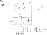
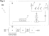
- FIG. 1 schematically shows a possible embodiment of a device Z according to the invention for emission-free generation of energy and / or hydrocarbons and methanol by utilization of carbonaceous materials, with a plant A for the thermal-chemical utilization of carbonaceous materials M10 to hydrocarbons and methanol M60 and / or liquid and / or gaseous fuels M61 (chemical energy), as well as for the generation of electrical and / or mechanical energy E1.
- the utilization plant A comprises a charging unit AH in which the raw material M10 to be recycled, which is still untreated, is prepared in carbonaceous starting material M11. Depending on the nature of the starting material M10, this may result in residues M17, which may be further usable, for example Metals.
- the core of the recycling plant A is the recycling unit AB, in which the treated carbonaceous materials M11 are supplied and pyrolyzed in a first subunit AC of a first process stage P1, pyrolysis coke M21 and pyrolysis gas M22 being formed.
- a second subunit AD of a second process stage P2 the pyrolysis coke M21 is gasified from the first process stage, resulting in synthesis gas M24, leaving behind slag and other residues M90.
- a third subunit AE of a third process stage P3 the synthesis gas M24 from the second process stage is converted into hydrocarbon-based solid, liquid and / or gaseous products M60, M61. All three process stages are pressure-tight closed and form a substantially closed circuit.
- Thermal energy accumulating in a recovery process according to the invention can be taken from the utilization unit AB in the form of steam M52 and used in an energy unit AF to generate electrical and / or mechanical energy E1 by means of a suitable drive device such as a steam turbine (not shown). Also possible and advantageous is the heating of compressible media, such as nitrogen, for operating the drive device. During a constant operation of the utilization unit AB, a certain basic output can thus be generated.
- the energy unit AF is an optional component of a device according to the invention.
- a discharge unit AG serves to discharge and treat the resulting ash and other solid residues M90.
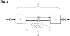
- the inventive device may further comprise an energy plant C, for the emission-free generation of electrical and / or mechanical energy E2, or thermal energy E4, by recycling the carbonaceous products M61 from the recycling plant A as operating materials. Resulting oxidizing gases M27 are returned to the recovery plant A, so that no emissions arise.
- the power plant C can be designed, for example, as a heating system for generating thermal energy E4 for heating buildings. Likewise, the power plant can be designed as an electric power plant for generating electrical energy E2.
- a plant B for the transport and the intermediate storage of the operating materials and oxidizing gases is advantageously switched on.
- Such a plant B may also contain means for the treatment of the inputs M61 for use in the power plant C.
- the hydrocarbonaceous fuels M61 produced in the synthesis process stage P3 are stored temporarily in tanks or pressure accumulators of the plant B (not shown).
- the supplies M61 are removed from these stores as needed, and converted into electrical and / or mechanical energy E2 in the energy system C with a suitable drive device. This can be done for example by means of a heat engine or a fuel cell device.
- Carbon dioxide-containing residual gas M26 from the energy plant C is returned to the recycling unit AB.
- a buffer may be provided.
- the energy system C offers the advantage that the energy output produced by the device Z according to the invention can be adapted in a very short time to the demand that is just required.
- the chemical consumables M61 serve as energy buffer.
- a suitably designed drive device for example a gas turbine and / or steam turbine operated with the operating fluids M61, can then be put into operation very quickly and generate electrical and / or mechanical energy. Due to the energy storage capacity of the chemical operating fluids M61, the peak power of the device Z can briefly exceed the basic thermal power of the device Z.
- the energy system C can be installed together with the recycling plant A at the same location.
- the power plant C is arranged spatially separated from the recycling plant A.
- the transport of the operating materials M61 and the oxidizing gases M27 can take place, for example, by rail, ship or pipeline, in which case the transport device (tank truck, tank on ship, pipeline) also serves as temporary storage BA, BB.
- the overall system of material transport between installations A and C should be considered in this case as part of Annex B for the transport and intermediate storage of fuels and oxidizing gases.
- the location of the peak-load power plant can be C of a device Z according to the invention are selected there where the corresponding requirement arises, while the recycling plant A is advantageously constructed where the carbonaceous starting materials M10 are produced.
- a device according to the invention can furthermore have a system D for the production and supply of external chemical energy.
- a system D for the production and supply of external chemical energy for example, hydrogen M32 can be produced and supplied as a source of external chemical energy.
- an inventive device Z is in the discussion of FIG. 6 will be discussed in more detail.
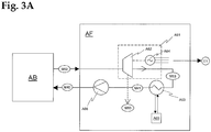
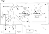
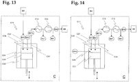
- FIG. 3 A possible embodiment of a recycling plant A of a device Z according to the invention is shown in FIG FIG. 3 shown schematically.
- the system A shown comprises a utilization unit AB for utilization of the carbonaceous starting material M11, and an energy unit AF for generating a substantially constant basic quantity E1 of electrical and / or mechanical energy.
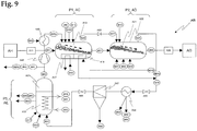
- the structure of the utilization unit AB essentially corresponds to the exemplary utilization unit which will be described later on the basis of FIG. 9 will be discussed.
- the base load energy unit AF is only shown as a block. One possible embodiment is in FIG. 3A be discussed.
- superheated steam M52 is produced from colder steam M51 (about 550-600 ° C / 50 bar). If necessary, a subsequent further heat exchanger can further cool the synthesis gas stream.
- the superheated steam M52 is fed into the energy unit AF, where it is utilized to electrical and / or mechanical energy E1.
- the remaining steam condensate M41 is returned to the recycling unit AB, where it is converted into steam M51 in the third process stage P3, and this steam M51 is subsequently converted again into superheated steam M52 in the heat exchanger / superheater A44.
- the exemplary embodiment of the energy unit AF in FIG. 3A comprises a drive device A61 in the form of a steam turbine A62 or another superheated steam steam engine M52 for generating mechanical energy, and in the example shown a generator driven by the steam turbine generator A64, which generates electrical energy E1.
- the exhaust steam M53 is condensed in the condenser / economizer A63, the waste heat being dissipated via a suitably designed cooling circuit A65.
- the resulting condensate M41 is preferably 60-70 ° C hot, so that the water in the subsequent boiler stage A32 of the recycling plant AB does not have to be heated too much. At the same time, the water should not be too hot to avoid cavitation in the A66 pump.
- the condensate M41 is conveyed by the pump A66 from a buffer (not shown) in the heat exchanger / boiler A32 process stage P3, where it is evaporated back to steam M51 (about 250-300 ° C / 20 bar), with simultaneous cooling the synthesis stage P3.
- the steam M51 is stored in a steam dome (not shown) to separate water remaining before entering the superheated A44, and to form a reservoir from which process steam M50 for the various purposes in the recovery unit AB can be taken , Losses in the circuit and consumption of process steam M50 are compensated by a new supply of water in the condensate tank (not shown).
- part of the steam can be taken off as process steam M50 in the steam turbine A62 after the high-pressure stage, which results in FIG. 3A shown as a dashed arrow is.
- process steam M50 in the steam turbine A62 after the high-pressure stage, which results in FIG. 3A shown as a dashed arrow is.
- the exhaust steam of process steam consumers such as the heat exchangers A45, A17 can also be condensed M41 and fed back into the feed water M40, so that as closed as possible energy cycle results.
- the steam cycles can also be conducted differently through the various heat exchangers in order to achieve the highest possible efficiency of the plant A.
- the products resulting from the synthesis stage P3 may be used as fuel M61 for a conventional fossil-fueled power plant C, for example diesel generators or gas turbine generators, which may be used to cover peak loads.
- the chemical consumables M61 serve, for a short time, to achieve very high production outputs, detached from the basic system AB, AF driven in an equilibrium state.
- the total output of the device Z may be increased from, for example, 100% constant base load production P c2 to, for example, 600% peak load production P e2 .
- the M60 products can also be used elsewhere, for example for the production of fuels or as educts for the chemical industry.
- such a device according to the invention has the advantage over conventional systems that flue gas filters and catalyst devices for purifying the combustion exhaust gases can be dispensed with in the utilization unit AB due to the closed matter flow within the three-stage process. This leads to a reduction of the number of components of such a system, and thus to lower investment costs and operating costs.
- such a utilization unit also has a smaller space requirement, since no filter systems, chimneys, etc. are required, and the volumes of the material streams are lower due to the high pressure.
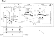
- a device Z according to the invention as shown schematically in FIG. 4 is disclosed, operated with supplies M61 from the recycling plant A power plant C is provided to cover peak loads E2.
- the energy system C is designed such that the carbon dioxide produced in the energy production is fed back into the circulation of the recycling plant A, so that no emissions arise.
- the supplies M61 are advantageously obtained from a buffer BA of the transport / storage plant B, for example, a tank system or a pressure accumulator to bridge demand peaks. Likewise, the resulting carbon dioxide-containing residual gases M26 from the energy system B can be collected and stored in a buffer BB.
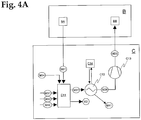
- a possible embodiment of an energy unit C is in FIG. 4A shown.
- a drive device C11 generates electrical and / or mechanical energy E2 by means of chemical energy carriers M61 from the synthesis stage P3 of the utilization unit AB.
- Said drive device C11 can be, for example, a heat engine in which the heat resulting from oxidation of the M61 to carbon dioxide is converted into mechanical work, for example for operation of a generator system (not shown), or a fuel cell system in which the oxidation reaction directly to Electricity generation E2 is used.
- Such a drive device C11 has a closed circuit, that is, it causes no emissions into the atmosphere.
- the resulting in the performance of the mechanical work of oxidizing gases M27, which contain essentially only carbon dioxide and optionally water, are treated C12, densified C13, and the remaining gas M26 fed back into the circulation of the recycling plant AB.
- a buffer BB is provided, as in FIG. 4 shown.
- the plant C of the device Z according to the invention can be arranged separately from the recycling plant A.
- the thermal or electrical energy generating oxidation reaction takes place in the drive device C11 with pure oxygen M31 instead of with air.
- oxygen M31 instead of air avoids the formation of nitrogen oxides due to the absence of atmospheric nitrogen in a thermal-chemical reaction at high temperatures, but above all substantially only carbon dioxide and water vapor remain in the resulting oxidation gases M27.
- the resulting gases may also contain certain proportions of carbon monoxide and unreacted fuel. These can easily be fed into the circulation of the recycling plant A.
- the reaction products M27 of the energy-generating oxidation reaction are substantially gaseous.
- the corresponding oxidizing gas mixture is now compressed C13 to reduce the volume.
- the oxidation gas mixture M27 can be cooled before and / or after the compression.
- Water M41 is condensed out and separated, leaving residual gas M26 only carbon dioxide, optionally with proportions of carbon monoxide and unreacted fuel.
- the residual gas M26 is now supplied to the first process stage P1 of the utilization unit AB of the plant A, so that there is a closed material cycle.
- the residual gas M26 can also be fed into the second process stage P2 or the third process stage P3, which is described in US Pat FIG. 4 indicated by dashed arrows.
- liquid or gaseous hydrocarbons and hydrocarbon derivatives can be produced from carbonaceous materials M11 in a device Z according to the invention, and the resultant high-quality fuel mixture M61 subsequently converted into electrical energy E2.
- the carbon dioxide produced is recycled and partially or completely converted into the recycling plant A back into M61. In this way, the effective carbon dioxide emissions of the peak load generator C can be greatly reduced or even completely avoided.
- the drive device can also be easily operated in combined operation with hydrogen M32 as further fuel.
- the hydrogen content leads to a reduction of accumulating residual gas amount M26 after the heat exchanger / condenser and compressor, since in the oxidation of hydrogen with oxygen only water is obtained.
- FIG. 5 Another advantageous embodiment of an inventive device Z is in FIG. 5 shown.
- this includes both a base load energy unit AF and a peak load power plant C.
- Molecular hydrogen M32 can be prepared by electrolysis of water, which also generates molecular oxygen M31. Electrical energy E3 can be converted into chemical energy in this way.
- the gaseous molecular hydrogen has a significantly lower energy density compared to liquid fuels, but also to gaseous hydrocarbons, so far it could not establish itself for use as a fuel for vehicles.
- the chemical energy of hydrogen can be efficiently converted into chemical energy in the form of high-quality hydrocarbons and other products. It is also advantageous to use the oxygen M31 obtained in the electrolysis in order to introduce the entire accumulating chemical energy into the process, or a maximum of the electrical energy inserted into the electrolysis.
- an installation D provides molecular hydrogen M32 and oxygen M31.
- the electrical energy E3 for the electrolysis reaction preferably originates from regenerative energy sources (wind power, solar energy, water energy, etc.). This has the great advantage that an inherent disadvantage of wind turbines DA and solar power plants DB can be overcome, namely the cyclical and due to the dependence on external factors not always guaranteed energy production. This leads to correspondingly low achievable market prices for the electrical energy generated.
- the generated energy output can be temporarily stored. Subsequently, the hydrogen, and if possible also the oxygen, is utilized in a process according to the invention in order, for example, to produce liquid contents which are easier to handle with higher energy density, or other high-quality products.
- the energy of the energy generating units DA, DB of the system D is transported as electric power E3 to the electrolysis unit DC, which is located at the location of the recycling plant A, and in which locally hydrogen M32 and oxygen M31 is generated. A part of the oxygen is not needed, and can be recycled elsewhere, for example in an energy plant C of the invention Device Z.
- Buffer units DE, DF for example in the form of pressure tanks, serve as buffers to compensate for the fluctuating energy production of the power generation units DA, DB.
- the recycling plant A produces high-quality hydrocarbons and other synthesis products M60, and optionally energy E1. Residues M90 are continuously removed from the system. It is also easy to remove water from the system, for example by condensation M41. In the illustrated embodiment, water is used primarily as an oxidizing and gasifying agent when no oxygen is available. However, water removed from the system M41 also serves as a sink for oxygen. This is particularly relevant if the system absorbs large amounts of carbon dioxide M33 as a carbon source.
- a recycling process according to the invention can also produce high-quality and high-energy hydrocarbon products M60 from comparatively low-energy carbon sources. in extreme cases, the process can in principle even be carried out exclusively with pure carbon dioxide as the carbon source. Since the supplied electrical energy comes directly or indirectly (wind power, hydroelectric power) from the sun, then results - seen from a fundamental point of view - quasi an artificial photosynthesis, namely the production of carbon compounds from carbon dioxide, water and sunlight.
- the combination of the recycling plant A with an energy plant C is optional.
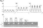
- FIG. 7 (a) schematically shows the performance profile of a conventional thermal power plant.
- the vertical axis represents the power P, and the horizontal axis the time t.
- the power plant has an added heat content P a , that is to say the heat energy or power contained in the fuel as chemical energy, and an effective thermal power P b , ie the heat energy which can be effectively converted into electrical or mechanical energy per unit time.
- P a the heat content
- P b effective thermal power
- the demand for electrical power P e in a conventional power grid varies both during the day and during the week.
- the overall rated power of such a power plant must be aligned with the peak load. This means that the dimensioning of the system is greater because of the required peak power than it would actually be necessary due to the average total power.
- Such a device Z as shown for example in FIG. 1 is shown, in the recycling plant A a constant part of the supplied in the form of the carbonaceous materials M10, M11 chemical energy into thermal energy in the form of water vapor, which is then converted, for example, with a steam turbine of the base load energy unit AF into electrical energy P f , Another portion of the chemical energy supplied in the form of the carbonaceous materials M10, M11 is converted in the synthesis stage P3 of the utilization unit AB with a constant production rate Pg into chemical energy in the form of high-grade carbonaceous materials M61, for example diesel-like products or gaseous products such as propane.
- These fuels can be stored in any amount BA, and / or as in FIG. 2 be transported carried over short or long distances.
- FIG. 7 (d) schematically shows the profile of the total power P e of a device according to the invention over the course of a week.
- the peak-load power plant C generates electrical energy from the chemical supplies M61 during the peak load demand during the working days, which can then be fed into a power grid at a correspondingly high price.
- the demand for chemical substances M61 substantially exceeds the production output P g of the recycling plant A, which is marked with (-). This above-average consumption is taken from the fuel storage BA.
- the demand drops sharply and the production output P g exceeds the demand P e , which is marked with (+).
- the fuel reservoir BA is replenished.
- the power plant C may be shut down to a minimum power level, as in FIG. 7 (d) is shown, or the power unit C is completely decommissioned, so that the base load P c is completely covered by the base load power unit AF.
- An inventive device thus has the significant advantage that only a portion P f of the constant effective power P d is obtained in the form of thermal power, which must be implemented as in a conventional power plant immediately in electrical and / or mechanical energy.
- This part P f can be used to deliver the power for the base load base P c .
- another part P g of the effective power P d is intermediately stored in the memory BA in the form of operating materials M61. The requirement (P e -P f ) exceeding the thermal power of the base load energy unit AF can then be covered by the peak load power plant C from the fuel storage BA.
- a device Z according to the invention can be designed with a much smaller installed thermal power in order to be able to cover a specific requirement profile, for example 75% or 50% of the thermal output of a comparable conventional power plant. This leads to significantly lower investment costs.
- a device according to the invention can be designed and optimized such that the power P f generated directly from thermal energy is reduced in favor of the power P g generated from the operating fluids M 61.
- Such a variant is in FIG. 7 (c) shown.
- Such an inventive device can cover a reduced base load base P c2 a much higher amount of energy to save. The corresponding stored energy can finally be used to generate peak load power P e2 , which can then be sold at a higher price.
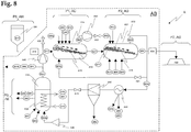
- FIG. 8 A first possible variant of a structure of a plant A for the thermal-chemical utilization of carbonaceous solids with a method according to the invention or in an inventive device is in FIG. 8 shown schematically.
- the recycling plant A of the device Z according to the invention comprises a utilization unit AB, with three subunits AC, AD, AE for carrying out the three process stages P1, P2, P3 of the inventive method, which are connected to a closed circuit, that they a closed, cyclic gas stream allow. From the processing unit AH, only the silo A91 is shown for providing the processed carbonaceous material M11. In turn, only the slag storage A92 is shown by the discharge unit AG.
- the recycling plant A may or may not include an energy unit (not shown). This is not relevant for the functionality of the recovery process.
- the three subunits AC, AD, AE of the utilization unit AB are connected to a closed circuit so that they allow a closed, cyclic gas flow.
- first process stage P1 pyrolysis stage
- first subunit AC carbonaceous starting material M11 is pyrolyzed under pressure, resulting in pyrolysis coke M21 and pyrolysis gases M22.
- second process stage P2 gasification stage
- second subunit AD pyrolysis M21 is gasified to synthesis gas M24, which finally in a third process stage P3 (synthesis stage) and the third subunit AE to hydrocarbons and / or solid, liquid , or gaseous products M60 is reacted.
- the carbonaceous starting materials M11 to be processed are continuously fed into the circuit via a feed device AH, P6 via the first process stage P1.
- the products M60, M61 produced from the synthesis gas M24 are withdrawn continuously from the third process stage P3.
- the various residues M91, M92, M93 are continuously removed from the circulation.
- the starting material M11 for a recovery process according to the invention can be a variety of carbonaceous materials, in particular waste, biomass, coal and other heterogeneous materials such as contaminated soil, but also already deposited waste, such as landfills. This allows the environmentally friendly and cost-effective dismantling of open landfills. Also difficult to use solid-liquid petroleum-containing materials such as oil shale, oil sands, or oil sludge can be utilized in a process according to the invention. As additives M12 carbon-containing by-products of the chemical or petroleum industry can be used, which otherwise can not be recycled and possibly even be flared.
- the calorific value of the starting materials, the carbon content, water content, and the content of non-combustible residues such as metal, glass and ceramic, can vary widely.
- the starting material can be comminuted to a size suitable for a particular recycling plant, the preferred piece size from the consistency of the material and from the specific design of the first pressure reactor or of the reactor-internal delivery system. For processing with a feed grate, for example, a piece size of about 5-10 cm is well suited.
- the first process stage P1, AC comprises a first pressure reactor A13 in which pyrolysis of the carbonaceous starting material M11 takes place under pressure.
- the starting material M11 is introduced via a suitable pressure lock A11 in the pressurized pyrolysis reactor A13.
- the pyrolysis reactor A13 consists of a horizontal pressure body A14 in which the horizontal conveyance of the lumpy material along the reactor during pyrolysis by a schematically illustrated feed grate A15 with reciprocating grate plates takes place.
- Any other conveying device suitable for the continuous feeding of the starting material to be processed is also applicable, for example roller grids, chain conveyors, screw conveyors, etc.
- a rotary kiln may also be used.
- the material is continuously transported at a temperature of about 300-800 ° C and a pressure of 1 to 60 bar through the pressure reactor A13 and thereby pyrolyzed under exclusion of oxygen.
- the temperature is chosen such that, in addition to maintaining the pyrolysis reaction, the desired operating pressure is maintained, firstly because of the expansion of the gases due to the temperature, and secondly because of the new production of pyrolysis gases.
- a minimum temperature of 450 ° C ensures a steady reaction of free oxygen compounds during pyrolysis.
- Particularly suitable are an operating temperature of 500-600 ° C and an operating pressure between 5 and 25 bar.
- process steam M50 serves to maintain the operating temperature of the first reactor.
- an external heat input such as a heat exchanger or an external heater. The latter is also advantageous when commissioning the recycling plant A from the cold state.
- Return gas M25 from the third process stage (synthesis stage) P3 is supplied to the first pressure reactor A13 after passing through a compressor A42.
- the return gas M25 mainly contains carbon dioxide, as well as water vapor and in the synthesis stage unreacted carbon monoxide and hydrogen, as well as residual contents of low molecular weight hydrocarbons.
- additional high calorific value carbon may be introduced into reactor A13, for example in the form of coal or heavy oil.
- additives M12 can be added in advance to the starting material M11, or be introduced separately into the reactor A13.
- the blending of M12 viscous additives with solid starting material M11 facilitates the transport of viscous material within the reactor. Liquid additives M12 also increase the amount of pyrolysis gas, and thus the operating pressure.
- Pyrolysis in the first process stage P1 produces pyrolysis coke M21, which consists essentially of solid carbon and inorganic residues.
- the pyrolysis M21 is discharged at the end of the pressure reactor A13.
- the pyrolysis gases M22 produced during pyrolysis contain both gaseous and solid materials which are liquid and solid at room temperature.
- the composition of the pyrolysis gases M22 naturally depends strongly on the starting materials, and optionally also contains pollutants.
- the pyrolysis coke M21 is conveyed under pressure into the pressure reactor A21 of the second process stage P2. Suitable again, for example, a closed auger. It can also be provided a pressure lock.
- the pyrolysis gases M22 are also conveyed via a separate transport line into the second pressure reactor A21.
- a compressor A41 arranged in the transport line conveys the pyrolysis gases into the second pressure reactor A21, which is under a higher operating pressure.
- the operating temperature is between 850 and 1600 ° C.
- the gasification of the solid carbon in the pyrolysis M21, with carbon dioxide and optionally oxygen and / or water vapor as a gasification agent to carbon monoxide and hydrogen, according to the reactions I, II and III now takes place.
- the carbon dioxide originates primarily from the return gas M25. Additional carbon dioxide M33 can also be added to the cycle.
- the water vapor consists primarily of the residual moisture of the starting material M11. It can also process steam M50 be fed.
- the thermal energy necessary for the course of these endothermic pyrolysis reactions originates for example from a partial oxidation of the solid carbon (reaction III) with oxygen M31 conducted into the second pressure reactor A21.
- the exothermic water gas shift reaction IV can also contribute to this.
- the ratio between carbon monoxide and hydrogen important for the later synthesis in the third process stage P3 is given by the water gas shift reaction IV, and can be influenced by adding process steam M50 to the right side. However, it is advantageous to measure the total amount To keep water in the system as low as possible, and instead introduce additional hydrogen M32 directly into the third process stage.
- the second process stage likewise comprises a pressure body A22, in which the conveying of the pyrolysis coke within the reactor A21 is effected by a feed grate A23.
- a pressure body A22 in which the conveying of the pyrolysis coke within the reactor A21 is effected by a feed grate A23.
- other delivery systems are possible, as they have already been discussed for the first pressure reactor A13. This has the advantage that the pyrolysis coke can be processed without further preparation in the second process stage.
- the second reactor can also be designed differently.
- the pyrolysis coke could be crushed or ground beforehand, which then permits gasification of the coke in the eddy current or flight stream.
- this variant has the disadvantage that the particles have a shorter retention time in the reactor, which requires a more homogeneous material supply and treatment.
- such systems require more precise and faster control of the gas flow rate and other process parameters.
- the reactive surface area of particulate pyrolysis coke is comparatively small in comparison to a likewise possible reaction in the eddy current, but this is compensated by the comparatively long residence time in reactor A21 due to the high mass capacity of the pressure reactor.
- Another advantage is the easier scalability. By a simple extension of the pressure reactor or a Enlarging the cross-section can increase the capacity and thus the turnover, without the relevant process parameters such as pressure or temperature having to change. In contrast, reactors with flying or eddy currents can not be scaled up so easily and without problems.
- the necessary for the partial oxidation of oxygen M31 and optionally the process steam M50 is injected into the ember bed formed by the pyrolysis, whereby the necessary thermal energy is generated and the reactor A21 is kept at operating temperature.
- air could also be used, but the inert nitrogen of the air inflates the gas material flow circulating within the utilization unit, and is difficult to remove again. This significantly reduces the efficiency of the plant, so that pure oxygen is preferable in any case.
- the absence of nitrogen in the system also prevents the formation of nitrogen oxides.
- the pyrolysis gases M22 are in the in FIG. 8 shown embodiment of a recovery plant A blown into the gas phase above the ember bed in the pressure reactor A21, where the polyatomic molecules contained in the pyrolysis gases M22 are cracked very rapidly and decomposed at the prevailing high temperatures.
- the synthesis gas M24 formed in the second process stage therefore contains essentially no more organic molecules, and can be used for the Fischer-Tropsch synthesis in the third process stage. Pollutants such as dioxin are also decomposed.
- the oxygen feed M31 into the ember bed and the entry point of the pyrolysis gases M22 into the pressure reactor are advantageously chosen so that no formation of dioxins can take place, which can be achieved by a suitable spatial separation. Likewise, there should be no oxygen in the exiting syngas.
- residues M91 remain in the form of ash and inert residues and optionally unprocessed carbon. If slagging is desired, additives can be added which lower the ash melting point. For this purpose, for example, lime powder can be added to the starting material M11. The slag is discharged from the second pressure reactor A21 via a suitable pressure lock A28 from the pressure range of the recycling plant AB.
- the second process stage can alternatively be designed so that unreacted pyrolysis coke is again conveyed to the beginning at the end of the pressure reactor, and thus can pass through the reactor a second time. This allows a shorter design of the pressure reactor.
- the synthesis gas stream M24 is discharged from the second pressure reactor A21, and a main part M24a is passed through a suitable heat exchanger A44, where the gas stream to produce, for example, process steam M50 for in-process purposes and / or steam M52 for energy in an energy unit AF (not shown) is cooled to a temperature suitable for the Fischer-Tropsch synthesis in the third process stage P3. Due to the lower temperatures, the pressure drops and shifts the balance of the reactions I, II and IV, whereby the proportion of carbon dioxide in the synthesis gas increases again. Also, solid carbon M94 in the form of graphite can be separated from the gas stream. The carbon M94 can be used as starting material M11, M12 back in be recycled, recycled as recyclable material, or removed as a residue from the system.
- the synthesis gas stream M24a is fed to a cyclone A47, where dust M92, mainly consisting of residual coke and ash, is separated off.
- the residual dust M92 can be returned to the first pressure reactor A13 or second pressure reactor A21, or it is recycled and / or disposed of.
- a cyclone another suitable gas flow cleaning device may be used.
- the carbon M94 passes with the synthesis gas stream in the Fischer-Tropsch reactor A31, where it can be precipitated or filtered off together with the by-produced carbon in the Fischer-Tropsch reaction.
- a gas stream preparation may further be provided in order to remove interfering substances in the synthesis gas.
- residues are advantageously removed, which are disadvantageous for the subsequent synthesis stage.
- sulfur compounds can act as a catalyst poison in the Fischer-Tropsch synthesis.
- the synthesis gas M24 is now fed via a pressure regulator A48 to a third pressure reactor A31 of the third process stage P3, in which a Fischer-Tropsch synthesis is carried out.
- the pressure regulator A48 reduces the pressure to the value desired for the third process stage.
- additional hydrogen M32 can be passed into the Fischer-Tropsch reactor A31.
- the necessary solid state catalysts M37 are supplied.
- the carbon monoxide and the hydrogen react strongly exothermic (about 158 kJ / mol per hydrocarbon chain member at 250 ° C) of heterogeneous catalysts (for example, iron, cobalt, ruthenium, nickel catalysts) to alkanes , Olefins, alcohols, aldehydes and other hydrocarbon compounds and derivatives.
- heterogeneous catalysts for example, iron, cobalt, ruthenium, nickel catalysts
- By-products are methane and solid carbon, which are also formed in strongly exothermic reactions.
- the precise parameters of the Fischer-Tropsch synthesis, in particular pressure and temperature depend primarily on the products to be produced, and are not directly relevant to the basic functional principle of a device according to the invention or the method according to the invention. Higher process temperatures tend to result in shorter chain lengths and increased carbon capture, while higher pressures result in longer chain lengths.
- especially the present partial pressures of carbon monoxide, hydrogen and water have a strong influence on the synthesis products.
- Suitable for the synthesis stage are, for example, low-temperature Fischer-Tropsch process, which are operated for example at 210 to 250 ° C, and especially diesel-like products and long-chain portions in the form of waxes. The latter can then be further utilized, for example by hydrocracking.
- High-temperature processes with temperatures between 320 and 350 ° C, in turn, provide significant proportions of methane, short-chain alkanes and alkenes, as well as higher levels of light gasoline.
- For low temperature processes are, for example, tube bundle reactors in which the synthesis gas flows through catalyst-filled, cooled tubes from top to bottom. Return gas and products leave the tube at the bottom.
- Suspensation reactors have a simpler construction than tube bundle reactors, and are therefore more cost effective.
- the catalyst can be used more efficiently, and is exchangeable during operation, which is advantageous in the cyclic method according to the invention. Furthermore, such a method has the advantage that the heterogeneous catalyst can be continuously regenerated by mechanical exposure of new, unused surfaces of the catalyst particles during the circulation. In this way, a sulfur poisoning of the catalyst can be continuously compensated. As a result, sulfur removal from the syngas stream may be unnecessary.
- the steam M51, M50 obtained by the cooling device A32 contains considerable thermal energy, but is not yet hot enough for efficient utilization, for example, in a steam turbine of an energy unit AF. It is therefore used advantageously for hot steam production M52, for example in heat exchanger A44, in order to increase the overall energy efficiency of the plant.
- a utilization unit AB and another, energy-generating unit AF of a recycling plant A is already in the FIGS. 3 to 5 been received.
- the gas stream M25 leaving the Fischer-Tropsch reactor A31 contains, in addition to unreacted carbon monoxide and hydrogen gas, also steam, carbon dioxide, and gaseous reaction products M60.
- a proportion of volatile hydrocarbons M60 can be condensed therefrom, for example, with the aid of a cooling column (not shown).
- water M41 can be condensed out and thus removed from the return gas and thus from the matter flow.
- From the remaining recycle gas stream part M25b can be separated as a process product.
- the remaining recycle gas stream M25a is compressed in a compressor A42 and returned to the first reactor A13.
- the cyclical promotion of the gas flow within the recovery plant A is mainly due to the prevailing pressure differentials along the cycle. These are primarily generated by the two compressors A41, A42. Depending on the design of the system, one of the two compressors can be dispensed with, which reduces the overall costs of the system. Does the plant only a compressor (such as in the second embodiment of a recycling plant in FIG. 9 ), the arrangement in front of the first reactor A13 has the advantage that the corresponding compressor A42 must compress a smaller gas volume than a compressor A41 between the first and second process stage, where in addition the pyrolysis gases are added and the total volume is greater due to the higher temperature , or even between the second and third process stage.
- the compressor A41 If the compressor A41 is dispensed with, then there is only a slight pressure gradient between the two reactors A13, A21, so that the first and second process stages take place essentially at the same pressure.
- the gas stream then flows from the compressor A42 via the first A13, second A21 and third reactor A31 back to the compressor A42.
- the compressor A42 when the compressor A42 is omitted, the pressure within the third reactor A31 and the first reactor A13 is substantially equal. It is also possible to arrange a compressor between the second and the third process stage. For entropy reasons, at least one compressor or other conveyor must be present to promote the gas flow and keep the process running.
- accumulators may be provided along gas cycle M22, M24, M25 (not shown). Analogously, it is also possible to provide a buffer for the pyrolysis M21.
- the compressor A41 can produce a pressure difference of several bar with reasonable energy expenditure.
- the first process stage could then be run at a much lower pressure than the second process stage.
- the first process stage can even be carried out at atmospheric pressure or even underpressure.
- the circulation and the three process stages are flushed and filled with an oxygen-free gas, advantageously with carbon dioxide and / or carbon monoxide and / or hydrogen gas or mixtures thereof, ie synthesis gas.
- an oxygen-free gas advantageously with carbon dioxide and / or carbon monoxide and / or hydrogen gas or mixtures thereof, ie synthesis gas.
- the previously pressurized with coke second pressure reactor A21 is heated, for example with gas burners.
- the second reactor is separated from the circuit, by closing the corresponding compounds.
- the feed A23 of the coke within the pressure reactor A21 is not yet switched on.
- a temporary short circuit between heat exchanger A44 and pressure reactor A21 may be provided in the circuit (not shown) in order to circulate the heated gas in the system and to heat the entire system section evenly.
- the pressure is also increased to the setpoint.
- the first pressure reactor A13 also previously filled with coke, is separated from the circuit and heated to the envisaged operating temperature of the first process stage.
- the pressure is also brought to the desired value for the first process stage.
- the material feed A15 in the first reactor is still switched off.
- the heating should preferably be done without starting material, as pyrolysis of the starting material below a minimum safe operating temperature of 450 ° C can lead to the formation of explosive mixtures.
- the coke on the other hand, is already pyrolyzed, and serves only to supply coke to the second stage of the process when the cycle is started later.
- the Fischer-Tropsch reactor A31 is also disconnected from the circuit raised to the operating conditions. After reaching the operating conditions in the various process stages of the recycling plant, the various conveyor systems A15, A23 are slowly started up, opened the circuit, and the compressor A41, A42 put into operation, so that ultimately an equilibrium state of the recycling plant AB results in the desired operating parameters.
- FIG. 9 A further embodiment of a utilization unit AB of a device Z according to the invention is shown in FIG. 9 shown. On the representation of the limit of the utilization unit AB has been omitted for clarity.
- the branched synthesis gas stream M24b is not passed directly back into the first reactor A13, but instead passed through a heater A16 of the pressure reactor A13 and then reunited with the synthesis gas M24a.
- a further heating device A17 can be provided, which is operated with process steam M50.
- a heat exchanger A45 is disposed in the recycle gas flow M25a and serves to heat the recycle gas flow M25a through process steam M50.
- the return gas flow in this embodiment thus also serves to supply heat to the first pressure reactor A13.
- no pressure reduction is provided before the third pressure reactor A31.
- the pressure control in the third process stage is carried out directly via the pressure control in the second process stage and the subsequent pressure drop due to the cooling of the synthesis gas stream M24 in the heat exchanger A44, and the compressor A42.
- the low-temperature Fischer-Tropsch reactor of the third process stage is replaced by a high-temperature Fischer-Tropsch reactor in which the catalyst is present as turbulent flue dust.
- the gaseous, short-chain hydrocarbons preferably formed in the high-temperature Fischer-Tropsch synthesis, which remain in the recycle gas after a first condensation stage, are separated from the smaller molecules of the recycle gas such as carbon dioxide, carbon monoxide, hydrogen by permeation gas filters.
- Such systems are known for example from the petrochemical industry for the purification of natural gas. In the present case, they serve to generate a first, hydrocarbon-rich gas phase and a second, low-hydrocarbon gas phase.
- the hydrocarbon-rich gas phase is further utilized as fuel for a second generator stage for generating electrical energy, or is processed into liquefied petroleum gas and natural gas.
- the low-hydrocarbon and carbon dioxide-rich second gas phase is sent back into the circulation as recycle gas.
- the third process stage P3 comprises a liquid phase methanol synthesis reactor instead of a Fischer-Tropsch reactor.
- the known from the prior art liquid-phase methanol synthesis is particularly suitable to produce methanol in high yield from synthesis gas with a higher proportion of carbon dioxide.
- the synthesis takes place in a "slurry bubble column reactor" in which the synthesis gas is injected into a slurry of the powdered catalyst in an inert mineral oil. The reaction is highly exothermic, so a cooling device is necessary.
- the generated gaseous methanol leaves the pressure reactor together with unreacted synthesis gas. After separation of entrained mineral oil and catalyst, the methanol is condensed out.
- Methanol is a valuable base product for the chemical industry, and can also be used as a fuel. Methanol can also serve as an additive to gasoline, for example, in Germany, a share of up to 3% methanol in vehicle gasoline is allowed. The methanol can also be used in particular as a fuel M60 for a second generator stage.
- FIGS. 8 and 9 represented inventive method is based on a cyclic material flow through the three process stages P1, P2, P3 of the utilization unit AB, wherein carbonaceous Starting material M11 fed as a carbon supplier and energy sources in the cycle and diverted the products of the synthesis stage as recyclables M60 or as supplies M61 for the power plant C of the inventive device.
- the slag M91 and other residual materials M92, M93, M94, as well as water vapor in the recycle gas M25 are continuously removed from the circulation.
- the steam produced in the heat exchangers is used as process steam M50 for the operation of the plant, thus increasing the efficiency and effectiveness of the plant.
- the hot steam M51, M52 can be used for energy production in an energy unit AF.
- a high-energy product M60, M61 is produced from a high-energy but heterogeneous and difficult-to-use solid starting material M11, namely the various fractions of the Fischer-Tropsch stage. These can then be further utilized, for example as liquid fuels or as educts for the chemical industry.
- the energy required for the operation of the recycling plant AB comes from the partial oxidation reaction in the second process stage, wherein an excess of the chemical energy generated there (in the form of the synthesis gas) later in the exothermic Fischer-Tropsch reaction of the third process stage back into thermal energy Form of steam M50, M51 is converted.
- superheated steam M52 for continuous operation of a base load energy unit AF is generated from the carbonaceous starting material M11 and also fuel M61 for flexible operation of a peak load power unit C.
- the pressure and the temperature in the third reactor A31 are the decisive parameters.
- the pressure can be controlled at short notice with the compressor A42 by increasing or decreasing its capacity.
- the temperature can in turn be controlled by the cooling capacity of the heat exchanger A32.
- the pressure can be controlled by the pressure in the synthesis gas stream M24 by changing the operating pressure and the temperature in the second process stage, and by controlling the cooling capacity of the heat exchanger A44, and thus the temperature and pressure drop in the synthesis gas stream M24.
- the control of a recycling plant A is comparatively simple because the plant is in a state of equilibrium with feedback, and to control a few relevant parameters a plurality of parameters, the individual operating parameters of the various plant components can be changed, which can affect the balance slowly or quickly.
- the utilization process according to the invention is preferably carried out with an increased carbon dioxide content. This shifts, among other things, the reaction equilibrium IV to the left (more carbon monoxide). Such an increased carbon dioxide content is made possible while at the same time still the highest possible absolute amounts of carbon monoxide and thus processing power through the increased operating pressure of the recovery plant between 10 and 60 bar. Higher or lower pressures are also possible, but less efficient.
- the recycling plant can be optimized with regard to various aspects. If, for example, particularly carbon dioxide-neutral biomass such as wood chips in the third process stage recyclable materials such as diesel and benzine analogous hydrocarbons and waxes, etc. are produced, the process is on the best possible balance between the cost of biomass and the current Operation and the value of the generated recyclables. On the other hand, less carbon dioxide has to be taken into account, since it is carbon dioxide-neutral biomass. In order to further improve the ecological balance, the external energy supply (electric current, etc.) can be reduced, with possibly increased biomass consumption.
- the plant is operated in such a way that as little carbon dioxide as possible is removed from the cycle and released into the environment. This then possibly leads to an increased demand for external energy.
- the utilization plant can be optimized for maximum throughput of starting material, so that optionally unprocessed pyrolysis coke leaves the third process stage together with the slag.
- the environmental problematic little pyrolysis coke can then be deposited together with the slag.
- Such a variant is advantageous, for example, when large amounts of contaminated material are to be rendered harmless to carbon dioxide neutral.
- the operating temperature of the second process stage P2 can also be optimized.
- the operating temperature of the second process stage P1 of the utilization unit AB can be lowered in order to increase the throughput in the second reactor A21. This then possibly leads to the fact that certain volatiles are no longer cracked in the pyrolysis M22 and get into the Fischer-Tropsch reactor A31 with the synthesis gas M24.
- benzene can be obtained from the starting material, for example from heavy oil, in smaller quantities in the products of the Fischer-Tropsch synthesis. There, these materials remain as part of a liquid fuel M61, but if necessary, can also be separated.
- FIG. 10 schematically shows an advantageous embodiment of a recycling unit AB.
- a heat exchanger A46 is arranged, which serves to heat the pyrolysis gases M22 to the operating temperature of the second process stage before entering the second pressure reactor A21 with process steam M50. It is also possible to feed the heat exchanger A46 with hot synthesis gas M24.
- the compressor A43 is arranged in the transport line of the synthesis gas M24, after a heat exchanger A44. Although the mass flow at this point of the system is greatest, due to the greatly lowered temperature after the heat exchanger A44, the volume of gas to be handled for the compressor A43 is smaller, and the operating temperature for the compressor is lower there.
- FIG. 11 A further advantageous embodiment of a utilization unit AB of a disclosed device Z is shown in FIG. 11 which is particularly suitable for the production of liquid inputs M61 from unloaded biomass such as wood chips.
- the pyrolysis gases M22 are not passed into the second process stage P2 but in the third process stage P3, the synthesis gas M24 not in the third process stage P3 but in the first process stage P1, and the return gas M25 not in the first process stage P1 but in the second process stage P2.
- the hot synthesis gas stream M24 heats the pyrolysis product and maintains the operating temperature.
- the pyrolysis gas stream M22 emerging from the first process stage then contains not only the actual pyrolysis gases but also the synthesis gas fraction from the second process stage, which therefore makes a loop here via the first process stage.
- the proportion of synthesis gas in the pyrolysis gases M22 is reacted, while those pyrolysis gas components which do not already condense out in the heat exchanger A45 M23 dissolve in the liquid phase of the synthesis reactor A31. Since in a direct use of the products M60 of the third process stage as fuel or as fuel for the second drive device C11, the purity requirements are not particularly great, can be dispensed with cracking of the pyrolysis gases.
- the fuel M61 is then post-cleaned to remove unsuitable residues such as organic acids, etc.
- the condensed out fractions M23 of the pyrolysis gas which have a low melting point and boiling point and contain a considerable proportion of tar, can advantageously be supplied as solid or liquid aggregate M23 of the second process stage.
- the recycle gas stream M25 is then compressed A42, heated A46 and introduced into the second process stage P2, so that a cycle is formed again. Since cracking of the gases introduced into the pressure reactor A21 is not necessary, the second process stage can be run at a lower operating temperature.
- FIG. 12 shows an embodiment of a utilization unit AB, in which the first and the second process stage P1, P2 are performed in a common pressure reactor A24.
- the pyrolysis takes place in a first chamber A25 of the reactor A24, the gasification in a second chamber A26.
- the two chambers A25, A26 are formed by a separating wall A27 arranged in pressure reactor A24, with a passage through which a common conveying system conveys the pyrolysis coke M21 and the pyrolysis gas M22 flows.
- the partition wall A27 serves primarily to thermally isolate the two chambers A27, A26, so that in the two process stages different operating temperatures can be driven. It is also possible to equip such a common pressure reactor with more than two separate chambers.
- a drive device C11 of an energy system C of a device according to the invention is designed as an internal combustion engine
- water M40 can be used as an additional expansion agent.
- a certain amount of water is injected into the cylinder after the ignition of the combustion process, for example after the auto-ignition of the compressed fuel-air mixture in a diesel engine.
- This water which is preferably finely atomized, is then evaporated by the heat energy of the exothermic oxidation reaction.
- the resulting gas pressure or gas volume increase due to the water vapor thus contributes to the generation of kinetic energy, but at the same time the temperature of the total mixture of combustion exhaust gases and water vapor decreases.
- this is not a problem or even desirable, because due to the higher energy density of a reaction with pure oxygen much higher reaction temperatures arise, which improves the thermodynamic efficiency, but can also load the parts of the drive device C11 more.
- the water can also be introduced as steam M50.
- a certain proportion of liquid water can also be supplied mixed with the liquid fuel.
- superheated steam also acts as an additional oxidant besides oxygen.
- FIG. 13 the operation of such a possible drive device C11 for a peak load power plant C of a device Z according to the invention is described and explained in more detail, using the example of an internal combustion engine in the form of a piston engine with a cylinder.
- drive devices C11 designed as internal combustion engines can also be designed as turbines or Wankel engines, etc.
- the hot combustion gases are used according to the principle of operation of the respective type of internal combustion engine for the performance of mechanical work, for example, to operate a generator system, and thereby partially relaxed. Subsequently, the oxidation gas M27 leaves the combustion chamber.
- the combustion gas mixture M27 is expelled from the cylinder at the third stroke, and then compressed and cooled.
- a drive device C11 as a heat engine with external combustion, for example as a steam engine or steam turbine.
- internal combustion engine C11 has a cylinder C22 and a movably arranged piston C23, which together form a closed combustion chamber C21.
- a feed device C27 shown only schematically, oxygen M31 is introduced into the expanding combustion chamber C21 in a first cycle. Subsequently, in a second cycle, the oxygen M31 is compressed, and at the end of the second cycle with a supply device C29 the fuel M61 is introduced into the combustion chamber C21 and burned.
- the expanding combustion gases M27 perform mechanical work, and at the fourth cycle, the partially expanded combustion gases M27 are discharged from the combustion chamber C21 through a venting device C24, not shown.
- the hot oxidation gases M27 which consist essentially only of carbon dioxide and water vapor, are then cooled in a downstream heat exchanger C12. This reduces the volume of these oxidizing gases M27. As a result of the cooling, most of the water M41 condenses and is separated off.
- the remaining residual gas M26 which consists essentially only of carbon dioxide and optionally residual amounts of carbon monoxide and unreacted operating materials, is compressed in a compressor C13 arranged in series and collected in a pressure accumulator BB.
- the condensation stage C12 before compression reduces the unwanted formation of condensate droplets in the compressor C13.
- the illustrated internal combustion engine C11 has no emissions. Since the device is not operated with air or similar gas mixtures as the oxidant, no air-specific pollutants such as nitrogen oxides can arise. The water produced during combustion is unproblematic and can be separated. The carbon dioxide is used as residual gas M26 in led the cycle of recycling plant AB. Unburned portions of the fuel either condense with the water and are separated or are compressed together with the carbon dioxide. The oxidizing gases M27 from the drive device C11 can also be passed without cooling directly into the first or second process stage.
- the peak load energy unit C spatially separated from the recycling plant A, and a direct return of the residual gases M26 is not practical, they can also be very compacted and transported under high pressure in pressure accumulators BB from the power plant C to recycling plant A.
- FIG. 14 A further possible embodiment of a drive device C11 designed as an internal combustion engine is shown schematically in FIG. 14 shown.
- water M40 is introduced into the combustion chamber C21 through a feed device C28 shown only schematically. This is preferably done so that during or after the combustion reaction, a certain amount of water, liquid or vapor, is injected into the combustion chamber C21 and finely distributed. This water is heated by the heat of combustion, whereby the total gas volume in the combustion chamber C21 increases, and thus also the gas pressure or gas volume available for the performance of the mechanical work. Accordingly, the amount of fuel can then be reduced while maintaining the same performance.
- water M40 can also be introduced into the oxidation gas stream M27 when it has left the combustion chamber C21.
- Such a variant has the advantage that the combustion reaction in the combustion chamber can run efficiently at the highest possible temperatures, and at the same time the resulting temperature of the oxidizing gas flow is so low that the downstream devices C12, C13 are less stressed.
- the amount of water and the timing of the injection are matched with the supply of fuel M61 and oxygen M31 so that the combustion reaction can take place efficiently.
- the resulting temperature during the oxidation reaction is substantially such that the highest possible thermodynamic efficiency of the heat engine is achieved.
- the greater the amount of water used the lower the relative proportion of carbon dioxide in the reaction gases, which reduces the amount of residual gas M26 remaining after the condensation of the water M41.
- the oxidation gases M27 are first compressed in a compressor C13 before they are subsequently cooled in the heat exchanger C12.
- This variant is also with the internal combustion engine C11 without water injection off FIG. 13 combinable, and vice versa, and can generally be used for a drive device C11.
- the energy required for the operation of the compressor of a drive device C11 is advantageously generated by the drive device itself.
- the achievable efficiency of the drive device decreases, but at the same time the freedom from emissions of said drive device is achieved.
- the achievable performance with the same engine dimensioning is greater, which compensates for the loss of power again.
- the compressor can be operated for example via a suitable transmission directly to the crankshaft of a piston internal combustion engine.
- the compressor can sit directly on the same shaft.
- the oxidation gases can then be condensed directly subsequent to the expansion process and the remaining flow stream can be compressed.
- the oxidation gases are already precompressed after combustion at the third cycle within the combustion chamber, and only then discharged through the venting device C24.
- the downstream compressor C13 can also be omitted.
- Such an embodiment is also possible as a two-stroke variant, because the new loading of the combustion chamber with reaction mixture (fuel M61, oxygen M31, water M40) can be done very quickly in a drive device.
- reaction mixture fuel M61, oxygen M31, water M40
- the combustion gases are precompressed and exhausted from the combustor towards the end of the cycle.
- the gaseous oxygen may be injected into the combustion chamber under high pressure at the end of the upstroke because comparatively little oxygen is needed for a complete combustion reaction and water is present as an additional expansion agent.
- the liquid fuel M61 and the water M40 as expansion agent can be injected anyway very quickly and under high pressure in the combustion chamber C21.
- the energy consumption for the compressor C13 can be optimized by a suitable combination with one or more heat exchangers or cooling elements, in which the gas volume can be reduced by emitting heat energy of the reaction gases to an internal or external heat sink.
- steam can be generated, which can either serve to increase the efficiency of an energy unit AF of the recycling plant, or for obtaining process steam M50 for the operation of the recycling unit AB of the recycling plant.
- FIG. 15 shows a particularly advantageous embodiment of a peak load power plant C, with a drive device C11, which is designed as a combined gas / steam turbine.
- a drive device C11 which is designed as a combined gas / steam turbine.
- fuel M61 is burned with oxygen M31 in a burner C25 to form a very hot combustion gas.
- Water is introduced into the combustion chamber C21, preferably as superheated liquid water having a temperature of for example 250 ° C. and a pressure of 50 bar.
- the resulting water vapor mixes with the combustion exhaust gases to produce a hot (eg, 600 ° C) oxidizing gas M27a with a high level of superheated steam exiting the combustor C21 and being converted to mechanical work in a subsequent turbine apparatus C30, with which in turn, a generator device C31 is driven.
- a hot (eg, 600 ° C) oxidizing gas M27a with a high level of superheated steam exiting the combustor C21 and being converted to mechanical
- the gas mixture in the combustion chamber isochronous, so that the gas pressure increases, or isobaric, so that the gas volume increases accordingly, or both the volume and the pressure rise.
- the subsequent turbine device C30 must be configured. Suitable turbines C30 are known from the prior art, and usually have several process stages. In an alternative variant, after a high-pressure stage of the turbine device C30, partially expanded process steam M50 can be drawn off and used elsewhere.
- the expanded oxidizing gas M27b is passed into a condenser / economizer C12, where the water M41 is condensed out and separated.
- the remaining residual gas M26 which essentially contains carbon dioxide, is compressed in a compressor C13 and conveyed to the first process stage P1 of a recycling plant AB.
- the compressor C13 is advantageously driven directly via the turbine C30.
- the water M40 can also be mixed with the oxidation gas stream M27a only subsequently to the combustion chamber C21, for example by means of a Venturi nozzle.
- the amount of water M40 and the amount of fuel mixture M61, M31 and the other selectable parameters are advantageously coordinated so that the subsequent turbine achieves the highest possible energy utilization.
- the proportion of water in the oxidizing gas mixture M27b should be as high as possible.
- the highest possible pressure drop of the gas mixture on the condenser C12 is achieved, which increases the total pressure difference across the turbine C30, and thus its efficiency.
- Another advantage of introducing steam into the combustion chamber is the cooling effect of the M50 steam.
- the exothermic oxidation of the fuel mixture M61, M31 can lead to very high temperatures of up to 1000 ° C or even 2000 ° C. Such temperatures would greatly stress the structures of the combustor C21 and the subsequent turbine apparatus C30.
- the comparatively cold water vapor is preferably introduced into the chamber in such a way that it shields the walls of the combustion chamber C21 from the very hot flame C26.
- the steam finally cools the entire gas mixture to 600 ° C to 800 ° C, which reduces the thermal load on the turbine blades and correspondingly increases the service life.
- the illustrated drive device differs, for example, from a conventional gas turbine also in that the combustion chamber is preceded by no compressor.
- This allows a much simpler design of the combustion chamber C21 than in a gas turbine. Since the M61 consumables are burned with pure M31 oxygen, the energy density achievable is higher than when using air with its reduced oxygen content. Nevertheless, in order to increase the amount of oxygen that can be introduced into the combustion chamber C21 per unit of time, it can be pressurized in advance.
- the turbine apparatus C30 may be configured like a steam turbine because the temperature and pressure ranges of the oxidant gas M27a are substantially the same.
- the drive device C11 can also be permanently in operation, for example at 10% to 50% of the power of the base load generator system AF. When increasing the power demand then the system C can be brought to maximum power in a very short time, for example, 500% of the power of the base load generator system AF.
- a device Z according to the invention can very dynamically adjust the overall performance over a wide range.
- a peak load power unit C may also include a plurality of combustors C21 and / or turbine devices C30.
- the individual parts of the system are dimensioned and designed so that they can be efficiently broken down into individual modules, which are transported by truck and then reassembled can.
- Particularly advantageous is a maximum dimensioning of the modules, which allows transport without special means of transport.
- Such a modular device according to the invention has the advantage that it can also be created only temporarily, for example for an operating period of only a few years or even only months. Once there is no need anymore, it can be disassembled and rebuilt at a new location.
- Such a device is particularly useful in mining, for example, when in remote mining areas a larger energy infrastructure has to be set up in a short time, which is no longer needed after the end of the mining activities.
- a recycling plant of a device according to the invention can be used to produce diesel fuel for vehicles and power generators of a remote Tagbaumine from locally grown biomass and carbonaceous waste materials, and / or electrical energy for the operation of the infrastructure.
- the reactors of the first and second process stage can be constructed as horizontal reactors with a comparatively small cross-section without the throughput being reduced.
- the reactor is simply lengthened accordingly in the longitudinal direction.
- the reactor can then be built in the longitudinal direction of several flanged modules together.
- the synthesis reactor can be scaled by using multiple reactors operating in parallel.
Landscapes
- Chemical & Material Sciences (AREA)
- Engineering & Computer Science (AREA)
- Organic Chemistry (AREA)
- Combustion & Propulsion (AREA)
- Oil, Petroleum & Natural Gas (AREA)
- Mechanical Engineering (AREA)
- General Engineering & Computer Science (AREA)
- General Chemical & Material Sciences (AREA)
- Chemical Kinetics & Catalysis (AREA)
- Engine Equipment That Uses Special Cycles (AREA)
- Carbon And Carbon Compounds (AREA)
- Production Of Liquid Hydrocarbon Mixture For Refining Petroleum (AREA)
- Organic Low-Molecular-Weight Compounds And Preparation Thereof (AREA)
- Luminescent Compositions (AREA)
- Hydrogen, Water And Hydrids (AREA)
- Processing Of Solid Wastes (AREA)
- Coke Industry (AREA)
Priority Applications (8)
| Application Number | Priority Date | Filing Date | Title |
|---|---|---|---|
| SI201031947T SI2501786T1 (sl) | 2009-11-20 | 2010-11-19 | Toplotno-kemično izkoriščanje materialov, ki vsebujejo ogljik, zlasti za pridobivanje energije brez emisij |
| RS20191418A RS59514B1 (sr) | 2009-11-20 | 2010-11-19 | Toplotno i hemijsko iskorišćavanje ugljeničnih materijala, naročito za bezemisionu proizvodnju energije |
| EP19190005.9A EP3594313A1 (de) | 2009-11-20 | 2010-11-19 | Thermisch-chemische verwertung von kohlenstoffhaltigen materialien, insbesondere zur emissionsfreien erzeugung von energie |
| EP10777041.4A EP2501786B1 (de) | 2009-11-20 | 2010-11-19 | Thermisch-chemische verwertung von kohlenstoffhaltigen materialien, insbesondere zur emissionsfreien erzeugung von energie |
| PL10777041T PL2501786T3 (pl) | 2009-11-20 | 2010-11-19 | Termiczno-chemiczne użytkowanie materiałów zawierających węgiel, w szczególności do bezemisyjnego wytwarzania energii |
| MEP-2019-308A ME03549B (me) | 2009-11-20 | 2010-11-19 | Toplotno i hemijsko iskorišćavanje ugljeničnih materijala, naročiтo za bezemisionu proizvodnju energije |
| HRP20191988TT HRP20191988T1 (hr) | 2009-11-20 | 2019-11-04 | Termokemijska upotreba materijala koji sadrže ugljik, osobito kod proizvodnje energije bez emisije |
| CY20191101158T CY1122410T1 (el) | 2009-11-20 | 2019-11-06 | Θερμοχημικη αξιοποιηση ανθρακουχων υλικων, ιδιως για παραγωγη ενεργειας ανευ εκπομπων |
Applications Claiming Priority (6)
| Application Number | Priority Date | Filing Date | Title |
|---|---|---|---|
| EP09176684A EP2325288A1 (de) | 2009-11-20 | 2009-11-20 | Verfahren und Anlage zur thermisch-chemischen Verarbeitung und Verwertung von kohlenstoffhaltigen Substanzen |
| EP10151473A EP2348253A1 (de) | 2010-01-22 | 2010-01-22 | Emissionsfreies Verfahren zur Verrichtung mechanischer Arbeit |
| EP10151481.8A EP2348254B1 (de) | 2010-01-22 | 2010-01-22 | Betankungsanlage für ein mobile Maschine |
| EP10154449A EP2325287A1 (de) | 2009-11-20 | 2010-02-23 | Emissionsfreies Kraftwerk zur Erzeugung von elektrischer und mechanischer Energie |
| EP10777041.4A EP2501786B1 (de) | 2009-11-20 | 2010-11-19 | Thermisch-chemische verwertung von kohlenstoffhaltigen materialien, insbesondere zur emissionsfreien erzeugung von energie |
| PCT/EP2010/067847 WO2011061299A1 (de) | 2009-11-20 | 2010-11-19 | Thermisch-chemische verwertung von kohlenstoffhaltigen materialien, insbesondere zur emissionsfreien erzeugung von energie |
Related Child Applications (1)
| Application Number | Title | Priority Date | Filing Date |
|---|---|---|---|
| EP19190005.9A Division EP3594313A1 (de) | 2009-11-20 | 2010-11-19 | Thermisch-chemische verwertung von kohlenstoffhaltigen materialien, insbesondere zur emissionsfreien erzeugung von energie |
Publications (2)
| Publication Number | Publication Date |
|---|---|
| EP2501786A1 EP2501786A1 (de) | 2012-09-26 |
| EP2501786B1 true EP2501786B1 (de) | 2019-08-07 |
Family
ID=44059230
Family Applications (2)
| Application Number | Title | Priority Date | Filing Date |
|---|---|---|---|
| EP10777041.4A Active EP2501786B1 (de) | 2009-11-20 | 2010-11-19 | Thermisch-chemische verwertung von kohlenstoffhaltigen materialien, insbesondere zur emissionsfreien erzeugung von energie |
| EP19190005.9A Pending EP3594313A1 (de) | 2009-11-20 | 2010-11-19 | Thermisch-chemische verwertung von kohlenstoffhaltigen materialien, insbesondere zur emissionsfreien erzeugung von energie |
Family Applications After (1)
| Application Number | Title | Priority Date | Filing Date |
|---|---|---|---|
| EP19190005.9A Pending EP3594313A1 (de) | 2009-11-20 | 2010-11-19 | Thermisch-chemische verwertung von kohlenstoffhaltigen materialien, insbesondere zur emissionsfreien erzeugung von energie |
Country Status (38)
| Country | Link |
|---|---|
| US (3) | US10450520B2 (xx) |
| EP (2) | EP2501786B1 (xx) |
| JP (1) | JP5791054B2 (xx) |
| KR (1) | KR101824267B1 (xx) |
| CN (1) | CN102762697B (xx) |
| AP (1) | AP3292A (xx) |
| AR (1) | AR079079A1 (xx) |
| AU (1) | AU2010320871B2 (xx) |
| BR (1) | BR112012011891B1 (xx) |
| CA (1) | CA2780856C (xx) |
| CL (1) | CL2012001299A1 (xx) |
| CO (1) | CO6541590A2 (xx) |
| CY (1) | CY1122410T1 (xx) |
| DK (1) | DK2501786T3 (xx) |
| EA (1) | EA024594B9 (xx) |
| EC (1) | ECSP12011973A (xx) |
| ES (1) | ES2758543T3 (xx) |
| GE (1) | GEP20146206B (xx) |
| HN (1) | HN2012001100A (xx) |
| HR (1) | HRP20191988T1 (xx) |
| HU (1) | HUE047176T2 (xx) |
| IL (1) | IL219746A (xx) |
| LT (1) | LT2501786T (xx) |
| ME (1) | ME03549B (xx) |
| MX (1) | MX2012005713A (xx) |
| MY (1) | MY158603A (xx) |
| NI (1) | NI201200092A (xx) |
| NZ (1) | NZ600722A (xx) |
| PL (1) | PL2501786T3 (xx) |
| PT (1) | PT2501786T (xx) |
| RS (1) | RS59514B1 (xx) |
| SG (1) | SG10201407559RA (xx) |
| SI (1) | SI2501786T1 (xx) |
| TN (1) | TN2012000213A1 (xx) |
| TW (1) | TWI522454B (xx) |
| UY (1) | UY33038A (xx) |
| WO (1) | WO2011061299A1 (xx) |
| ZA (1) | ZA201204529B (xx) |
Families Citing this family (28)
| Publication number | Priority date | Publication date | Assignee | Title |
|---|---|---|---|---|
| UY33038A (es) * | 2009-11-20 | 2011-06-30 | Rv Lizenz Ag | Uso termico y quimico de sustancias cabonaceas en particular para la generacion de energia sin emisiones |
| TWI600825B (zh) | 2010-01-22 | 2017-10-01 | Rv立森斯股份有限公司 | 用來執行機械功與生產電能和熱能之無排放裝置和方法 |
| EP2643560A2 (en) * | 2010-11-26 | 2013-10-02 | Gunnar Sanner | Sanner cycle energy system |
| ITFI20110133A1 (it) | 2011-07-05 | 2013-01-06 | Rewood S R L | Processo di gassificazione. |
| CN103958398B (zh) | 2011-09-27 | 2016-01-06 | 国际热化学恢复股份有限公司 | 合成气净化系统和方法 |
| TWI644016B (zh) * | 2012-11-02 | 2018-12-11 | 艾克頌美孚上游研究公司 | 用於在化學計量廢氣再循環氣渦輪系統中以氧化劑-稀釋劑混合進行擴散燃燒之系統及方法 |
| JP6611013B2 (ja) * | 2013-07-09 | 2019-11-27 | ミツビシ ヒタチ パワー システムズ ヨーロッパ ゲーエムベーハー | 柔軟に運転可能な電力プラントおよびそれの運転のための方法 |
| CN105683338A (zh) * | 2013-10-29 | 2016-06-15 | 坩埚集团私人有限公司 | 用于有机材料的转化器 |
| EP2876150A1 (de) | 2013-11-21 | 2015-05-27 | RV Lizenz AG | Kombiniertes Energienetzwerk |
| EP3094706B1 (en) * | 2014-01-16 | 2018-04-04 | Turboden S.p.A. | Method and gasifier for gasifying biomass |
| EP3037608A1 (de) | 2014-12-24 | 2016-06-29 | Rv Lizenz AG | Montagesystem für modulare Industrieanlagen |
| CN105647584B (zh) * | 2016-01-19 | 2019-07-30 | 青岛理工大学 | 一种利用高炉渣余热资源化生物质及无害化铬渣的技术 |
| US10286431B1 (en) | 2016-03-25 | 2019-05-14 | Thermochem Recovery International, Inc. | Three-stage energy-integrated product gas generation method |
| AU2016420618A1 (en) | 2016-08-25 | 2019-02-21 | Volter Oy | A Combined Heat and Power Plant and a Method for Improving the Burning Process in a Combined Heat and Power Plant |
| US10364398B2 (en) | 2016-08-30 | 2019-07-30 | Thermochem Recovery International, Inc. | Method of producing product gas from multiple carbonaceous feedstock streams mixed with a reduced-pressure mixing gas |
| US11299679B2 (en) * | 2017-07-18 | 2022-04-12 | Ekomatter Ip Holdings 2 Llc | Coke processing energy production |
| EP3669057A4 (en) * | 2017-08-15 | 2021-04-07 | Enhanced Energy Group LLC | IMPROVED CARBON SEQUESTRATION PROCESS AND SYSTEM AND CARBON NEGATIVE ENERGY SYSTEM |
| US10099200B1 (en) * | 2017-10-24 | 2018-10-16 | Thermochem Recovery International, Inc. | Liquid fuel production system having parallel product gas generation |
| CN112055741B (zh) * | 2018-04-18 | 2021-10-15 | 亚历山大·特普利斯特斯基 | 从可再循环轮胎和/或橡胶制品获得含碳材料的方法 |
| KR102051849B1 (ko) * | 2018-05-11 | 2019-12-05 | 한국기계연구원 | 석탄 가스화 및 ft 반응 오프가스를 활용한 발전 시스템 |
| JP7137397B2 (ja) * | 2018-08-08 | 2022-09-14 | 川崎重工業株式会社 | コンバインドサイクル発電プラント |
| KR102168472B1 (ko) * | 2018-09-11 | 2020-10-21 | 한국기계연구원 | 석탄 가스화 합성가스 및 ft 반응 오프가스를 활용한 발전 시스템 |
| KR102168470B1 (ko) * | 2018-09-11 | 2020-10-21 | 한국기계연구원 | 석탄 가스화 합성가스 및 ft 반응 오프가스를 활용한 발전 시스템 |
| US11352566B2 (en) * | 2018-12-12 | 2022-06-07 | Ekomatter Ip Holdings 3 Llc | Carbonaceous material processing |
| US11555157B2 (en) | 2020-03-10 | 2023-01-17 | Thermochem Recovery International, Inc. | System and method for liquid fuel production from carbonaceous materials using recycled conditioned syngas |
| DE102020110854A1 (de) * | 2020-04-21 | 2021-10-21 | Anton Schwarz | System mit einer Flüssigluft-Energiespeicher- und Kraftwerksvorrichtung |
| US11466223B2 (en) | 2020-09-04 | 2022-10-11 | Thermochem Recovery International, Inc. | Two-stage syngas production with separate char and product gas inputs into the second stage |
| CN114958446A (zh) * | 2022-06-07 | 2022-08-30 | 上海电气集团股份有限公司 | 一种生物质气化制液化石油气的系统及其方法 |
Family Cites Families (53)
| Publication number | Priority date | Publication date | Assignee | Title |
|---|---|---|---|---|
| ZA739012B (en) | 1973-05-18 | 1974-10-30 | Otto & Co Gmbh Dr C | A pressure reactor for producing a combustible gas |
| DE2457468A1 (de) * | 1973-12-07 | 1975-07-17 | Rio Tinto Rhodesia Ltd | Verfahren zur herstellung von kohlenwasserstoff-heizoel aus kohle |
| US3966633A (en) * | 1974-09-23 | 1976-06-29 | Cogas Development Company | Waste water processing |
| US3986349A (en) | 1975-09-15 | 1976-10-19 | Chevron Research Company | Method of power generation via coal gasification and liquid hydrocarbon synthesis |
| DE2807326C2 (de) | 1978-02-21 | 1982-03-18 | Steag Ag, 4300 Essen | Verfahren zum Betreiben eines Gas-Dampfturbinenkraftwerks |
| DE3433602A1 (de) | 1984-08-18 | 1986-02-27 | Horst 7447 Aichtal Jentzsch | Einrichtung zum absaugen und sammeln von gasen, insbesondere von kraftfahrzeug-auspuffgasen in einer montage- oder betriebshalle |
| US5034021A (en) * | 1985-07-29 | 1991-07-23 | Richardson Reginald D | Apparatus for thermal pyrolysis of crushed coal |
| US4946477A (en) * | 1988-04-07 | 1990-08-07 | Air Products And Chemicals, Inc. | IGCC process with combined methanol synthesis/water gas shift for methanol and electrical power production |
| DE3828534A1 (de) * | 1988-08-23 | 1990-03-08 | Gottfried Dipl Ing Roessle | Verfahren zur verwertung von energiehaltiger masse, vorrichtung zur durchfuehrung des verfahrens und verwendung eines bei der verwertung anfallenden produkts |
| JP2954972B2 (ja) * | 1990-04-18 | 1999-09-27 | 三菱重工業株式会社 | ガス化ガス燃焼ガスタービン発電プラント |
| DE4112593C2 (de) * | 1991-04-17 | 1995-03-23 | Pka Umwelttech Gmbh & Co Kg | Verfahren und Anlage zum thermischen Aufbereiten von mit organischen Komponenten verunreinigten Metallschrott |
| ATE140473T1 (de) | 1991-06-18 | 1996-08-15 | Thermoselect Ag | Verfahren zur nutzbarmachung von entsorgungsgütern aller art |
| DE4209549A1 (de) | 1992-03-24 | 1993-09-30 | Vaw Ver Aluminium Werke Ag | Verfahren zur thermischen Behandlung von Reststoffen, z.B. zur Trennung und Verwertung von Metallverbunden mit organischen Anteilen, mittels einer Kombination aus Pyrolyse und Vergasung |
| JPH06346065A (ja) | 1993-06-07 | 1994-12-20 | Mitsubishi Heavy Ind Ltd | 有機物のガス化方法 |
| DE4404673C2 (de) | 1994-02-15 | 1995-11-23 | Entec Recycling Und Industriea | Verfahren zur Erzeugung von Brenngas |
| US6170264B1 (en) * | 1997-09-22 | 2001-01-09 | Clean Energy Systems, Inc. | Hydrocarbon combustion power generation system with CO2 sequestration |
| DE19523109C2 (de) | 1995-06-26 | 2001-10-11 | Daimler Chrysler Ag | Kraftfahrzeug mit Brennkraftmaschine und einem Stromerzeugungssystem |
| JP4222645B2 (ja) | 1996-04-23 | 2009-02-12 | 株式会社荏原製作所 | 有機性廃棄物の資源化方法及び資源化装置 |
| US5980858A (en) | 1996-04-23 | 1999-11-09 | Ebara Corporation | Method for treating wastes by gasification |
| DE19734911A1 (de) | 1996-10-29 | 1998-04-30 | Thermoselect Ag | Verfahren zur vollständigen stofflichen, emissionslosen Nutzung durch Hochtemperatur-Recycling und durch fraktionierte stofflich spezifische Konvertierung des entstehenden Synthese-Rohgases |
| DE19807988B4 (de) | 1998-02-26 | 2007-11-08 | Wolf, Bodo, Dr.-Ing. | Verfahren zur Abtrennung von flüchtigen Bestandteilen aus festen Brennstoffen |
| JP4154029B2 (ja) * | 1998-04-07 | 2008-09-24 | 株式会社東芝 | 廃棄物の処理方法および廃棄物処理装置 |
| JP3936115B2 (ja) | 1999-03-12 | 2007-06-27 | 宇部興産株式会社 | 廃棄物ガス化処理におけるガスと排水と微粒スラグのリサイクル方法 |
| CA2271450A1 (en) | 1999-05-12 | 2000-11-12 | Stuart Energy Systems Inc. | Hydrogen fuel replenishment process and apparatus |
| US20010039760A1 (en) * | 1999-05-17 | 2001-11-15 | Shang-I Cheng | Zero-pollution wastes disposal and energy generation |
| DE19949142C1 (de) | 1999-10-12 | 2001-05-10 | Thermoselect Ag Vaduz | Verfahren und Vorrichtung zur Entsorgung und Nutzbarmachung von Abfallgütern |
| AT4883U1 (de) | 2000-06-23 | 2001-12-27 | Hermeling Werner Dipl Ing | Mobile füllanlage für gasflaschen |
| KR100391121B1 (ko) | 2000-12-11 | 2003-07-16 | 김현영 | 고분자 유기물의 가스화 방법 및 장치 |
| DE10151054A1 (de) * | 2001-10-16 | 2003-04-30 | Karlsruhe Forschzent | Verfahren zur Behandlung von Biomasse |
| US20030083390A1 (en) * | 2001-10-23 | 2003-05-01 | Shah Lalit S. | Fischer-tropsch tail-gas utilization |
| US6574962B1 (en) | 2001-11-23 | 2003-06-10 | Justin Chin-Chung Hsu | KOH flue gas recirculation power plant with waste heat and byproduct recovery |
| US6900954B2 (en) * | 2002-07-26 | 2005-05-31 | James B. Tichy | Viewing enhanced apparatus for visibility impaired fluid |
| NO320939B1 (no) | 2002-12-10 | 2006-02-13 | Aker Kvaerner Engineering & Te | Fremgangsmate for eksosgassbehandling i brenselcellesystem basert pa oksider i fast form |
| FR2861402B1 (fr) | 2003-10-24 | 2008-09-12 | Inst Francais Du Petrole | Production de carburants liquides par un enchainement de procedes de traitement d'une charge hydrocarbonee |
| GB0326070D0 (en) * | 2003-11-07 | 2003-12-10 | Newage Int Ltd | An AC power generating system |
| WO2005056737A1 (de) * | 2003-12-13 | 2005-06-23 | SCHRÖDER, Sascha | Verfahren und anlage zur herstellung flüssiger energieträger aus einem festen kohlenstoffträger |
| US20050247553A1 (en) * | 2004-03-23 | 2005-11-10 | Central Research Institute Of Electric Power Industry | Carbonization and gasification of biomass and power generation system |
| ITRM20050207A1 (it) | 2005-05-02 | 2006-11-03 | Pyrolb S R L | Procedimento integrato per il trattamento di rifiuti mediante pirolisi e relativo impianto. |
| DE102005035921B4 (de) | 2005-07-28 | 2008-07-10 | Choren Industries Gmbh | Verfahren zur endothermen Vergasung von Kohlenstoff |
| EP1928984A1 (en) * | 2005-08-19 | 2008-06-11 | Varipower Technology PTY Ltd | Method for generating power |
| CN1769397A (zh) | 2005-10-19 | 2006-05-10 | 天津大学 | 利用热解气化处理技术抑制垃圾尾气有害物的装置与方法 |
| FR2893033B1 (fr) * | 2005-11-04 | 2012-03-30 | Inst Francais Du Petrole | Procede de production de gaz de synthese a partir de matiere carbonee et d'energie electrique. |
| US8087926B2 (en) | 2005-12-28 | 2012-01-03 | Jupiter Oxygen Corporation | Oxy-fuel combustion with integrated pollution control |
| NZ573217A (en) | 2006-05-05 | 2011-11-25 | Plascoenergy Ip Holdings S L Bilbao Schaffhausen Branch | A facility for conversion of carbonaceous feedstock into a reformulated syngas containing CO and H2 |
| US20080040975A1 (en) * | 2006-08-21 | 2008-02-21 | Albert Calderon | Method for maximizing the value of carbonaceous material |
| CN100584928C (zh) * | 2006-09-12 | 2010-01-27 | 王守峰 | 不粘结性或弱粘结性煤流化干馏制取合成气的工艺 |
| JP4981439B2 (ja) | 2006-12-28 | 2012-07-18 | 三菱重工業株式会社 | 固体燃料ガス化ガス利用プラント |
| JP5088535B2 (ja) | 2007-02-28 | 2012-12-05 | 株式会社Ihi | 燃料ガス化設備 |
| WO2008141204A2 (en) * | 2007-05-11 | 2008-11-20 | The Texas A & M University System | Biofuel processing system |
| DE102007041624A1 (de) | 2007-09-03 | 2009-03-05 | Technische Universität Dresden | Verfahren und Anlage zur Erzeugung eines teerarmen Brenngases |
| US20090145843A1 (en) | 2007-12-05 | 2009-06-11 | Ahner Paul F | Method for reducing carbon dioxide emissions and water contamination potential while increasing product yields from carbon gasification and energy production processes |
| US20090297993A1 (en) | 2008-05-30 | 2009-12-03 | Foster Wheeler Energia Oy | Method of and System For Generating Power By Oxyfuel Combustion |
| UY33038A (es) * | 2009-11-20 | 2011-06-30 | Rv Lizenz Ag | Uso termico y quimico de sustancias cabonaceas en particular para la generacion de energia sin emisiones |
-
2010
- 2010-11-18 UY UY0001033038A patent/UY33038A/es not_active Application Discontinuation
- 2010-11-19 NZ NZ600722A patent/NZ600722A/en unknown
- 2010-11-19 ME MEP-2019-308A patent/ME03549B/me unknown
- 2010-11-19 SG SG10201407559RA patent/SG10201407559RA/en unknown
- 2010-11-19 KR KR1020127015840A patent/KR101824267B1/ko active IP Right Grant
- 2010-11-19 US US13/509,883 patent/US10450520B2/en not_active Expired - Fee Related
- 2010-11-19 PT PT107770414T patent/PT2501786T/pt unknown
- 2010-11-19 LT LT10777041T patent/LT2501786T/lt unknown
- 2010-11-19 EA EA201270637A patent/EA024594B9/ru unknown
- 2010-11-19 CN CN201080052571.XA patent/CN102762697B/zh active Active
- 2010-11-19 AR ARP100104282A patent/AR079079A1/es not_active Application Discontinuation
- 2010-11-19 SI SI201031947T patent/SI2501786T1/sl unknown
- 2010-11-19 RS RS20191418A patent/RS59514B1/sr unknown
- 2010-11-19 MX MX2012005713A patent/MX2012005713A/es active IP Right Grant
- 2010-11-19 EP EP10777041.4A patent/EP2501786B1/de active Active
- 2010-11-19 DK DK10777041T patent/DK2501786T3/da active
- 2010-11-19 HU HUE10777041A patent/HUE047176T2/hu unknown
- 2010-11-19 PL PL10777041T patent/PL2501786T3/pl unknown
- 2010-11-19 CA CA2780856A patent/CA2780856C/en active Active
- 2010-11-19 TW TW099139890A patent/TWI522454B/zh not_active IP Right Cessation
- 2010-11-19 JP JP2012539341A patent/JP5791054B2/ja not_active Expired - Fee Related
- 2010-11-19 ES ES10777041T patent/ES2758543T3/es active Active
- 2010-11-19 MY MYPI2012002196A patent/MY158603A/en unknown
- 2010-11-19 BR BR112012011891A patent/BR112012011891B1/pt not_active IP Right Cessation
- 2010-11-19 GE GEAP201012757A patent/GEP20146206B/en unknown
- 2010-11-19 WO PCT/EP2010/067847 patent/WO2011061299A1/de active Application Filing
- 2010-11-19 EP EP19190005.9A patent/EP3594313A1/de active Pending
- 2010-11-19 AU AU2010320871A patent/AU2010320871B2/en not_active Ceased
- 2010-11-19 AP AP2012006319A patent/AP3292A/xx active
-
2012
- 2012-05-11 TN TNP2012000213A patent/TN2012000213A1/en unknown
- 2012-05-13 IL IL219746A patent/IL219746A/en active IP Right Grant
- 2012-05-18 NI NI201200092A patent/NI201200092A/es unknown
- 2012-05-18 CL CL2012001299A patent/CL2012001299A1/es unknown
- 2012-05-18 HN HN2012001100A patent/HN2012001100A/es unknown
- 2012-06-14 CO CO12100242A patent/CO6541590A2/es active IP Right Grant
- 2012-06-14 EC ECSP12011973 patent/ECSP12011973A/es unknown
- 2012-06-19 ZA ZA2012/04529A patent/ZA201204529B/en unknown
-
2019
- 2019-09-11 US US16/567,326 patent/US10844302B2/en active Active
- 2019-11-04 HR HRP20191988TT patent/HRP20191988T1/hr unknown
- 2019-11-06 CY CY20191101158T patent/CY1122410T1/el unknown
-
2020
- 2020-10-21 US US17/076,325 patent/US20210032553A1/en not_active Abandoned
Non-Patent Citations (1)
| Title |
|---|
| None * |
Also Published As
Similar Documents
| Publication | Publication Date | Title |
|---|---|---|
| EP2501786B1 (de) | Thermisch-chemische verwertung von kohlenstoffhaltigen materialien, insbesondere zur emissionsfreien erzeugung von energie | |
| EP3052435B1 (de) | Verfahren zur speicherung von elektrischer energie | |
| DE102009012668A1 (de) | Verfahren und Anlage zur Verwertung von Biomasse | |
| EP2545142A1 (de) | Verfahren und vorrichtung zur produktion von synthesegas und zum betreiben eines verbrennungsmotors damit | |
| WO2013034130A2 (de) | Ökologische sequestrierung von kohlendioxid / vermehrung der durch biomasse erzielbaren bioenergie | |
| EP2325287A1 (de) | Emissionsfreies Kraftwerk zur Erzeugung von elektrischer und mechanischer Energie | |
| WO2014000737A1 (de) | Verfahren und einrichtung zur speicherung von elektroenergie | |
| DE102010045917A1 (de) | Vorrichtung und Verfahren zur simultanen Aufbereitung von festen Brennstoffen und Biomassen mit anschließender Vergasung | |
| DE102009049914B4 (de) | Kohlekraftwerks-Kombiprozess mit integrierter Methanolherstellung | |
| EP3789474A1 (de) | Emissionsfreie vorrichtungen und verfahren zur verrichtung mechanischer arbeit und zur erzeugung von elektrischer und thermischer energie | |
| EP3807233A1 (de) | Bereitstellung von kohlenstoffdioxid mittels sauerstoffbasierter verbrennung | |
| DE102005030096A1 (de) | Energiewandlungssystem für feste Biomasse | |
| DE102010044437A1 (de) | Verfahren zur thermischen Behandlung organischer Ausgangsstoffe oder eines Gemisches organischer und anorganischer Ausgangsstoffe sowie Vorrichtung dazu | |
| DE102021001242A1 (de) | Verfahren zur Gewinnung von Energie und Rohstoffen aus Biomasse | |
| DE102013219254A1 (de) | Energetisch optimiertes Verfahren zur stofflichen Kohle-/Biomassenutzung | |
| DE102016121638A1 (de) | Vorrichtung und Verfahren zur stofflichen oder energetischen Nutzung von Festbrennstoffen | |
| DE3102981A1 (de) | Verfahren zur vergasung von kohlenstoffhaltigem material |
Legal Events
| Date | Code | Title | Description |
|---|---|---|---|
| PUAI | Public reference made under article 153(3) epc to a published international application that has entered the european phase |
Free format text: ORIGINAL CODE: 0009012 |
|
| 17P | Request for examination filed |
Effective date: 20120619 |
|
| AK | Designated contracting states |
Kind code of ref document: A1 Designated state(s): AL AT BE BG CH CY CZ DE DK EE ES FI FR GB GR HR HU IE IS IT LI LT LU LV MC MK MT NL NO PL PT RO RS SE SI SK SM TR |
|
| AX | Request for extension of the european patent |
Extension state: BA ME |
|
| REG | Reference to a national code |
Ref country code: HK Ref legal event code: DE Ref document number: 1173175 Country of ref document: HK |
|
| 17Q | First examination report despatched |
Effective date: 20160503 |
|
| RAP1 | Party data changed (applicant data changed or rights of an application transferred) |
Owner name: RV LIZENZ AG |
|
| STAA | Information on the status of an ep patent application or granted ep patent |
Free format text: STATUS: EXAMINATION IS IN PROGRESS |
|
| GRAP | Despatch of communication of intention to grant a patent |
Free format text: ORIGINAL CODE: EPIDOSNIGR1 |
|
| STAA | Information on the status of an ep patent application or granted ep patent |
Free format text: STATUS: GRANT OF PATENT IS INTENDED |
|
| INTG | Intention to grant announced |
Effective date: 20190212 |
|
| GRAS | Grant fee paid |
Free format text: ORIGINAL CODE: EPIDOSNIGR3 |
|
| GRAA | (expected) grant |
Free format text: ORIGINAL CODE: 0009210 |
|
| STAA | Information on the status of an ep patent application or granted ep patent |
Free format text: STATUS: THE PATENT HAS BEEN GRANTED |
|
| AK | Designated contracting states |
Kind code of ref document: B1 Designated state(s): AL AT BE BG CH CY CZ DE DK EE ES FI FR GB GR HR HU IE IS IT LI LT LU LV MC MK MT NL NO PL PT RO RS SE SI SK SM TR |
|
| AX | Request for extension of the european patent |
Extension state: BA ME |
|
| REG | Reference to a national code |
Ref country code: GB Ref legal event code: FG4D Free format text: NOT ENGLISH |
|
| RIN1 | Information on inventor provided before grant (corrected) |
Inventor name: RUEDLINGER, MIKAEL |
|
| REG | Reference to a national code |
Ref country code: CH Ref legal event code: EP Ref country code: AT Ref legal event code: REF Ref document number: 1163861 Country of ref document: AT Kind code of ref document: T Effective date: 20190815 |
|
| REG | Reference to a national code |
Ref country code: DE Ref legal event code: R096 Ref document number: 502010016179 Country of ref document: DE |
|
| REG | Reference to a national code |
Ref country code: IE Ref legal event code: FG4D Free format text: LANGUAGE OF EP DOCUMENT: GERMAN |
|
| REG | Reference to a national code |
Ref country code: CH Ref legal event code: NV Representative=s name: IPRIME RENTSCH KAELIN AG, CH |
|
| REG | Reference to a national code |
Ref country code: HR Ref legal event code: TUEP Ref document number: P20191988T Country of ref document: HR |
|
| REG | Reference to a national code |
Ref country code: RO Ref legal event code: EPE |
|
| REG | Reference to a national code |
Ref country code: DK Ref legal event code: T3 Effective date: 20191105 |
|
| REG | Reference to a national code |
Ref country code: PT Ref legal event code: SC4A Ref document number: 2501786 Country of ref document: PT Date of ref document: 20191112 Kind code of ref document: T Free format text: AVAILABILITY OF NATIONAL TRANSLATION Effective date: 20191104 |
|
| REG | Reference to a national code |
Ref country code: NL Ref legal event code: FP |
|
| REG | Reference to a national code |
Ref country code: SE Ref legal event code: TRGR |
|
| REG | Reference to a national code |
Ref country code: NO Ref legal event code: T2 Effective date: 20190807 |
|
| REG | Reference to a national code |
Ref country code: EE Ref legal event code: FG4A Ref document number: E018413 Country of ref document: EE Effective date: 20191105 |
|
| REG | Reference to a national code |
Ref country code: HR Ref legal event code: ODRP Ref document number: P20191988T Country of ref document: HR Payment date: 20191210 Year of fee payment: 10 |
|
| REG | Reference to a national code |
Ref country code: GR Ref legal event code: EP Ref document number: 20190403423 Country of ref document: GR Effective date: 20200213 |
|
| REG | Reference to a national code |
Ref country code: SK Ref legal event code: T3 Ref document number: E 33058 Country of ref document: SK |
|
| REG | Reference to a national code |
Ref country code: HR Ref legal event code: T1PR Ref document number: P20191988 Country of ref document: HR |
|
| REG | Reference to a national code |
Ref country code: HU Ref legal event code: AG4A Ref document number: E047176 Country of ref document: HU |
|
| REG | Reference to a national code |
Ref country code: ES Ref legal event code: FG2A Ref document number: 2758543 Country of ref document: ES Kind code of ref document: T3 Effective date: 20200505 |
|
| REG | Reference to a national code |
Ref country code: DE Ref legal event code: R097 Ref document number: 502010016179 Country of ref document: DE |
|
| PLBE | No opposition filed within time limit |
Free format text: ORIGINAL CODE: 0009261 |
|
| STAA | Information on the status of an ep patent application or granted ep patent |
Free format text: STATUS: NO OPPOSITION FILED WITHIN TIME LIMIT |
|
| 26N | No opposition filed |
Effective date: 20200603 |
|
| REG | Reference to a national code |
Ref country code: HR Ref legal event code: ODRP Ref document number: P20191988 Country of ref document: HR Payment date: 20201110 Year of fee payment: 11 |
|
| PGFP | Annual fee paid to national office [announced via postgrant information from national office to epo] |
Ref country code: MT Payment date: 20201110 Year of fee payment: 11 Ref country code: SM Payment date: 20201125 Year of fee payment: 11 Ref country code: MC Payment date: 20201124 Year of fee payment: 11 |
|
| PGFP | Annual fee paid to national office [announced via postgrant information from national office to epo] |
Ref country code: IS Payment date: 20201110 Year of fee payment: 11 |
|
| PGFP | Annual fee paid to national office [announced via postgrant information from national office to epo] |
Ref country code: AL Payment date: 20201125 Year of fee payment: 11 |
|
| REG | Reference to a national code |
Ref country code: HR Ref legal event code: ODRP Ref document number: P20191988 Country of ref document: HR Payment date: 20211117 Year of fee payment: 12 |
|
| PGFP | Annual fee paid to national office [announced via postgrant information from national office to epo] |
Ref country code: LU Payment date: 20211119 Year of fee payment: 12 |
|
| PGFP | Annual fee paid to national office [announced via postgrant information from national office to epo] |
Ref country code: SK Payment date: 20211119 Year of fee payment: 12 Ref country code: RO Payment date: 20211112 Year of fee payment: 12 Ref country code: RS Payment date: 20211112 Year of fee payment: 12 Ref country code: TR Payment date: 20211117 Year of fee payment: 12 Ref country code: PT Payment date: 20211111 Year of fee payment: 12 Ref country code: BG Payment date: 20211123 Year of fee payment: 12 Ref country code: LT Payment date: 20211115 Year of fee payment: 12 Ref country code: HR Payment date: 20211117 Year of fee payment: 12 Ref country code: EE Payment date: 20211115 Year of fee payment: 12 Ref country code: DK Payment date: 20211122 Year of fee payment: 12 |
|
| PGFP | Annual fee paid to national office [announced via postgrant information from national office to epo] |
Ref country code: SI Payment date: 20211111 Year of fee payment: 12 Ref country code: LV Payment date: 20211115 Year of fee payment: 12 Ref country code: HU Payment date: 20211117 Year of fee payment: 12 Ref country code: GR Payment date: 20211119 Year of fee payment: 12 |
|
| PGFP | Annual fee paid to national office [announced via postgrant information from national office to epo] |
Ref country code: MK Payment date: 20211111 Year of fee payment: 12 |
|
| PGFP | Annual fee paid to national office [announced via postgrant information from national office to epo] |
Ref country code: CY Payment date: 20211111 Year of fee payment: 12 |
|
| PG25 | Lapsed in a contracting state [announced via postgrant information from national office to epo] |
Ref country code: MC Free format text: LAPSE BECAUSE OF NON-PAYMENT OF DUE FEES Effective date: 20211130 |
|
| PG25 | Lapsed in a contracting state [announced via postgrant information from national office to epo] |
Ref country code: SM Free format text: LAPSE BECAUSE OF NON-PAYMENT OF DUE FEES Effective date: 20220609 |
|
| PGFP | Annual fee paid to national office [announced via postgrant information from national office to epo] |
Ref country code: SE Payment date: 20221222 Year of fee payment: 13 Ref country code: NO Payment date: 20221214 Year of fee payment: 13 Ref country code: NL Payment date: 20221222 Year of fee payment: 13 Ref country code: IE Payment date: 20221222 Year of fee payment: 13 Ref country code: GB Payment date: 20221223 Year of fee payment: 13 Ref country code: FR Payment date: 20221222 Year of fee payment: 13 Ref country code: FI Payment date: 20221222 Year of fee payment: 13 Ref country code: DE Payment date: 20221213 Year of fee payment: 13 Ref country code: CZ Payment date: 20221212 Year of fee payment: 13 Ref country code: AT Payment date: 20221222 Year of fee payment: 13 |
|
| PGFP | Annual fee paid to national office [announced via postgrant information from national office to epo] |
Ref country code: PL Payment date: 20221209 Year of fee payment: 13 Ref country code: CH Payment date: 20221213 Year of fee payment: 13 Ref country code: BE Payment date: 20221221 Year of fee payment: 13 |
|
| PGFP | Annual fee paid to national office [announced via postgrant information from national office to epo] |
Ref country code: ES Payment date: 20230125 Year of fee payment: 13 |
|
| PGFP | Annual fee paid to national office [announced via postgrant information from national office to epo] |
Ref country code: IT Payment date: 20221228 Year of fee payment: 13 |
|
| REG | Reference to a national code |
Ref country code: HR Ref legal event code: PBON Ref document number: P20191988 Country of ref document: HR Effective date: 20221119 |
|
| REG | Reference to a national code |
Ref country code: LT Ref legal event code: MM4D Effective date: 20221119 |
|
| REG | Reference to a national code |
Ref country code: EE Ref legal event code: MM4A Ref document number: E018413 Country of ref document: EE Effective date: 20221130 |
|
| REG | Reference to a national code |
Ref country code: DK Ref legal event code: EBP Effective date: 20221130 |
|
| REG | Reference to a national code |
Ref country code: SK Ref legal event code: MM4A Ref document number: E 33058 Country of ref document: SK Effective date: 20221119 |
|
| PG25 | Lapsed in a contracting state [announced via postgrant information from national office to epo] |
Ref country code: RS Free format text: LAPSE BECAUSE OF NON-PAYMENT OF DUE FEES Effective date: 20221119 Ref country code: RO Free format text: LAPSE BECAUSE OF NON-PAYMENT OF DUE FEES Effective date: 20221119 Ref country code: PT Free format text: LAPSE BECAUSE OF NON-PAYMENT OF DUE FEES Effective date: 20230519 Ref country code: LV Free format text: LAPSE BECAUSE OF NON-PAYMENT OF DUE FEES Effective date: 20221119 Ref country code: LT Free format text: LAPSE BECAUSE OF NON-PAYMENT OF DUE FEES Effective date: 20221119 Ref country code: HU Free format text: LAPSE BECAUSE OF NON-PAYMENT OF DUE FEES Effective date: 20221120 Ref country code: HR Free format text: LAPSE BECAUSE OF NON-PAYMENT OF DUE FEES Effective date: 20221119 Ref country code: EE Free format text: LAPSE BECAUSE OF NON-PAYMENT OF DUE FEES Effective date: 20221130 Ref country code: CY Free format text: LAPSE BECAUSE OF NON-PAYMENT OF DUE FEES Effective date: 20221119 |
|
| PG25 | Lapsed in a contracting state [announced via postgrant information from national office to epo] |
Ref country code: SK Free format text: LAPSE BECAUSE OF NON-PAYMENT OF DUE FEES Effective date: 20221119 Ref country code: SI Free format text: LAPSE BECAUSE OF NON-PAYMENT OF DUE FEES Effective date: 20221120 Ref country code: LU Free format text: LAPSE BECAUSE OF NON-PAYMENT OF DUE FEES Effective date: 20221119 Ref country code: GR Free format text: LAPSE BECAUSE OF NON-PAYMENT OF DUE FEES Effective date: 20230609 |
|
| REG | Reference to a national code |
Ref country code: SI Ref legal event code: KO00 Effective date: 20230712 |
|
| PG25 | Lapsed in a contracting state [announced via postgrant information from national office to epo] |
Ref country code: DK Free format text: LAPSE BECAUSE OF NON-PAYMENT OF DUE FEES Effective date: 20221130 |
|
| REG | Reference to a national code |
Ref country code: DE Ref legal event code: R119 Ref document number: 502010016179 Country of ref document: DE |
|
| REG | Reference to a national code |
Ref country code: CH Ref legal event code: PL |
|
| REG | Reference to a national code |
Ref country code: SE Ref legal event code: EUG |
|
| REG | Reference to a national code |
Ref country code: NL Ref legal event code: MM Effective date: 20231201 |
|
| REG | Reference to a national code |
Ref country code: AT Ref legal event code: MM01 Ref document number: 1163861 Country of ref document: AT Kind code of ref document: T Effective date: 20231119 |
|
| PG25 | Lapsed in a contracting state [announced via postgrant information from national office to epo] |
Ref country code: CH Free format text: LAPSE BECAUSE OF NON-PAYMENT OF DUE FEES Effective date: 20231130 |
|
| PG25 | Lapsed in a contracting state [announced via postgrant information from national office to epo] |
Ref country code: CZ Free format text: LAPSE BECAUSE OF NON-PAYMENT OF DUE FEES Effective date: 20231119 Ref country code: AT Free format text: LAPSE BECAUSE OF NON-PAYMENT OF DUE FEES Effective date: 20231119 |
|
| GBPC | Gb: european patent ceased through non-payment of renewal fee |
Effective date: 20231119 |
|
| PG25 | Lapsed in a contracting state [announced via postgrant information from national office to epo] |
Ref country code: NO Free format text: LAPSE BECAUSE OF NON-PAYMENT OF DUE FEES Effective date: 20231130 Ref country code: FI Free format text: LAPSE BECAUSE OF NON-PAYMENT OF DUE FEES Effective date: 20231119 Ref country code: CZ Free format text: LAPSE BECAUSE OF NON-PAYMENT OF DUE FEES Effective date: 20231119 Ref country code: CH Free format text: LAPSE BECAUSE OF NON-PAYMENT OF DUE FEES Effective date: 20231130 Ref country code: BG Free format text: LAPSE BECAUSE OF NON-PAYMENT OF DUE FEES Effective date: 20221119 Ref country code: AT Free format text: LAPSE BECAUSE OF NON-PAYMENT OF DUE FEES Effective date: 20231119 |
|
| REG | Reference to a national code |
Ref country code: BE Ref legal event code: MM Effective date: 20231130 |
|
| PG25 | Lapsed in a contracting state [announced via postgrant information from national office to epo] |
Ref country code: SE Free format text: LAPSE BECAUSE OF NON-PAYMENT OF DUE FEES Effective date: 20231120 Ref country code: MT Free format text: LAPSE BECAUSE OF NON-PAYMENT OF DUE FEES Effective date: 20211119 |
|
| PG25 | Lapsed in a contracting state [announced via postgrant information from national office to epo] |
Ref country code: NL Free format text: LAPSE BECAUSE OF NON-PAYMENT OF DUE FEES Effective date: 20231201 |